Please read this quick start guide carefully before installing the sensor. For safety reasons, we
recommend that only trained technicians perform maintenance and repair work in accordance with
the guidance of the car manufacturer. The valves are safety-related components and are only used for
professional installation. Incorrectly installed TPMS valves and sensors may malfunction. The original
manufacturer does not assume any liability in case of faulty or incorrect installation of the product.
The sensor are shipped blank and must be programmed with original supplied TPMS tool, which is
recommended to be performed prior to installation.
Remove the valve cover and valve core to deflate the tire.
Pictures illustrated here are for reference only and this Quick Start Guide is subject to change without prior notice.
Sensor InstallationSensor Description
TPMS Sensor Quick Start Guide
?
?
Technical Data
Operating Frequency
Pressure Monitoring Range
Battery Life
Vehicle Coverage
Test Accuracy
Weight of Sensor without Valve
315 MHZ / 433 MHZ
0 to 800 kPa
4-6 year
>99%
± 5 kPa
12 g
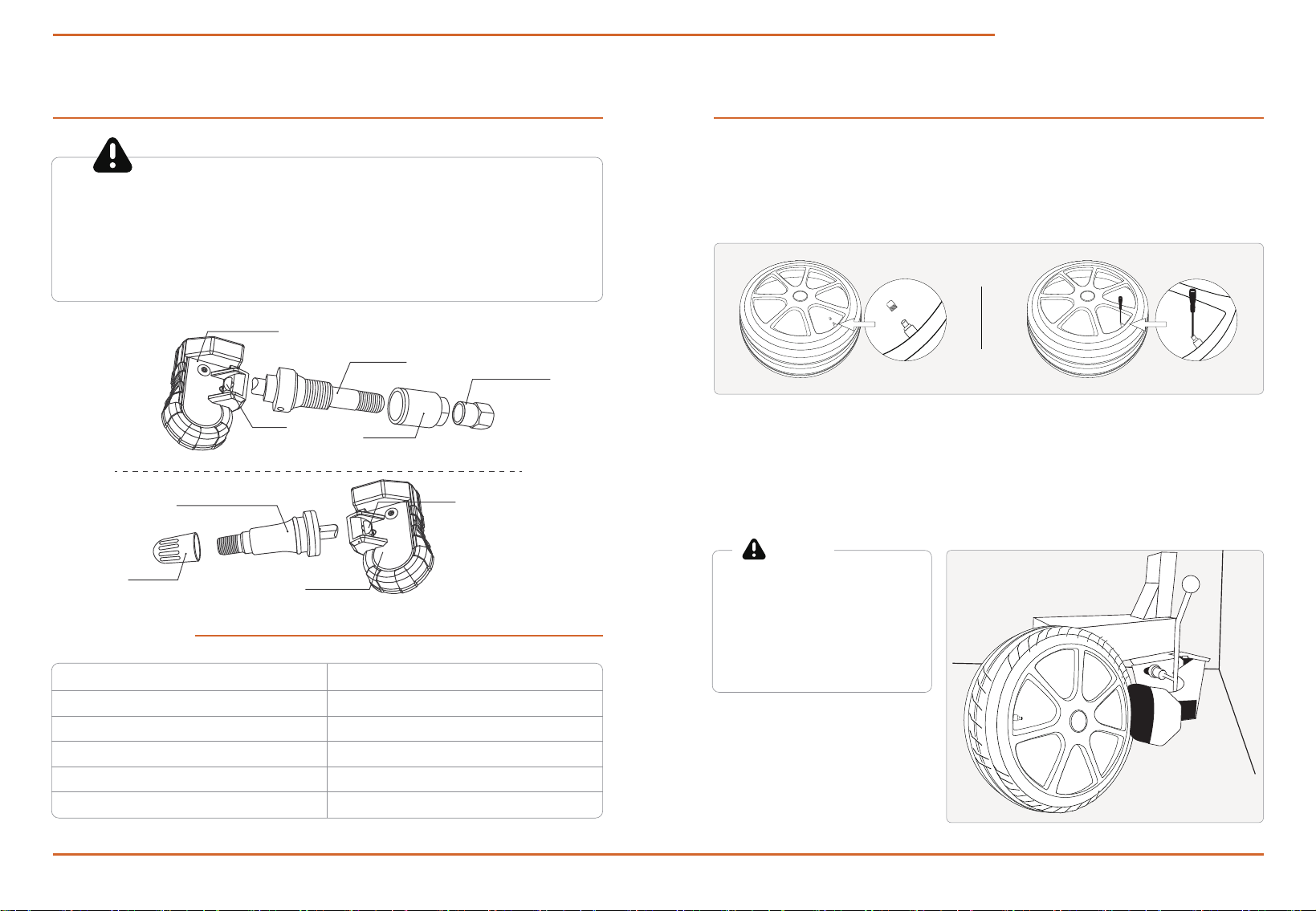
1. Deflating the tire
Place the tire in the tire machine with the TPMS sensor located 180° away from the bead breaker tool arm. Break the
tire bead and remove the tire from the tire machine. Then use a suitable tool to dismantle the TMPS sensor. (Note* in
some cases the tire may have to be removed entirely from the wheel)
2. Dismantling the sensor
Do not directly break the tire bead in
the region of the TPMS sensor as it is
easily damaged. If the TPMS sensor
is a rubber valve snap-in type, please
use the tire valve stem puller tool to
remove.
Caution
Valve Stem
Sensor BodyMetal Valve
Sensor
Rubber Black
Valve Sensor
Nut and washer
Valve Cap
Sensor Body
Rubber Valve Stem
Valve Cap
Screw
Screw
Pictures illustrated here are for reference only and this Quick Start Guide is subject to change without prior notice.
TPMS Sensor Quick Start Guide
When the tire is repaired or disassembled, or if the sensor is disassembled or replaced, the rubber
grommet, grommet, screw nut and valve core must be replaced with original parts to ensure proper
connection. If the sensor is damaged externally, it must be replaced.
Caution
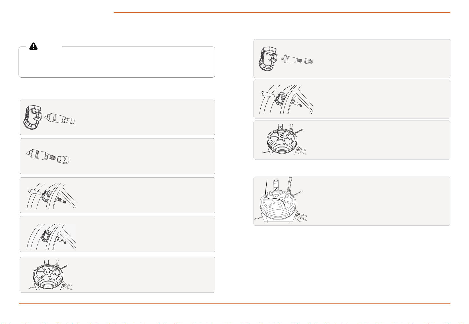
3. Installing sensor
4. Inflating the tire
Rubber Valve Stem Sensor Installation
(1) Connect the sensor body and the valve stem.
(Screw on the back screw but do not tighten it for adjusting the
angle.)
(3) Use the tire valve stem puller to pull the sensor to the proper
position.
(5) Use the tire valve stem puller to pull the sensor to the proper
position.
(2) Install the valve stem on the valve hole of the rim and adjust
the angel between sensor body and the valve stem to fit hub.Then
tighten the back screw.
Metal Valve Stem Sensor Installation
(1) Connect the sensor body and the valve stem.
(Screw on the back screw but do not tighten it for adjusting
the angle.)
(2) Remove the cap, screw nut, and grommet from the stem one by
one.
(4) Install the grommet, screw nut and cap on the stem.
(3) Install the valve stem on the valve hole of the rim and adjust
the angel between sensor body and the valve stem to fit hub.Then
tighten the back screw.
Dismantle the valve core with valve core removal tool. Then inflate
the tire to the nominal value according to the tire data plate the
vehicle. Install the valve core and screw the valve cap.

FCC Warnning:
This equipment has been tested and found to comply with the limits for a Class B digital device,
pursuant to part 15 of the FCC Rules. These limits are designed to provide
reasonable
protection againstharmful interference in a residential installation. This equipment generates,
uses and can radiateradio
frequency
energy
and,
if
not
installed
and
used
in
accordance
with
the
instructions,
maycause
harmful
interference
to
radio
communications.
However,
there
is
no
guarantee
thatinterference
will
not
occur
in
a
particular
installation.
If
this
equipment
does
cause
harmfulinterference to radio or television reception, which can be
determined by turning the equipmentoff
and
on,
the
user
is
encouraged
to
try
to
correct
the
interference
by
one
or
more
of
thefollowing measures:
•
Reorient or relocate the receiving antenna.
•
Increase the separation between the equipment and receiver.
•
Connect the equipment into an outlet on a circuit different from that to which the receiver is
connected.
• Consult the dealer or an experienced radio/TV technician for help.
Caution:
Any
changes
or
modifications
to
this
device
not
explicitly
approved
by
manufacturer
could void your authority to operate this equipment.
This
device
complies
with
part
15
of
the
FCC
Rules.
Operation
is
subject
to
the
following
two
conditions:
(1)This
device
may
not
cause
harmful
interference,
and
(2)
this
device
must
accept
any
interference received, including interference that may cause undesired operation.
This
equipment
complies
with
FCC
radiation
exposure
limits
set
forth
for
an
uncontrolled
environment.
This
equipment
should
be
installed
and
operated
with
minimum
distance
20cm
between the radiator and your body.

