
1
HD500 User's Manual V1.3
Trademarks
FOXWELL is trademark of Shenzhen Foxwell Technology Co., Ltd.
All other marks are trademarks or registered trademarks of their respective holders.
Copyright Information
©2024 Shenzhen Foxwell Technology Co., Ltd.
All rights reserved.
Disclaimer
The information, specifications and illustrations in this manual are based on the latest
information available at the time of printing.
Foxwell reserves the right to make changes at any time without notice.
Visit our website at
www.foxwelltech.us
For Technical Assistance, send us email at
support@foxwelltech.com

2
HD500 User's Manual V1.3
One-Year Limited Warranty
Subject to the conditions of this limited warranty, Shenzhen Foxwell Technology
Co., Ltd (“FOXWELL”) warrants its customer that this product is free of defects in
material and workmanship at the time of its original purchase for a subsequent
period of one (1) year.
In the event this product fails to operate under normal use, during the warranty
period, due to defects in materials and workmanship, FOXWELL will, at its sole
option, either repair or replace the product in accordance with the terms and
conditions stipulated herein.
Terms and Conditions
1 If FOXWELL repairs or replaces the product, the repaired or replaced product
shall be warranted for the remaining time of the original warranty period. No
charge will be made to the customer for replacement parts or labor charges
incurred by FOXWELL in repairing or replacing the defective parts.
2 The customer shall have no coverage or benefits under this limited warranty if
any of the following conditions are applicable:
a) The product has been subjected to abnormal use, abnormal conditions,
improper storage, exposure to moisture or dampness, unauthorized modifications,
unauthorized repair, misuse, neglect abuse, accident, alteration, improper
installation, or other acts which are not the fault of FOXWELL, including damage
caused by shipping.
b) The Product has been damaged from external causes such as collision with an
object, or from fire, flooding, sand, dirt, windstorm, lightning, earthquake or
damage from exposure to weather conditions, an Act of God, or battery leakage,
theft, blown fuse, improper use of any electrical source, or the product was used in
combination or connection with other product, attachments, supplies or
consumables not manufactured or distributed by FOXWELL.
3 The customer shall bear the cost of shipping the product to FOXWELL. And
FOXWELL shall bear the cost of shipping the product back to the customer after the
completion of service under this limited warranty.
4 FOXWELL does not warrant uninterrupted or error-free operation of the product.
If a problem develops during the limited warranty period, the consumer shall take
the following step-by-step procedure:
a) The customer shall return the product to the place of purchase for repair or
replacement processing, contact your local FOXWELL distributor or visit our
website www.foxwelltech.us to get further information.

3
HD500 User's Manual V1.3
b) The customer shall include a return address, daytime phone number and/or fax
number, complete description of the problem and original invoice specifying date
of purchase and serial number.
c) The customer will be billed for any parts or labor charges not covered by this
limited warranty.
d) FOXWELL will repair the Product under the limited warranty within 30 days after
receipt of the product. If FOXWELL cannot perform repairs covered under this
limited warranty within 30 days, or after a reasonable number of attempts to
repair the same defect, FOXWELL at its option, will provide a replacement product
or refund the purchase price of the product less a reasonable amount for usage.
e) If the product is returned during the limited warranty period, but the problem
with the product is not covered under the terms and conditions of this limited
warranty, the customer will be notified and given an estimate of the charges the
customer must pay to have the product repaired, with all shipping charges billed to
the customer. If the estimate is refused, the product will be returned freight collect.
If the product is returned after the expiration of the limited warranty period,
FOXWELL’ normal service policies shall apply and the customer will be responsible
for all shipping charges.
5 ANY IMPLIED WARRANTY OF MERCHANTABILITY, OR FITNESS FOR A PARTICULAR PURPOSE
OR USE, SHALL BE LIMITED TO THE DURATION OF THE FOREGOING LIMITED WRITTEN
WARRANTY. OTHERWISE, THE FOREGOING LIMITED WARRANTY IS THE CONSUMER’S SOLE
AND EXCLUSIVE REMEDY AND IS IN LIEU OF ALL OTHER WARRANTIES, EXPRESS OR IMPLIED.
FOXWELL SHALL NOT BE LIABLE FOR SPECIAL, INCIDENTAL, PUNITIVE OR CONSEQUENTIAL
DAMAGES, INCLUDING BUT NOT LIMITED TO LOSS OF ANTICIPATED BENEFITS OR PROFITS,
LOSS OF SAVINGS OR REVENUE, LOSS OF DATA, PUNITIVE DAMAGES, LOSS OF USE OF THE
PRODUCT OR ANY ASSOCIATED EQUIPMENT, COST OF CAPITAL, COST OF ANY SUBSTITUTE
EQUIPMENT OR FACILITIES, DOWNTIME, THE CLAIMS OF ANY THIRD PARTIES, INCLUDING
CUSTOMERS, AND INJURY TO PROPERTY, RESULTING FROM THE PURC HASE OR USE OF THE
PRODUCT OR ARISING FROM BREACH OF THE WARRANTY, BREACH OF CONTRACT,
NEGLIGENCE, STRICT TORT, OR ANY OTHER LEGAL OR EQUITABLE THEORY, EVEN IF FOXWELL
KNEW OF THE LIKELIHOOD OF SUCH DAMAGES. FOXWELL SHALL NOT BE LIABLE FOR DELAY
IN RENDERING SERVICE UNDER THE LIMITED WARRANTY, OR LOSS OF USE DURING THE
PERIOD THAT THE PRODUCT IS BEING REPAIRED.
6 Some states do not allow limitation of how long an implied warranty lasts, so the
one-year warranty limitation may not apply to you (the Consumer). Some states do
not allow the exclusion or limitation of incidental and consequential damages, so
certain of the above limitations or exclusions may not apply to you (the Consumer).
This limited warranty gives the Consumer specific legal rights and the Consumer
may also have other rights which vary from state to state.

4
HD500 User's Manual V1.3
Safety Information
For your own safety and the safety of others, and to prevent damage to the
equipment and vehicles, read this manual thoroughly before operating your tool.
The safety messages presented below and throughout this user’s manual are
reminders to the operator to exercise extreme care when using this device. Always
refer to and follow safety messages and test procedures provided by vehicle
manufacturer. Read, understand and follow all safety messages and instructions in
this manual.
Safety Message Conventions Used
We provide safety messages to help prevent personal injury and equipment
damage. Below are signal words we used to indicate the hazard level in a condition.
Indicates an imminently hazardous situation which, if not avoided, will result in
death or serious injury to the operator or to bystanders.
Indicates a potentially hazardous situation which, if not avoided, could result in
death or serious injury to the operator or to bystanders.
Indicates a potentially hazardous situation which, if not avoided, may result in
moderate or minor injury to the operator or to bystanders.
Important Safety Instructions
And always use your tool as described in the user’s manual, and follow all safety
messages.
● Do not route the test cable in a manner that would interfere with driving
controls.
● Do not exceed voltage limits between inputs specified in this user’s manual.
● Always wear ANSI approved goggles to protect your eyes from propelled objects
as well as hot or caustic liquids.
● Fuel, oil vapors, hot steam, hot toxic exhaust gases, acid, refrigerant and other
debris produced by a malfunction engine can cause serious injury or death. Do

5
HD500 User's Manual V1.3
not use the tool in areas where explosive vapor may collect, such as in
below-ground pits, confined areas, or areas that are less than 18 inches (45 cm)
above the floor.
● Do not smoke, strike a match, or cause a spark near the vehicle while testing and
keep all sparks, heated items and open flames away from the battery and fuel /
fuel vapors as they are highly flammable.
● Keep a dry chemical fire extinguisher suitable for gasoline, chemical and electrical
fires in work area.
● Always be aware of rotating parts that move at high speed when an engine is
running and keep a safe distance from these parts as well as other potentially
moving objects to avoid serious injury.
● Do not touch engine components that get very hot when an engine is running to
avoid severe burns.
● Block drive wheels before testing with engine running. Put the transmission in
park (for automatic transmission) or neutral (for manual transmission). And
never leave a running engine unattended.
● Do not wear jewelry or loose fitting clothing when working on engine.
● Don't connect or disconnect the equipments while the ignition is on or the
engine is running.

6
HD500 User's Manual V1.3
Table of Contents
ONE-YEAR LIMITED WARRANTY .............................................................................................................. 2
SAFETY INFORMATION ........................................................................................................................... 4
S
AFETY
M
ESSAGE
C
ONVENTIONS
U
SED
...........................................................................................................4
I
MPORTANT
S
AFETY
I
NSTRUCTIONS
................................................................................................................4
1 USING THIS MANUAL ........................................................................................................................... 9
1.1 B
OLD
T
EXT
....................................................................................................................................... 9
1.2 S
YMBOLS AND
I
CONS
........................................................................................................................... 9
1.2.1 Solid Spot ............................................................................................................................... 9
1.2.2 Arrow Icon ............................................................................................................................. 9
1.2.3 Note and Important Message ................................................................................................... 9
2 INTRODUCTION ................................................................................................................................. 10
2.1 S
CANNER
D
ESCRIPTIONS
..................................................................................................................... 10
2.2 A
CCESSORIES
...................................................................................................................................11
2.3 T
ECHNICAL
S
PECIFICATIONS
................................................................................................................. 12
3 GETTING STARTED ............................................................................................................................. 13
3.1 P
OWERING UP THE
S
CANNER
............................................................................................................... 13
3.1.1 Internal Battery Pack............................................................................................................. 13
3.1.2 External Power Supply ........................................................................................................... 14
3.2 S
HUTTING
D
OWN THE
S
CANNER
........................................................................................................... 14
3.3 S
CREEN
L
AYOUT OF
H
OME
S
CREEN
........................................................................................................ 14
3.3.1 Application Menu ..................................................................................................................15
3.3.2 Diagnostic Menu ................................................................................................................... 15
4 MY ACCOUNT .................................................................................................................................... 17
4.1 R
EGISTRATION
................................................................................................................................. 18
4.2 S
IGN IN
......................................................................................................................................... 20
4.2.1 Product activate ....................................................................................................................20
4.3 M
Y
A
CCOUNT
................................................................................................................................. 22
4.4 M
Y
P
RODUCTS
................................................................................................................................ 22
4.5 F
EEDBACK AND
S
UGGESTIONS
...............................................................................................................22
5 UPDATE............................................................................................................................................ 24
5.1 A
UTOMATIC
U
PDATE
......................................................................................................................... 24
5.2 M
ANUAL
U
PDATE
.............................................................................................................................24
6 VCI MANAGER ................................................................................................................................... 25
7 FIRMWARE UPDATE ...........................................................................................................................27

7
HD500 User's Manual V1.3
8 VEHICLE IDENTIFICATION ................................................................................................................... 28
8.1 VEHICLE CONNECTION ........................................................................................................................29
8.2 VEHICLE HISTORY ............................................................................................................................. 30
9 DIAGNOSIS ........................................................................................................................................31
9.1 VEHICLE IDENTIFICATION ..................................................................................................................... 32
9.1.1 Quick Scan ............................................................................................................................33
9.1.2 Control Modules ................................................................................................................... 34
9.2 DIAGNOSTIC OPERATIONS ................................................................................................................... 35
9.2.1 ECU Information ................................................................................................................... 36
9.2.2 Read Codes .......................................................................................................................... 37
9.2.3 Clear Codes .......................................................................................................................... 38
9.2.4 Live Data .............................................................................................................................. 38
9.2.4.1 All Data ..................................................................................................................... 39
9.2.4.2 Custom List ............................................................................................................... 43
9.2.4.3 Record data .............................................................................................................. 43
9.2.5 Active Test ............................................................................................................................44
9.3 SERVICE ......................................................................................................................................... 47
10 OBD ................................................................................................................................................ 48
10.1 QUICK SCAN ................................................................................................................................. 48
10.2 DIAGNOSTIC OPERATIONS ................................................................................................................. 50
10.2.1 ECU Information ..................................................................................................................50
10.2.2 Read Codes .........................................................................................................................51
10.2.3 Clear Codes .........................................................................................................................51
11 ABS .................................................................................................................................................52
11.1 VEHICLE IDENTIFICATION ................................................................................................................... 53
11.2 DIAGNOSTIC OPERATIONS ................................................................................................................. 54
11.2.1 ECU Information ..................................................................................................................54
11.2.2 Read Codes .........................................................................................................................55
11.2.3 Clear Codes .........................................................................................................................56
11.2.4 Live Data ............................................................................................................................ 56
12 LIMIT .............................................................................................................................................. 57
13 DPF .................................................................................................................................................59
14 INJECTOR CUTOFF ............................................................................................................................ 62
15 AUXILIARY TOOLS ............................................................................................................................ 65
15.1 FILE BROWSER ............................................................................................................................... 65
15.2 PIN DETECTION .............................................................................................................................. 65
16 DATA MANAGER ..............................................................................................................................66

8
HD500 User's Manual V1.3
16.1 IMAGE .........................................................................................................................................67
16.1.1 How to Save an Image ......................................................................................................... 67
16.1.2 Review Image ..................................................................................................................... 68
16.2 PDF REPORT .................................................................................................................................69
16.2.1 How to Create a PDF Report ................................................................................................. 69
16.2.2 Review PDF Report .............................................................................................................. 71
16.3 DATA PLAYBACK ............................................................................................................................. 71
17 SETTINGS ........................................................................................................................................ 73
17.1 UNIT ...........................................................................................................................................73
17.2 LANGUAGE ................................................................................................................................... 74
17.3 FONT SIZE .................................................................................................................................... 74
17.4 MODULE SORTING .......................................................................................................................... 74
17.5 SORT TILES ................................................................................................................................... 75
17.6 REMOTE CONTROL .......................................................................................................................... 75
17.7 AUTOMATIC UPDATE ....................................................................................................................... 76
17.8 SYSTEM SETTINGS ........................................................................................................................... 76
17.9 GENERAL ......................................................................................................................................76
17.10 UNINSTALL VEHICLE SOFTWARE .........................................................................................................76
17.11 CLEAR APP DATA .......................................................................................................................... 77
17.12 PRINT SETTINGS ........................................................................................................................... 78
17.13 ABOUT ...................................................................................................................................... 79
18 SHOP MANAGER..............................................................................................................................80
18.1 VEHICLE HISTORY ............................................................................................................................81
18.2 WORKSHOP .................................................................................................................................. 81
18.3 CUSTOMER ................................................................................................................................... 82
19 REMOTE SUPPORT ........................................................................................................................... 82

9
HD500 User's Manual V1.3
1 Using This Manual
We provide tool usage instructions in this manual. Below are the conventions we
used in the manual.
1.1 Bold Text
Bold text is used to highlight selectable items such as buttons and menu options.
Example:
Select Diagnostic from the Home screen of the HD500 application.
1.2 Symbols and Icons
1.2.1 Solid Spot
Operation tips and lists that apply to specific tool are introduced by a solid spot.
Example:
Data Manager menu let you review stored screenshots and test reports, playback
recorded live data and other saved files.
Typical menu options include:
● Image
● PDF
● Data Playback
● Data Record
● Report
1.2.2 Arrow Icon
An arrow icon indicates a procedure.
Example:
To connect to wall plug:
1. Connect the USB Type-C charge cable to scanner and plug it to the wall socket.
2. Press the power switch of the scan tool to power it on; meanwhile the
scanner tool starts charging automatically also.
1.2.3 Note and Important Message
Note
A NOTE provides helpful information such as additional explanations, tips, and
comments.
Example:
10
HD500 User's Manual V1.3
NOTE
Test results do not necessarily indicate a faulty component or system.
Important
IMPORTANT indicates a situation, which if not avoided, may result in damage to
the test equipment or vehicle.
Example:
IMPORTANT
Do not soak scanner as water might find its way into the scanner.
2 Introduction
HD500 is newly developed diagnostic scanner with 5.5 inch TFT touch screen and
Android 9.0 operating system that delivers OE-level diagnosis for different truck
brands and supports the most commonly required service. Through hardware and
software upgrades, technical staff and enthusiasts can now approach problems
with greater speed and accuracy.
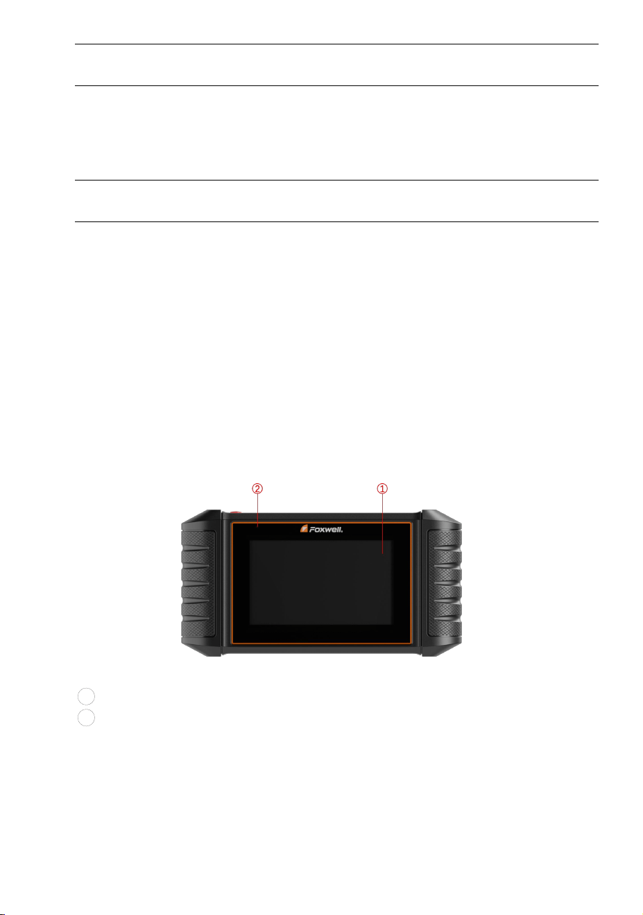
2.1 Scanner Descriptions
This section illustrates external features, ports and connectors of the scanner.
Figure 2-1 Front View
1
5.5” TFT LCD Touch Screen- shows menus, test results and operation tips.
2 Power Status Indicator - indicates the power status of the scanner.

11
HD500 User's Manual V1.3
Figure 2-2 Top View
3 Power Switch - turns on the scanner, goes to sleep mode or wake up the
scanner from sleep mode. Press and hold for 3 seconds for start or emergency
shutdown. Double click to screenshot.
4
USB Type-C Port - connects to wall plug to charge the scanner and can be used
for data transfer.
5 USB Type-A Port - provides a USB connection for the external storage devices.
6 Diagnostic Port -provides connection between vehicle and the scanner.
IMPORTANT
Do not use solvents such as alcohol to clean display. Use a mild nonabrasive
detergent and a soft cotton cloth.
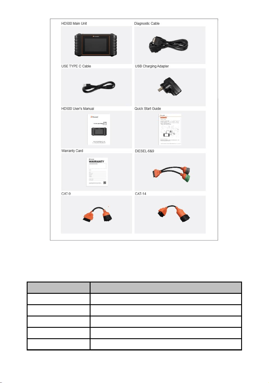
2.2 Accessories
This section lists the accessories that go with the scanner. If you find any of the
following items missing from your package, contact your local dealer for assistance.
12
HD500 User's Manual V1.3
Table 2-3 Accessories
2.3 Technical Specifications
Item
Description
Screen
5.5’’ TFT Capacitive LCD screen; 1280*720 pixel
Operation System
Android 9.0
Processor
MT8167 1.3GHz
Memory
1GB
SSD Hard drive
32GB

13
HD500 User's Manual V1.3
Table 2-4 Technical Specifications
3 Getting Started
This section describes how to power on/down the scanner, provides brief
introductions of applications loaded on the scanner and display screen layout of
the scan tool.
3.1 Powering up the Scanner
Before using the HD500 applications (including updating the scanner), please make
sure to provide power to the scanner.
The unit operates on any of the following sources:
● Internal Battery Pack
● External Power Supply
3.1.1 Internal Battery Pack
The tablet scanner can be powered with the internal rechargeable battery. The
fully charged battery is capable of providing power for 5 hours of continuous
operation.
NOTE
Please turn off the tablet to save power when not use.
Communication interface
Built-in WIFI 802.11 b/g/n Wireless LAN
USB2.0 OTG/standard USB 2.0 HOST
Bluetooth specification v2.1+EDR; Bluetooth 4.0 Low Energy (LE)
(10-20 m)
Built-in Battery
4000mAh, Lithium-polymer battery, chargeable via 5V USB power
supply
Protocols
ISO9141-2, ISO14230-2, ISO15765-4, K/L lines, Double K Line
SAE-J1850 VPW,SAE-J1850PWM,CAN ISO 11898, High-speed,
Middle-speed, Lows-peed and Single wire CAN, KW81, KW82, GM
UART, UART Echo Byte Protocol, Honda Diag-H Protocol, TP2.0,
TP1.6, SAE J1939, SAE J1708,Fault-Tolerant CAN,CAN FD, DOIP,
J1939,J1708,ISO27145
Working Temperature
-10 to 70°C
Storage Temperature
-20 to 80°C
Operating Humidity
5%-95% Non-Condensing
Dimensions
236*124*38mm (L*W*H)
Weight
0.87kg (Main unit)
14
HD500 User's Manual V1.3
3.1.2 External Power Supply
The tablet can also be powered from a wall socket using the USB charging adapter.
The tablet also charges its internal battery pack through USB Type-C cable.
3.2 Shutting Down the Scanner
All vehicle communication must be terminated before shutting down the scanner.
Exit the Diagnostic application before powering down.
To shut down the scanner:
1. Press and hold the Power button of the scanner for 3 seconds.
2. Click the Power off to shut down or Reboot to restart.
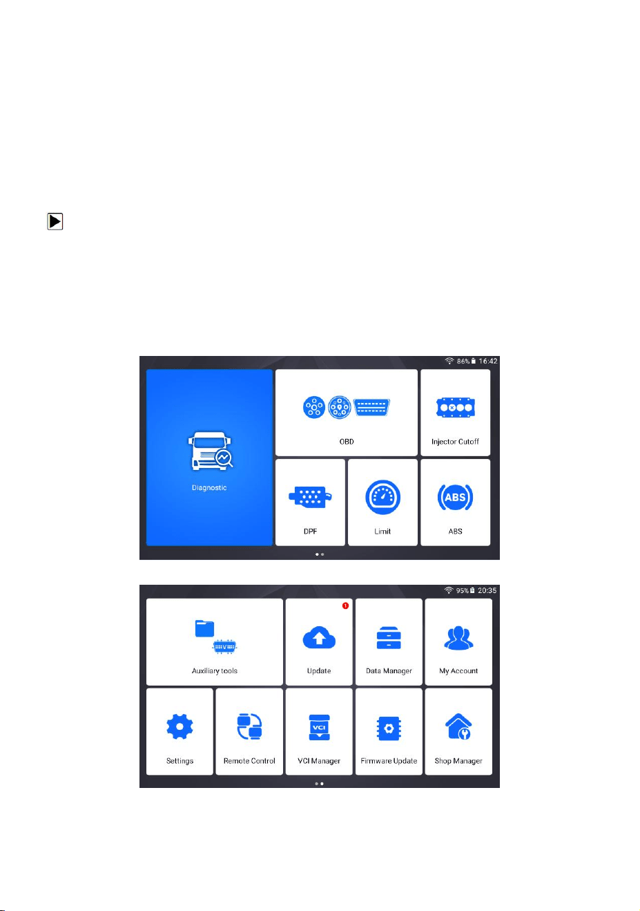
3.3 Screen Layout of Home Screen
After the scanner turning on, the screen show main menu of the application.
Figure 3-1 Sample Home Screen
Figure 3-2 Sample Home Screen

15
HD500 User's Manual V1.3
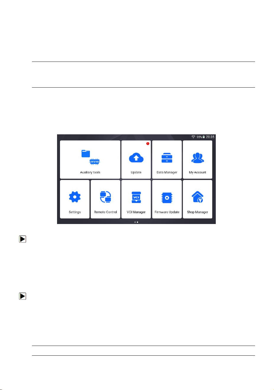
3.3.1 Application Menu
This section briefly introduces the applications that are preloaded into the scanner:
● Diagnostic - leads to test screens for diagnostic trouble code information,
freeze frame, live data and ECU information.
● OBD - OBD refers to the on-board diagnostic system used to monitor and
diagnose the working status and fault information of the vehicle.
● ABS -Give full play to the effectiveness of the brakes and shorten braking time
and distance.
● Limit -Check and set the engine speed and the vehicle road speed limit when
the vehicle is stationary.
● DPF -View diesel emissions levels with brake data.
● Injector cutoff -When idling, manually stop any cylinder and observe whether
the working status of the engine changes to analyze whether the working
performance of the cylinder is normal.
● Auxiliary tools -File storage and pin detection.
● Update - leads to screens for Foxwell ID registration and updating the scanner.
● Data Manager - leads to screens for saved screenshots, pictures and test
reports, and playing back live data, as well as debug logging data.
● My Account - displays your Foxwell ID information like registered products and
personal information and allows for sending us feedback about the scanner.
● Settings - leads to screens for adjusting default settings to meet your own
preference and view information about the scanner.
● Remote Control - leads to TeamViewer to get remote support from Foxwell
team or remote vehicle diagnostic.
● VCI Manager – VCI manage (VCI binding, unbinding, re-scan vehicle software).
● Firmware Update – VCI firmware update.
● Shop manager –Allow technicians to manage shop information and vehicle test
records.
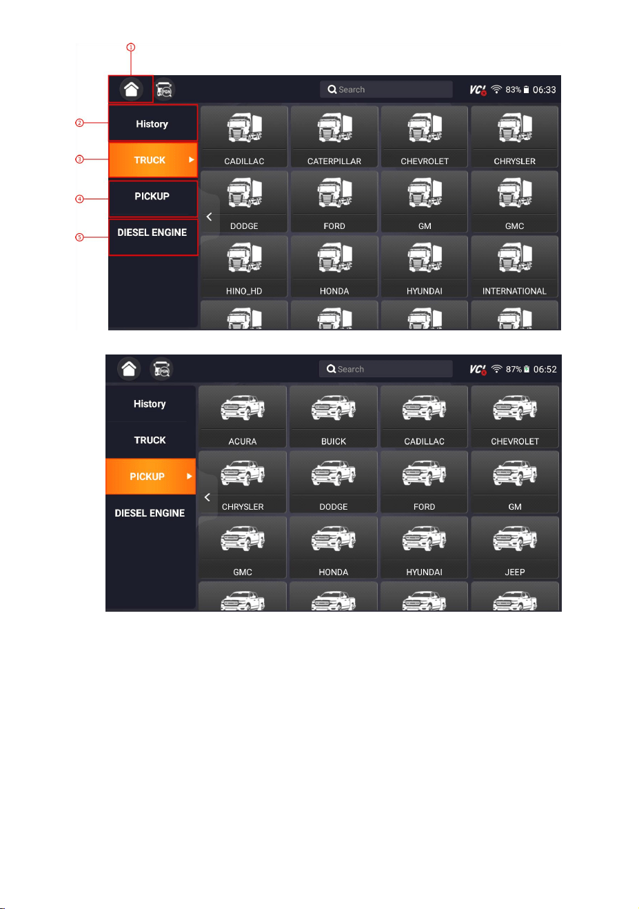
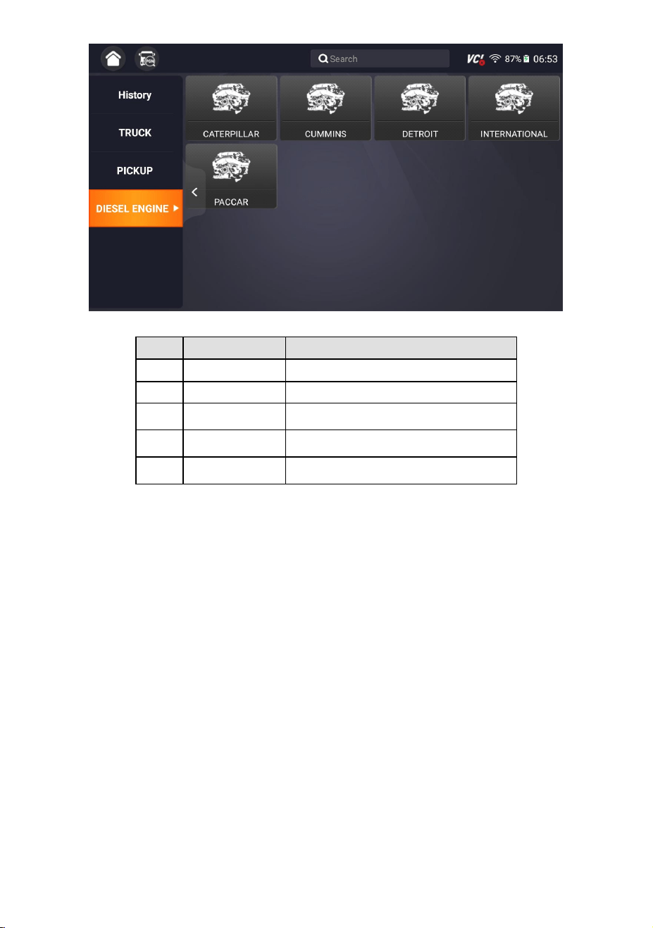
3.3.2 Diagnostic Menu
Touch Diagnostic at the HD500 application menu, and the Diagnostic menu will
display. The operations of the buttons of Diagnostic menu are described in the
below table.
16
HD500 User's Manual V1.3
Figure 3-3 Sample Diagnostic Menu Screen
Figure 3-4 Sample Diagnostic Menu Screen
17
HD500 User's Manual V1.3
Figure 3-5 Sample Diagnostic Menu Screen
No.
Name
Description
1
Home
Back to the Application Menu.
2
History
Displays the tested vehicle records.
3
TRUCK
Displays the detectable brand of the truck.
4
PICKUP
Displays the detectable brand of the pickup.
5
DIESEL ENGINE
Display available diesel engine brands.
Table 3-6 Title Bar of Diagnostic Menus
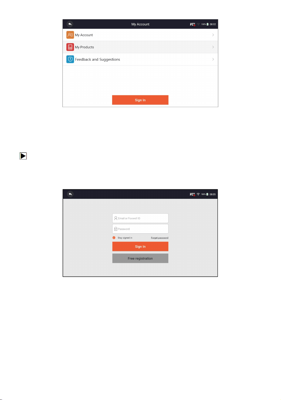
4 My Account
This section introduces user account registration, login, device activation and other
information.
When My Account application is selected, a menu with available options displays.
My Account Menu options typically include:
● My Account
● My Products
● Feedback and Suggestions
18
HD500 User's Manual V1.3
Figure 4-1 Sample My Account Interface
4.1 Registration
You are allowed to create a Foxwell ID with the built-in client.
To register with built-in client:
1. Press My Account or Update from home screen of HD500 diagnostic application,
the user login page will show, then press Free registration button to register an
account.
Figure 4-2 Sample Update Client Interface
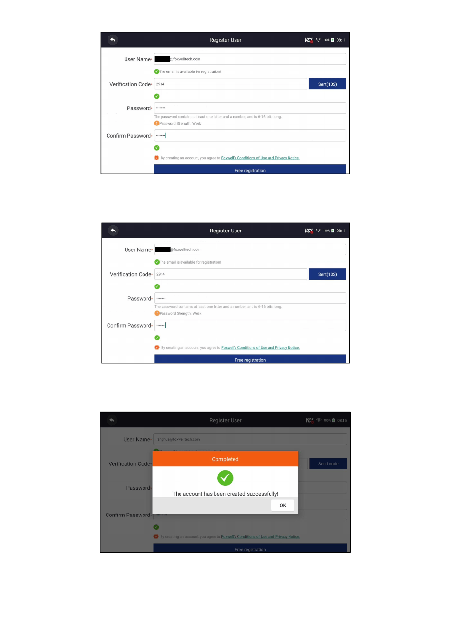
2. Enter the User Name (use one of your existing mail addresses as user name),
and press Send Code button for get a verification code, Foxwell will send a
4-digit verification code to the email you just entered.
19
HD500 User's Manual V1.3
Figure 4-3 Sample ID Registration Screen
3. Get the security code in your mailbox, input the code as verification code. Then
create a password and click Free Registration to complete.
Figure 4-4 Sample ID Registration Screen
4. “The account has been created successfully” message will appear if you
registered successfully.
Figure 4-5 Sample Registration Done Screen
20
HD500 User's Manual V1.3
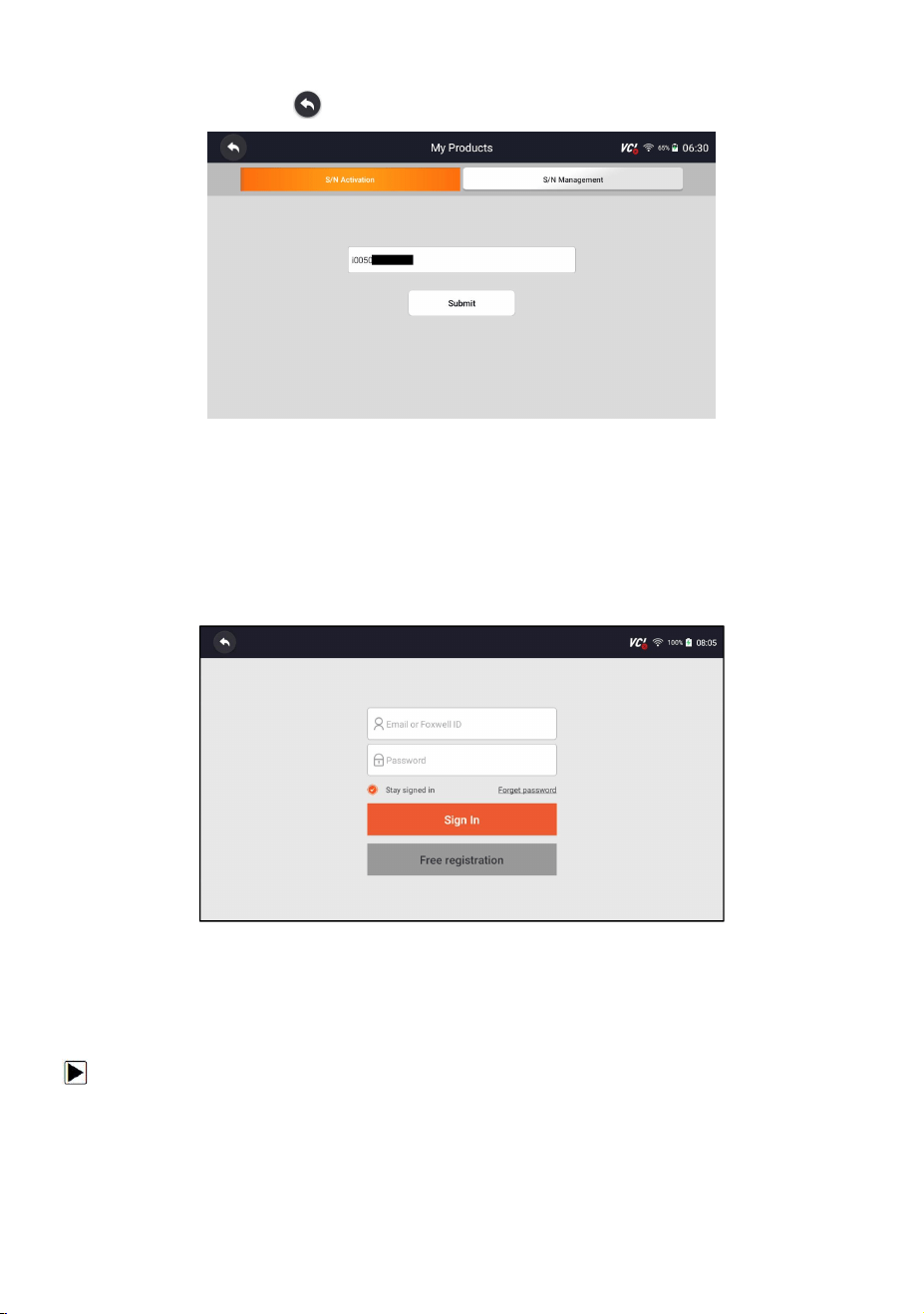
5. The serial number will show after registration. Click Submit to activate the
product or press to back.
Figure 4-6 Sample Product Activation Screen
4.2 Sign in
Press My Account or Update from home screen of HD500 diagnostic application,
the user login page will show, enter your FOXWELL ID and password, and press Sign
in button to sign in.
Figure 4-7 Sample Log in Screen
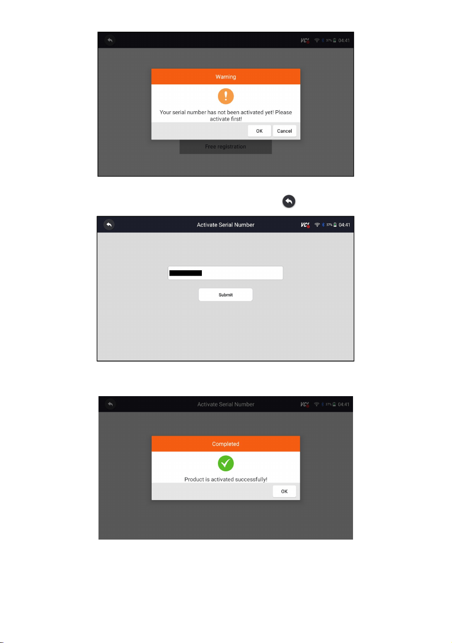
4.2.1 Product activate
If you are logging in for the first time, it will prompt and guide you to activate the
current device while sign in successfully.
To activate product
1. Press OK button to activate product and press Cancel to back.
21
HD500 User's Manual V1.3
Figure 4-8 Sample Product Activation Screen
2.Click Submit to continue the activation and press to give up activation.
Figure 4-9 Sample Product Activation Submit Screen
3. “Product is activated successfully” message will appear if activate successfully.
Figure 4-10 Sample Activate Success Screen
22
HD500 User's Manual V1.3
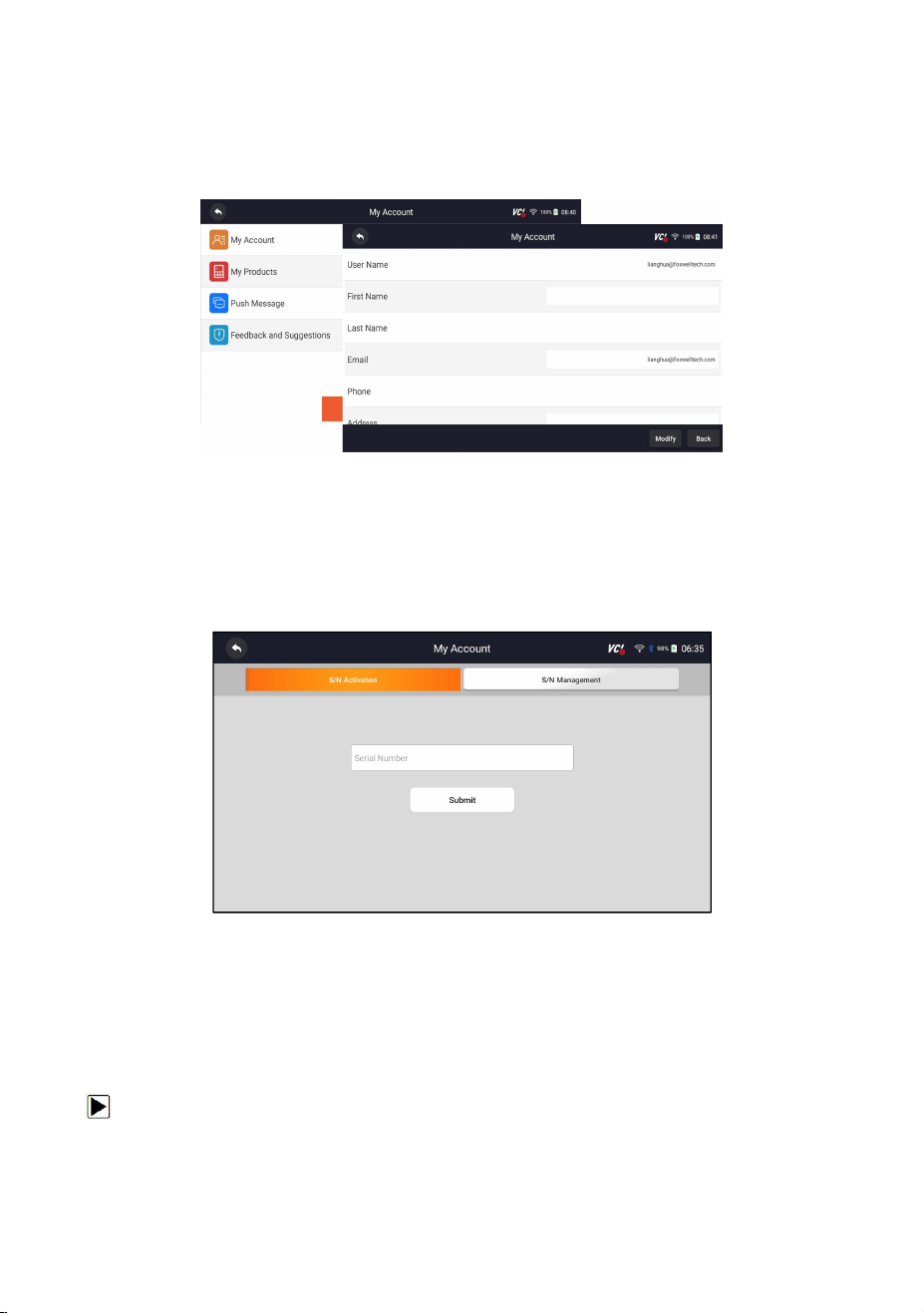
4.3 My Account
My Account option allows you to check and modify or complete your account
information including user name, e-mail, telephone, address and so on.
Figure 4-11 Sample My Account Screen
4.4 My Products
This option let you activate a new product and manage activated products
including serial number and expiration date.
Figure 4-12 Sample My Product Screen
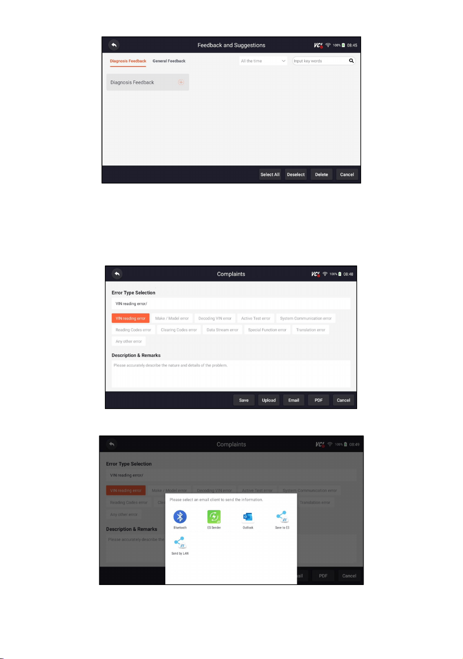
4.5 Feedback and Suggestions
This option allows you to log on your e-mail and send feedback and suggestions
about Foxwell products.
To send feedback and suggestions about Foxwell products:
1. Press My Account from home screen of the HD500 diagnostic application.
2. Press Feedback and Suggestions option to show Feedback page, there are
two options--Diagnosis Feedback and General Feedback.
23
HD500 User's Manual V1.3
Figure 4-13 Sample Feedback Record Screen
3. Select Diagnosis Feedback or General Feedback for creating a feedback.
Select the type of error and some necessary content and problem description or
attachments. Press Save button to save the feedback. Or press Email button to
send if you have an email account.
Figure 4-14 Sample Feedback Edit Screen
Figure 4-15 Sample Email Select Screen
24
HD500 User's Manual V1.3
5 Update
The scanner can be updated to keep you stay current with the latest development
of diagnosis. This section illustrates how to register and update your scan tool. You
can register both on Foxwell website or by the built-in update client.
NOTE
Before registration and updating, please make sure your network works correctly
and the tablet is fully charged or connect to external power supply.
5.1 Automatic Update
When the automatic update is enabled, an update symbol is displayed in the upper
right corner if any software version is released.
Figure 5-1 Sample Automatic Update Screen
To automatic update:
1. Press Settings from home screen of the HD500 diagnostic application.
2. Select Automatic Update, then set automatic update notice enable.
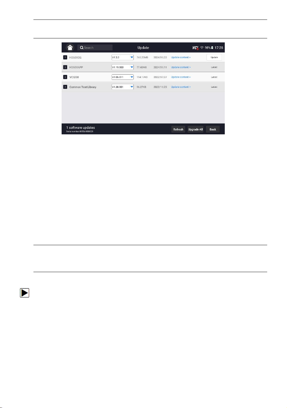
5.2 Manual Update
To update the diagnostic application:
1. Press Update of HD500 diagnostic application, and the update client starts up
automatically.
2. The available updates display. Click the check box(s) in front of the software you
wish to update and then click the Update button to download.
3. When all the items are updated, an “Update Done” message displays.
NOTE
25
HD500 User's Manual V1.3
Please make sure your network works correctly and the tablet is fully charged or
connect to external power supply.
Figure 5-2 Sample Update Screen
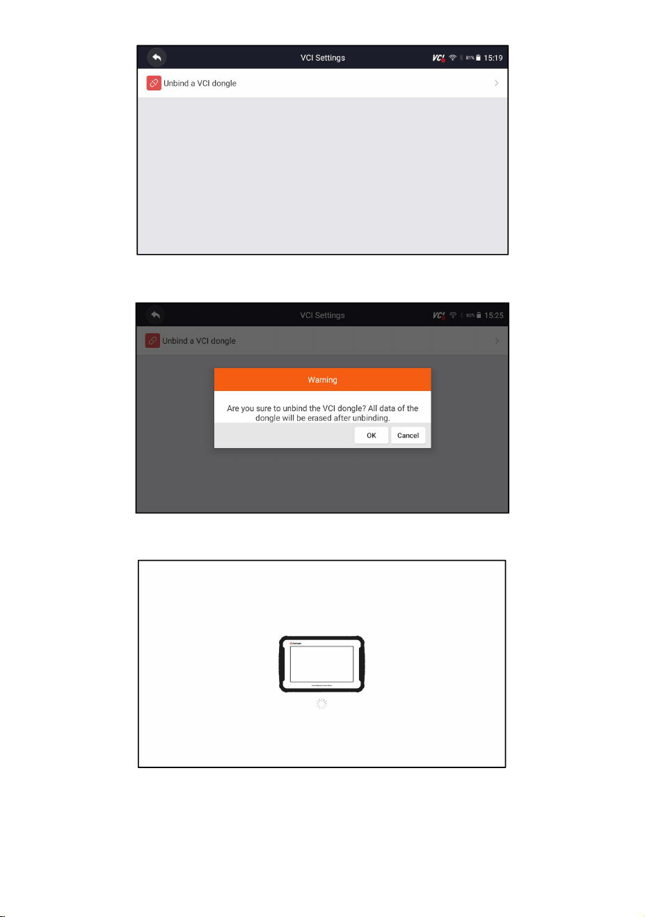
6 VCI Manager
VCI Manager is used to unbind and bind the built-in VCI. When the built-in VCI
needs to be replaced, you need to use this function to unbind the old VCI and
re-bind the replaced built-in VCI.
Even if the VCI is not replaced, the existing VCI device will be automatically
unbound when unbinding, and then the existing VCI will be automatically bound,
and the software of all vehicles in the device will be rescanned and refreshed, and
finally the APP will be restarted.
NOTE
This function cannot be bound to an external VCI, but can only be bound to a
built-in VCI.
VCI unbind & rebind
:
1. Click VCI Manager application on the HD500 home screen.
2. After clicking Unbind a VCI dongle, it will display whether to unbind the current
VCI. When clicking OK, it will execute unbind, rebind, and refresh the vehicle.
26
HD500 User's Manual V1.3
Figure 6-1 Sample Unbind a VCI dongle
Figure 6-2 Sample Unbinding Confirmation Prompt
Figure 6-3 Sample Unbinding Current VCI
27
HD500 User's Manual V1.3
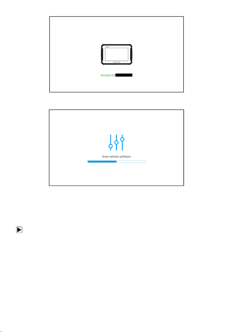
Figure 6-4 Sample Bind New VCI Successfully
Figure 6-5 Sample Rescan Vehicle Software
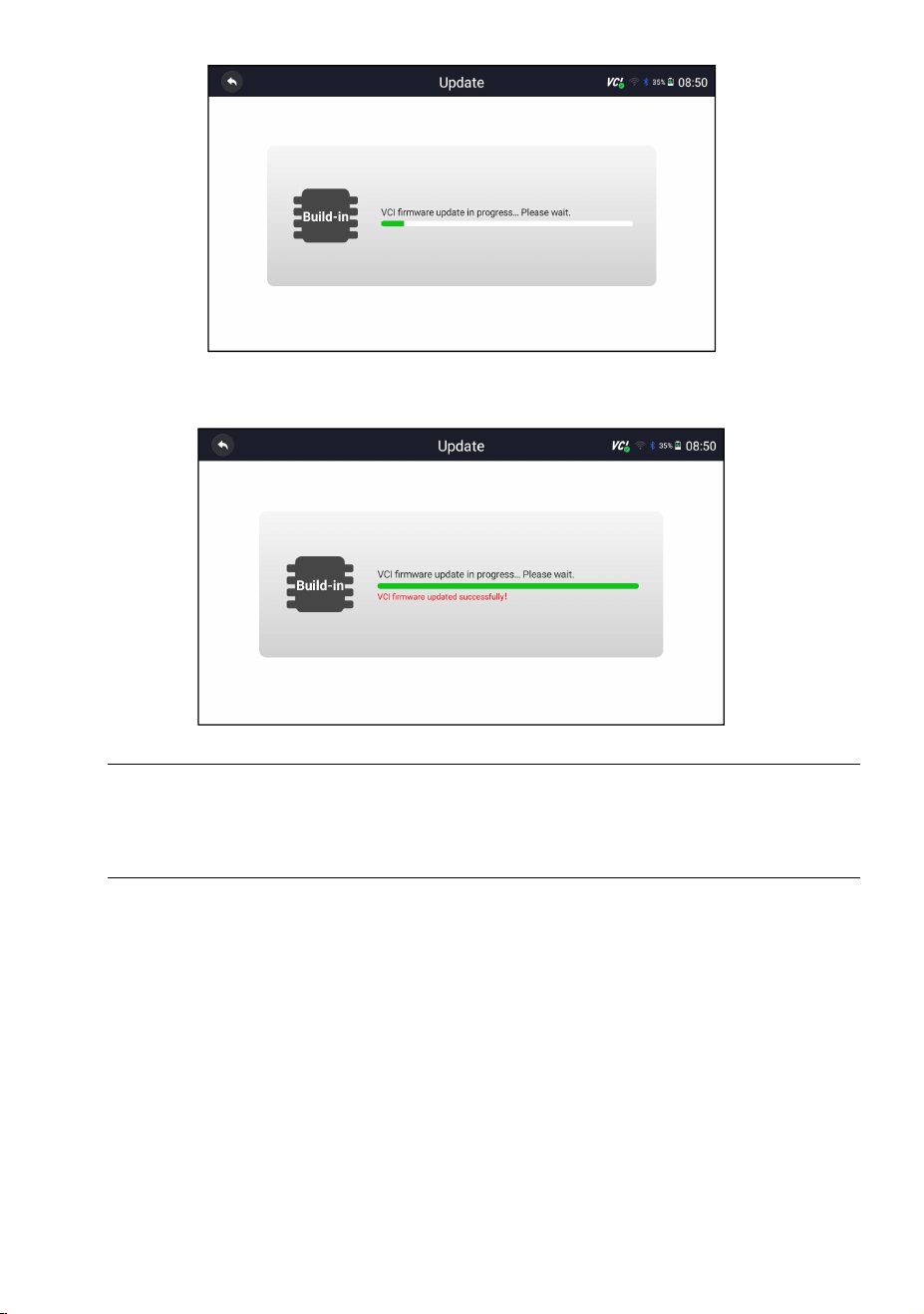
7 Firmware Update
This application allows you to update the firmware of HD500.
To update the firmware:
1. Click the Update application on the HD500 home screen.
2. Check and download the firmware package.
3. After the download is completed, it will automatically jump to the Firmware
Update function module.
4. Check the battery level to ensure that the battery level should be greater
than 20%.
5. It will start update automatically if there is an update available. If update failed,
please follow the on-screen instructions to troubleshoot and repeat the update.
28
HD500 User's Manual V1.3
Figure 7-1 Sample Firmware Update Screen
6. “VCI firmware successfully message” will appear if update successfully.
Figure 7-2 Sample Firmware Update Successfully Screen
NOTE
If there is a firmware update available, the update file will be downloaded and
saved automatically when you try to update the diagnostic software. And you will
be prompted to upgrade the firmware.
8 Vehicle Identification
This section illustrates how to use the scanner to identify the specifications of the
vehicle under test.
The vehicle identification information presented is provided by the ECM of the
vehicle being tested. Therefore, certain attributes of the test vehicle must be
entered into the scan tool to ensure the data displays correctly. The vehicle
identification sequence is menu driven. Simply follow the screen prompts and
make a series of choices. Each selection you make advances you to the next screen.
Exact procedures may vary somewhat by vehicle.
29
HD500 User's Manual V1.3
NOTE
Not all identification options listed above are applicable to all vehicles. Available
options may vary by vehicle manufacturer.
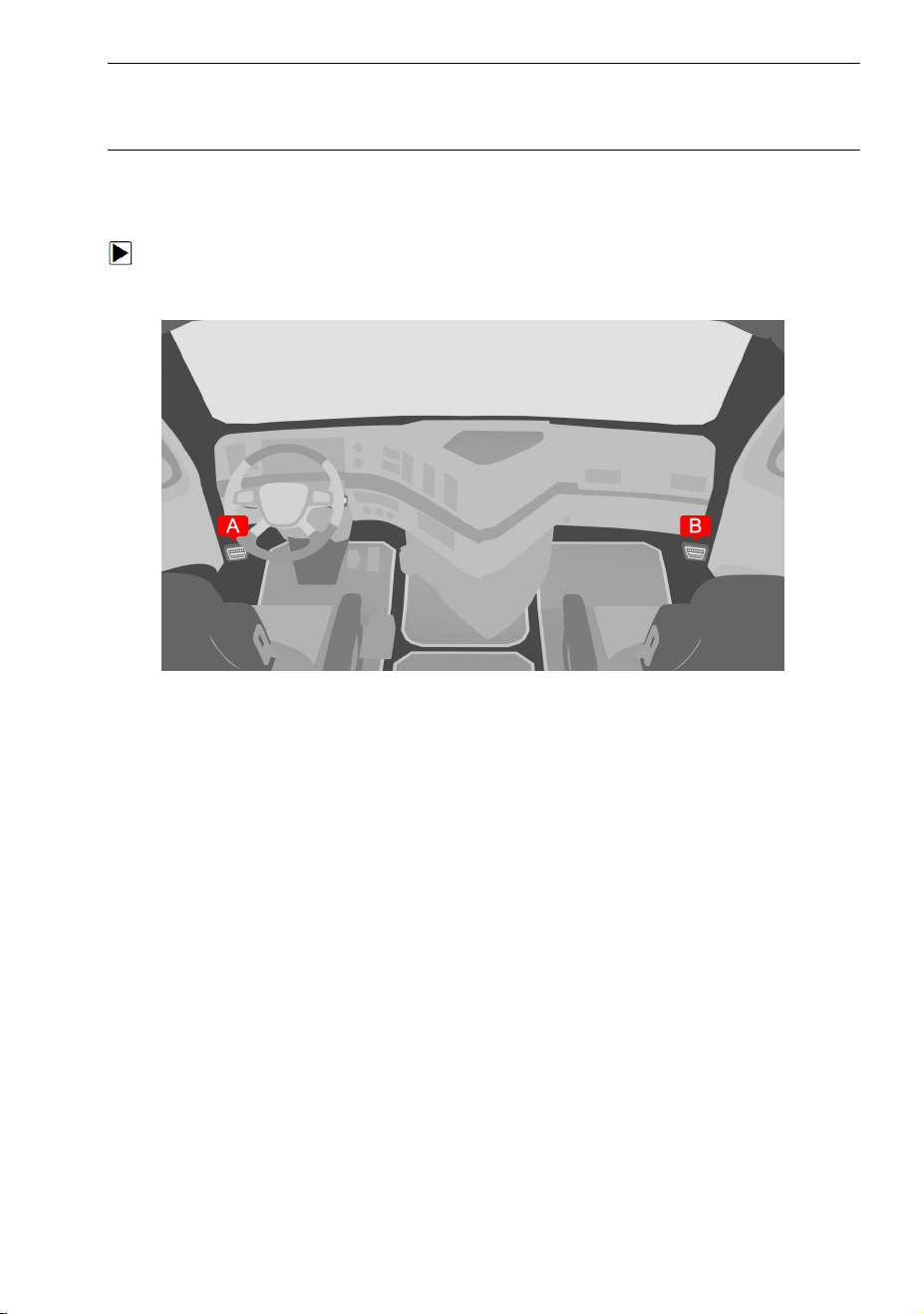
8.1 Vehicle Connection
To connect to vehicle:
1. Locate the data link connector (DLC). The DLC is generally located under the
dash on the driver side of the vehicle.
Figure 8-1 Sample Vehicle Connection Screen
2. Attached the diagnostic cable to the scanner and tighten the captive screws to
ensure good connection.
3. Connect a correct adapter to the data cable according to the vehicle being
serviced and plug it into the vehicle DLC.
4. Switch the ignition key to the ON position.
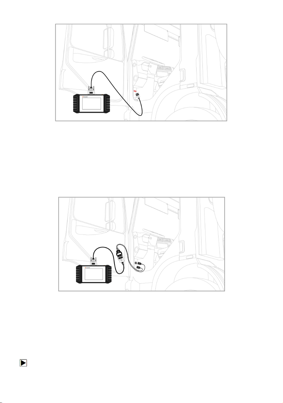
The following are instructions for the two connection methods:
Connection Of Standard OBD-II Interface:
Vehicles connected using the standard OBD-II interface only need to use the
integrated main test line OBD connector and no other connectors are
required:
30
HD500 User's Manual V1.3
Figure 8-2 Sample Connection Of Standard OBD-II Interface Screen
Connection Of Non OBD-II:
Vehicles with non-standard OBD-II interface need to connect the main test
line to the corresponding dedicated connector:
Figure 8-3 Sample Connection Of Non OBD-II Interface Screen
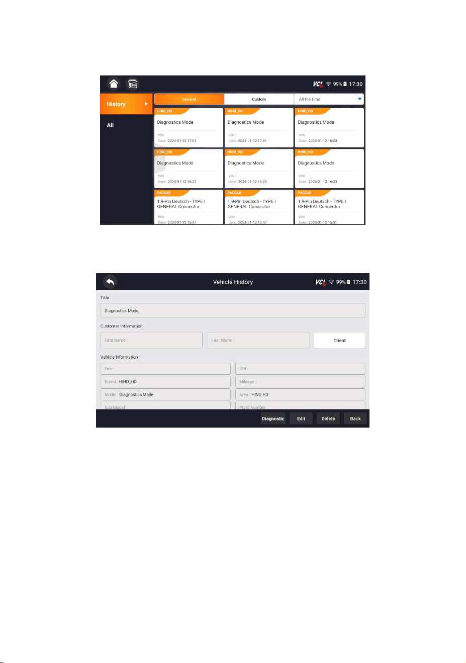
8.2 Vehicle History
Vehicle History keeps records of tested vehicles and allows restarting the diagnosis
of a vehicle without the need to do vehicle identification again.
To identify a vehicle by Vehicle History:
31
HD500 User's Manual V1.3
1. Select Diagnostic from home screen of the HD500 application.
2. Select History button at the top of the diagnostic page and the diagnostic
records will display.
Figure 8-4 Sample History Record Screen
3. Choose the vehicle model you want to test from the list.
4. Click the Diagnostic button at the bottom bar to go to vehicle test page.
Figure 8-5 Sample History Record Screen
9 Diagnosis
This section illustrates how to use the scanner to read and clear diagnostic trouble
codes, view live data readings and ECU information on Engine, ABS, Transmission,
perform special functions such as DPF regeneration, Injector Cutoff, Limits and ABS,
and perform vehicle services and maintenance on multiple brands.
The menu consists of two parts:
● Diagnosis
● Service

32
HD500 User's Manual V1.3
Figure 9-1 Sample Diagnostic Menu Screen
9.1 Vehicle Identification
When you completed the identification of vehicle, you have to identify the control
modules installed in the vehicle. There are two ways to identify the controllers
installed in a truck:
● Quick Scan
● Control Modules
Figure 9-2 Sample Diagnosis Screen
NOTE
Not all identify options listed above are applicable to all vehicles. Available options
may vary by the year, model, and make of the test vehicle.
33
HD500 User's Manual V1.3
9.1.1 Quick Scan
Quick Scan performs an automatic system test to determine which control
modules are installed on the vehicle and provides diagnostic trouble codes (DTCs)
overview. Depending on the number of control modules, it may take a few minutes
to complete the test.
To perform an automatic system scan:
1. Press Quick Scan option to start.
2. To pause the scan, press the Pause button on the screen.
Figure 9-3 Sample Quick Scan Screen
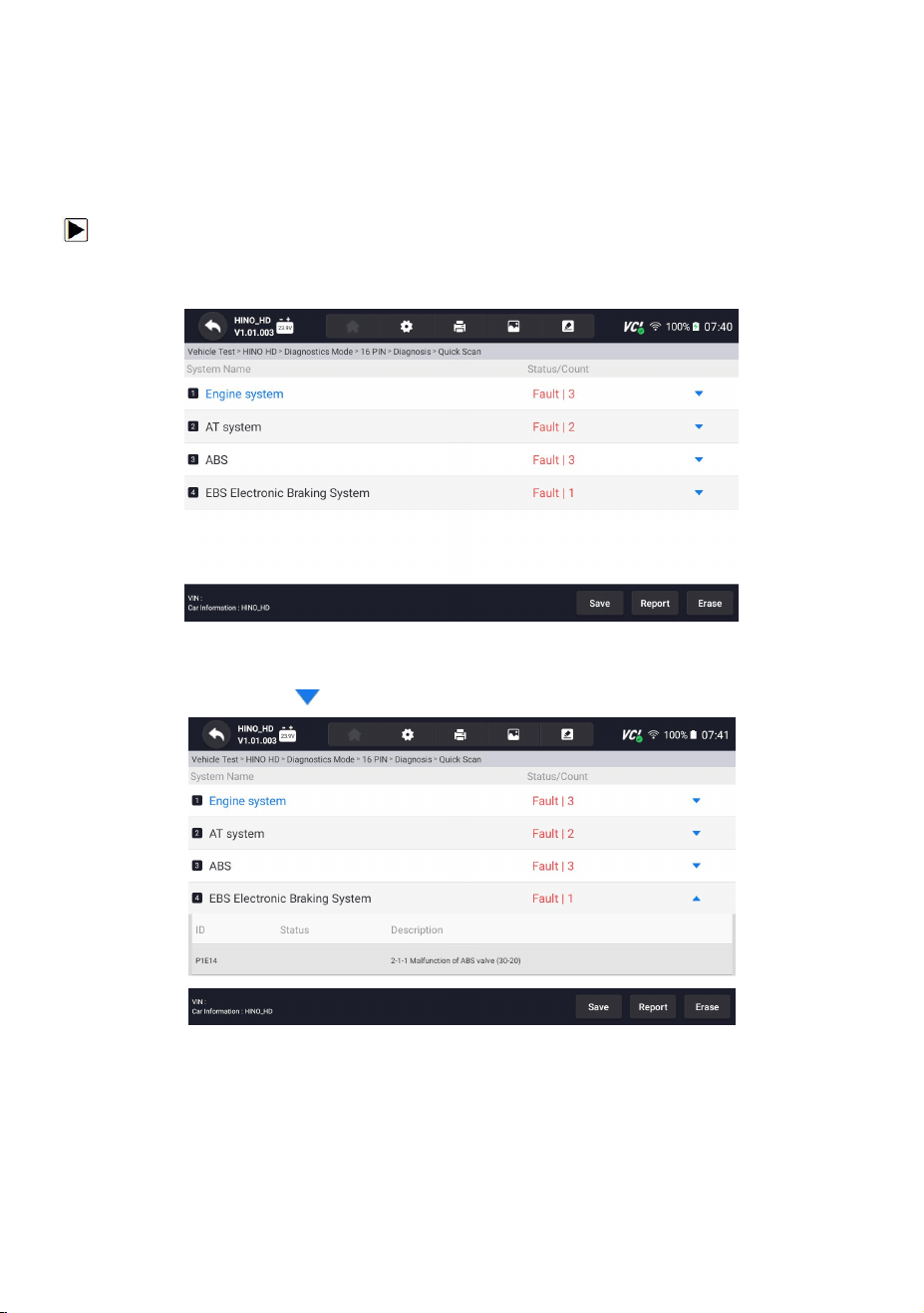
3. At the end of successful automatic controller scan, a menu with a list of DTC
displays and click button to the right to view DTC descriptions.
Figure 9-4 Sample Quick Scan Complete Screen
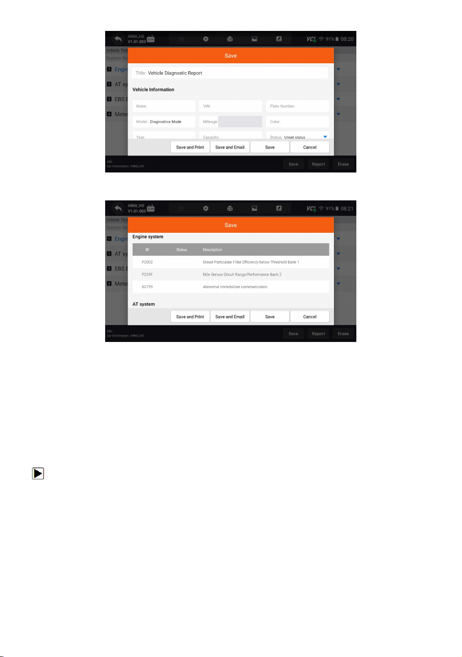
4. Press Report to create an overview of installed control units and their system
status, or press Save to save the report. Press Erase to clear the information.
34
HD500 User's Manual V1.3
Figure 9-5 Sample DTC Save Screen
Figure 9-6 Sample Save Screen
5. When running auto scanning, you can press Pause and select the system you
would like to test. When the scanner has established connection with the vehicle,
the Function Menu displays.
9.1.2 Control Modules
Control Modules displays all controllers available of the vehicle manufacturer. The
controllers listed on the menu do not mean that they are installed on the vehicle. It
is useful for technicians who are familiar with the vehicle specifications.
To select a system to test:
1. Press Control Modules from the menu and a controller menu displays.

35
HD500 User's Manual V1.3
Figure 9-7 Sample Control Modules Screen
2. Select a system to test. When the scanner has established connection with the
vehicle, the Function Menu displays.
Figure 9-8 Sample Function Menu Screen
9.2 Diagnostic Operations
After a system is selected and the scanner establishes communication with the
vehicle, the Function Menu displays. Generally the menu options are:
● ECU Information
● Read Codes
● Clear Codes
● Live Data
● Active Test
NOTE
36
HD500 User's Manual V1.3
Not all function options listed above are applicable to all vehicles. Available options
may vary by the year, model, and make of the test vehicle.
9.2.1 ECU Information
ECU Information screen displays the identification data of the control module
under test, such as the control module identification string and the control module
coding.
To read ECU information:
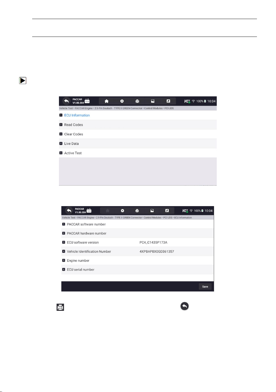
1. Press ECU Information from Select Diagnostic Function menu.
Figure 9-9 Sample Function Menu Screen
2. A screen with detailed information of the selected control module displays.
Figure 9-10 Sample ECU Information Screen
3. Press to print the information if need be. Press to exit.
4. Press Save to store ECU information screen and Press OK to complete save or
Press Cancel to give up.

37
HD500 User's Manual V1.3
Figure 9-11 Sample ECU Information Save Screen
9.2.2 Read Codes
Read Codes menu lets you read trouble codes found in the control unit.
To read codes from a vehicle:
1. Press Read Codes from Select Diagnostic Function menu. A code list including
code number and its description displays. The red icon means there is help
information available for the code. The green icon means there is freeze
frame available.
Figure 9-12 Sample Trouble Code Screen
● Freeze Frame - select one fault code from the code list and click Freeze Frame
button at the bottom bar. The screen will display freeze frame detail data, a
snapshot of critical vehicle operating conditions automatically recorded by the
on-board computer at the time of the DTC set. It is a good function to help
determine what caused the fault.
● Help - select one fault code from the code list and click Help button on the screen.
The screen will display the detailed descriptions about the fault code and repair
guide.
38
HD500 User's Manual V1.3
2. Slide up and down to view additional information when necessary.
3. Press Save to store DTC information. Press to print the information if need
be. Press to exit.
9.2.3 Clear Codes
Clear Codes menu lets you to clear all current and stored DTCs from a selected
control module. Also it erases all temporary ECU information, including freeze
frame, so make sure that the selected system is completely checked and serviced
by technicians and no vital information will be lost before clearing codes.
NOTE
● To clear codes, make sure that the ignition key is switched to ON with the engine
off.
● Clear Codes does not fix the problem that caused the fault! DTCs should only be
erased after correcting the condition(s) that caused them.
To clear codes:
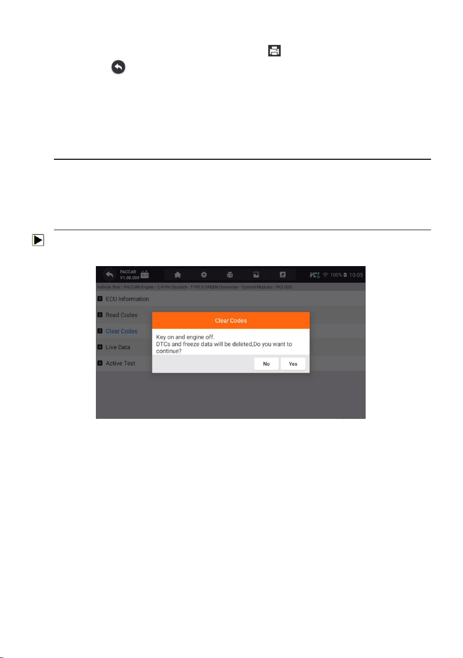
1. Press Clear Codes from Select Diagnostic Function menu.
Figure 9-13 Sample Function Menu Screen
2. Follow the on-screen instructions and answer questions about the vehicle being
tested to complete the procedure.
3. Check the codes again. If any codes remain, repeat the Clear Codes steps.
9.2.4 Live Data
Live Data menu lets you view real time PID data in text and plot formats, learn
good sensor data and compare them with faulty data, and record live data from a
selected vehicle electronic control module.
There are two ways to select the PID data of control module:
● All Data
● Custom List
39
HD500 User's Manual V1.3
Figure 9-14 Sample Function Menu Screen
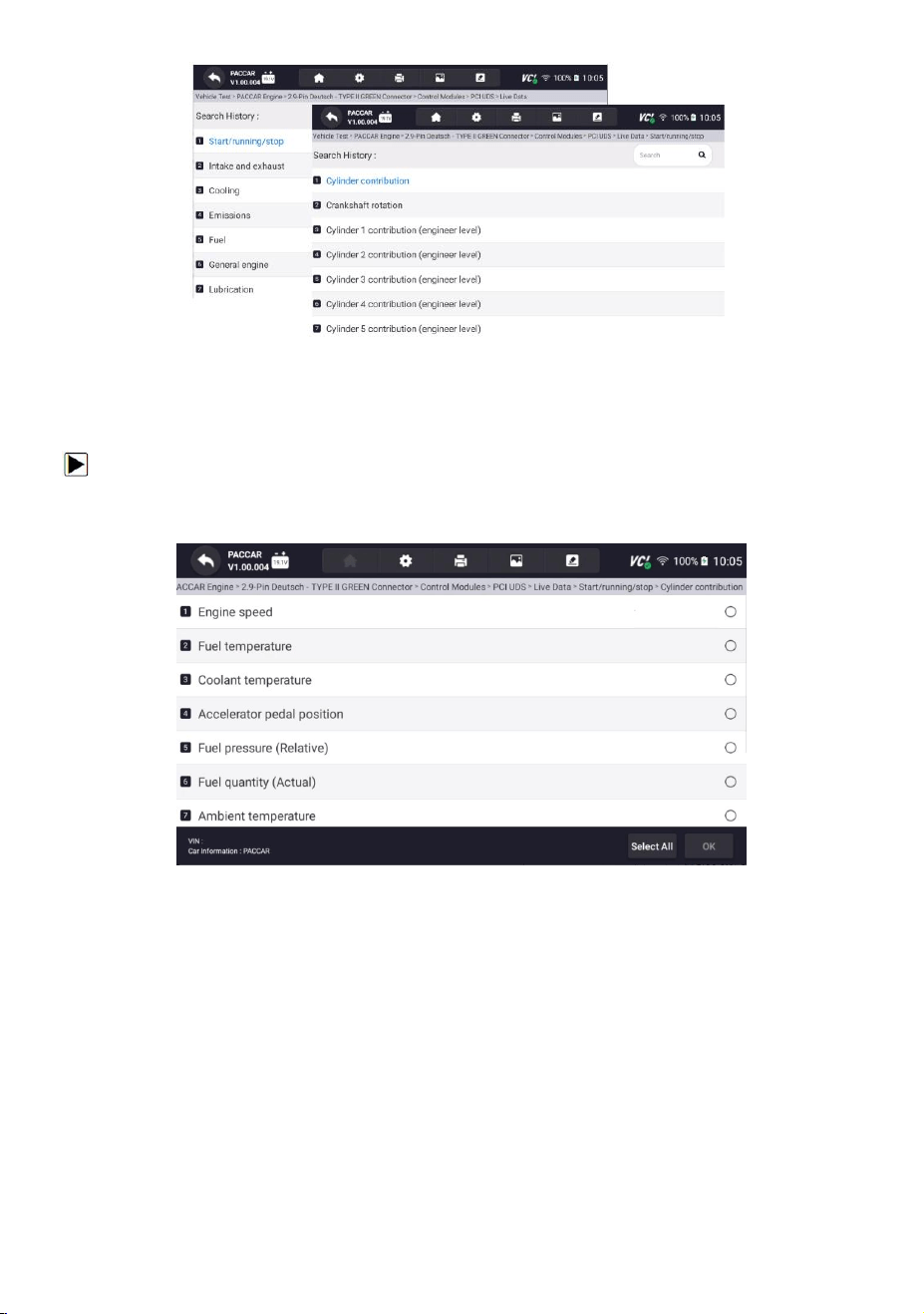
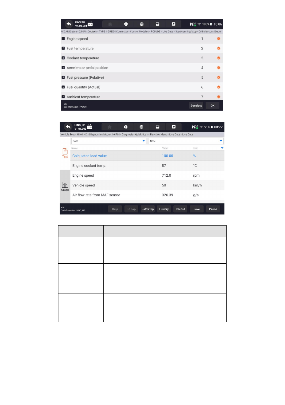
9.2.4.1 All Data
All Data menu lets you view all live PID data from a selected control module.
To view all live PID data:
1. Press Select ALL for select all live PID data and press Deselect ALL to deselect all
items.
Figure 9-15 Sample Function Menu Screen
2. Press OK to complete the selection and all readings will be displayed in text
format by default.
40
HD500 User's Manual V1.3
Figure 9-16 Sample Live Data Selection Screen
Figure 9-17 Sample Live Data Screen
Name
Description
Help
To provide help information of a PID
To Top
To move a data line to the top of Data List screen
History
To view the previous live data records or test
reports
Record
To make record of live data
Save
To save live data of current frame
Pause
To stop recording live data
Table 9-18 Live Data Screen Button Table
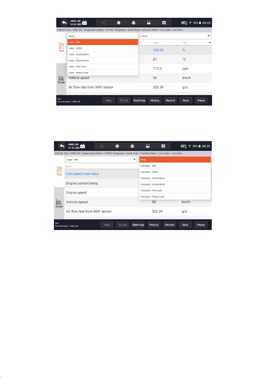
● Learn Mode: gives you the ability to learn good live sensor data values during
idle, KEKO, acceleration, deceleration, part load and heavy load on each vehicle
comes into your shop and records them for future reference. Click the
dropdown list at the upper left of the screen to enter to choose a working
condition to learn.
41
HD500 User's Manual V1.3
Figure 9-19 Sample Learn Mode Screen
● Compare Mode - If that vehicle comes in is with a problem, you can easily
compare the faulty sensor and parameter readings to the good readings, and
you will be alarmed when a faulty sensor reading is detected.
Figure 9-20 Sample Live Data Screen
3. Swipe the screen up and down to view additional information when necessary.
4. To move a data line to the top of Data List screen, just tap the line to select and
then press the button To Top. To view data records or test reports, and press
the button History. To make records of live data, just tab the button Record, and
press Pause to stop recording at any time. To save the data, tap the Save icon.
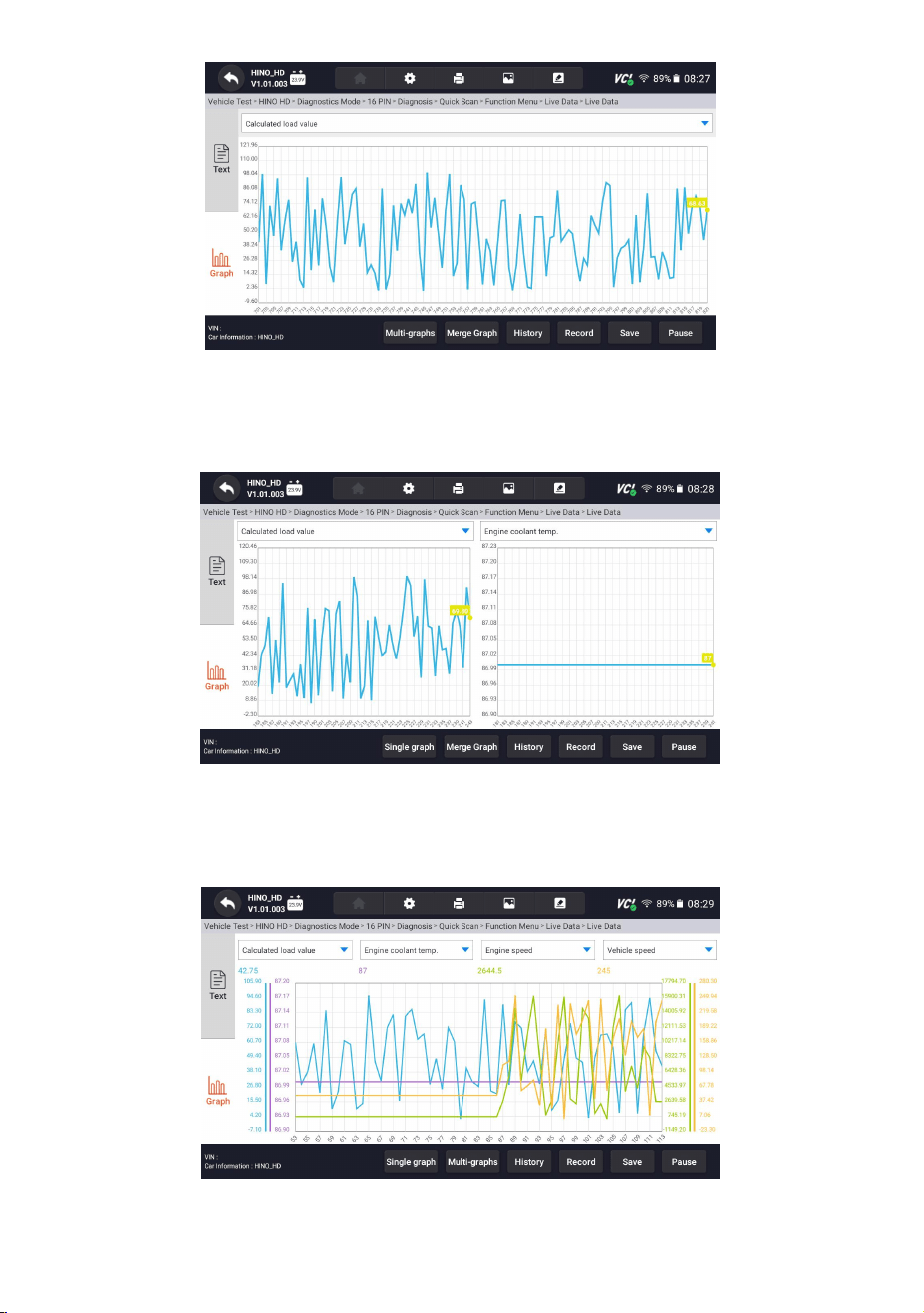
5. To view live PID in graph format, press the tab Graph, and the plot displays. To
view another PID plot, tab the name of a plot and a list of available PIDs display.
Select one from the dropdown box and the plot changes to the newly selected
PID.
42
HD500 User's Manual V1.3
Figure 9-21 Sample PID Graph Screen
● Multi-graphs: displays the parameters in waveform graphs, giving you the ‘real
picture’ of what’s going on in the vehicle. You can view up to 4 parameter
graphs simultaneously.
Figure 9-22 Sample Multi-graphs Screen
● Merge Graph: merges multiple PID plots into one coordinate, so you can easily
see how they affect each other, providing you with the most comprehensive and
functional look at live data possible.
Figure 9-23 Sample Merge Graph Screen
43
HD500 User's Manual V1.3
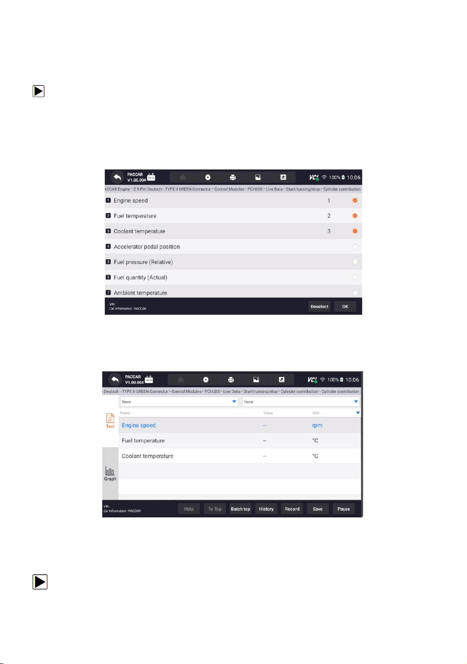
9.2.4.2 Custom List
Custom List menu lets you to minimize the number of PIDs on the data list and
focus on any suspicious or symptom-specific data parameters.
To create a custom data list:
1. Press Custom List from the menu to display all available parameters from the
selected control module.
2. The custom data stream selection screen displays. Tap the lines you wish to
select. The numbers showing on the right side indicates the order of selection
and the live data will show as this order.
Figure 9-24 Sample Custom List Selection Screen
3. To deselect an item, tap the line again. Alternatively, tap SELECT ALL or Deselect
ALL to select or deselect all items at once.
4. Press OK to complete the selection, and all selected items display.
Figure 9-25 Sample Live Data Screen
9.2.4.3 Record data
Data Record is for recording the running data of the current control module.
To Record Data
44
HD500 User's Manual V1.3
1. Press Record button to record all selected live data, then it will show the record
time and frames.
Figure 9-26 Sample Live Data Record Screen
2. Press Stop button to create a record, then press OK to save the record into Data
Playback of Data Manager.
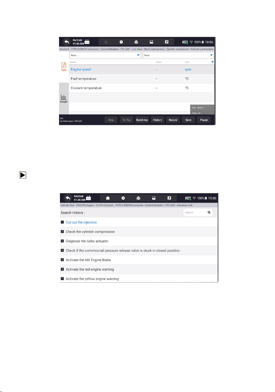
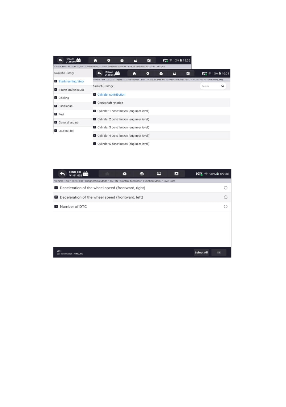
9.2.5 Active Test
To make a Active Test:
1. Please click "Active Test" in the Diagnostic Functions menu.
Figure 9-27 Sample Active Test Search History Interface
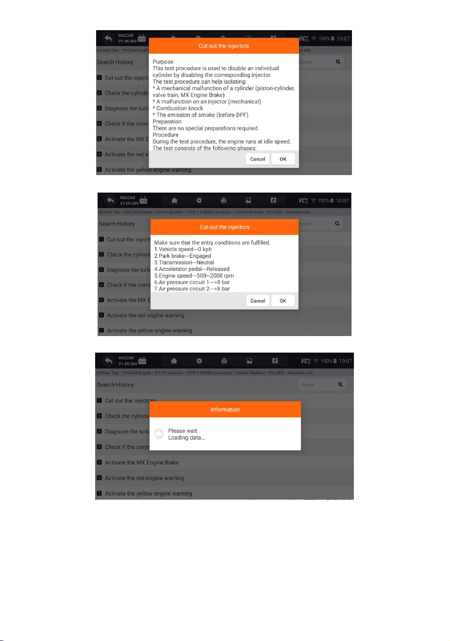
2. It will displays an interface for prompting the operation purpose and process of
the selected control module.
45
HD500 User's Manual V1.3
Figure 9-28 Sample Purpose And Process Prompt Interface
Figure 9-29 Sample Checking Vehicle Information Interface
Figure 9-30 Sample Data Loading Interface
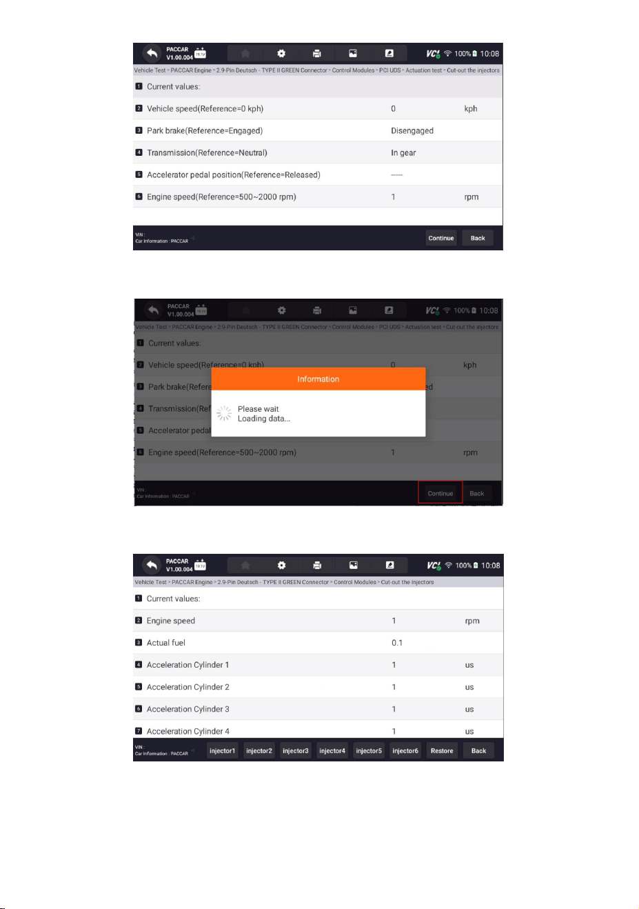
3. Test according to the selected module and output the final test results.
46
HD500 User's Manual V1.3
Figure 9-31 Sample Test Results Interface
4. Please click the Continue on the interface to obtain further test data.
Figure 9-32 Sample Further Testing Data of The Interface
5.Get further test data on the interface.
Figure 9-33 Sample Test Result Interface

47
HD500 User's Manual V1.3
9.3 Service
The Service section is specifically designed to provide you with quick access to
various scheduled service and maintenance features of your vehicle's systems.
To make a Service:
1.Please enter the diagnostic page, select the truck model, and click the Service
option below.
Figure 9-34 Sample Diagnostic Menu Selection Interface
2.Please select the service that needs to be performed. Follow the on-screen
instructions to make the correct selections and actions to complete the test.
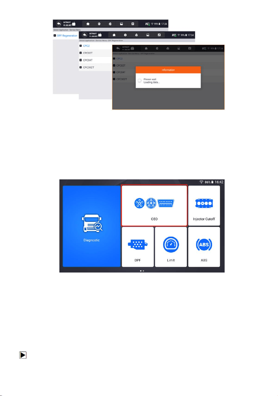
● Ash Service Regeneration
● DPF Regeneration
Figure 9-35 Sample Service Selection Interface
48
HD500 User's Manual V1.3
Figure 9-36 Sample Service Selection Interface
10 OBD
OBD refers to the on-board diagnostic system used to monitor and diagnose the
working status and fault information of the vehicle. It can help car owners and
technicians to quickly locate and solve vehicle faults and improve vehicle
performance and reliability.
Figure 10-1 Sample OBD Entry Interface
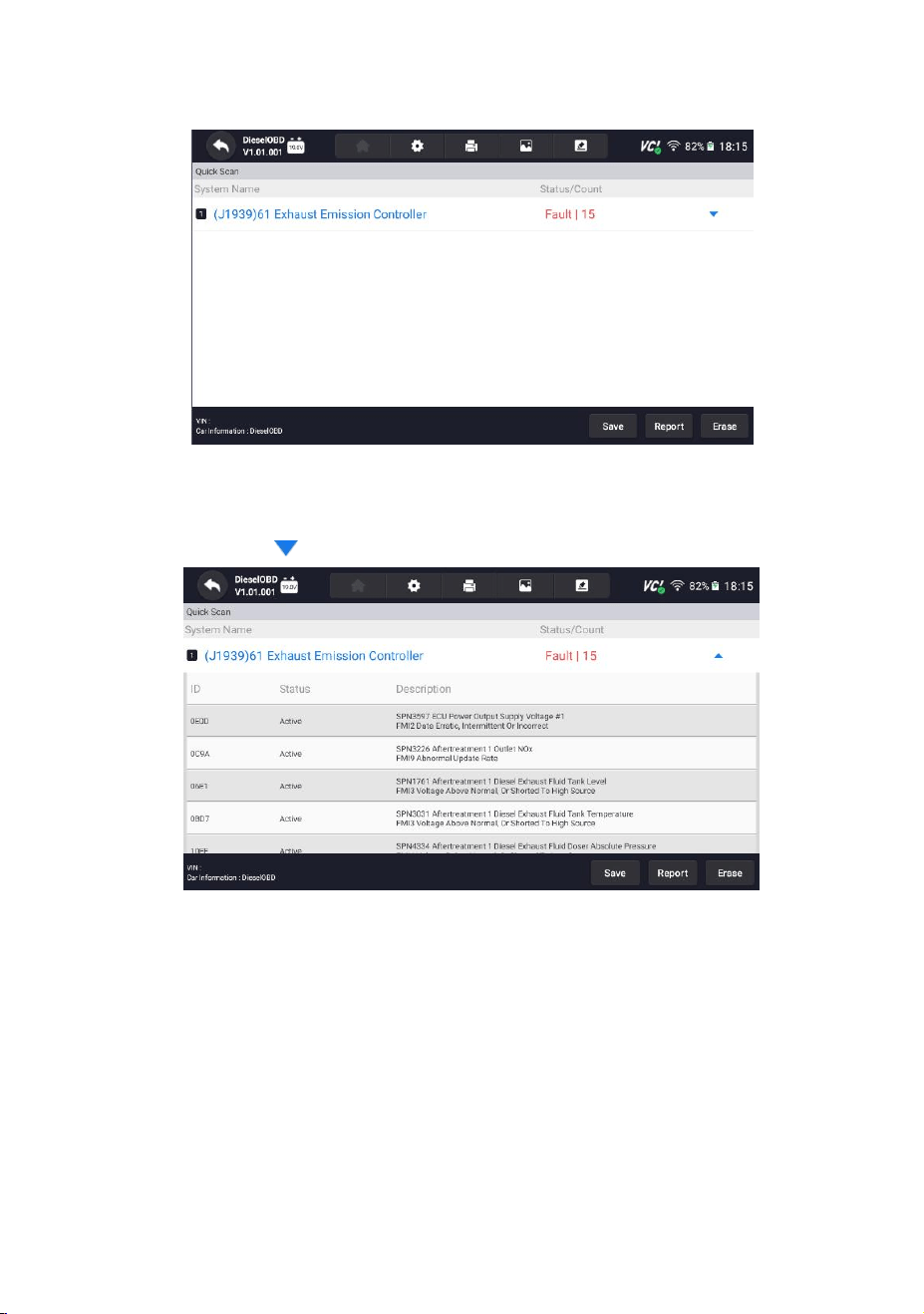
10.1 Quick Scan
Quick Scan performs an automatic system test to determine which control modules
are installed on the vehicle and provides diagnostic trouble codes (DTCs) overview.
Depending on the number of control modules, it may take a few minutes to
complete the test.
To perform an automatic system scan:
49
HD500 User's Manual V1.3
1. Press Quick Scan option to start.
2. To pause the scan, press the Pause button on the screen.
Figure 10-2 Sample Quick Scan Interface
3. At the end of successful automatic controller scan, a menu with a list of DTC
displays and click button to the right to view DTC descriptions.
Figure 10-3 Sample Quick Scan Interface
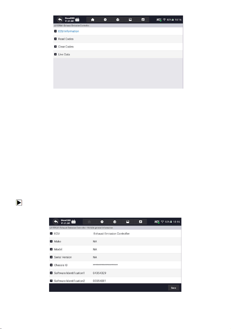
4. When the scanner has established connection with the vehicle, the Function
Menu displays.
50
HD500 User's Manual V1.3
Figure 10-4 Sample Function Menu displays Interface
10.2 Diagnostic Operations
After a system is selected and the scanner establishes communication with the
vehicle, the Function Menu displays. Generally the menu options are:
● ECU Information
● Read Codes
● Clear Codes
● Live Data
10.2.1 ECU Information
ECU Information screen displays the identification data of the control module
under test, such as the control module identification string and the control module
coding.
To read ECU information:
1. Press ECU Information from Select Diagnostic Function menu.
Figure 10-5 Sample ECU Information Screen
51
HD500 User's Manual V1.3
2. Press to print the information if need be. Press to exit.
3.Press Save to store ECU information screen and Press OK to complete save or
Press Cancel to give up.
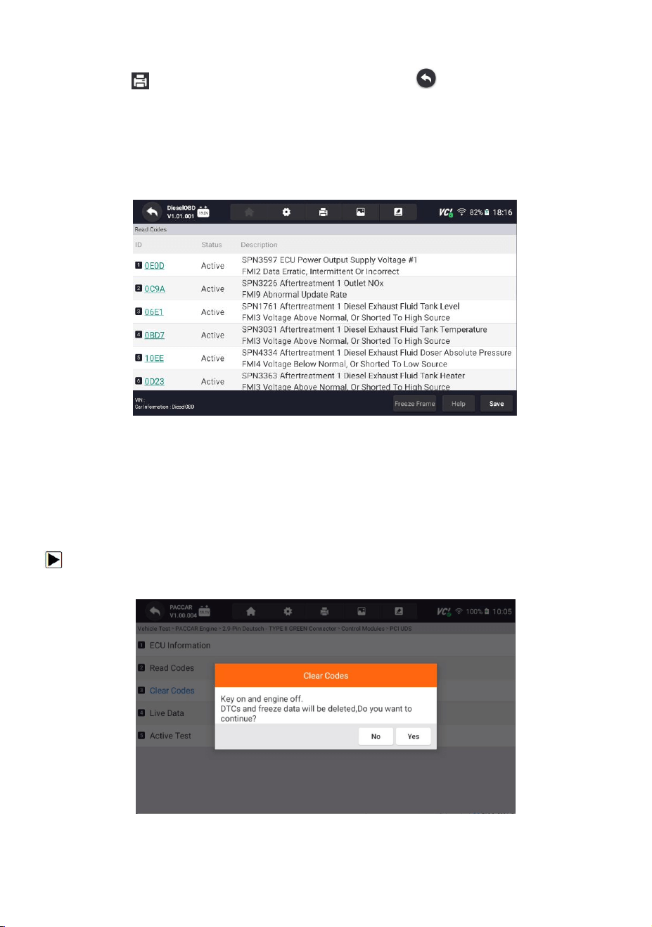
10.2.2 Read Codes
Figure 10-6 Sample Read Codes Screen
10.2.3 Clear Codes
Clear Codes menu lets you to clear all current and stored DTCs from a selected
control module. Also it erases all temporary ECU information, including freeze
frame, so make sure that the selected system is completely checked and serviced
by technicians and no vital information will be lost before clearing codes.
To clear codes:
1. Press Clear Codes from Select Diagnostic Function menu.
Figure 10-7 Sample Clear Codes Screen
52
HD500 User's Manual V1.3
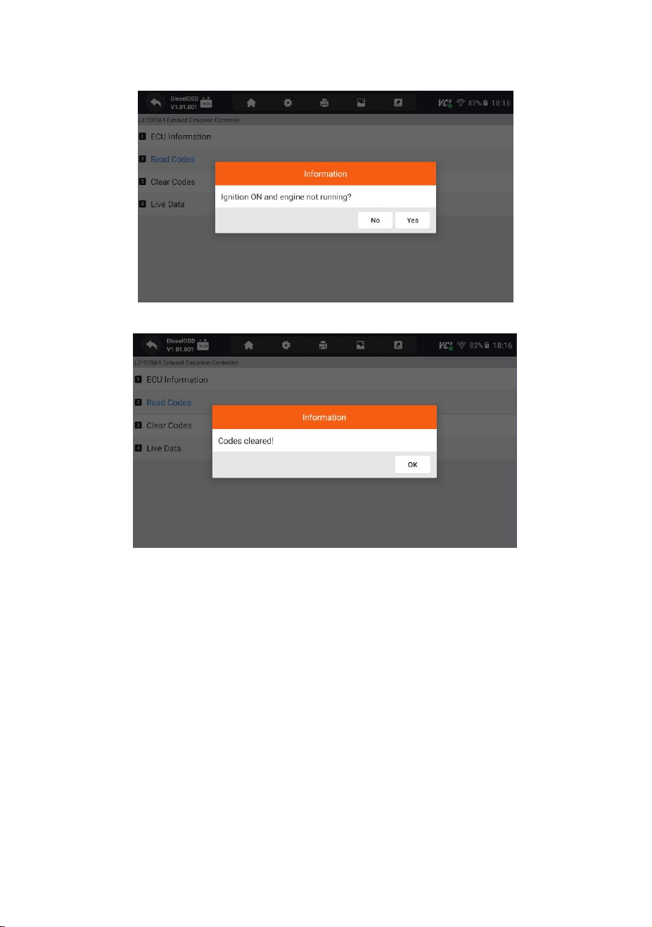
2. Follow the on-screen instructions and answer questions about the vehicle being
tested to complete the procedure.
Figure 10-8 Sample Ask For Confirmation Screen
Figure 10-9 Sample Codes cleared Screen
11 ABS
ABS is also called anti-lock braking system. Its function is to prevent the wheels from
completely locking. ABS will connect a speed sensor to each wheel. When the sensor
detects that the wheel is about to lock, the modulator will immediately release the
brake pads of some wheels. , so that the wheels will be allowed to rotate indirectly
during braking.
53
HD500 User's Manual V1.3
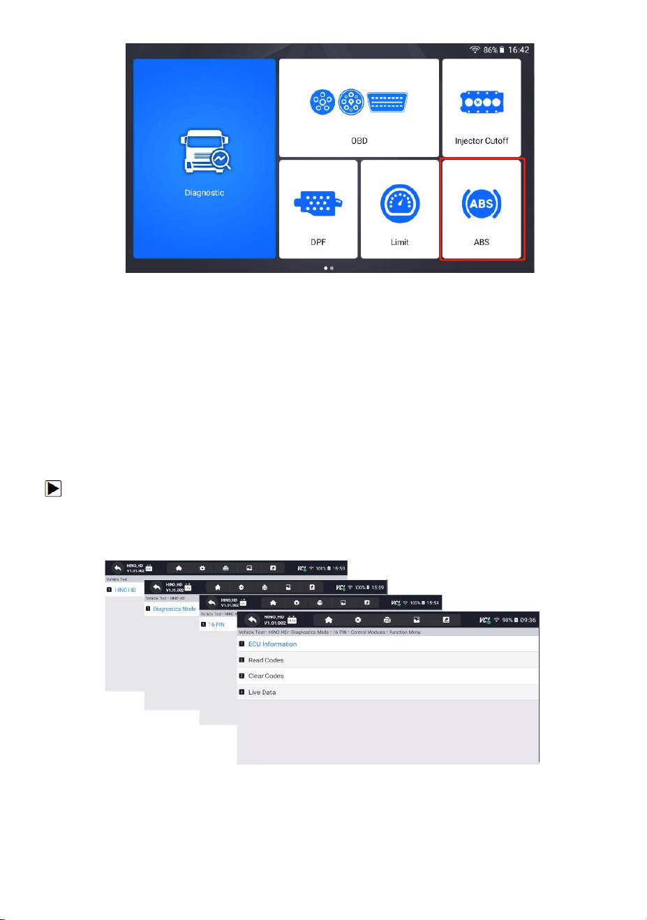
Figure 11-1 Sample ABS Entry Interface
11.1 Vehicle Identification
When you completed the identification of vehicle, you have to identify the control
modules installed in the vehicle.
Control Modules displays all controllers available of the vehicle manufacturer. The
controllers listed on the menu do not mean that they are installed on the vehicle. It
is useful for technicians who are familiar with the vehicle specifications.
To select a system to test:
Enter the ABS page, select the truck model, and select the control modules in
sequence according to the page prompts.
Figure 11-2 Sample Control Modules Screen
54
HD500 User's Manual V1.3
NOTE
Not all identify options listed above are applicable to all vehicles. Available options
may vary by the year, model, and make of the test vehicle.
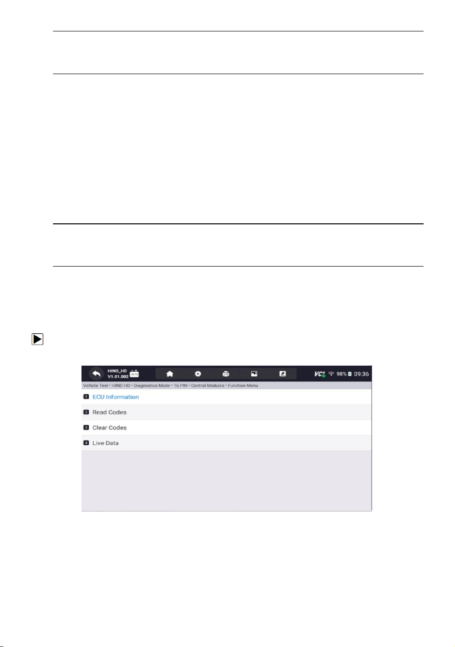
11.2 Diagnostic Operations
After a system is selected and the scanner establishes communication with the
vehicle, the Function Menu displays. Generally the menu options are:
● ECU Information
● Read Codes
● Clear Codes
● Live Data
NOTE
Not all function options listed above are applicable to all vehicles. Available options
may vary by the year, model, and make of the test vehicle.
11.2.1 ECU Information
ECU Information screen displays the identification data of the control module
under test, such as the control module identification string and the control module
coding.
To read ECU information:
1.Press ECU Information from Select Diagnostic Function menu.
Figure 11-3 Sample Function Menu Screen
2.A screen with detailed information of the selected control module displays.
55
HD500 User's Manual V1.3
Figure 11-4 Sample ECU Information Screen
3.Press to print the information if need be. Press to exit.
4.Press Save to store ECU information screen and Press OK to complete save or
Press Cancel to give up.
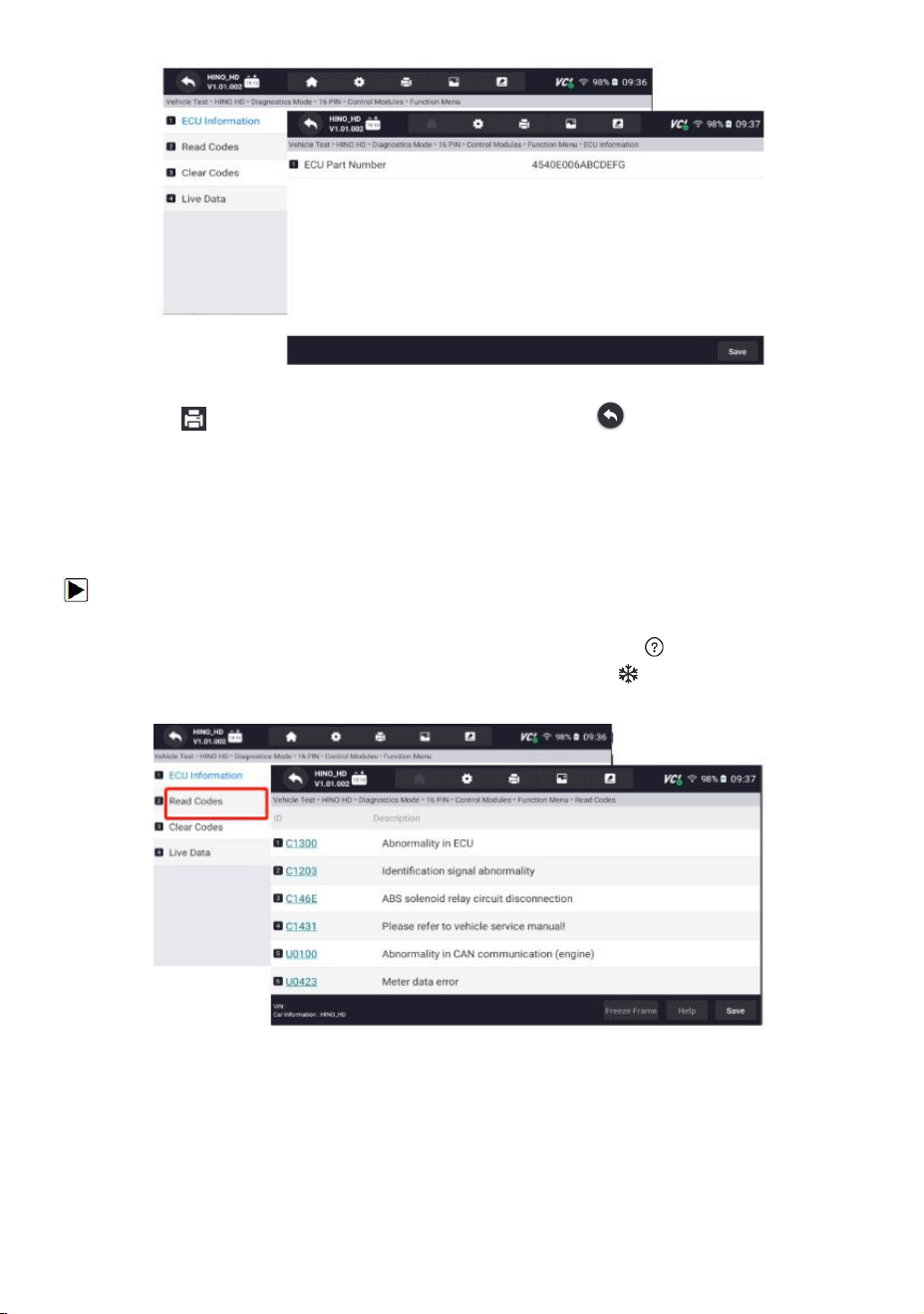
11.2.2 Read Codes
Read Codes menu lets you read trouble codes found in the control unit.
To read codes from a vehicle:
1.Press Read Codes from Select Diagnostic Function menu. A code list including
code number and its description displays. The red icon means there is help
information available for the code. The green icon means there is freeze
frame available.
Figure 11-5 Sample Trouble Code Screen
● Freeze Frame - select one fault code from the code list and click Freeze Frame
button at the bottom bar. The screen will display freeze frame detail data, a
snapshot of critical vehicle operating conditions automatically recorded by the
on-board computer at the time of the DTC set. It is a good function to help
determine what caused the fault.
56
HD500 User's Manual V1.3
● Help - select one fault code from the code list and click Help button on the screen.
The screen will display the detailed descriptions about the fault code and repair
guide.
2.Slide up and down to view additional information when necessary.
3.Press Save to store DTC information. Press to print the information if need
be. Press to exit.
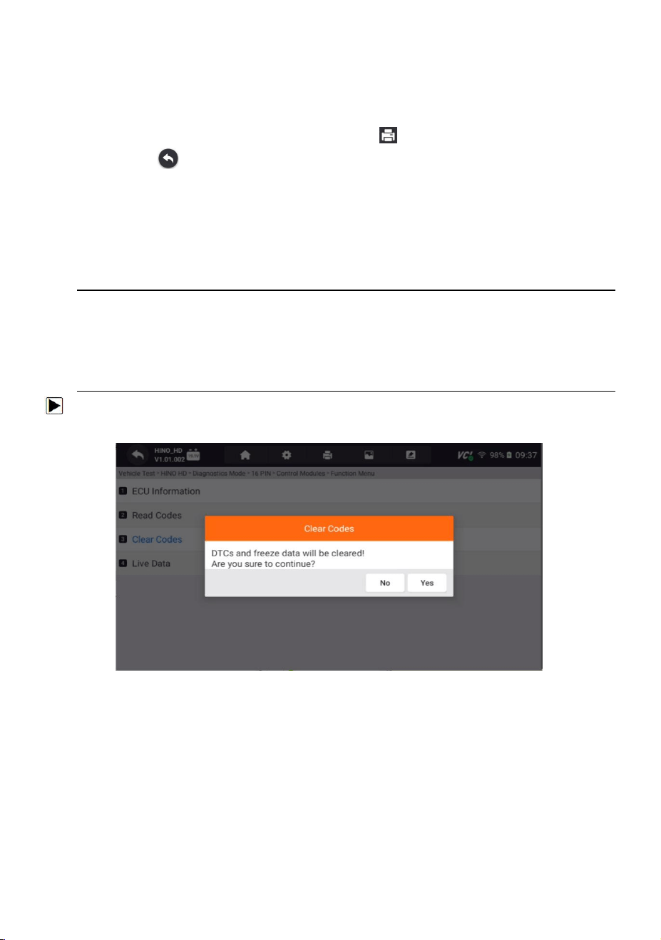
11.2.3 Clear Codes
Clear Codes menu lets you to clear all current and stored DTCs from a selected
control module. Also it erases all temporary ECU information, including freeze
frame, so make sure that the selected system is completely checked and serviced
by technicians and no vital information will be lost before clearing codes.
NOTE
● To clear codes, make sure that the ignition key is switched to ON with the engine
off.
● Clear Codes does not fix the problem that caused the fault! DTCs should only be
erased after correcting the condition(s) that caused them.
To clear codes:
1.Press Clear Codes from Select Diagnostic Function menu.
Figure 11-6 Sample Clear Code Screen
2.Follow the on-screen instructions and answer questions about the vehicle being
tested to complete the procedure.
3.Check the codes again. If any codes remain, repeat the Clear Codes steps.
11.2.4 Live Data
Live Data menu lets you view real time PID data in text and plot formats, learn
good sensor data and compare them with faulty data, and record live data from a
selected vehicle electronic control module.
57
HD500 User's Manual V1.3
There are two ways to select the PID data of control module:
● All Data
● Custom List
Figure 11-7 Sample Function Menu Screen
Figure 11-8 Sample Data Selection Screen
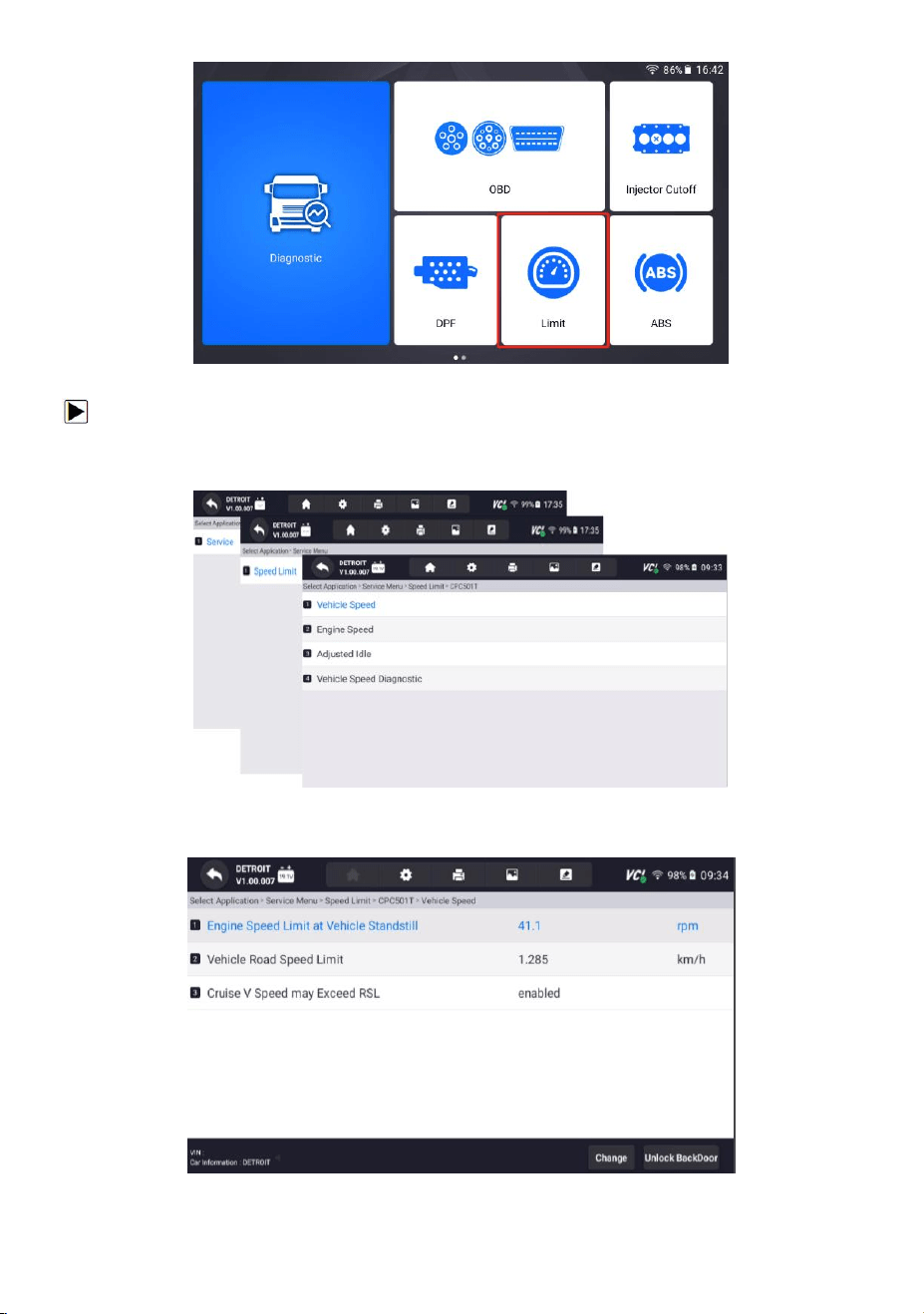
12 LIMIT
Speed limit setting Check and set the engine speed and the vehicle road speed limit
when the vehicle is stationary.
58
HD500 User's Manual V1.3
Figure 12-1 Sample LIMIT Function Entry Interface
To select a system to test:
1.Enter the LIMIT page, select the truck model, and select the control modules in
sequence according to the page prompts.
Figure 12-2 Sample Control Modules Screen
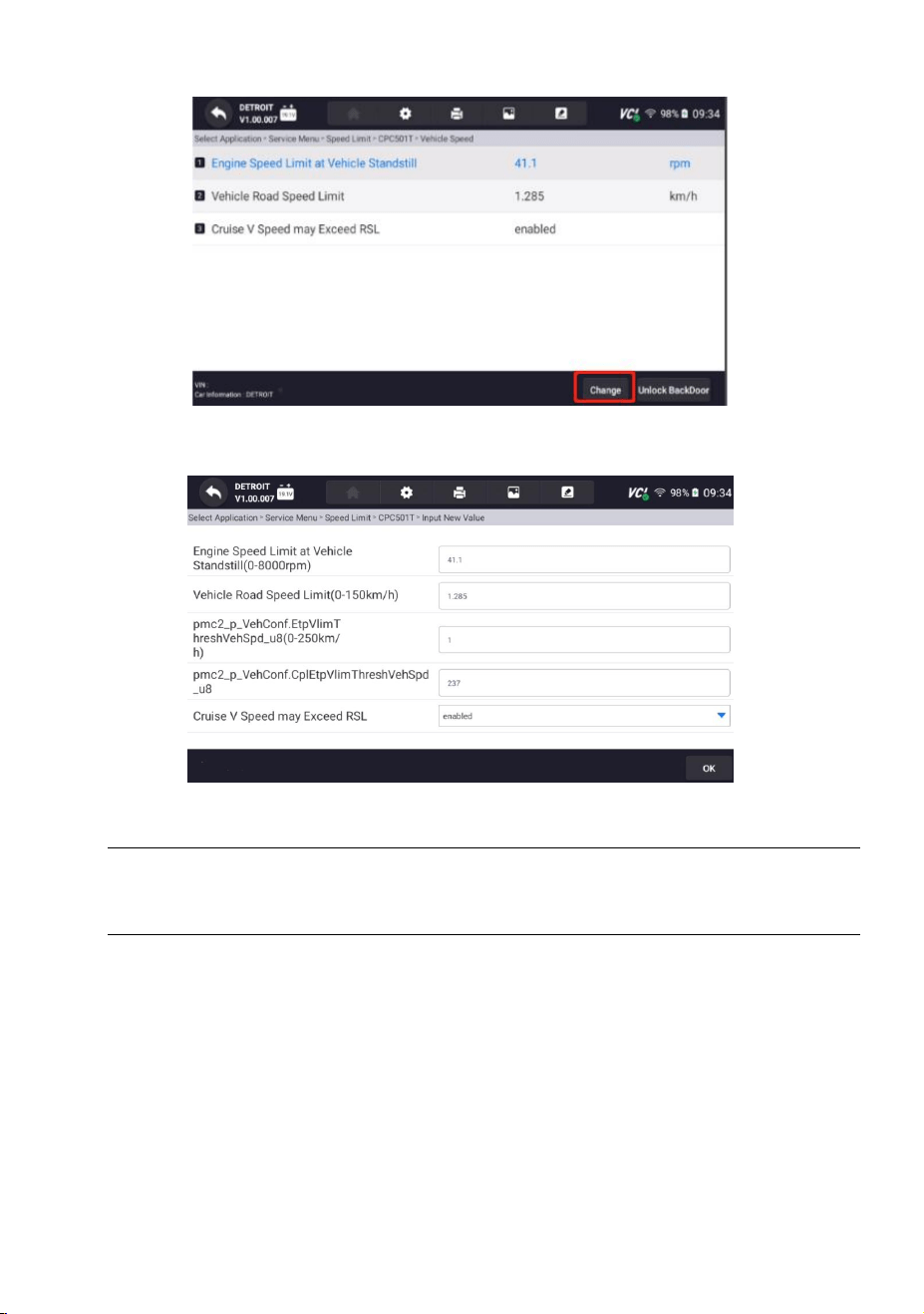
2.After the speed limit setting test is completed, the test results are displayed.
Figure 12-3 Sample Test Result Screen
59
HD500 User's Manual V1.3
3.Click "Change" in the lower right corner to modify the standard.
Figure 12-4 Sample Modifying The Standard Operation Entry Interface
4.Speed limit standard modification interface.
Figure 12-5 Sample Editing Interface
NOTE
Not all identify options listed above are applicable to all vehicles. Available options
may vary by the year, model, and make of the test vehicle.
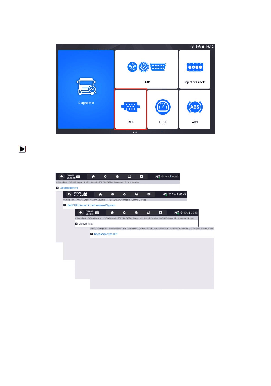
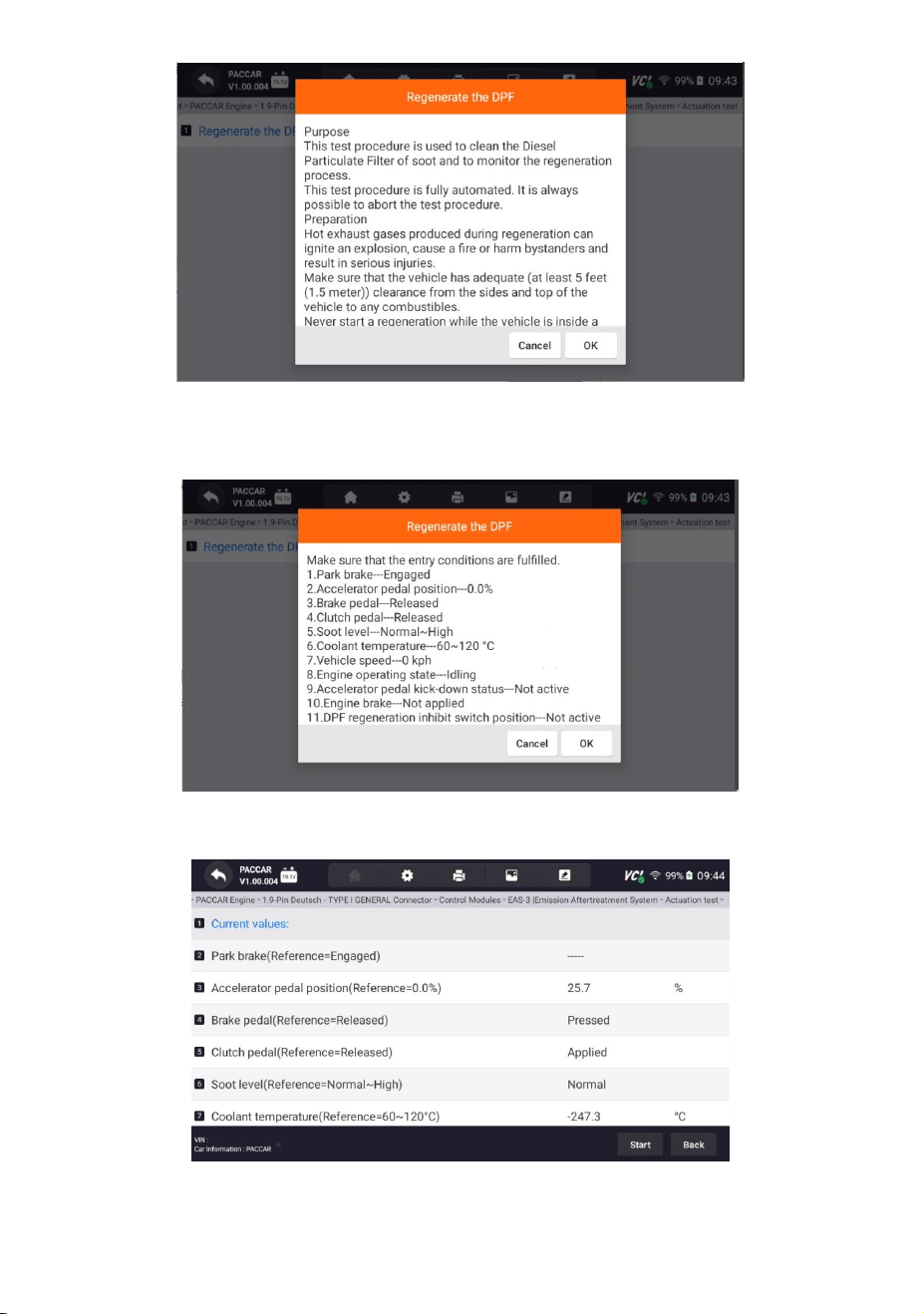
13 DPF
The flow resistance calculated by judging the DPF pressure difference is lower than
the calibrated limit. The low DPF pressure difference causes this fault. Check the
speed setting and set the engine speed and vehicle road speed limit when the
vehicle is stationary.
The purpose of this test procedure is to remove soot from the diesel particulate
filter and monitor the regeneration process. This testing process is fully automated.
60
HD500 User's Manual V1.3
Hot exhaust gases generated during the regeneration process may cause an
explosion, cause a fire or injure bystanders, resulting in serious injury. Make sure
vehicles have adequate (at least 5 feet (1.5 meters)) clearance.
Figure 13-1 Sample DPF Function Entry Interface
To select a system to test:
1.Please enter the DPF page, select the truck model and select the control module
in sequence according to the prompts.
Figure 13-2 Sample Control Modules Screen
2. Please according to the pop-up message to understand the purpose and process.
61
HD500 User's Manual V1.3
Figure 13-3 Sample Purpose And Process Interface
3.To Check whether the vehicle meets the conditions based on the pop-up
message.
Figure 13-4 Sample Checking Whether The Vehicle Meets The Conditions Interface
4.The test is completed and the test results are output.
Figure 13-5 Sample Test Results Interface
62
HD500 User's Manual V1.3
NOTE
Not all identify options listed above are applicable to all vehicles. Available options
may vary by the year, model, and make of the test vehicle.
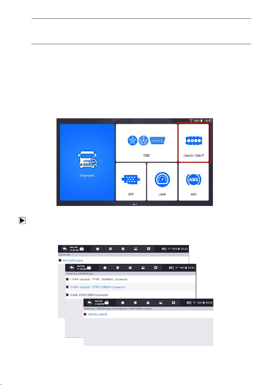
14 Injector cutoff
Principle of cylinder cut-off: When the engine is idling, the fuel injection or ignition
line of a certain cylinder is cut off, and then the performance of this cylinder is
judged by the working status of the engine to see whether the performance of this
cylinder is normal.
The purpose of this test procedure is to disable individual cylinders by disabling the
corresponding injector.
Figure 14-1 Sample Break Cylinder Test Entry Interface
To select a system to test:
1.Enter the Injector cutoff page, select the truck model and the control module in
sequence according to the prompts.
Figure 14-2 Sample Control Modules Screen
63
HD500 User's Manual V1.3
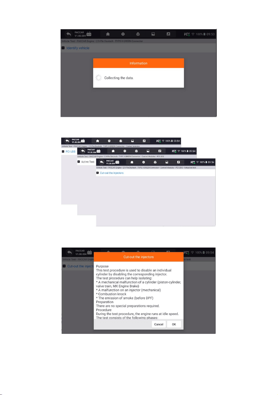
2.Waiting to collect loading data.
Figure 14-3 Sample Waiting Information Loading Interface
3.Please select the corresponding module according to the prompts.
Figure 14-4 Sample Control Modules Screen
4.To understand the purpose and process based on the pop-up message.
Figure 14-5 Sample Purpose And Process Interface
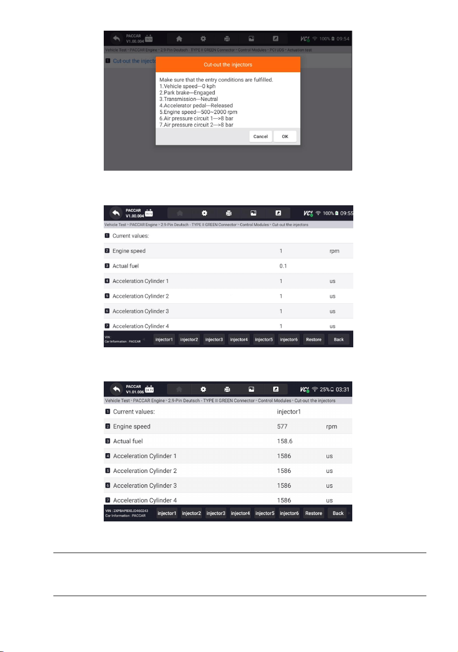
5.Check whether the vehicle meets the conditions based on the pop-up message.
64
HD500 User's Manual V1.3
Figure 14-6 Sample Checking Whether The Vehicle Meets The Conditions Interface
6.After test completed, the test results will output.
Figure 14-7 Sample Output Results Interface
7.Click on the bottom injector1-6 to output the results.
Figure 14-8 Sample Output Results Interface
NOTE
Not all identify options listed above are applicable to all vehicles. Available options
may vary by the year, model, and make of the test vehicle.
65
HD500 User's Manual V1.3
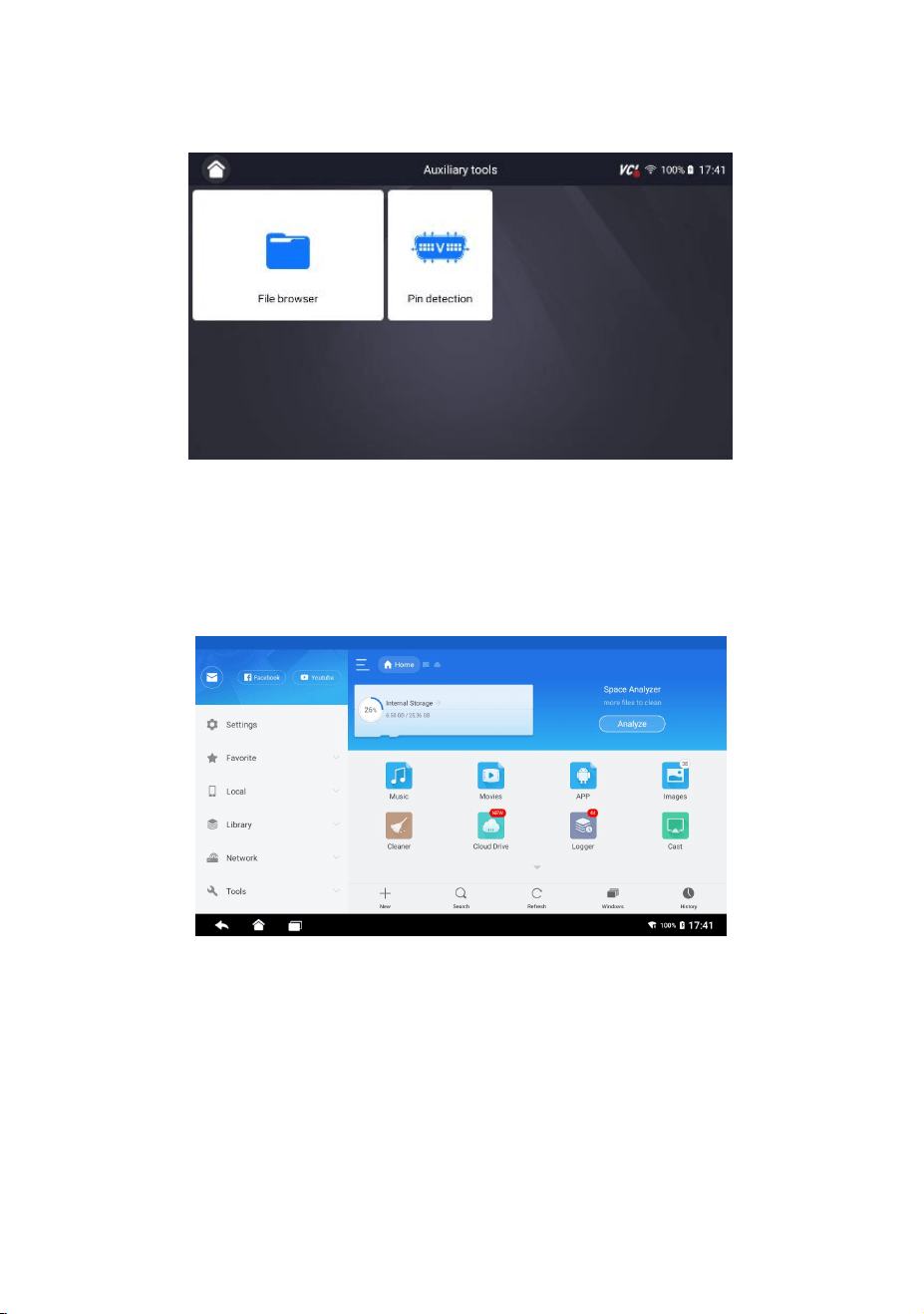
15 Auxiliary tools
Auxiliary tools :It’s mainly to store files and perform pin testing.
Figure 15-1 Sample Auxiliary Tools Interface
15.1 File browser
File storage mainly stores music, movies, APPs, images and other information in
the system, and records storage operations.
Figure 15-2 Sample File Storage Interface
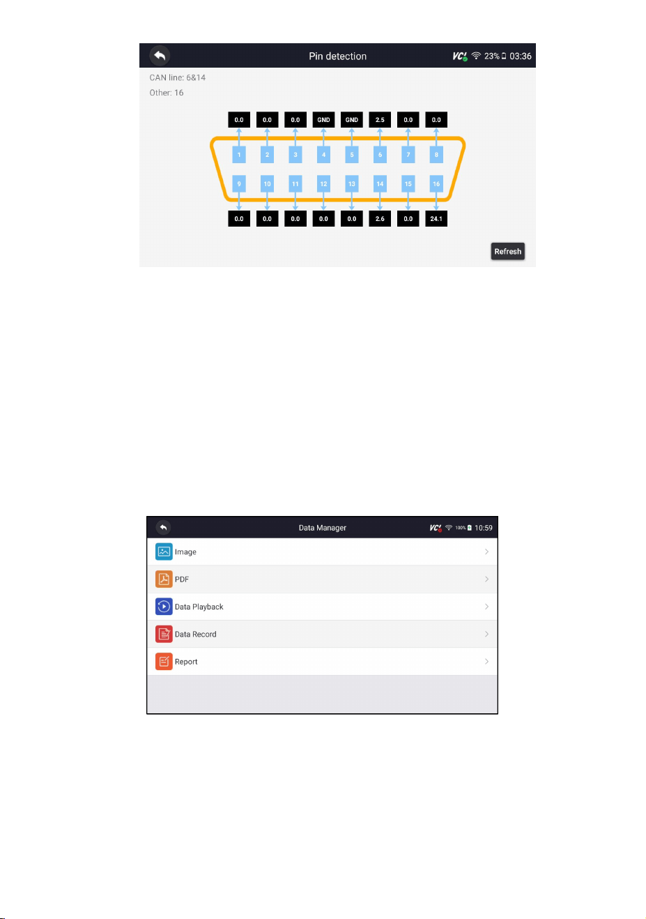
15.2 Pin detection
This function mainly measures the 16-pin voltage diagnostic interface of the OBD
and determines the pin positions of the K line and CAN line.
After connecting the vehicle OBD interface, click the main interface interface File
browser to select pin detection. As shown below:
66
HD500 User's Manual V1.3
Figure 15-3 Sample Pin Test Interface
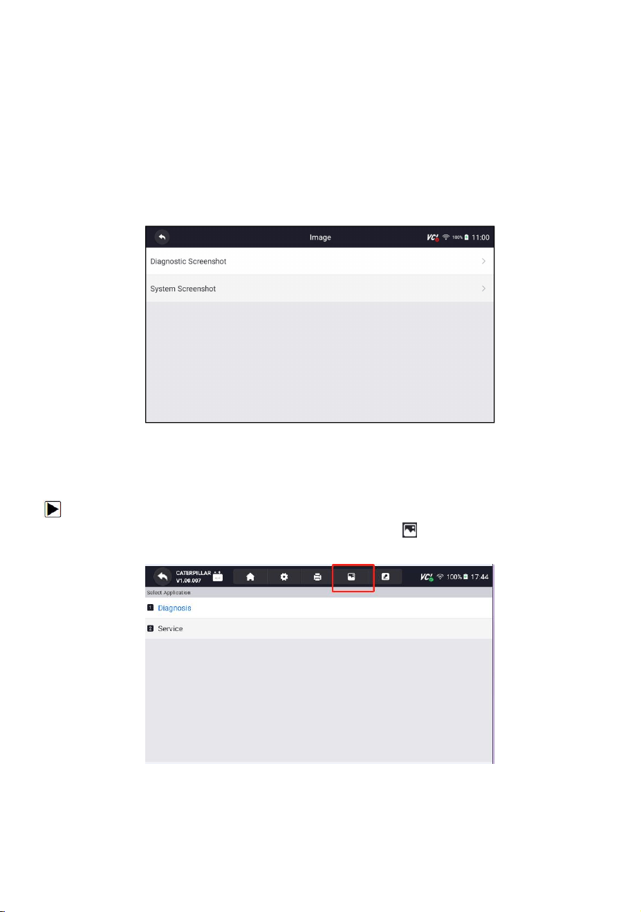
16 Data Manager
Data Manager menu let you review stored screenshots and test reports, playback
recorded live data and other saved files.
Typical menu options include:
● Image
● PDF
● Data Playback
● Data Record
● Report
Figure 16-1 Sample Data Manager Screen
67
HD500 User's Manual V1.3
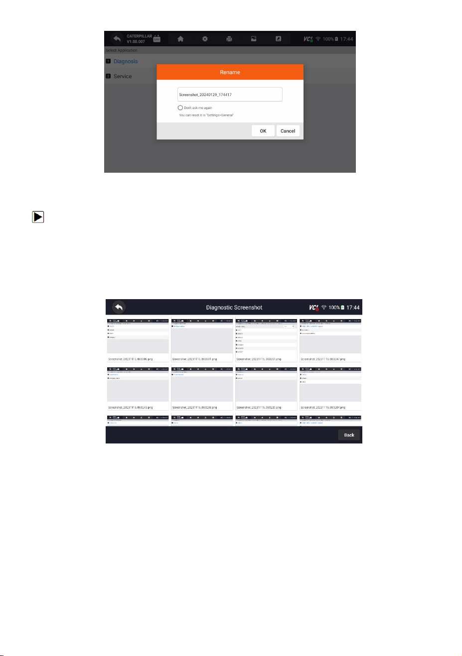
16.1 Image
Image option leads to screens for review of stored screenshots. In case a failure of
HD500 application or the Android system occurs, please just take a screenshot and
send it to our team to help with the troubleshooting.
Typical menu options include:
● Diagnostic Screenshot
● System Screenshot
Figure 16-2 Sample Screenshots Type
16.1.1 How to Save an Image
To take a screenshot:
1. If want to save data of current screen, press at the title bar to take a
screenshot.
Figure 16-3 Sample Screenshot Screen
2. Add a description of the image, and press the OK to save or press cancel button
to give up.
68
HD500 User's Manual V1.3
Figure 16-4 Sample Screenshot Screen
16.1.2 Review Image
To review the screenshots:
1. Press Data Manager from home screen of HD500 diagnostic application.
2. Press Image from Data Manager.
3. Press Diagnostic Screenshot for application menu screenshot or Press System
Screenshot for system menu screenshot, then all available pictures will be
displayed.
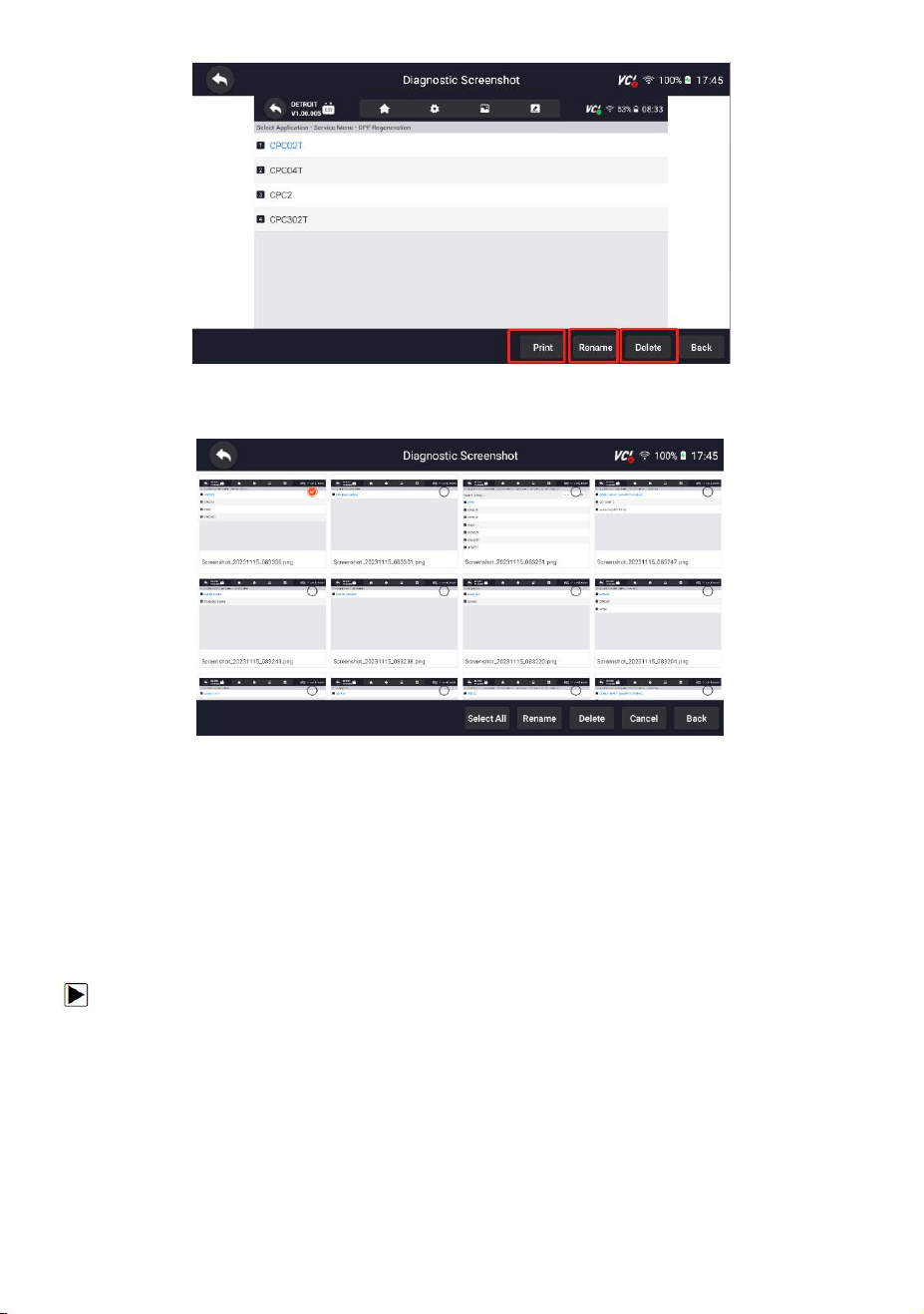
Figure 16-5 Sample Browse Picture Screen
4. Press any available picture for review.
5. To delete a picture, tap button Delete and answer OK to delete. Press Print to
print the pictures and press Rename to change the picture name.
69
HD500 User's Manual V1.3
Figure 16-6 Sample Edit Picture Screen
6. Long press one of the pictures to edit all pictures like Rename or Delete.
Figure 16-7 Sample All Pictures Edit Screen
16.2 PDF Report
PDF option leads to screens for review of the vehicle test reports. You just need to
press the PDF icon on the test screen, add a description and press OK button to
save.
16.2.1 How to Create a PDF Report
To create a PDF report:
1. Press Data Manager from home screen of HD500 diagnostic application.
2. Press Report from Data Manager.
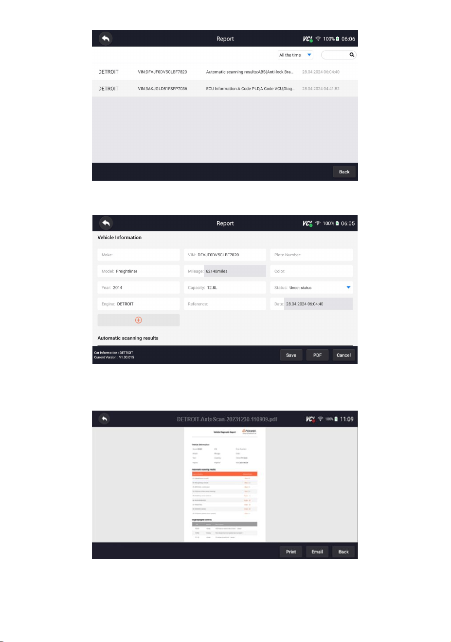
3. Press any reports saved.
70
HD500 User's Manual V1.3
Figure 16-8 Sample of Reports Screen
4. Press Save to save changes. Press PDF to create PDF file.
Figure 16-9 Sample of Report edit Screen
5. If press PDF, the PDF review screen will be displayed. Press Print to print the
report or press Email to share the report.
Figure 16-10 Sample of Report Edit Screen
71
HD500 User's Manual V1.3
16.2.2 Review PDF Report
To review the PDF reports:
1. Press Data Manager from home screen of HD500 diagnostic application.
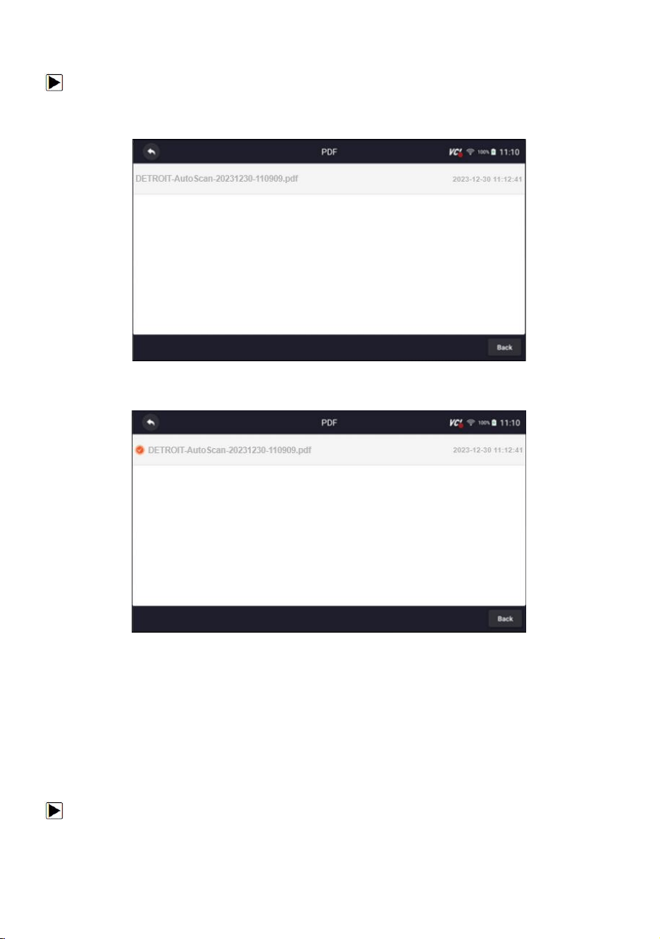
2. Press PDF and all available PDF files will be displayed.
Figure 16-11 Sample Browse PDF Screen
3. Long press the screen to edit all PDF files like Rename or Delete the files.
Figure 16-12 Sample Edit PDF Screen
16.3 Data Playback
The Data Playback option leads to screens for review of recorded live data. Playing
back a recording is just like using the scan tool on a live vehicle. It let you review
live data in text, graph and graph merging formats. Playback speed and direction
(forward or reverse) can also be controlled.
To review recorded live data:
1. Press Data Manager from home screen of HD500 diagnostic application.
2. Press Data Playback and all available records display.
72
HD500 User's Manual V1.3
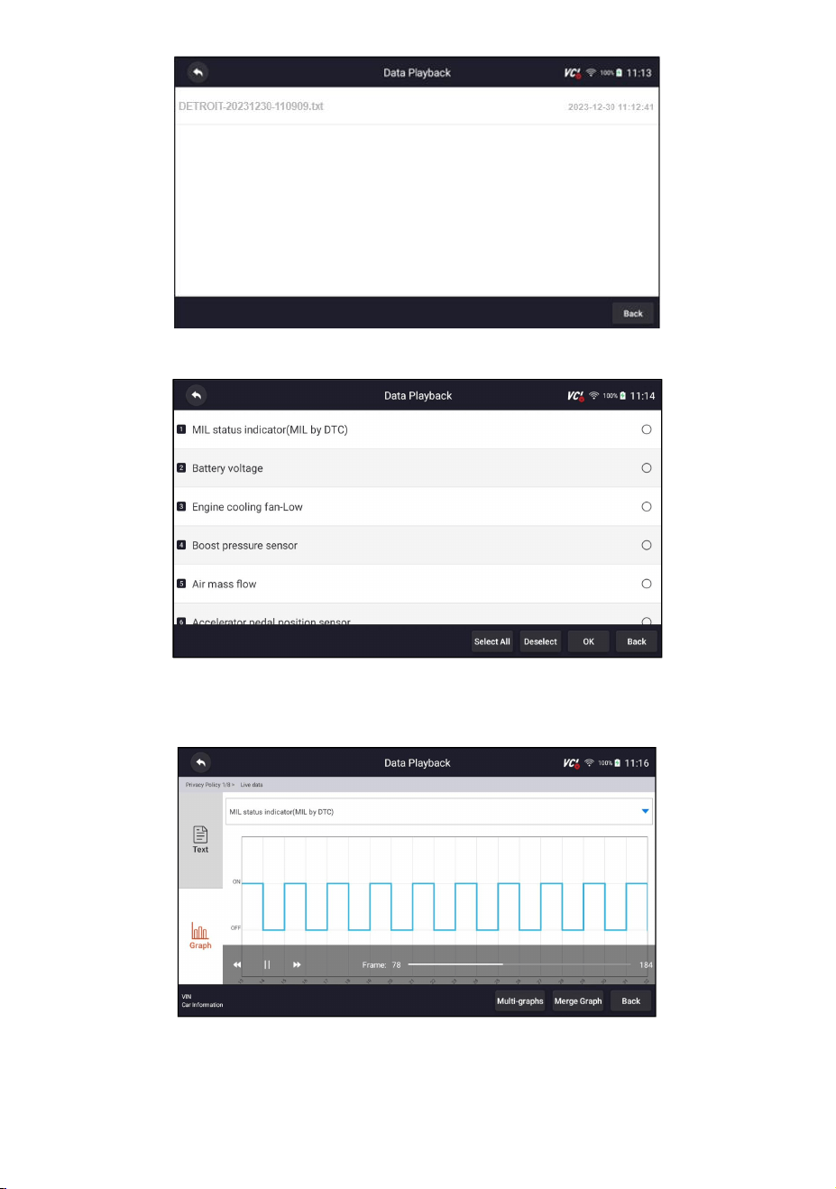
Figure 16-13 Sample Data Playback Records Screen
3. Press any records to view the details.
Figure 16-14 Sample Data Playback Selections Screen
4. To view parameter graphs, press the Graph tab. And to merge the graphs, press
the tab Merge Graph or press the tab Multi Graph to view multiple plots.
Figure 16-15 Sample Graph Screen

73
HD500 User's Manual V1.3
5. To move forward or reverse back of the playing, just drag the progress bar
forward or reverse. Press the button to stop.
6. Long press the record to Rename or Delete the records.
Figure 16-16 Sample Edit Data Playback Screen
17 Settings
This section illustrates how to program the scanner to meet your specific needs.
When Settings application is selected, a menu with available service options
displays. Menu options typically include:
● Unit
● Language
● Font Size
● Module Sorting
● Sort Tiles
● Remote control
● Automatic Update
● System Settings
● General
● Uninstall Vehicle Software
● Clear app data
● Print Settings
● About
17.1 Unit
Selecting Unit opens a dialog box that allows you to choose between Imperial
customary or metric units of measure.
To change the unit setup:
74
HD500 User's Manual V1.3
1. Press Settings from home screen of the HD500 diagnostic application.
2. Press Unit and available unit system display.
3. Select a unit system.
17.2 Language
Select Language opens a screen that allows you to choose system language.
To configure system language:
1. Press Settings from home screen of the HD500 diagnostic application and select
Language. Then all available language options display.
2. Select your preferred language to change.
17.3 Font Size
This option allows you to change the font size of application.
To change font size:
1.
Press Settings from home screen of the HD500 diagnostic application, and then
select Font Size.
2. Select your preferred font size, then press Confirm to change, or press Back to
give up.
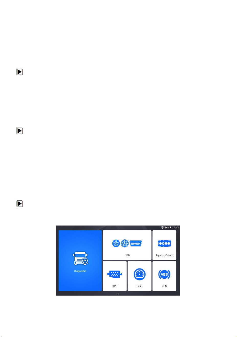
17.4 Module Sorting
This option allows you to modify the display order of other modules except the
diagnostic module in the home screen of HD500 diagnostic application.
To change module sorting:
1. Press Settings from home screen of the HD500 diagnostic application, and then
select Module Sorting.
Figure 17-1 Sample Before the modification,
the Injector cutoff Module is displayed behind the OBD module
75
HD500 User's Manual V1.3
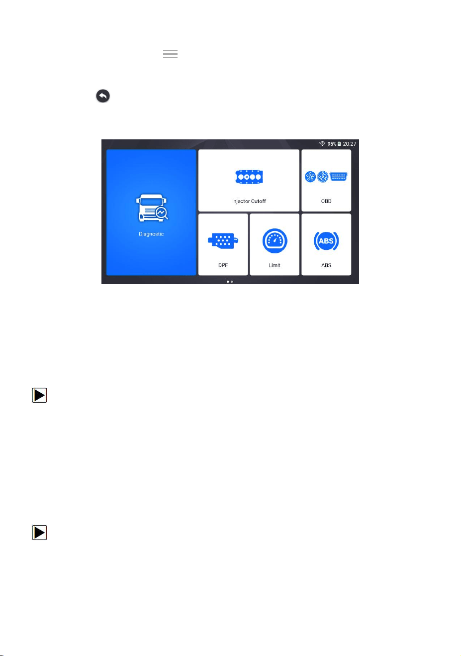
2.Long press the icon on the right side of the module that needs to be
modified for about 2 seconds, and then drag it up and down. The final position of
the module is the same as the display order of the home screen.
3. Click to display whether to apply the current settings interface, click OK to
apply the current changes, click Cancel to discard the current changes.
Figure 17-2 Sample After the modification,
The Injector cutoff module is displayed in front of the OBD module
17.5 Sort Tiles
This option allows you to change the sort for Brand of vehicles. There are two
sorting methods available by alphabet or by frequency of use.
To change sort
1. Press Settings from home screen of the HD500 diagnostic application, and select
Sort Tiles.
2. Select your preferred sort order.
17.6 Remote Control
This option allows you to select a tool of remote control. There are two remote
tools available TeamViewer QuickSupport or AnyDesk.
To change remote control
1. Press Settings from home screen of the HD500 diagnostic application, then select
Remote control.
2. Select your preferred tool.
76
HD500 User's Manual V1.3
17.7 Automatic Update
This option allows you to enable/disable automatic update notice. If it is enabled,
an orange update mark will show on the upper right of the diagnostic software icon
whenever there is a new version available.
17.8 System Settings
This option provides you a direct access to the Android system settings, like sound,
display, system security and etc. Refer to Android documentation for more
information.
17.9 General
This option lets you to turn on/off the prompt when saving a file or login &
registration when started the scanner.
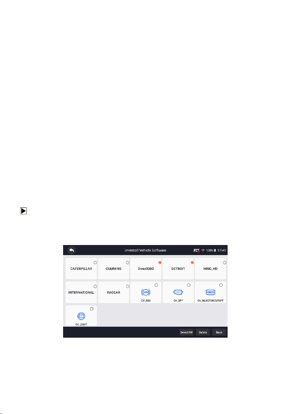
17.10 Uninstall Vehicle Software
This option allows you to uninstall the vehicle software installed in the scanner.
To uninstall a vehicle software:
1. Tap Settings application on home screen of HD500.
2. Tap the Uninstall Vehicle Software option on the option list.
3. Choose the vehicle software you want to delete or choose Select All.
Figure 17-3 Sample Uninstall Vehicle Software Screen
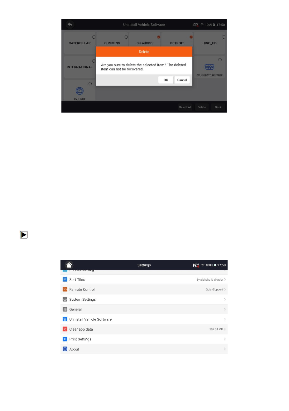
4. Press Cancel to quit or and press OK to uninstall.
77
HD500 User's Manual V1.3
Figure 17-4 Sample Uninstall Vehicle Software Screen
17.11 Clear App Data
Generally, after the application running for a period of time, some cache data will
be generated. As time goes by, the cached data will become larger and larger,
which will affect the operation of the device. This option allow you to clear the
cache data of the app.
17.12 Print Settings
This option allows you to print any data or information anywhere and anytime
either via PC network or Wi-Fi.
To setup the printer connection:
1. Tap the Settings application on home screen of HD500.
2. Tap the Printing Settings option on the option list.
Figure 17-5 Sample Print Settings Screen
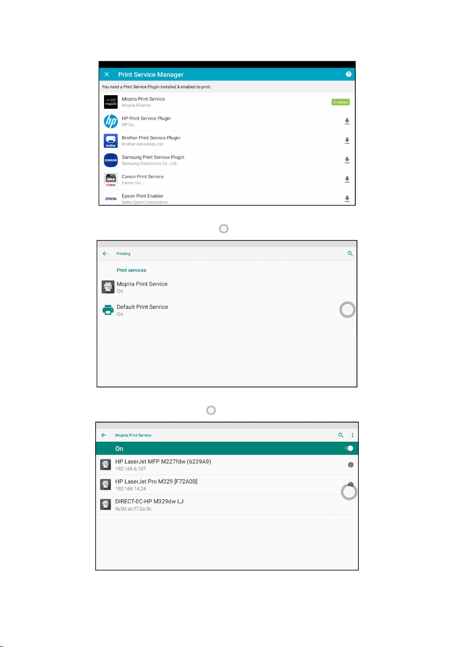
78
HD500 User's Manual V1.3
3. Tap Print Plugin Manager and turn on the Mopria Print Service, then HD500 will
search for available printers automatically.
Figure 17-6 Sample Print Service Manager Screen
4. Select Mopria Print Service. Press for return.
Figure 17-7 Sample Setting of Print Service Manager Screen
5. Choose the right printer. Press for return.
Figure 17-8 Sample of Printer Screen
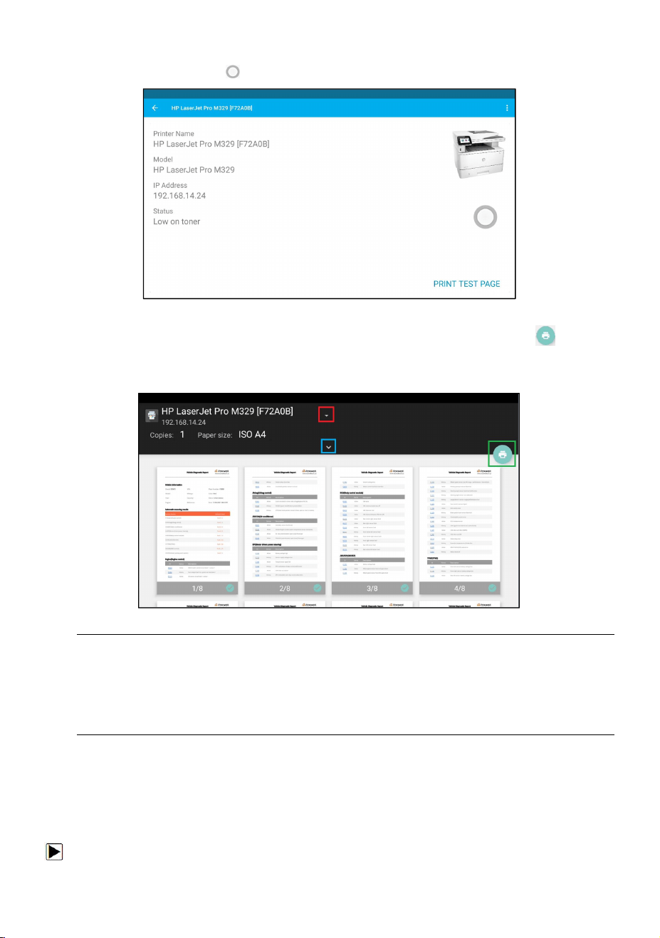
79
HD500 User's Manual V1.3
6. Select a available printer, then press PRINT TEST PAGE button at the
right-bottom. Press for return.
Figure 17-9 Sample of Printer test
7. Choose the file or report you want to print and press the print icon . Click on
the red marked part to select an available printer. Click the blue marked part to
make more settings for the printer, such as paper size, number of copies, etc.
Figure 17-10 Sample of File Printing Screen
NOTE
1. Please make sure the printer and the HD500 in the same Wi-Fi or Network when
printing.
2. If Mopria Print Service driver can’t workable for your printer, please download
the driver to work for your printer on Print Service Manager.
17.13 About
Selecting About option opens a screen that shows information about the HD500,
such as serial number, hardware and software version and etc.
To view information of your scan tool:
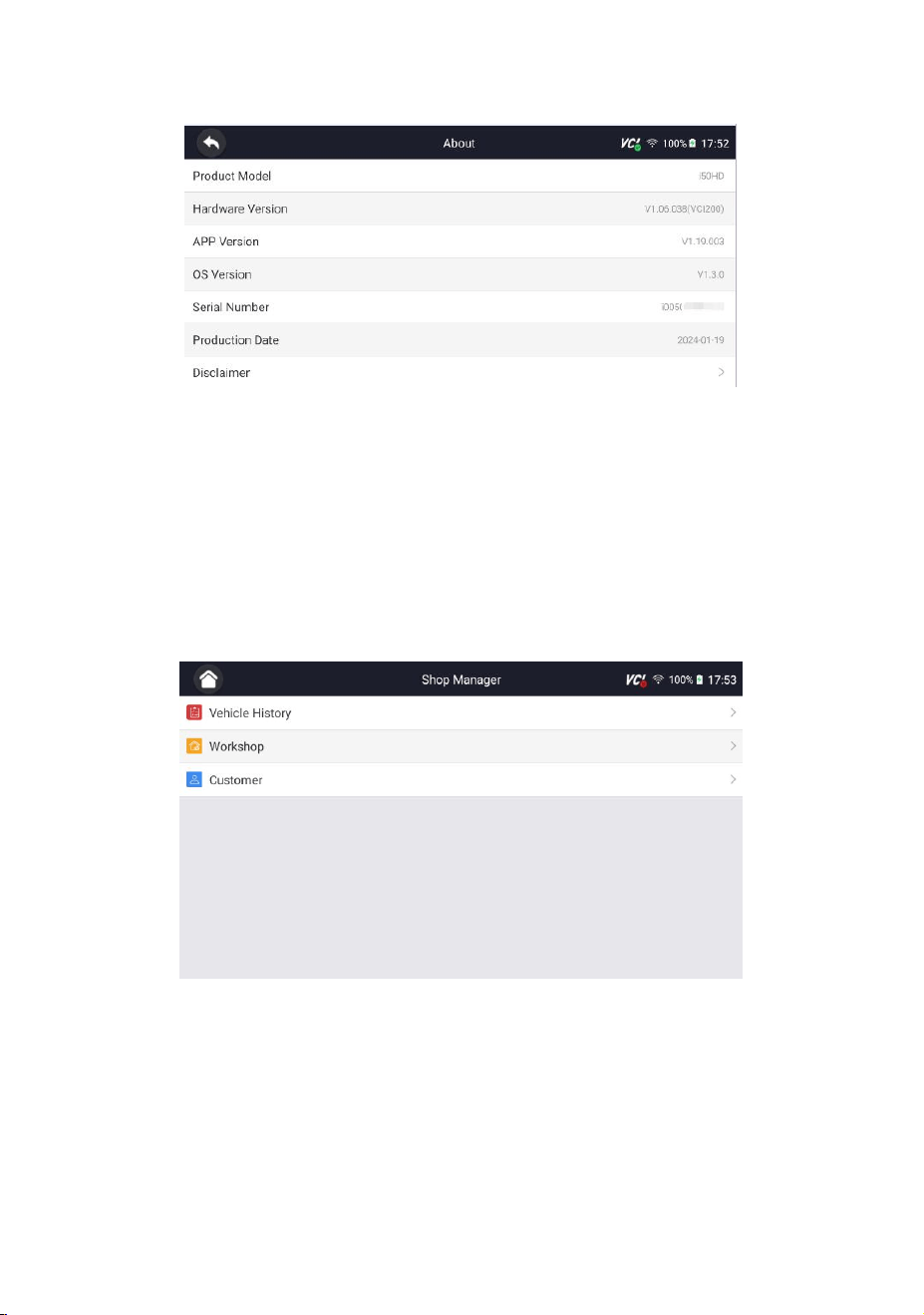
80
HD500 User's Manual V1.3
1. Press About from home screen of the HD500 diagnostic application.
2. A screen with detailed information of the scanner displays.
Figure 17-11 Sample Tool Information Screen
18 Shop Manager
Allows technicians to manage shop floor information and vehicle test records.
Menu options typically include:
● Vehicle History
● Workshop
● Customer
Figure 18-1 Sample Shop Manager Screen
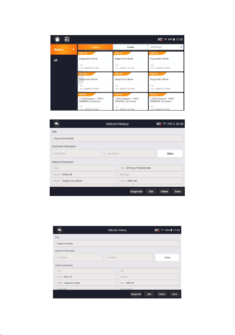
81
HD500 User's Manual V1.3
18.1 Vehicle History
Figure 18-2 Sample Workshop Screen
Figure 18-3 Sample Workshop Screen
18.2 Workshop
Figure 18-4 Sample Workshop Screen
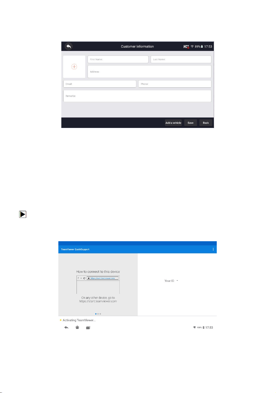
82
HD500 User's Manual V1.3
18.3 Customer
Figure 18-5 Sample Customer Screen
19 Remote Support
Remote Control enables you to get remote support from Foxwell with TeamViewer
when you have issues with Foxwell products.
There are two remote control tools TeamViewer QuickSupport and AnyDesk.
About how to set the tool of default, please refer to 11.6 Remote control.
To use QuickSupport for to remote control:
1. Click the Remote Control icon on the main menu of the HD500 to start
TeamViewer QuickSupport.
Figure 19-1 Sample Quick Support Screen
2.Send your ID to us to let our team to take control your tablet.

