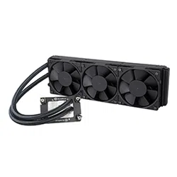
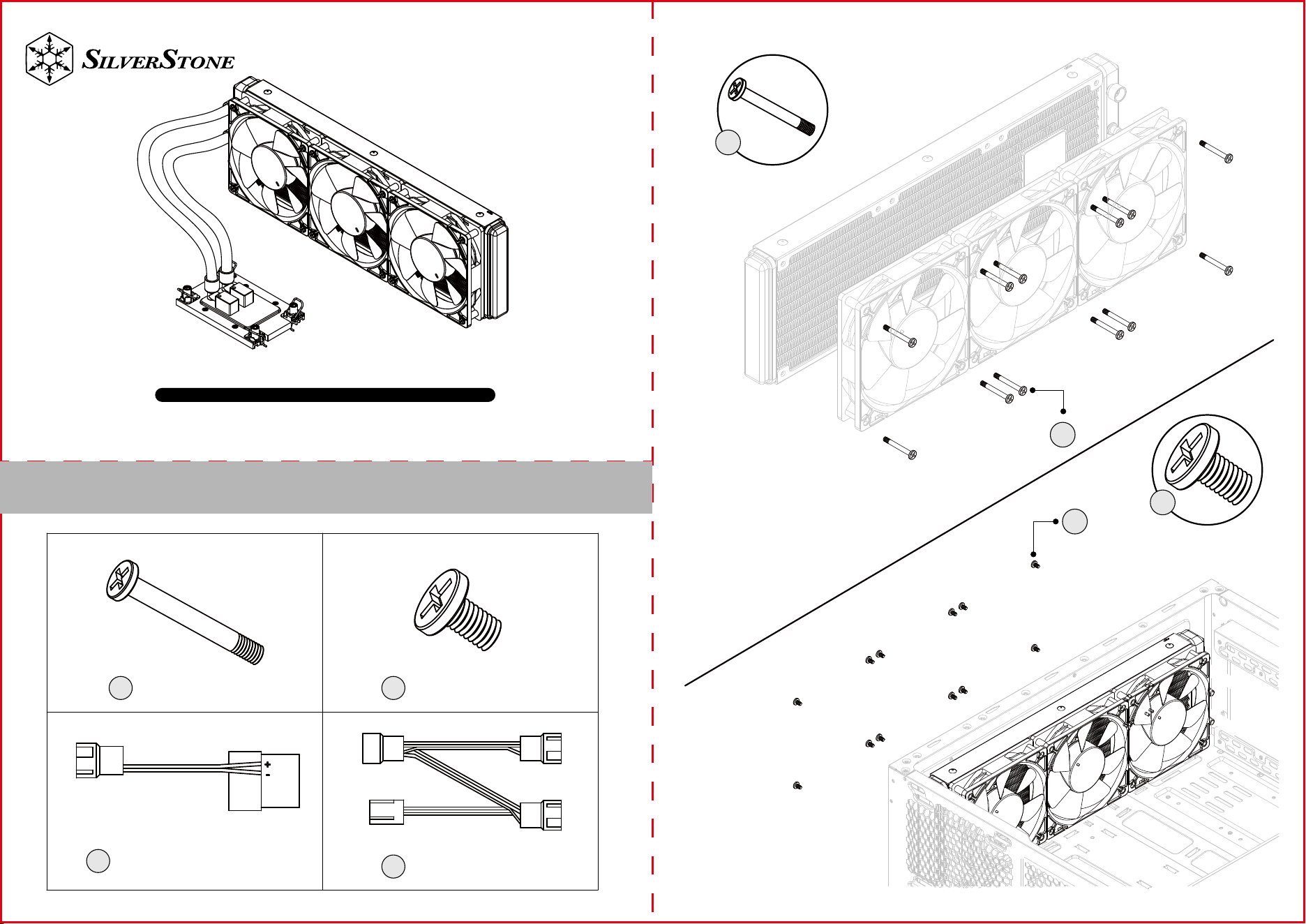
High performance All-In-One liquid cooler
XE360-4677
www.silverstonetek.com
User manual
Contents
BA
Fan Screw x12
C
4pin Peripheral
adapter cable x1
Case Screw x12
D
3 in 1 Fan cable x1
A
A
B
B
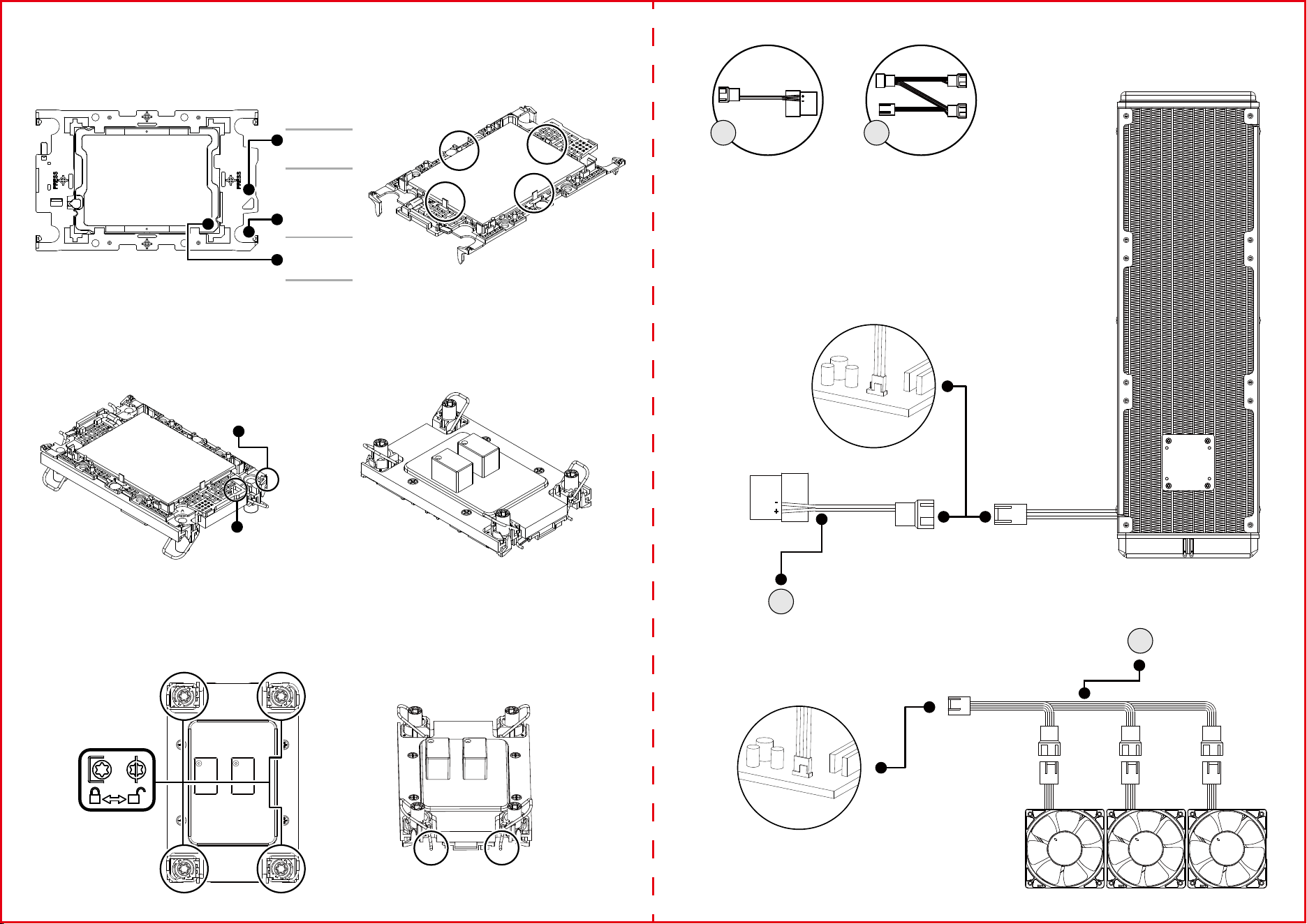
PSU
AIO_PUMP
CPU_FAN
C D
C
D
1.Please wear ESD gloves to protect the processor and CPU socket before installation process
2.Install the processor first with the plastic carrier. Align the golden color triangle mark with the hollow triangle mark on the carrier, then align the
key on the processor IHS cover and side, push the processor and confirm the 4 clips securely locked (Figure 1 &2)
Note: the carrier latches must be fully engaged with the keying slots on the edges of the processor and the processor must be securely seated
on the carrier after insertion.
3.Remove the heatsink from its packaging and remove the protection cover of Thermal Interface Material (TIM). The required amount of TIM has
been pre-applied on the bottom of the heatsink. Inspect the pre-applied TIM for any damage before use.
4.Identify processor Pin 1 and onboard socket Pin 1 to decide the heatsink installation direction; for certain motherboards, the Pin 1 location will
be different with CPU1 and CPU2. (Figure 3 & 4)
Note: The complete assembly of processor, carrier, and heat sink is called Processor Heat Sink Loading Module (PHLM) or Processor Heat Sink
Module (PHM).
5.Before assembling PHM on bolster plate, follow the sticker instructions to ensure all wires are in unlocked position. Install PHM on bolster
plate, and move all wires to locked position, then use Torx T30 screwdriver to tighten each nut of 8 LBF-IN (0.904 N-M) (Figure 5 & 6)
Hollow Triangle
Marker on the
Carrier
Pin-1 Golden
Triangle Marker
both on CPU
Top and Bottom
Substrate
Solid Triangle
Marker on the
Carrier
Carrier Latches and keying
1
2
3
Figure 1 Figure 2
Figure 3 Figure 4
Figure 5 Figure 6
Pin 1 solid triangle
mark on carrier top
Pin 1 hollow triangle
mark on carrier
bottom side