STRIDER GOLD S SERIES
High efficiency with 80 PLUS Gold certification
100% modular cables
24/7 continuous power output with 40℃ operating temperature
1600W peak power
Strict ±3% voltage regulation and low ripple & noise
Silent running 135mm fan with 18dBA minimum
Eight PCI-E 8/2pin connectors support
Compact design with a depth of 180mm for easy integration
ST1500-GS
World’s smallest, full-modular ATX power supplies

The following manual and guides were carefully prepared by the SilverStone engineering team to
help you maximize the potential of your SilverStone product. Please keep this manual for future
reference when upgrading or performing maintenance on your system. A copy of this manual can also
be downloaded from our website at:
Installation and system optimization guide:
Specification
AC Input
DC Output
Protection
Timing
Environment
Safety
Electromagnetic compatibility (EMC)
MTBF
Mechanical
P.1
P.1
P.2
P.4
P.5
P.6
P.6
P.6
P.7
P.7
STRIDER GOLD S SERIES
ST1500-GS
World’s smallest, full-modular ATX power supplies
1
SilverStone Strider Gold S
ST1500-GS
ATX12V / EPS 12V Switching Power Supply
With Active PFC
80 PLUS Gold
PS/2
To meet the requirements of current and future desktop computers, SilverStone created the Strider Gold S
series power supplies. The Strider Gold S models are all new designs engineered to be the smallest, full-modular ATX
power supplies at any wattage levels.
The Strider Gold S series includes wattage range from 550W to 1500W for a great variety of applications.
With short depth designs, all models in the series are among the world’s smallest full-modular ATX PSUs.
In addition to 80 PLUS Gold level efficiency, the Strider Gold S PSUs are built to meet very high standards in
electrical performance with ±3% voltage regulation, ±3% ripple & noise, and high amperage single +12V rail.
Other notable features included are 24/7 40℃ continuous output capability, low-noise fan, and multiple sets of
PCI-E cables. For users looking for a power supply with faultless combination of compact size, performance,
efficiency, and quality, the Strider Gold S Series is the only choice.
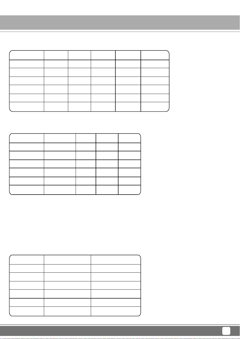
1.1 AC input requirements
The input voltage, current, and frequency requirements for continuous operation are stated below.
1. AC INPUT
The power supply must meet inrush requirements for any rated AC voltage, during turn on at any phase of AC voltage,
during a single cycle AC dropout condition, during repetitive ON/OFF cycling of AC, and over the specified
temperature range (Top). The peak inrush current shall be lessthan the ratings of its critical components
(including input fuse, bulk rectifiers, and surge limiting device).
Parameter
Vin( Full range )
Vin Frequency
Iin
Min.
90
47
Nom.
100---240
60-----50
18-------9
Max.
264
63
Unit
VACrms
Hz
Arms
Table 1 AC Input Line Requirements
Power factor correction (PF)>0.90 at full load.
World’s smallest, full-modular ATX power supplies
2
2.1 DC voltage regulation
2.2 Load ranges
2.3 Output Ripple
2.3.1 Ripple regulation
1. Maximum combined load on +3.3V and +5V outputs shall not exceed 150W.
2. Maximum combined load on +12V outputs shall not exceed 120A(1440W).
3. Maximum continuous total DC output power should not exceed 1500W.
4. Peak total DC output power should not exceed 1600W.
5. Peak power and current loading shall be supported for 12 second.
2. DC OUTPUT
Parameter
+3.3V
+5V
+12V1
+12V2
-12V
+5VSB
Range
+/-3%
+/-3%
+/-3%
+/-3%
+/-10%
+/-5%
Min
+3.20
+4.85
+11.64
+11.64
-13.20
+4.75
Nom.
+3.30
+5.00
+12.00
+12.00
-12.00
+5.00
Max
+3.40
+5.15
+12.36
+12.36
-10.80
+5.25
Unit
Volts
Volts
Volts
Volts
Volts
Volts
Parameter
+3.3V
+5V
+12V1
+12V2
-12V
+5VSB
Min(optional)
0.2
0.2
0.2
0.2
0
0
Nom.
-
-
-
-
-
-
Max
25
25
70
70
0.3
3.5
Unit
Amps
Amps
Amps
Amps
Amps
Amps
Parameter
+3.3V
+5V
+12V1
+12V2
-12V
+5VSB
Ripple&Noise
50
50
120
120
120
50
Unit
mVp-p
mVp-p
mVp-p
mVp-p
mVp-p
mVp-p
STRIDER GOLD S SERIES
ST1500-GS
World’s smallest, full-modular ATX power supplies
3
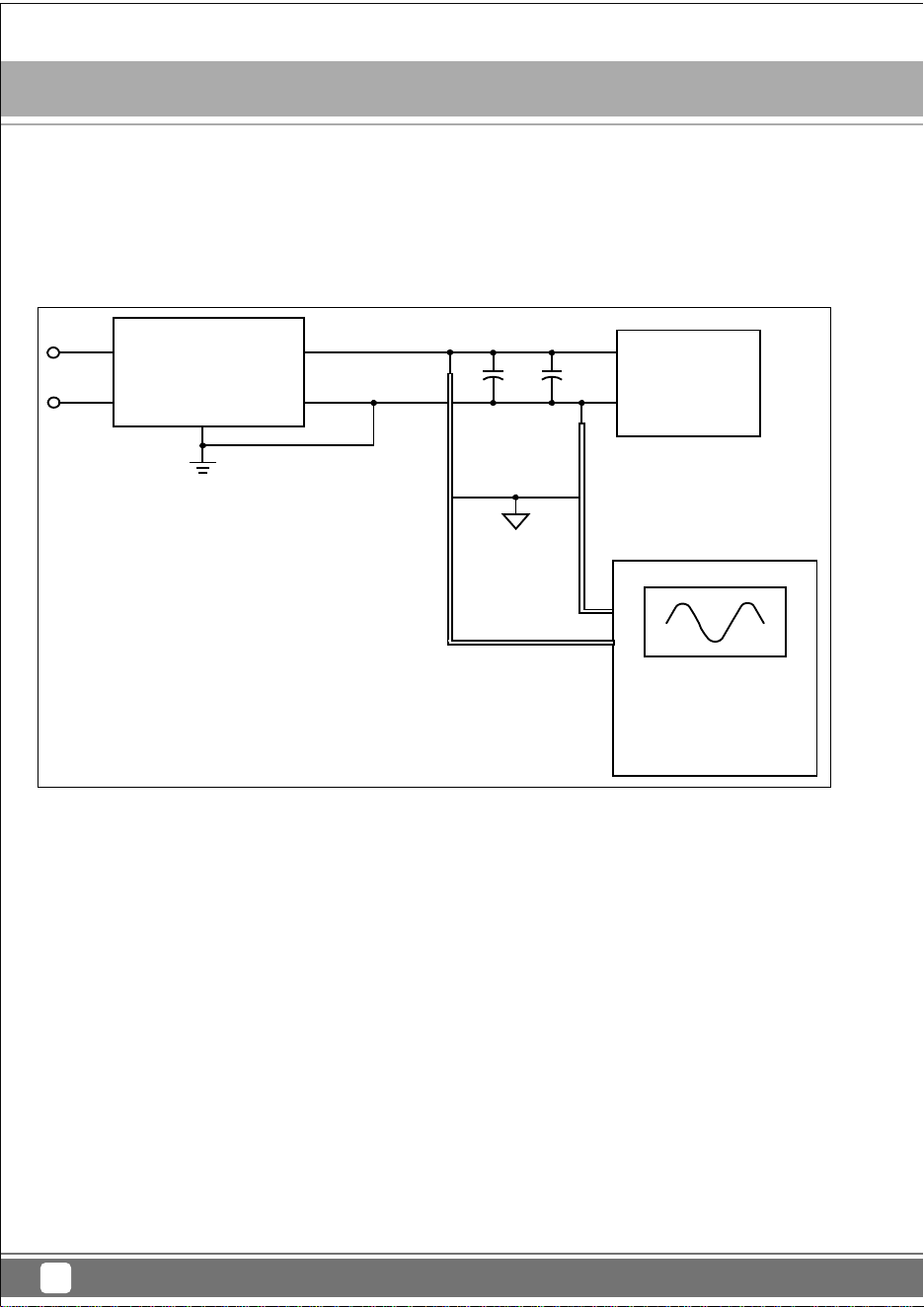
2.3.2 Definition
The ripple voltage of the outputs shall be measured at the pins of the output connector when terminated in the
load impedance specified in figure 1. Ripple and noise are measured at the connectors with a 0.1uF ceramic
capacitor and a 10uF electrolytic capacitor to simulate system loading. Ripple shall be measured under any
condition of line voltage, output load, line frequency, operation temperature.
2.3.3 Ripple voltage test circuit
2.4 Overshoot
Any overshoot at turn on or turn off shall be less 10% of the norminal voltage value, all outputs shall be within the
regulation limit of section 2.0 before issuing the power good signal of section 4.0.
2.5 Efficiency
Power supply efficiency 20% Loading / 87%,50% Loading /90%,100% Loading /87% at normal AC main voltage
(AC input 115V or 230V).
2.6 Remote ON/OFF control
When the logic level "PS-ON" is low, the DC outputs are to be enabled.
When the logic level is high or open collector, the DC outputs are to be disabled.
Figure 1. Ripple voltage test circuit
AC Hot
AC Neutral
Power Supply
V out
V return
10uF 0.1uF
Load
Scope
AC Ground
STRIDER GOLD S SERIES
ST1500-GS
World’s smallest, full-modular ATX power supplies
4
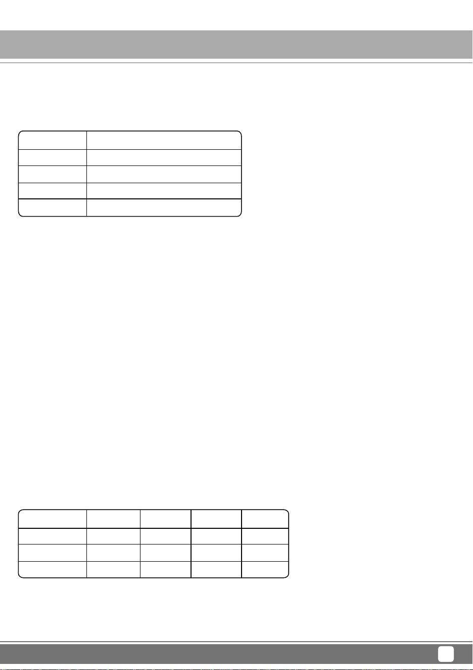
3.1 Over current protection
The power supply shall have current limit to prevent the +3.3V,+5V,and +12V outputs from exceeding the
values shown in the following Table.If the current limits are exceeded the power supply shall shutdown and
latch off.
3.0 PROTECTION
Voltage
+3.3V
+5V
+12V1
+12V2
Over Current Limit (Iout limit)
30A minimum; 48A maximum
30A minimum; 48A maximum
75A minimum; 100A maximum
75A minimum; 100A maximum
Voltage
+3.3V
+5V
+12V
Minimum
3.90
5.70
13.3
Nominal
4.20
6.30
15.0
Maximum
4.50
7.00
16.5
Unit
Volts
Volts
Volts
3.2 Over Temperature Protection
The power supply will be protected against over temperature conditions caused by loss of fan coolng or
excessive ambient temperature. In an OTP condition the PSU will shutdown. When the power supply temperature
drops to within specifide limits, the power supply shall restore power automatically. The OTP circuit must have
built in hysteresis such that the power supply will not oscillate on and off due to temperature recovering condition.
3.3 Over-power protection
The power supply will be shutdown and latch off when output power within 105~150% of rated DC output.
Note: Assurance machine can work at low voltage,full load won't damage machine.
3.4 Under voltage protection
In an under voltage fault occurs, the supply will latch all DC outputs into a shutdown state when +12V,
+5V & +3.3V outputs under 85% of it's maximum value.
3.5 Over voltage protection
The over voltage sense circuitry and reference shall reside in packages that are separate and distinct
from the regulator control circuity and reference.No single point fault shall be able to cause a sustained
over voltage condition on any or all outputs.The supply shall provide latch-mode over voltage protection
as defined in Table.
STRIDER GOLD S SERIES
ST1500-GS
World’s smallest, full-modular ATX power supplies
5
3.6 Short circuit
An output short circuit is defined as any output impedance of less than 0.1 ohms.The power supply shall shut
down and latch off for shorting the +3.3 VDC,+5 VDC,or+12 VDC rails to return or any other rail. Shorts between
main output rails and +5VSB shall not cause any damage to the power supply. The power supply shall either
shut down and latch off or fold back for shorting the negative rails.+5VSB must be capable of being shorted
indefinitely,but when the short is removed, the power supply shall recover automatically or by cycling PS_ON#.
The power supply shall be capable of withstanding a continuous short-circuit to the output without damage or
overstress to the unit.
3.7 No load operation
No damage or hazardous condition should occur with all the DC output connectors disconnected from the load.
The power supply may latch into the shutdown state.
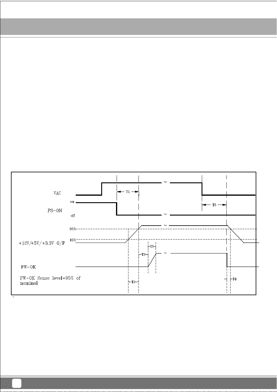
4.1 Signal timing drawing
Figure 2. is a reference for signal timing for main power connector signals and rails.
4. TIMING
4.2 Hold up time
When the power loss its input power, it shall maintain 17ms in regulation limit at normal input voltage.
( Tested at 75% of maximum load and 100-240VAC input ).
1)T3: Power good signal turn on delay time (100ms~500ms)
(2)T4: Power good signal turn off delay time (1ms min)
(3)T2: Rise time (0.1~20ms)
(4)T6: Hold up time (17ms min, Tested at 75% Loading)
Figure 2. PS-OK Timing Sequence
STRIDER GOLD S SERIES
ST1500-GS
World’s smallest, full-modular ATX power supplies
6
5.1 Operation
5. ENVIRONMENT
6.1 Underwriters Laboratory (UL) recognition.
6.2 The power supply must bear the German Bauart Mark from TUV.
The power supply designed to meet UL 1950.
6. SAFETY
7.1 IEC 61000-4-2 ESD LEVEL X20KV4.
7.2 IEC 61000-4-3 radiated electrical field requirement.
7.3 IEC 61000-4-4 BURST.
7.4 IEC 61000-4-5 surge Voltages.
7. ELECTROMAGNETIC COMPATIBILITY (EMC)
Temperature
Relative Humidity
0 to
40℃
10 to 90%, non-condensing
5.2 Shipping and Storage
Temperature
Relative Humidity
-10 to
50℃
5 to 95%, non-condensing
5.3 Altitude
Operating
Storage
10,000FT max
50,000FT max
STRIDER GOLD S SERIES
ST1500-GS

World’s smallest, full-modular ATX power supplies
7
7.5 EN61000-3-2 harmonic current emissions.
If applicable to sales in Japan or Europe, the power supply shall meet the requirements of EN 61000-3-2 class
D and the guidelines for the suppression of harmonics in appliances and general use equipment class D for
harmonic line current content at full-rated power.
7.6 EN55024 class B radio interference (CISPR 22)
7.7 FCC part 15, subpart J class B 115VAC operation.
8.1 MTBF (mean time between failures) calculation
The demonstrated MTBF shall be 100,000 hours of continuous operation at
25℃
,full load, and nominal line.
The MTBF of the power supply be calculated in accordance with MIL-HDBK-217F. The DC FAN is not included.
8. MTBF
9.1 Physical Dimension
150 mm (W) × 86 mm (H) × 180mm (D)
9. MECHANICAL
STRIDER GOLD S SERIES
ST1500-GS


G11221380