1
Ultra-thin · Full graphic
Autonomous system · Environmentally friendly
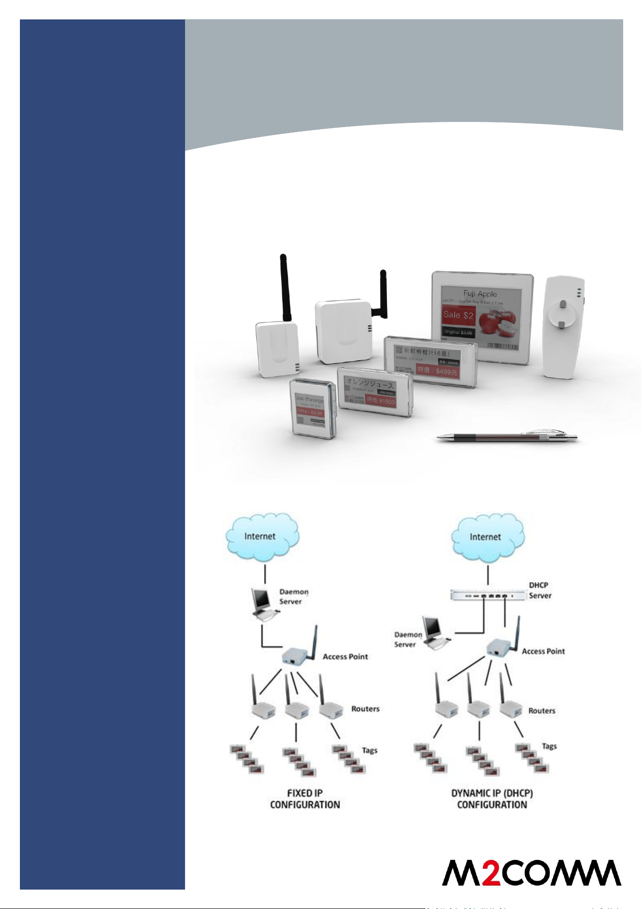
ELSA-E
Electronic Shelf Labeling System
RELIABLE CELLULAR-
LIKE TECHNOLOGY
Unique tree network
for optimal coverage
without interference
from existing Wi-Fi
networks
EASY PLUG-AND-PLAY
SYSTEM
Self-networking
system enables easy
infrastructure setup
EXCEPTIONAL
READABILITY
High resolution e-paper
display for 180° viewing
LONG BATTERY LIFE &
FAST UPDATES
Unique wireless
protocol tuned to
optimize the power
consumption and
network efficiency
ANTI-JAMMIMG
FROM Wi-Fi
13,500 graphic tags are
fully updated per hour
INTELLIGENT SYSTEM
Acknowledges updates;
battery level and signal
strength notifications
2
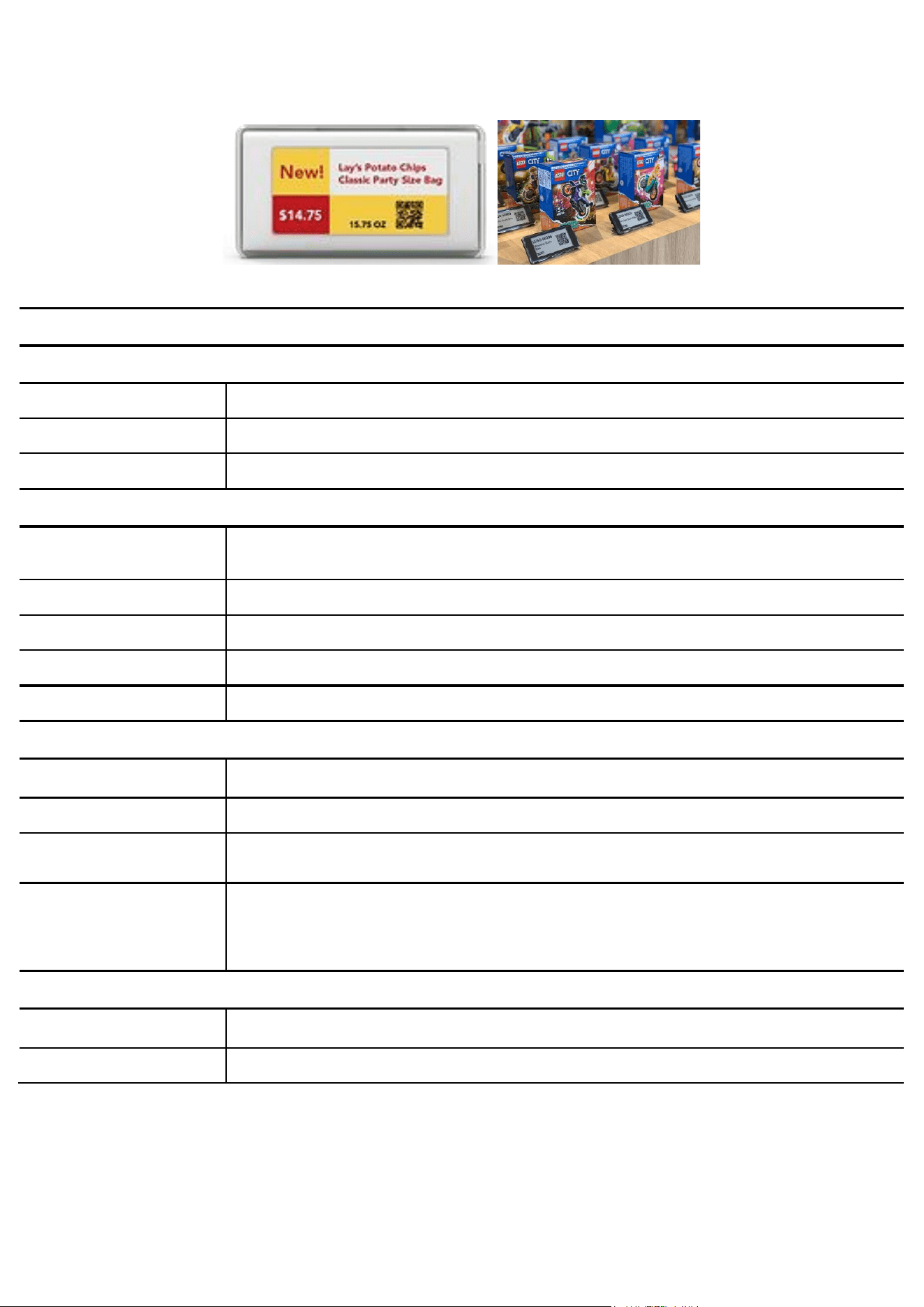
Technical Specification
MODEL NAME: EF27-S2
INFRASTRUCTURE
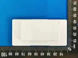
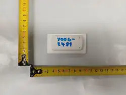
SIZE (W x H x T) mm
83 x 42 x 9.5
WEIGHT, g
39
ANTENNA
EMBEDDED
NETWORK
INTERFACE
WIRELESS
FREQUENCY
SUB-GHz ISM
OPERATION MODE
SELF-NETWORKING (AUTOMATIC CONNECTION BUILT-UP AND RECOVERY)
ENCRYPTION
AES 128-bit
TRANSMISSION RANGE
100 METERS (LINE OF SIGHT)
OPERATING CONDITIONS
OPERATING
TEMP/HUMIDITY
0 ~ 40°C / 35 ~ 55% (non-condensed)
STORAGE TEMP/HUMIDITY
0 ~ 40°C / 35 ~ 80% (non-condensed)
POWER
2 x CR2450
APPLICATIONS
Retail, Smart Display
Display
RESOLUTION
296 x 152
DPI
125 pixel
3
Device Setup:
Access Point Setting
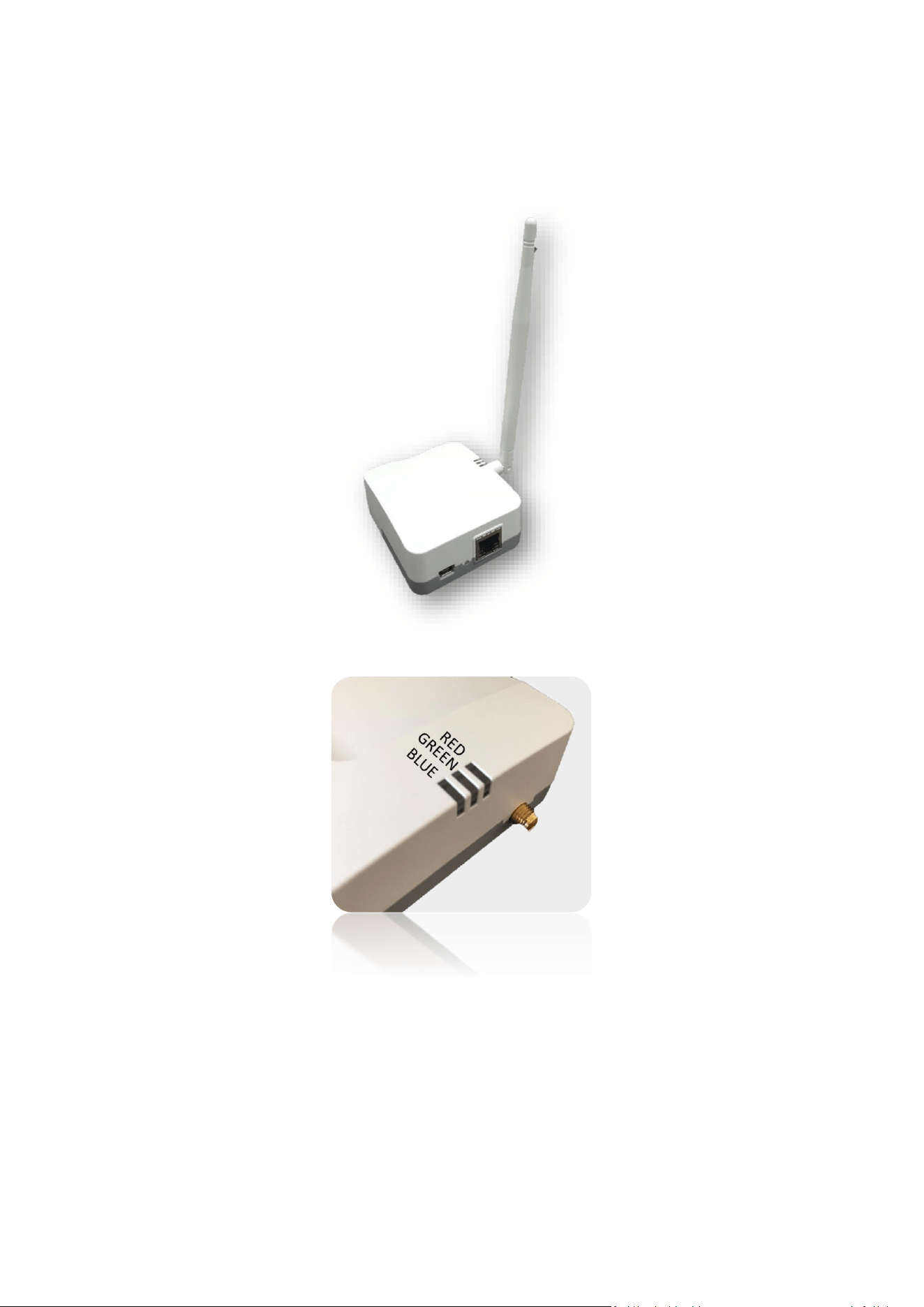
The Access Point has a wired connection to the base station (computer) and communicates wirelessly with the Router(s)
via the M2COMM proprietary protocol.
Please refer to below procedure to setup your Access Point.
Status Indicators and Assembly:
LED status functions:
Red –Power-on self-test error
Green –Power on indicator
Blue –Network connection, shall flash slowly during boot-up and stay on while connection is built up successfully.
4
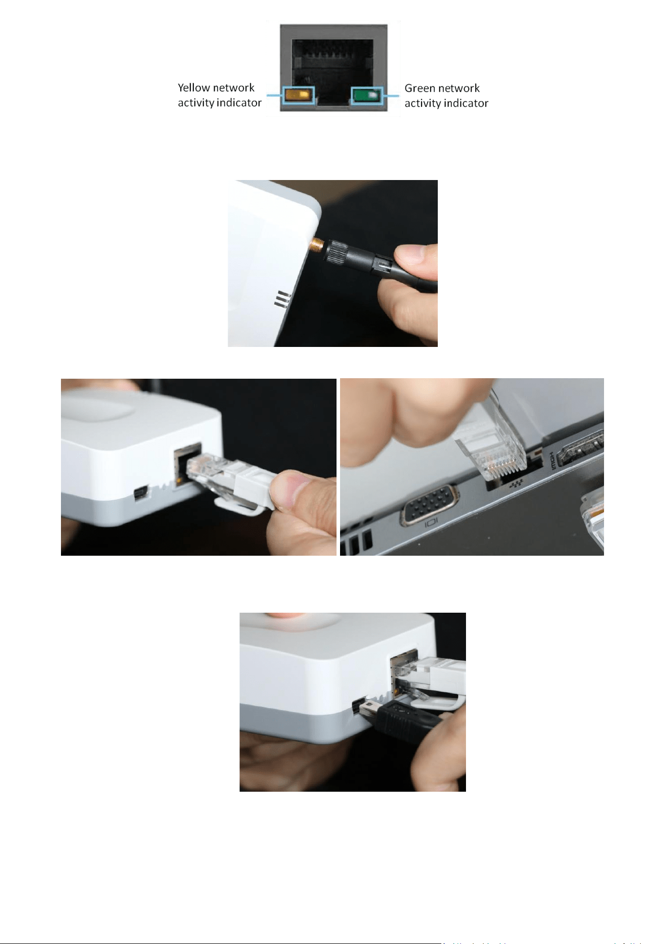
Access Point - Network Port:
GREEN network activity indicator—turns on when a cable connects the port to another Gigabit Ethernet port
YELLOW activity indicator—Flashes to indicate network activity over that port
Attach included Antenna
Plug one end of the supplied Cat 5E cable into the Access Point, the other end should be plugged into your computer.
Connect the supplied AC power adaptor as shown.
Use only the adapter that came with your Access Point
5
Router Setting
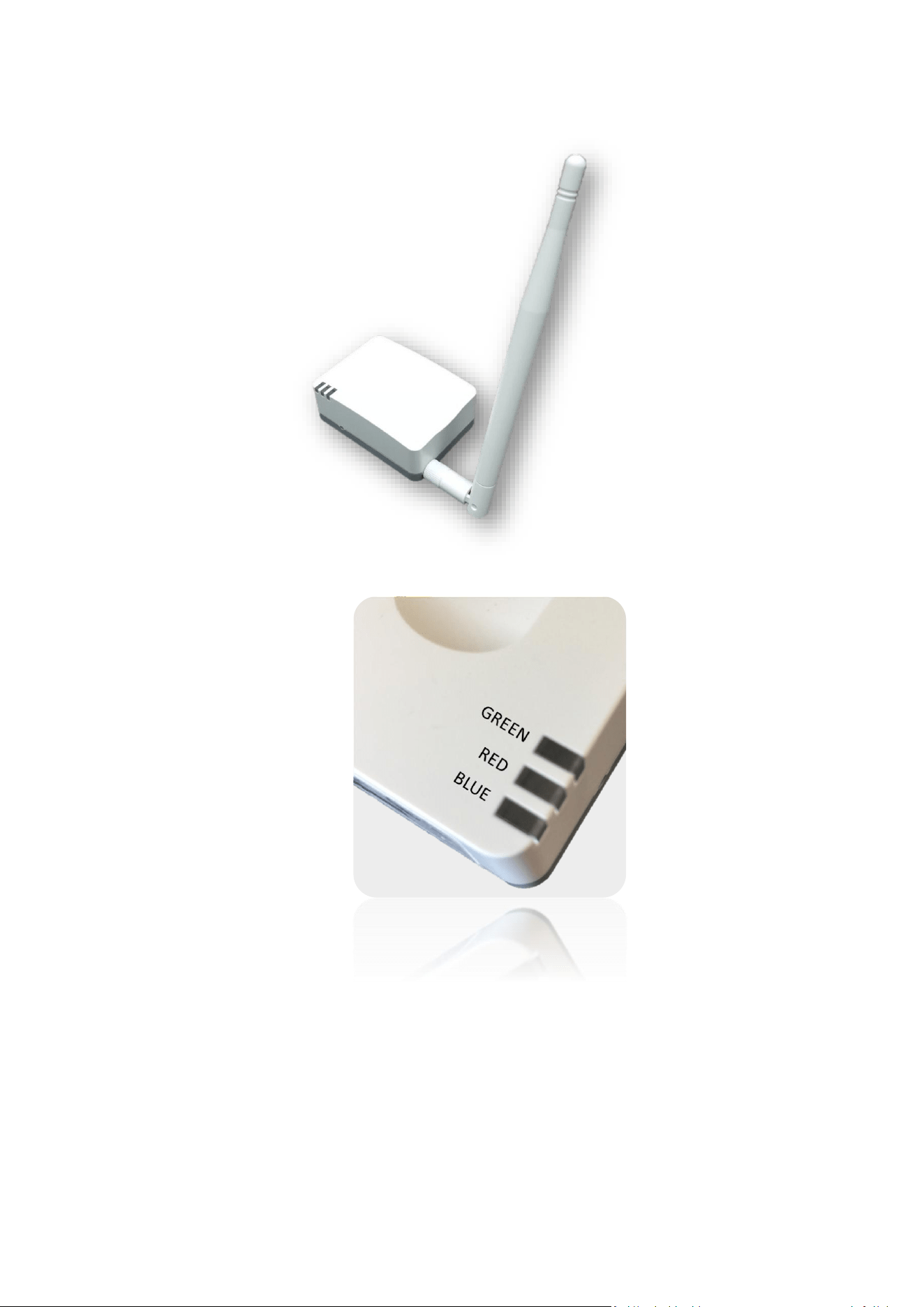
The Router(s) operate wirelessly, via the M2COMM proprietary protocol, with the Access Point and aisle light.
Please refer to below procedure to setup the Router.
Status Indicators and Assembly:
LED status functions:
Red –Power-on self-test error
Green –Power on indicator
Blue –Network connection, shall flash slowly during boot-up and stay on while connection is built up successfully.
6
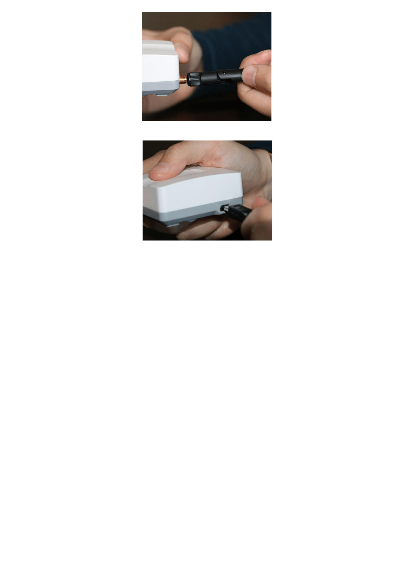
Attach included Antenna
Connect the included AC power adaptor as shown.
Use only the adapter that came with your Router
7
ELSA-E Demo System IP setting:
The ELSA-E demo system is designed to use either a static IP address for a single Access Point or a dynamic IP address
when multiple Access Points are installed.
IP Address Configuration (Static IP):
Ensure that your Access Point is connected to your computer.
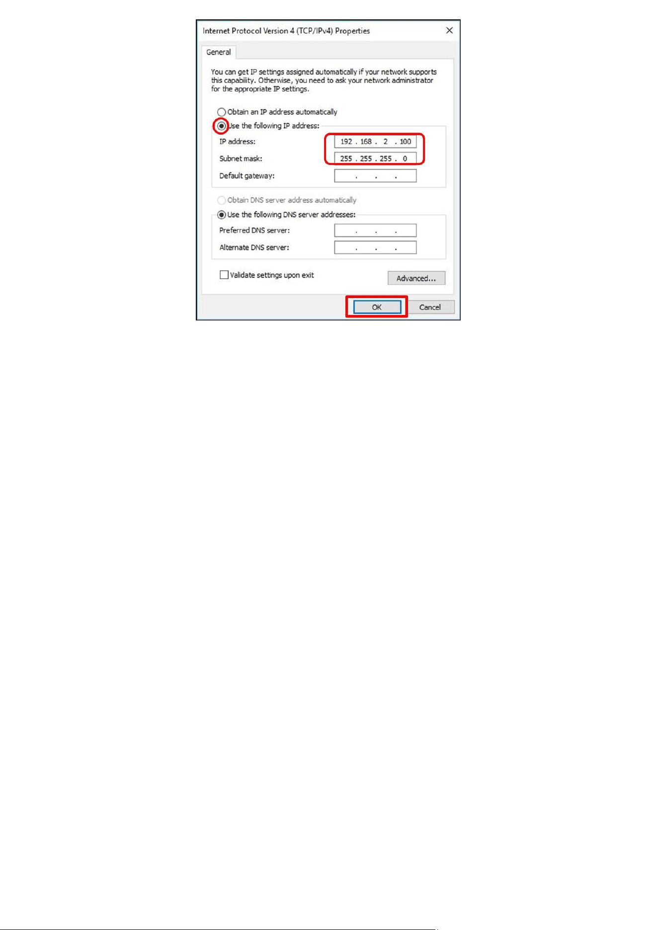
The Access Point comes pre-configured with a default IP Address (192.168.2.1). It’s necessary to modify the IP Address
of the Ethernet port on your computer that is cabled to the M2COMM Access Point so that they can communicate with
one another.
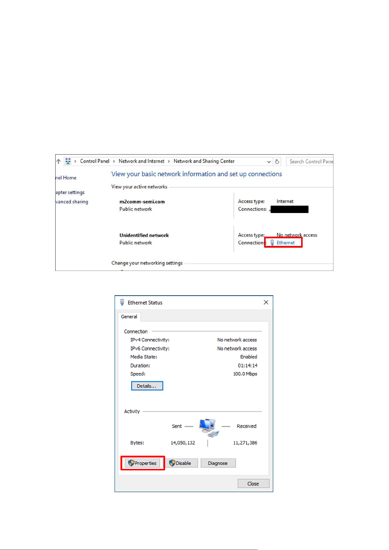
Using your computer mouse, click on Ethernet
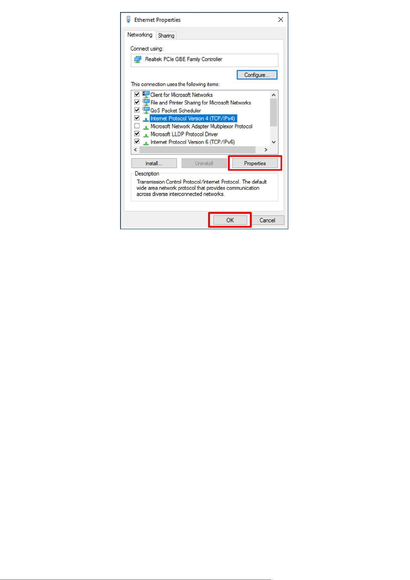
Select Properties
8
Select Internet Protocol Version 4 (TCP/IPv4), and select Properties
9
Check Use the following IP address and enter information shown above. Select OK to apply new settings
IP Address Configuration (Dynamic IP):
For installations that contain multiple Access Points an external TCP/IP Ethernet hub is required. And please contact
M2COMM for further details.
10
M2COMM ELSA-E Demo Installation:
Software Installation:
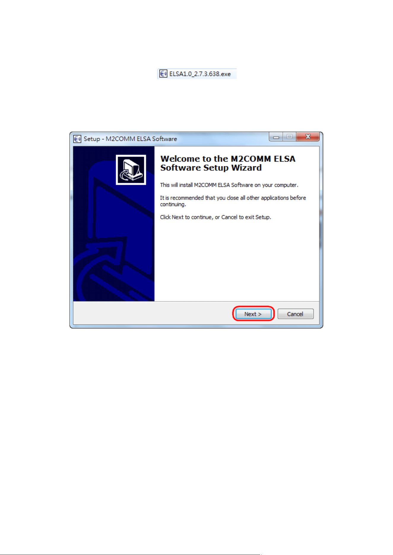
Put below two executable files into the same folder on your computer. And double-click the “ELSA1.0_2.x.x.xxxx.exe”
file to begin the installation.
You may be asked for permission to allow the program to make changes to your computer; you must agree to this to
enable installation to start.
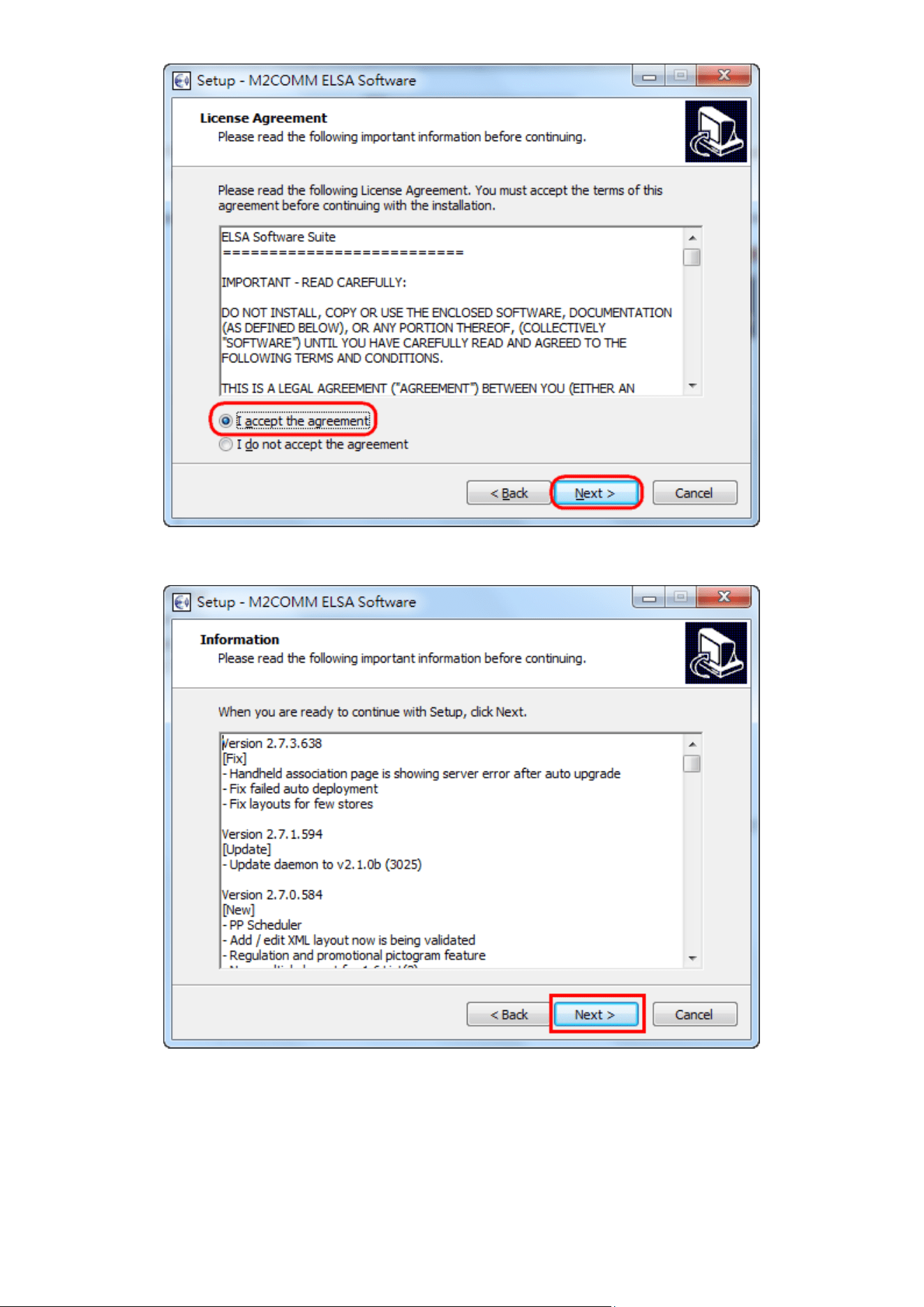
Follow the on-screen instructions to finish the installation process.
Click Next> to continue
11
Select Accept, and Click Next> to continue
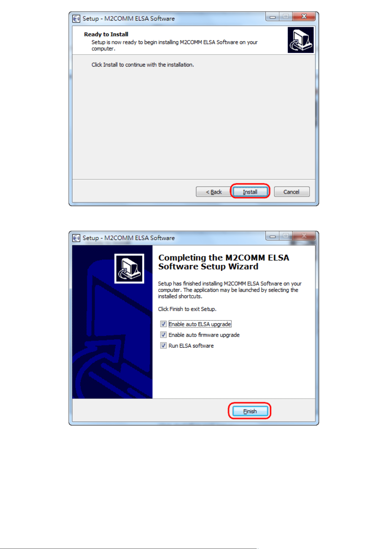
Click Next to continue
12
Click Install to start
Click Finish to complete the installation
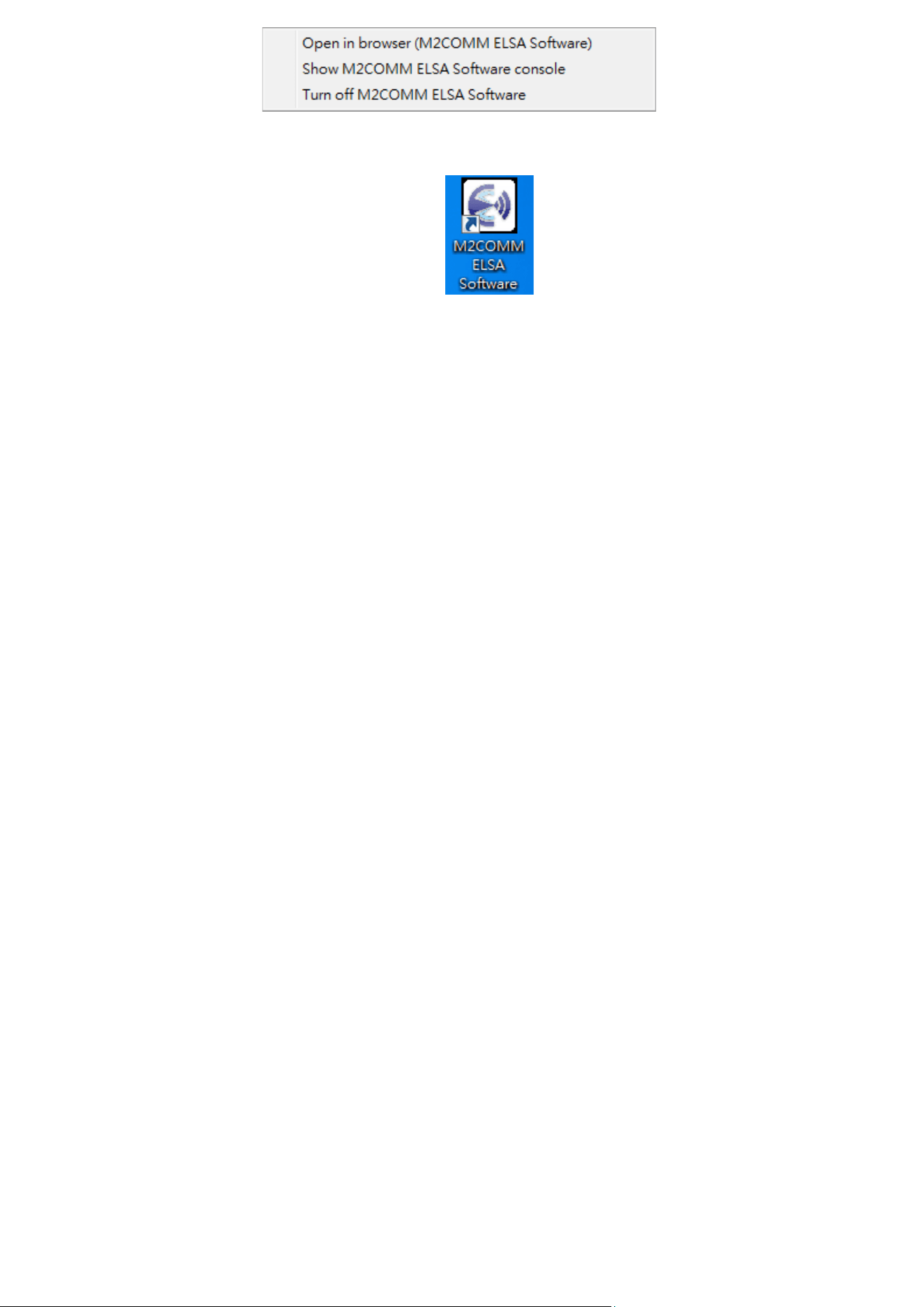
The ELSA-E Demo system has now been installed and executed on your computer. The icon will be hidden inside the
toolbar, and you should now be able to locate this icon on your computer screen, by right click.
13
.
And you can also launch the ELSA software by double click the icon on desktop.

14
Setting Up the ELSA-E 2.7’’ ESL
Ensure that the Access Point is connected to your computer that the Router(s) and 2.7’’ ESL are installed throughout
your premises and are powered on.
• Install the AP
Input “sa” for user name and “passw0rd” for password, to access the ELSA web.
Press “Start” to initial the ELSA system installation process.
15
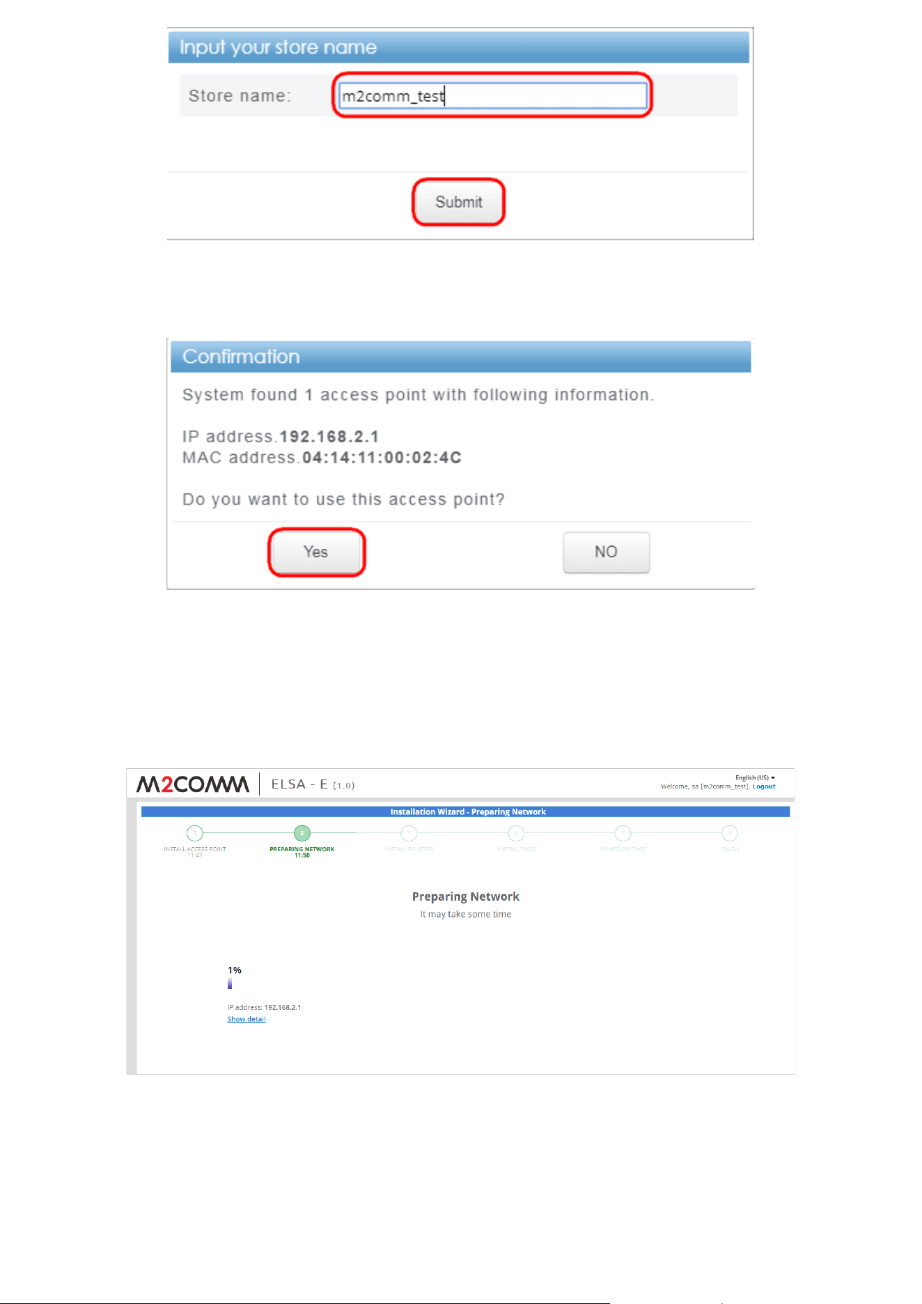
Input the store name, and press Submit
ELSA system will find the connected AP, and press “Yes” to confirm
• Preparing the Network
ELSA system will start to find the available wireless channel to use, and the whole process will take 1 hour.
Press “Show detail” for more information.
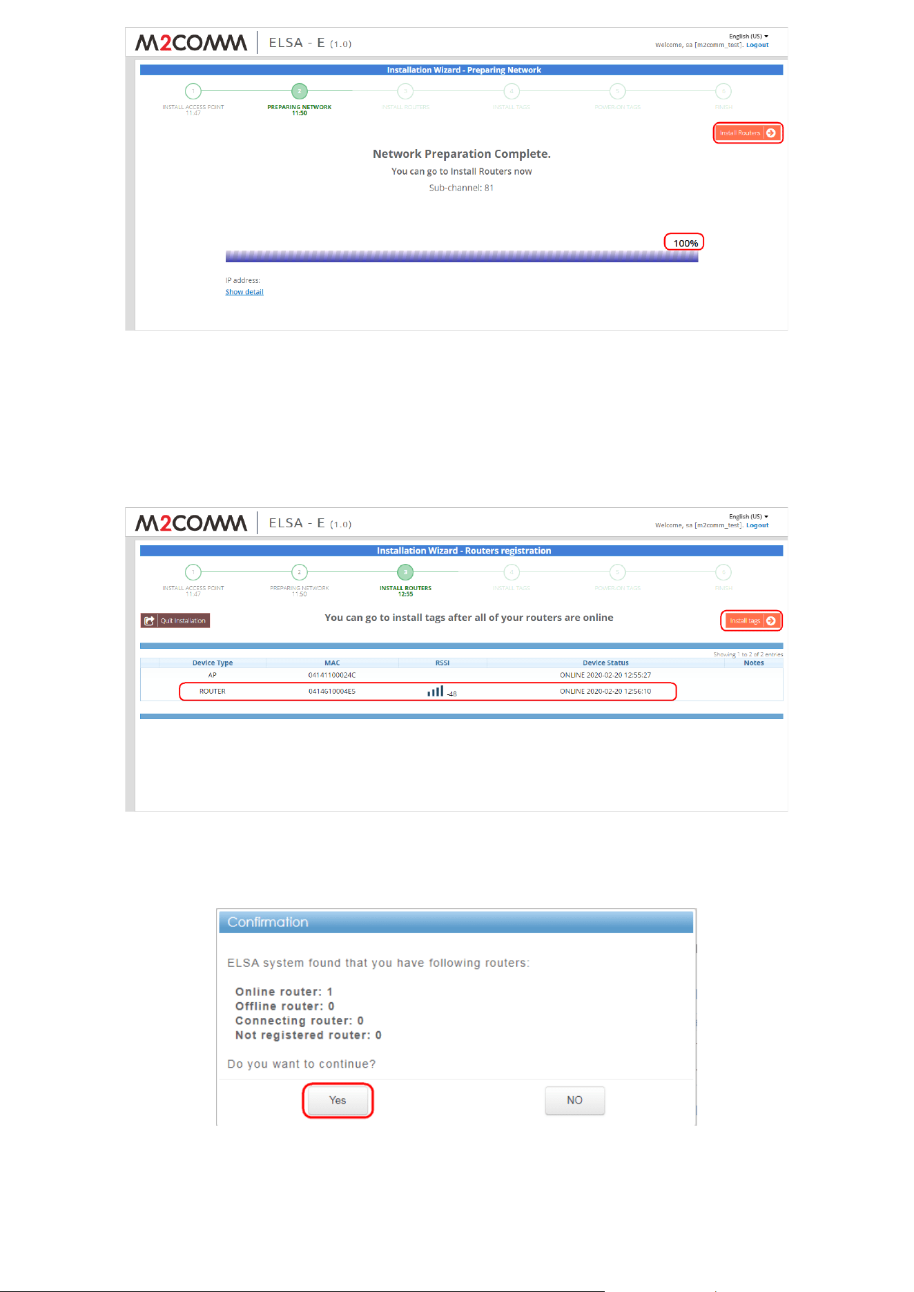
16
Press “Install Routers” for next step, when the progress bar reaches to 100%
• Install Router
Power on the Router
After the ELSA system install the Router automatically, press “Install tags”
Press “Yes” to confirm the device status and enter to next step
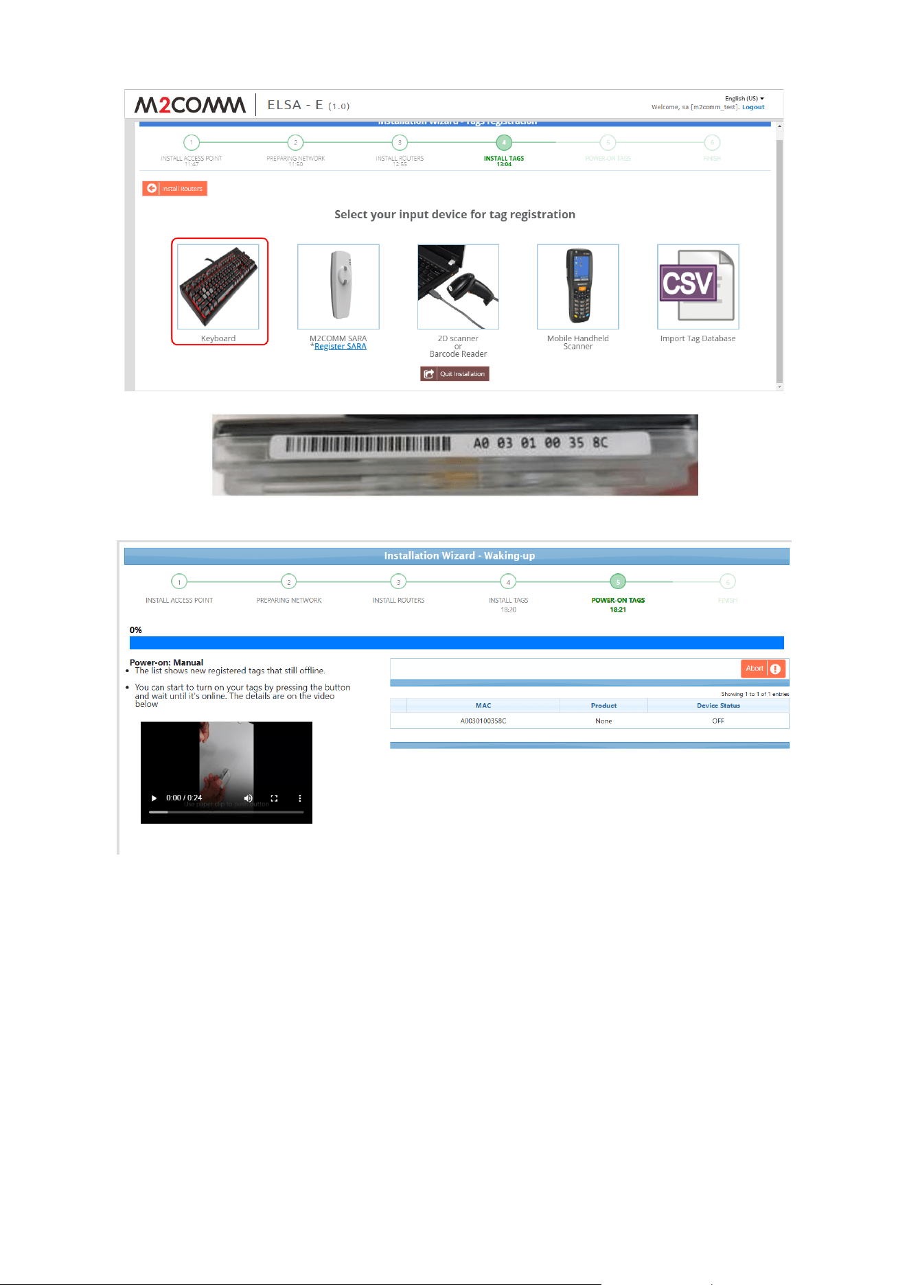
17
• Install Tags
Select “Keyboard” to input the MAC address posted on the bottom side of the ESL
Check “Without product” and Press “Power-on”
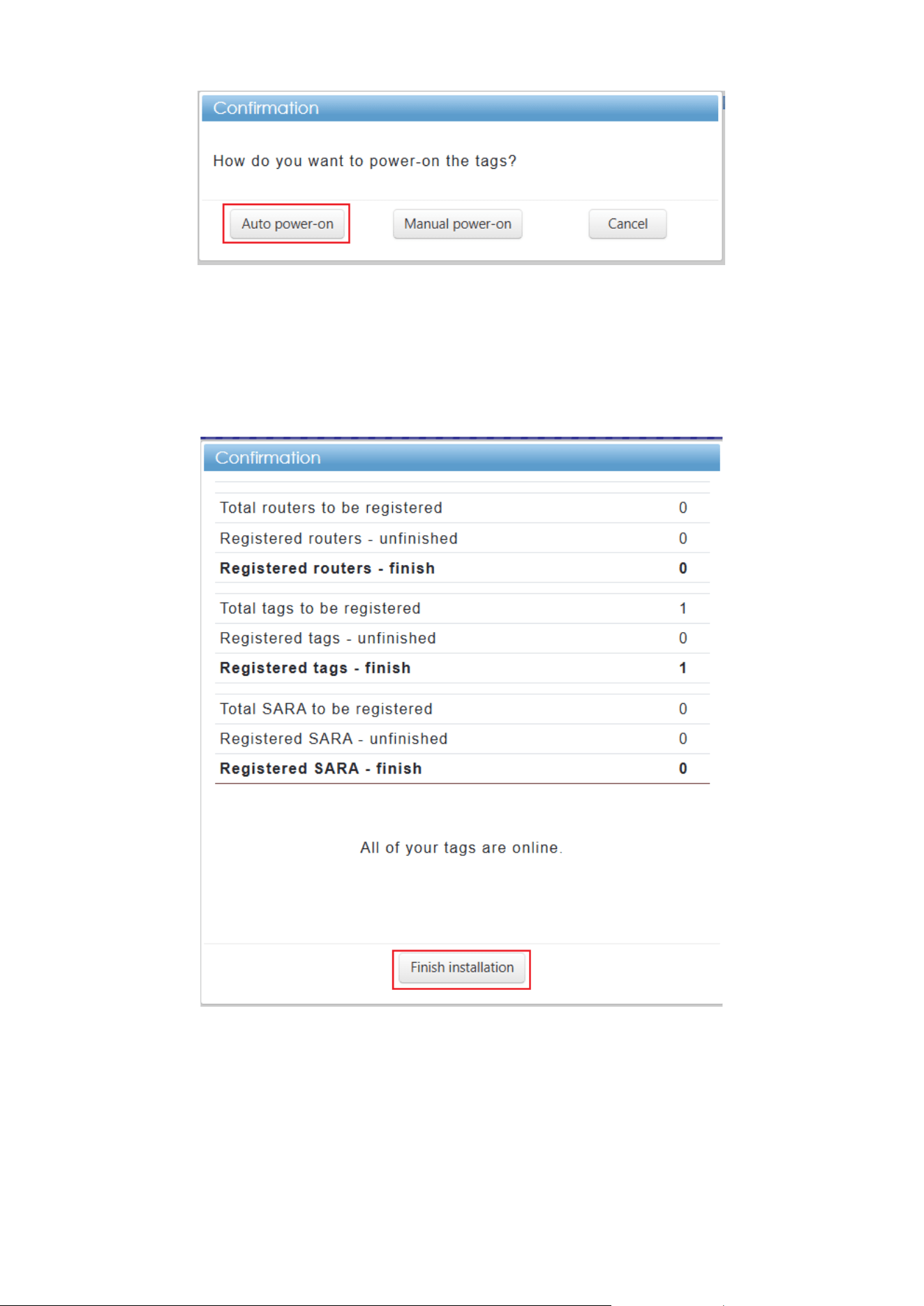
18
• Power ON Tags
Select “Auto power-on”
Wait for ESL to show the “wakeup” page
• Finish
After several minutes, the ELSA web will show “register finish” page
Press “Finish” to leave the installation wizard and back to ELSA dashboard
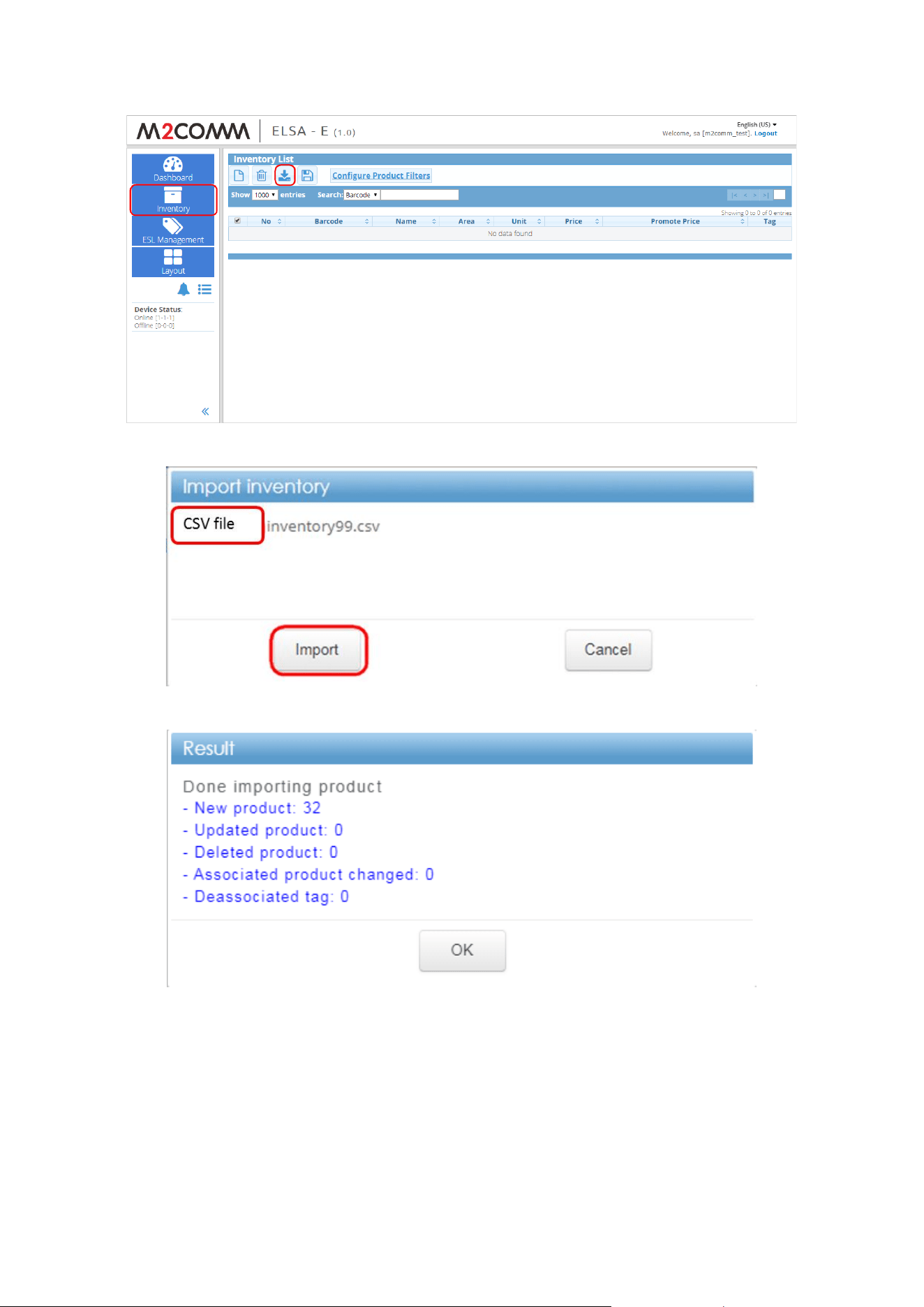
19
Show the image on ELSA-E 2.7’’ ESL
Load the CSV file to import the inventory list first.
Switch to “Inventory” page, and press “Import”
Select the CSV file, “inventory99.csv” and press “Import”
Press “OK” to finish the inventory importing
20
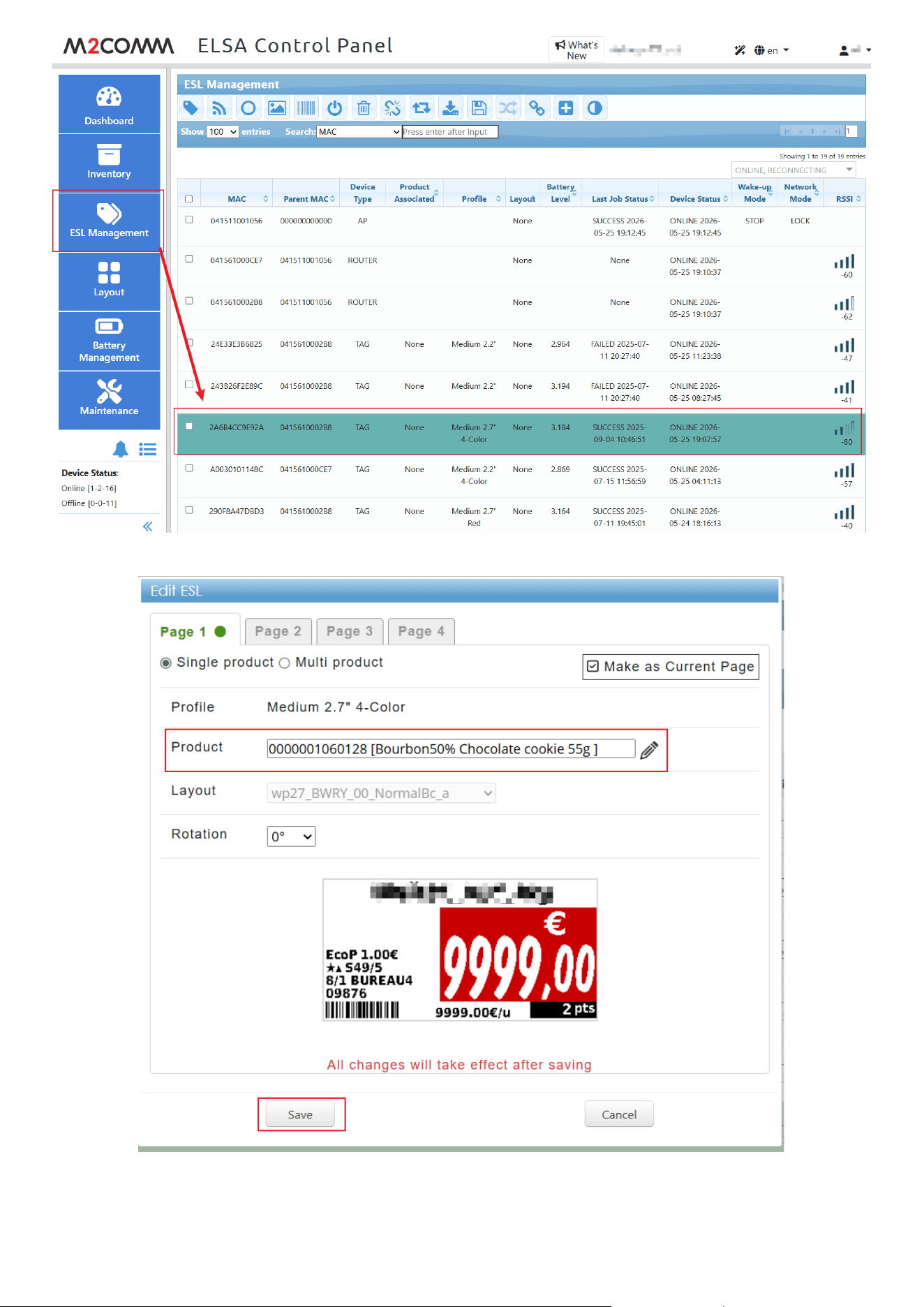
Switch to “ESL Management” page, and double click the 2.7’’ESL
Select any one of the product, and press “Save”
21
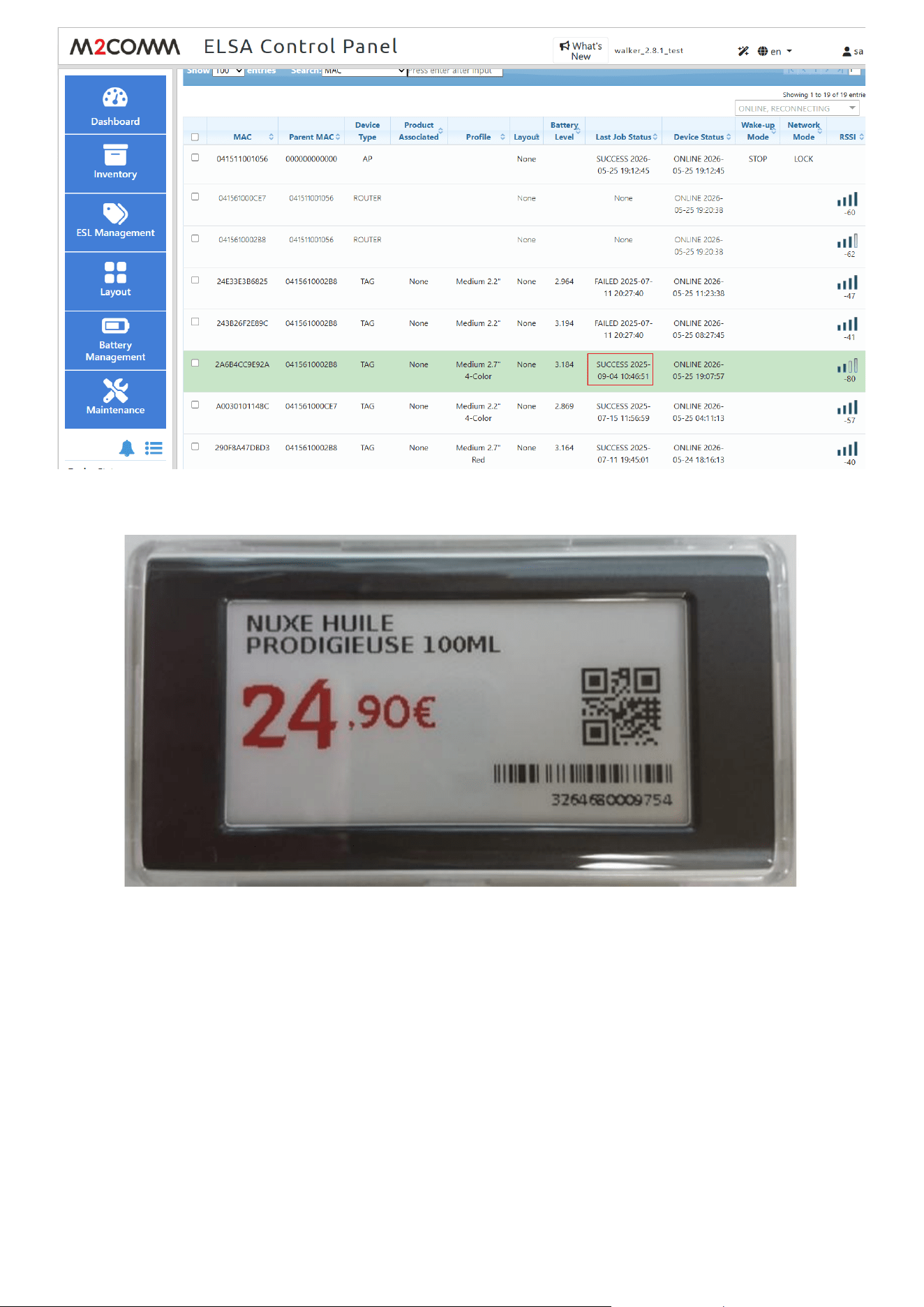
Waiting for the job status become from “Processing” to “SUCCESS”
2.7” ESL shown with image
22
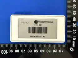
How to Display FCC ID Label(After certification, display it on the "Pairing Page)
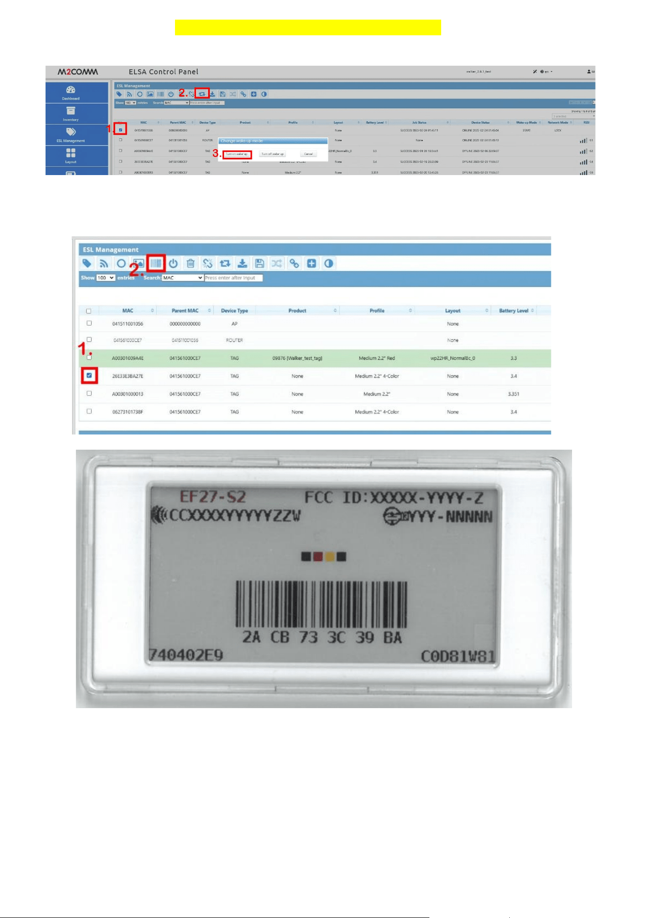
1. Wake Up the Tag: Ensure the EPD is not blank or shows a "sleep mark" (red/black square in the top-left corner).
⚫ If “sleep mark” present, please activate wake-up mode from ELSA WEB until ED removes the "sleep mark."
Active wake-up mode from ELSA web
2. Switch Screens: Switch the EPD display to the "Pairing Page
⚫ Select the ED from ELSA WEB, then click the "Show Barcode" button.
⚫ The ED will be preset to display the "Pairing Page" upon shipment.
2.7” ESL FCC ID display results

23
Battery Caution:
The elements of the instructional safeguard shall be as follows:
- element 1a: not available
- element 2: “Do not ingest battery, Chemical Burn Hazard” or equivalent wording
- element 3: the following or equivalent text
[The remote control supplied with] This product contains a coin / button cell battery. If the coin / button cell battery is
swallowed, it can cause severe internal burns in just 2 hours and can lead to death.
- element 4: the following or equivalent text
Keep new and used batteries away from children
If the battery compartment does not close securely, stop using the product and keep it away from children.
If you think batteries might have been swallowed or placed inside any part of the body, seek immediate medical attention.
FCC Statement:
This device complies with part 15 of the FCC Rules. Operation is subject to the following two conditions:
(1) This device may not cause harmful interference, and
(2) This device must accept any interference received, including interference that may cause undesired operation.
NOTE: This equipment has been tested and found to comply with the limits for a Class B digital device, pursuant to part 15 of the FCC Rules.
These limits are designed to provide reasonable protection against harmful interference in a residential installation.
This equipment generates, uses and can radiate radio frequency energy and, if not installed and used in accordance with the instructions,
may cause harmful interference to radio communications. However, there is no guarantee that interference will not occur in a particular
installation.
If this equipment does cause harmful interference to radio or television reception, which can be determined by turning the equipment off and
on, the user is encouraged to try to correct the interference by one or more of the following measures:
—Reorient or relocate the receiving antenna.
—Increase the separation between the equipment and receiver.
—Connect the equipment into an outlet on a circuit different from that to which the receiver is connected.
—Consult the dealer or an experienced radio/TV technician for help.
Changes or modifications not expressly approved by the party responsible for compliance could void the user’s authority to operate the
equipment.
This equipment complies with FCC radiation exposure limits set forth for an uncontrolled environment. This equipment should be installed
and operated with a minimum distance of 20 cm between the radiator and a human body.
NCC Statement:
Technical Regulations for Low-Power Radio-Frequency Devices
Without prior approval granted by the NCC, no company, firm, or user shall alter the frequency, increase the transmitting power, or modify
the original characteristics or functions of any low-power radio-frequency device that has obtained certification.
The use of low-power radio-frequency devices shall not affect flight safety nor interfere with legal communications. In the event that
interference is found, the user shall immediately cease operation and shall not resume use until the interference has been eliminated. The
aforementioned legal communications refer to radio communications operated in accordance with the Telecommunications Management Act.
Low-power radio-frequency devices must tolerate interference from legal communications or from industrial, scientific, and medical radio-
wave radiating equipment.
M2COMMUNICATION Inc. 17 Floor, No. 32 Gaotie 2
nd
Road, Zhubei City, Hsinchu County 302, Taiwan (R.O.C.)
Tel: +886 3 657 8939 Fax: +886 3 657 6909 http://www.m2comm.co
SALES AND SUPPORT: info@m2comm.co
Copyright © 2017 M2COMMUNICATION Inc. All rights reserved. This document is the property of M2COMMUNICATION Inc. It contains information
which is confidential and proprietary to M2COMMUNICATION Inc. No part of this document may be copied, reproduced or disclosed to third parties
without the prior written consent of M2COMMUNICATION Inc. (Document number: PB-ELSA-Q001)