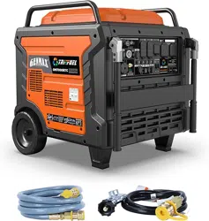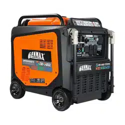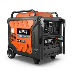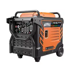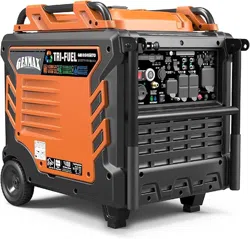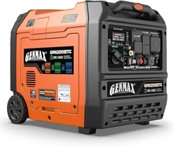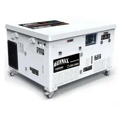
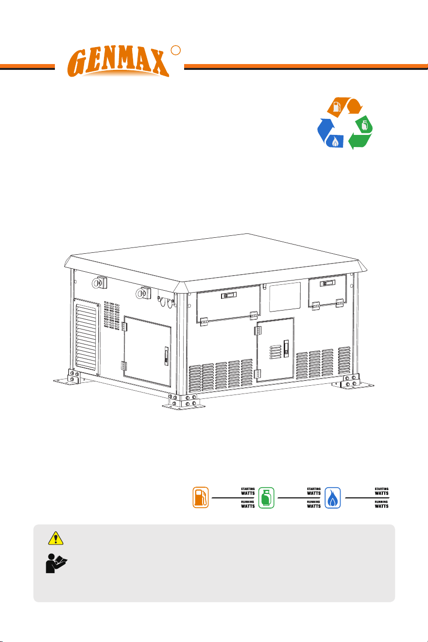
INVERTER GENERATOR
USER'S MANUAL
R
GENMAX GENERATOR
This manual contains important information regarding safety. Operation,
maintenance and storage of this product. Before use, read carefully and
understand all cautions, warnings, instructions and product labels. Failure to do
so could result in serious personal injury and/or property damage.
WARNING: SAVE THIS MANUAL FOR FUTURE REFERENCE
GM14000i-HSB
GASOLINE INVERTER GENERATOR
TRI-FUEL
14000
13000
12500
11500
11000
10000

- 1 -
Thank you very much for choosing generator set product manufactured by our Company!
This Manual will instruct you how to operate and use the generator set safely and properly.
Please be sure to read it carefully before using.
All technical data and diagrammatic presentations in this User’s Manual are consistent with
the latest product at the time of publication.
Due to the revision and other changes, contents of this Manual may be slightly different from
actual situation. The Company is entitled to revise it at any time, and the revised version will
be developed without prior notice, please understand that. The copyright of this User's
Manual belongs to the Company, and this Manual is not allowed to be reproduced without
written consent of the Company, violators must be prosecuted.
This Manual is a permanent part of the generator set. If the generator set is resold, the
Manual will be resold together with the generator set.
TABLE OF CONTENTS
SAFETY .............................................................................................2
NAMES OF COMPONENTS ..............................................................................6
ASSEMBLY(FIXED).................................................................................................8
ASSEMBLY(WHEEL)...............................................................................................9
CONTROL FUNCTIONS......................................................................................10
PREPARATIONS ..............................................................................................14
OPERATION ......................................................................................18
USING THE GENERATOR ................................................................................24
SERVICE AND MAINTENANCE ......................................................................26
STORAGE AND TRANSPORT .............................................................................30
TROUBLESHOOTING .......................................................................................3 1
TECHNICAL PARAMETERS ...............................................................................33
- 2 -
SAFETY
Personal and property safeties of you and
others are very vital. Please read the Safety
Warning in the User's Manual and the decals
of the generator set carefully.
The Safety Warning can alert you to those
potential hazards that could harm you and
others. In front of each Safety Warning, there
is one of four words “DANGER”, “WARNING”,
“ATTENTION”, and “CAREFUL”. Details are
as follows:
DANGER
Failure to follow the instruction will result in
being in peril of your life or extremely
serious injury.
WARNING
Failure to follow the instruction will result in
being in peril of your life or very
serious injury.
CAREFUL
Failure to follow the instruction will result in
minor injury.
ATTENTION
Failure to follow the instruction will result in
the damage to your generator set and
other properties.
SAFETY PRECAUTIONS
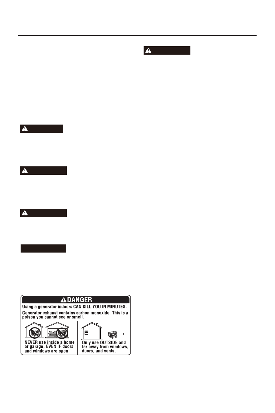
Engine exhaust contains carbon monoxide, a
poisonous gas that could kill you in minutes.
You CANNOT smell it, see it, or taste it. Even
if you do not smell exhaust fumes, you could
still be exposed to carbon monoxide gas.
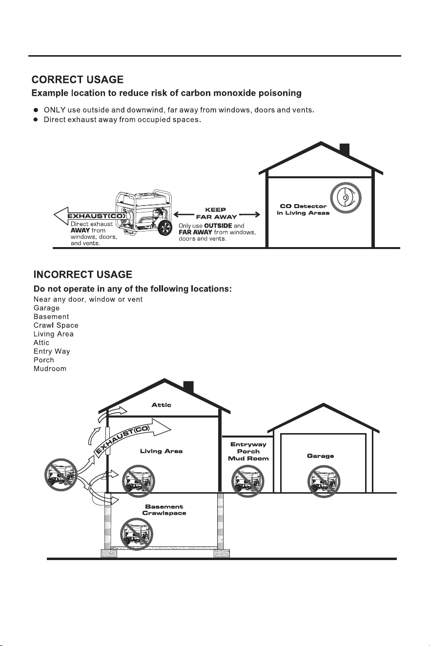
● Operate this product ONLY outside far
away from windows, doors and vents to
reduce the risk of carbon monoxide gas
from accumulating and potentially being
drawn towards occupied spaces.
● Install battery-operated carbon monoxide
alarms or plug-in carbon monoxide alarms
with battery back-up according to the
manufacturer's instructions. Smoke alarms
cannot detect carbon monoxide gas.
● DO NOT run this product inside homes,
garages, basements, crawlspaces, sheds,
or other partially-enclosed spaces even if
using fans or opening doors and windows
for ventilation. Carbon monoxide can
quickly build up in these spaces and can
linger for hours, even after this product has
shut off.
● ALWAYS place this product downwind and
point the engine exhaust away from
occupied spaces. If you start to feel sick,
dizzy, or weak while using this product,
shut it off and get to fresh air RIGHT
AWAY. See a doctor. You may have carbon
monoxide poisoning.
● If you start to feel sick, dizzy or weak while
using the portable generator, you may
have carbon monoxide poisoning. Get out
si de t o fr esh air immed ia tely an d
emergency medical assistance.. Very high
levels of CO can rapidly cause victims to
lose consciousness before they can
rescue themselves. DO NOT attempt to
shut off the generator before moving to
fresh air. Entering an enclosed space
where a generator is or has been running
may put you at greater risk of CO
poisoning.
WARNING
- 3 -
SAFETY

- 4 -
SAFETY
WHEN ADDING OR DRAINING GASOLINE
Turn the generator engine OFF and let it cool
for at least 2 minutes before removing the
fuel cap. Loosen the cap slowly to relieve
pressure in the tank.
● Fill or drain fuel tank outdoors.
● DO NOT overfill the tank. Allow space for
fuel expansion.
● If fuel spills, wipe it up and let the area dry
before starting the engine.
● Keep fuel away from sparks, open flames,
heat, and other ignition sources.
WHEN STARTING EQUIPMENT
● Ensure spark plug, muffler, fuel cap, and
air cleaner are in place.
● DO NOT crank engine with spark plug
removed.
WHEN OPERATING EQUIPMENT
● DO NOT operate this product inside any
building, carport, porch, mobile enclosure,
marine applications, or shed.
● DO NOT tip engine or equipment at an
angle that causes fuel to spill.
● DO NOT stop the engine by moving the
choke control the to "Start" position.
● DO NOT exceed the generator's wattage
capacity.
● Start the generator and the let engine
stabilize before connecting electrical loads.
● Connect electrical loads in the OFF
position, then turn ON for operation.
● Turn electrical loads OFF and disconnect
from the generator before stopping the
generator.
ATTENTION
Improper treatment of the generator could
damage it and shorten its life.
● U s e g e n e ra t o r o n l y f o r in t e n d e d
applications.
● If you have questions about intended use,
ask a dealer.
● Operate generator only on solid, level
surfaces.
● DO NOT expose the generator to
excessive moisture, dust, dirt, or corrosive
vapors.
● DO NOT insert any objects through cooling
slots.
● If connected devices overheat, turn them
off and disco nn ect them f rom the
generator.
BEFORE USING THE GENERATOR
● In order to operate the generator correctly,
be familiar with the operation of the various
components and master the method of
shutting down the generator quickly.
● Without proper instructions and directions,
no one is allowed to operate this machine.
It is strictly prohibited for newborns, young
children, t h e e l d e r l y, peop l e w i t h
disabilities, and other vulnerable groups to
operate. Otherwise, it will become a cause
of serious accidents and machine damage.
● Never use the generator to power medical
support equipment.
● Please never modify the generator.
● Please do not use in rain or in areas with
water. There is a risk of electric shock
when using generators and connected
appliances that have been soaked in rain
or water, or when operating with wet
hands.
● Please never connect wires from the power
company. It can cause malfunctions in the
mach i n e a n d c o n n e c t ed e lectric a l
equipment, becoming the cause of fire or
personal accidents.
● The use of generators has laws and
regulations, please comply with labor safety
and health regulations, fire protection laws,
electrical industry laws, etc.
● Please do not connect parallel operation
terminals except for dedicated wires. There
is a risk of electric shock.
● Check fuel lines, tank, cap, and fittings
frequently for cracks or leaks; replace if
necessary.
● DO NOT light a cigarette or smoke
anything.

- 5 -
SAFETY
PARALLEL KIT PRECAUTIONS
To prevent serious injury, death and damage
to generators and/or equipment due to
electric shock and fire:
● Follow Parallel Kit instructions provided
with Kit for connection and use of a Parallel
Kit.
● Only connect two identical Inverter
Generators together using a Parallel Kit.
● Connect Parallel Kit only to terminals
marked "Parallel Outlets" on the front of the
Generator.
● Do not remove or connect a Parallel Kit
while the Generator is running.
● Do not use a Parallel Kit that is attached to
only one Generator.
SAFETY PRECAUTIONS FOR GASOLINE
AND GASOLINE VAPOR
● Fire and explosion hazard. Gasoline is
highly explosive and flammable and can
cause severe burns or death.
● Fire and Burn Hazard. NEVER loosen or
remove the fuel cap while the generator is
running. Turn the unit off and allow it to cool
for at least five minutes before adding
gasoline. Loosen the fuel cap slowly.
● In case of a gasoline fire, do not attempt to
extinguish the flame unless the engine/fuel
control switch is in the OFF position.
Introducing an extinguisher to a generator
with an open fuel valve could create an
explosion hazard.
LIQUID PETROLEUM GAS
(LPG/PROPANE)
Fire and explosion hazard. Never use a gas
container, LPG/propane hose, propane
cylinder or any other fuel item that appears
to be damaged. If there is a strong smell of
propane while operating the generator, fully
close the propane cylinder valve
immediately. Once the propane is off, use
soapy water to check for leaks on the hose
and connections on the tank valve and the
generator. Do not smoke or light a cigarette
or check for leaks using any open flame
source such as a match or lighter. If a leak
is found, contact a qualified technician to
inspect and repair the LPG/ propane system
before using the generator.
NATURAL GAS (NG)
Fire and explosion hazard. Never use a
natural gas supply line, natural gas hose, or
any other fuel item that appears to be
damaged. If there is a strong smell of natural
gas while operating the generator, close off
all gas sources immediately. Once the
natural gas is off, use soapy water to check
for leaks on the hose and connections on the
branch supply and the generator. Do not
smoke or light a cigarette or check for leaks
using any open flame source such as a
match or lighter. If a leak is found, contact a
qualified plumber to inspect and repair the
natural gas system before using the
generator.
- 6 -
NAMES OF COMPONENTS
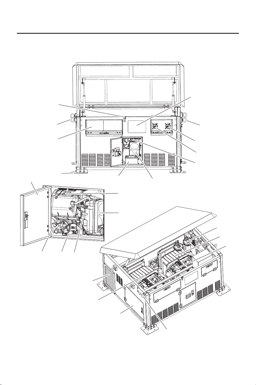
STATEMENT: The illustrations used in this manual are intended as representative reference
views only.
Before operating your generator, you must read and understand the manual and
familiarize yourself with the safe operation practices.
A
B
C
D
H
G2
E
B
F2
F1
N
K1
G1
Q1
P1
O1
L
M
N
K2
J
I
O2
U
- 7 -
NAMES OF COMPONENTS
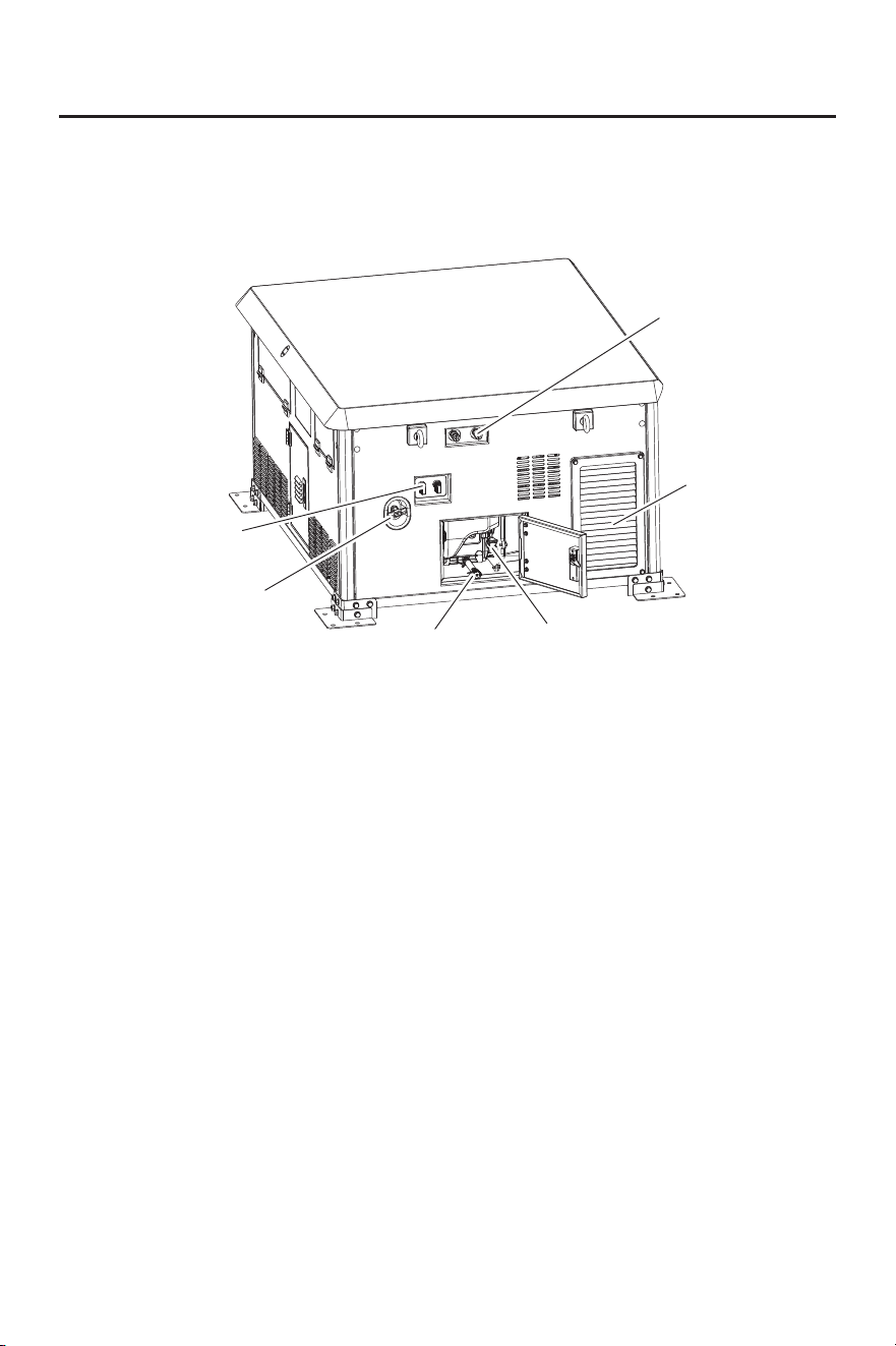
STATEMENT: The illustrations used in this manual are intended as representative reference
views only.
Before operating your generator, you must read and understand the manual and
familiarize yourself with the safe operation practices.
R
M
Q2
P2
T
S
A. Lock With Cover
B. Lifting Ring
C. Control Panel
D. Install Feet
E. Digital Display Table
F1. Fuel Source Switch(Engine No.1)
F2. Fuel Source Switch(Engine No.2)
G1. Air Filter(Engine No.1)
G2. Air Filter(Engine No.2)
H. Battery
I. Fuel regulator
J. Engine No.2
K1. Spark Plug(Engine No.1)
K2. Spark Plug(Engine No.2)
L. Exhaust Port
M. Engine No.1
N. Access Door(Engine No.1)
O1. Carburetor(Engine No.1)
O2. Carburetor(Engine No.2)
P1. Oil Drain Hose(Engine No.1)
P2. Oil Drain Hose(Engine No.2)
Q1. Oil Dipstick(Engine No.1)
Q2. Oil Dipstick(Engine No.2)
R. LPG/NG Inlet
S. Fuel Inlet
T. Recoil Start Handle
U. Load Outlet Port
- 8 -
ASSEMBLY(FIXED)
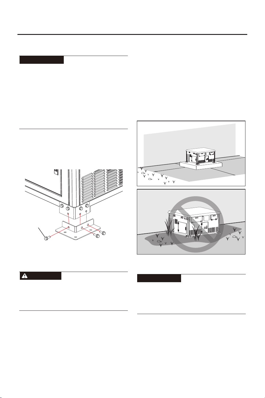
This product requires assembly. Do not
attempt to operate this product if any items in
the INCLUDED LIST are already assembled
when you remove the carton contents. These
items are not assembled by the manufacturer
and should require customer assembly. Using
an improperly assembled product can be
hazardous and could result in serious
personal injury.
ATTENTION
INSTALL FEET
M8*20 Bolt
SITE PREP VERIFICATION
Align the mounting holes of the feet with the
mounting holes at the bottom of the generator
and secure them with bolts. (If there are other
installation methods, you don't need to install
this foot)
DANGER
Automatic start-up. Disconnect utility power
and render unit inoperable before working on
unit. Failure to do so will result in death or
serious injury.
Generator must be installed to allow
unimpeded airflow into and out of generator.
Mechanical and gravity outdoor air intake
openings for air distribution and supply
systems must be located not less than 10 ft
(3.05 m) horizontally from generator
enclosure. See Section 401.4 in the ICC
Mechanical Code for additional information.
Verify all shrubs or tall grasses within 5 ft
(0.91 m) of intake and discharge louvers on
the sides of the enclosure have been
removed. Install generator on high ground
where water levels will not rise and endanger
it. This unit must not operate in or be
subjected to standing water. Verify all
potential water sources such as water
sprinklers, roof run-off, rain gutter
downspouts, and sump pump discharges are
directed away from unit.
WALL
GROUNG
5ft
5ft
0.5ft
5ft
WALL
GROUNG
FIXED GENERATOR
ATTENTION
All components that need to be installed
before using this product must be installed in
place and regularly checked for loose
connections at the installation points.
Secure the generator feet to the platform
using bolts. Alternative fastening methods are
acceptable, provided they ensure the
generator remains completely immobile
during operation. SAFETY NOTE: All
fasteners must be properly rated and
installed to prevent hazardous movement
or vibration.
- 9 -
ASSEMBLY(WHEEL)
This product requires assembly. Do not
attempt to operate this product if any items in
the INCLUDED LIST are already assembled
when you remove the carton contents. These
items are not assembled by the manufacturer
and should require customer assembly. Using
an improperly assembled product can be
hazardous and could result in serious
personal injury.
ATTENTION
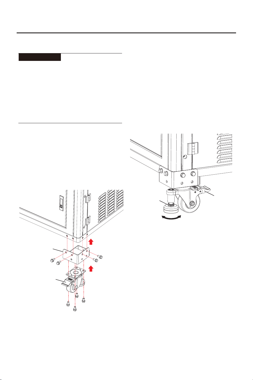
INSTALL WHEEL
The operation steps are as follows:
① Remove the original mounting base from
the generator;
② Assemble the wheels with the mounting
base;
③ Reinstall the assembled wheel - attached
base back to the generator.
See the figure for details.
Mounting Base
Wheel
Adjustable Nut
Descend Rise
Lock
After the wheels are installed, follow these
steps for operation:
For moving the generator: Use a wrench to
turn the adjustment nut on the support leg
counterclockwise to lift the support leg off the
ground, then unlock the wheel lock to move
the unit.
For fixed placement or starting the
generator: First lock the wheel lock tightly,
then use a wrench to turn the adjustment nut
on the support leg clockwise. Lower the
support leg until it touches the ground and the
wheels are completely off the ground.
- 10 -
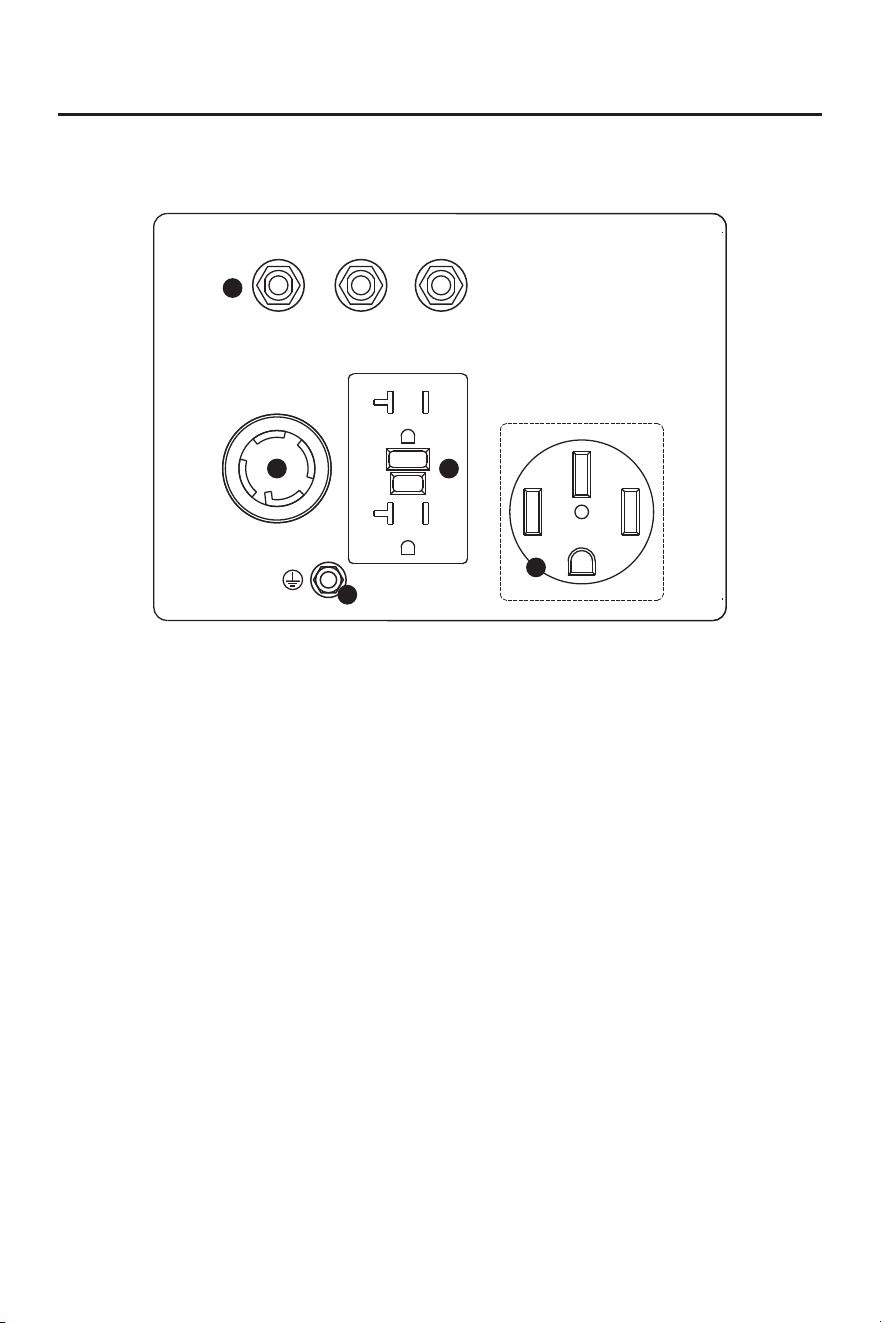
CONTROL PANEL 1
20A 30A
AC 120/240V 30A
AC 120V 20A
AC 120/240V 50A
30A
1
2
3
4
5
① Circuit Breakers: The circuit breakers
protect individual circuits from electrical
overload.
② 120/240V AC 30A L14-30R Outlet: The
outlet is capable of carrying a maximum of
30 amps.
③ 120V AC 20A 5-20R Outlet: The outlet is
capable of carrying a maximum of 20
amps.
④ 120/240V AC 50A 14-50R Outlet:
Receptacle can supply a maximum of 50
Amps.
⑤ Ground Terminal: The ground terminal is
used to externally ground the inverter.
CONTROL FUNCTIONS
- 11 -
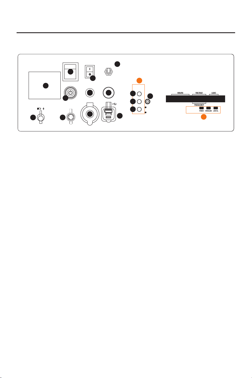
CONTROL PANEL 2
ENGINE #2
MAIN BREAKER
MAIN SW.
ON
OFF
LOW IDLE
ON
OFF
START/STOP
DC 12V 8.3A
8A
DC BREAKER
USB
RESET
PUSH TO
MAINTENANCE
REQUIRED SEE
MANUAL
CARBON
MONOXIDE
DETECTED
CO ALERT
ENGINE #1
LOW OIL
OVERLOAD
POWER
ENGINE
#1
#1
+
#2
ENGINE
#2
AUTO GEN
START
1
2
3
5
4
7
6
9
8
10
11
12
13
14
15
① Main Circuit Breaker: The main circuit
breaker controls total output of all outlets to
protect the generator from overload or
short circuit.
② Main Switch: Manage battery power and
shutdown.
③ Low Idle: When turned to the ON position,
the engine will sense the load needed and
run at a slower RPM to save fuel.
④ START/STOP Switch: Press this button,
the engine can start and stop.
⑤ Engine Mode: Select the engine start/run
mode.
⑥ DC Cigarette Lighter Outlet: 12V DC
8.3A.
⑦ DC Protector: If the generator is overload,
the DC protector will trip to block current.
⑧ AUTO GEN START: The communication
interface for automatically starting and
stopping the generator. Used to connect
equipment with automatic start stop
function. (Automatic control equipment is
sold separately)
⑨ Battery Charging Port: Charge the
generator battery.
⑩ If the inverter is overloaded, the Reset:
reset breaker will trip. The engine will
continue to run, but there will be no output
from the inverter. Unplug the devices and
reduce the load. Push in the reset breaker
to reset it.
⑪ USB Duplex: 5V DC, type-A and type-C
connectors.
⑫ Low Oil Alarm: Indicates low oil level.
⑬ Overload Alarm: Indicates that the inverter
is overloaded.
⑭ Power Indicator: Indicates the inverter is
ready to be used.
⑮ CO Alarm: Flashing red light: dangerous
levels of carbon monoxide gas have built
up leave immediately until area has aired
out. Move generator to well-ventilated area
before operation. Flashing yellow light:
carbon monoxide sensor malfunction.
Sensor needs service.
⑯ Engine No.1 running status indicator light
group.
⑰ Engine No.2 running status indicator light
group.
16
17
CONTROL FUNCTIONS
- 12 -
CONTROL FUNCTIONS
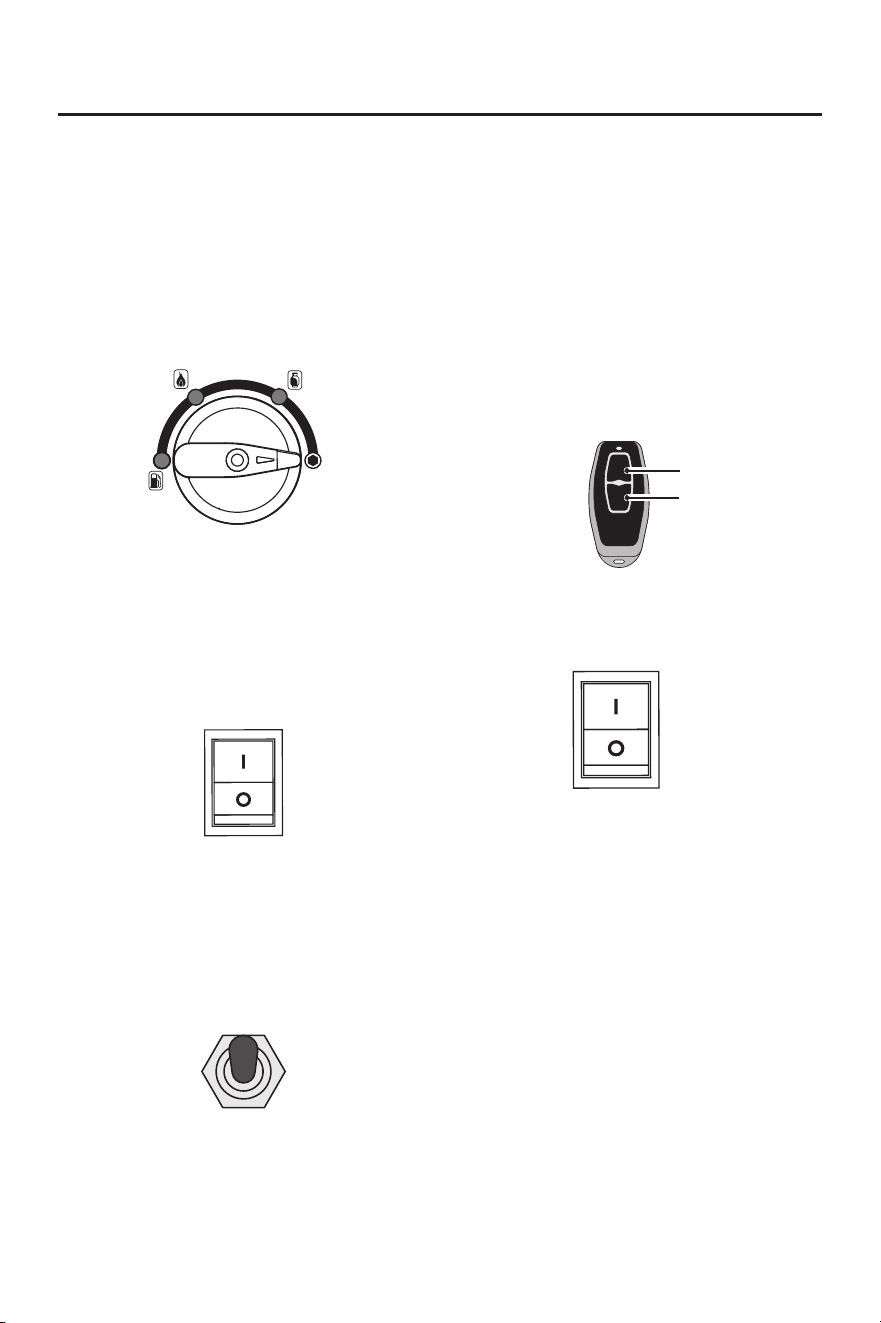
Main Switch (Engine Switch)
OFF - Ignition circuit is off, the engine
stopped running.
ON - Ignition circuit is on, the start the
engine.
MAIN.SW
ON
OFF
Note: The product you purchased may not
have these configurations, please refer to
the actual product.
Energy-Saving Switch (LOW IDLE)
LOW IDLE
ON
OFF
1) "ON”
When energy saving switch is switched to
"ON" position engine speed is reduced when
the generator is under light load. This feature
will reduce fuel consumption and noise.
FUEL SOURCE
Gasoline
Propane(LPG)
Methane(NG)
Fuel Source
OFF - Turn off fuel supply
Propane(LPG) - Using propane as fuel.
Methane(NG) - Using methane as fuel.
Gasoline - Using gasoline as fuel.
Remote Control
OFF - Generator outage.
ON - Generator operation.
Remote Control Pairing:
1. Long press the start button for more than 5
seconds until the button red indicator is on;
OFF
ON
OFF Button
ON Button
2. Press any key on the remote control;
3. The red indicator of the start button will
blink two or three times and then turns off,
Remote start pairing is successful.
Tip: The remote control delivered with the
generator has been paired successfully.
Engine Mode
#1 - Only start Engine No. 1.
#2 - Only start Engine No. 2.
#1+#2 - Two engines start simultaneously.
ENGINE
#1
#1
+
#2
ENGINE
#2
2) "OFF"
When the energy saving switch is set to the
"OFF" position, the engine will run at rated
speed, regardless of connected load.
- 13 -
CONTROL FUNCTIONS
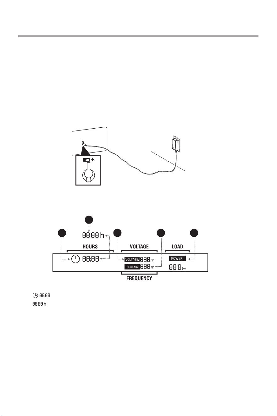
Battery Charging
Keep the generator battery fully charged and ready to use to avoid the need to use the recoil
starter to start the generator manually.
The battery shipped with the generator has been partially charged. A battery may lose some
charge when not in use for prolonged periods of time.
● Once the generator is started, it will immediately charge the battery.
● When the generator is not running, the attached charger can charge the battery.
● Charge in a dry place.
● The charging time should not exceed 30-40 minutes.
Digital Display Center
1
2
3
4
5
① : Represents single run time, goes from 0 at each startup.
② : Represents total operation time of the generator.(Tip: The total operation time
shall start to accumulate after the generator runs for one hour. It will not be displayed
when the generator runs for less than one hour. The total operation time shall be
accumulated by hours.) The two factors ① and ② are displayed alternately every 8
seconds.
③ VOLTAGE: Voltage display: 120V and 240V switch every 16 seconds.
④ FREQUENCY: Frequency display.
⑤ LOAD: Load power display.
- 14 -
PREPARATIONS
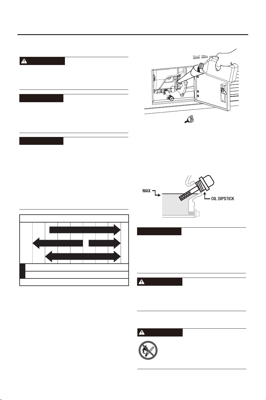
ADD ENGINE OIL
No oil is filled into this generator when being
delivered. Do not start up the generator
without filing sufficient oil.
Your generator was functionally tested in the
factory and may contain minimum residual
oil. Additional oil is required to operate the
unit. Do not overfill.
ATTENTION
The recommended oil type for typical use is
10W-30 automotive oil. However, using the
listed conventional oils shown in the
"Recommended Engine Oil Type" chart may
be used for typical use including the first 5
hours of the break-in run time period of the
engine. If running generator in extreme
temperatures, refer to the "Recommended
Engine Oil Type" chart.
Recommended Engine Oil Type
-20 0 20 40 60 80 100 120
-28.9 -17.8 -6.7 4.4 15.6 26.7 37.8 48.9
℃
℉
Ambient Temperature
10W-30
10W-405W-30
5W-30 Full Synthetic
ATTENTION
1. Confirm that the generator is stopped and
powered off.
2. Open the oil access door.
3. Remove oil dipstick to add oil.
4. Using a funnel, as needed, add the
appropriate type of oil until the oil level is at
the proper level. SAE 10W-30 oil is
recommended for general use. DO NOT
OVERFILL. Replace oil dipstick.
5. Check engine oil level daily and add as
needed.
ATTENTION
Once the oil has been added, a visual check
should show oil about 1-2 threads from
running out of the fill hole. When using the
dipstick to check the oil level, DO NOT screw
in the dipstick while checking.
WARNING
Note: Both Engine No. 1 and Engine No. 2
need to have engine oil added.
This engine is equipped with a low oil shut-off
and will stop when the oil level in the
crankcase falls below a critical level.
CAREFUL
ADD GASOLINE
TO PREVENT SERIOUS INJURY FROM FIRE:
Fill the gasoline tank in a well-ventilated area
away from ignition sources. If the engine is
hot from use, shut the engine off and wait for
it to cool before adding gasoline. Do not
smoke.
WARNING
- 15 -
PREPARATIONS
3. Add an appropriate amount of gasoline to
the fuel tank.
Note: The fuel tank must be placed higher
than the engine to facilitate the normal
operation of the engine.
Do not overfill the gasoline the tank. Overfilling
can result in a fire, explosion, or death.
Gasoline can expand. Do not fill the gasoline
tank to the top. Leave a minimum of 1.5
inches open space. Gasoline fumes are highly
flammable. Do not fill the tank near an open
flame. Always check for gasoline spills.
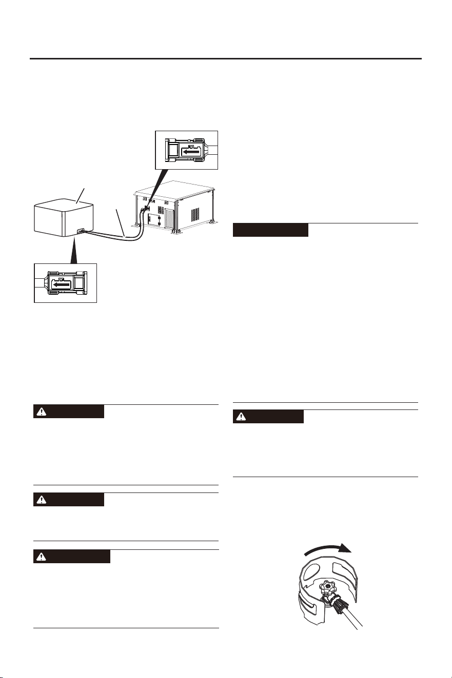
1. Confirm that the generator is stopped and
powered off.
2. Connect fuel tank to generator. (Fuel tank
sold separately)
Tubing Connection Port
Tubing Connection Port
(Indicates fuel flow to the
generator)
(Indicates the outflow of
gasoline from the external
fuel tank)
Fuel Hose
Fuel Tank
Note: Both Engine No. 1 and Engine No. 2
need to be connected to gasoline.
DANGER
Do not place the fuel tank or fuel hose in the
position of the generator exhaust port, as the
temperature at the exhaust port will be
relatively high, and placing it in this position
will be very dangerous.
DANGER
● To ensure the generator runs smoothly,
only fresh, unleaded gasoline is used.
● Never use an oil/gasoline mixture. Never
use old gasoline.
● Avoid getting dirt or water in the gasoline
tank.
● Gasoline can age in the tank and make it
hard to start the generator in the future.
● Never store generator for extended periods
of time with gasoline in the tank.
WARNING
CONNECTING AN LPG TANK
● Confirm that the re-qualification date on the
tank has not expired.
● All new propane tanks must be purged of
air and moisture prior to filling. Used
propane tanks that have not been plugged
or kept closed must also be purged. The
purging process should be done by a
propane tank supplier (propane tanks from
an exchange supplier should have been
purged and filled properly).
● ALWAYS position the propane tank so the
connection between the valve and the gas
inlet will not cause sharp bends or kinks in
the hose.
1. Turn the generator OFF and place on a flat
surface in a well ventilated area.
2. Verify that the LPG tank valve is in the fully
closed position.
Explosion hazard. DO NOT start generator if
you smell propane. ALWAYS fully close the
propane tank valve and disconnect the LPG
hose from the generator when not in use.
ATTENTION
DANGER
Close
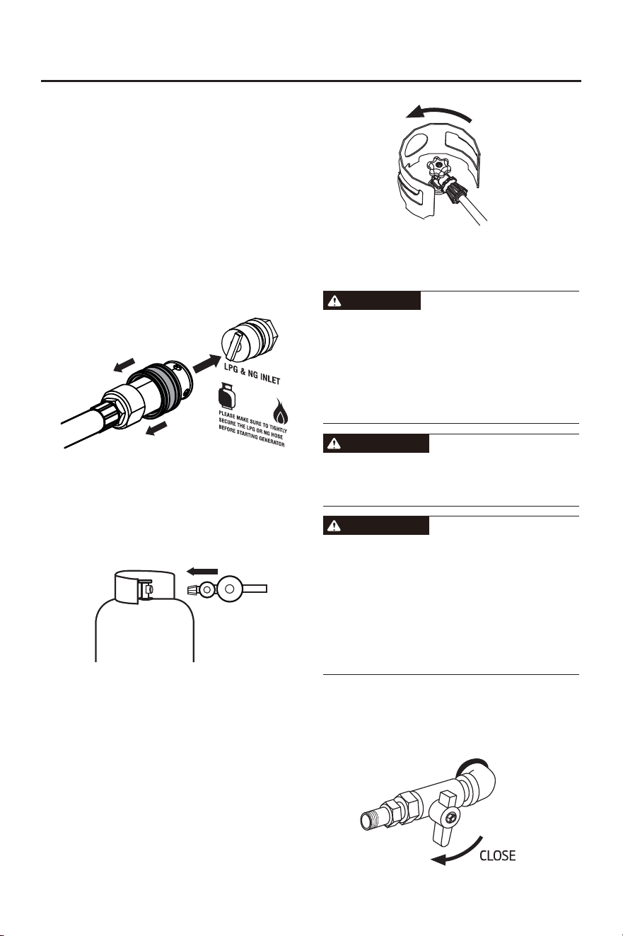
- 16 -
PREPARATIONS
4. Tighten the LPG hose to the
propane/methane inlet of the generator.
IMPORTANT: DO NOT use thread seal tape
or any other type of sealant to seal the LPG
hose connection.
5. Push back the quick connector collet of the
LPG hose, insert it into the generator
propane/methane inlet, loosen the quick
connector sleeve, and make the sleeve
clamp the propane/methane inlet.
3. Remove the cover on the generator
propane inlet.
6. Remove the safety plug or cap from the
LPG tank valve and attach the other end
of the hose to the LPG connector on the
tank. Hand-tighten.
LPG Tank
LPG Hose
7. Turn the LPG tank valve to the fully open
position. Check all connections for leaks
by wetting the fittings with a solution of
soap and water. Bubbles which appear or
bubbles which grow indicate that a leak
exists. If a leak exists at a fitting, turn the
LPG tank valve to the fully closed position
and tighten the fitting. Open the LPG tank
valve and recheck the fitting with the soap
and water solution.
Open
CONNECT THE NATURAL
GAS (NG) SUPPLY LINE
Fire and explosion hazard. Never connect or
disconnect the natural gas hose while the
engine is running. Do not smoke or create
sparks while handling natural gas. Always
turn the engine off and allow the generator to
cool for at least five minutes before
connecting to natural gas.
Never use a natural gas supply line, natural
gas hose, or any other fuel item that appears
to be damaged.
● To reduce the risk of injury, perform a leak
test any time the natural gas hose is
disconnected and reconnected.
● Explosion hazard. If you smell methane, do
not start the generator. Always completely
close natural gas supply line valve and
disconnect natural gas (NG) hose from
generator when not in use.
DANGER
WARNING
WARNING
1. Turn the generator off and allow the engine
to cool for at least five minutes.
2. Verify that the gas is turned off at the
natural gas supply line.
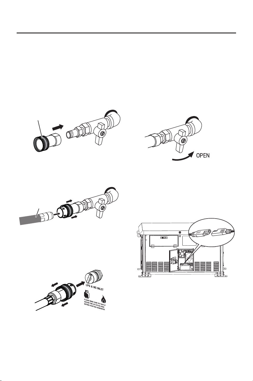
- 17 -
PREPARATIONS
3. Completely unwrap and straighten the
natural gas hose to prevent kinks.
4. Contact your local gas company for
guidance on accessory connection to a
natural gas line. You qualified contractor
must minimally ensure the pipe supply line
threads are clean and in good condition.
Pipe connections must be made using a
gas rated 'dope' or PTFE tape.
Natural Gas Adapter
5. Pull the quick connect collet rearward,
insert the natural gas hose nipple, then
release the collet; ensure a solid
connection is made.
6. Push back the quick connector collet of the
natural gas hose, insert it into the generator
propane/methane inlet, loosen the quick
connector sleeve, and make the sleeve
clamp the propane/methane inlet.
Natural Gas Hose
IMPORTANT: DO NOT use thread seal tape
or any other type of sealant to seal the natural
gas hose connection.
7. Turn the natural gas (NG) supply line valve
to the fully open position. Check all
connections for leaks by wetting the fittings
with a solution of soap and water. Bubbles
which appear or bubbles which grow
indicate that a leak exists. If a leak exists at
a fitting, turn the natural gas (NG) supply
line valve to the fully closed position and
tighten the fitting. Open the natural gas
(NG) supply line valve and recheck the
fitting with the soap and water solution.
CONNECTING THE BATTERY
1. Open the access door.
2. A quick-connect battery plug is pre-installed
on the battery. Remove the cable tie
securing the plugs, align colors, then push
firmly to connect them.
3. Reinstall the maintenance cover.
Note: The generator is equipped with a battery
charging feature. Once the engine is running,
a small current will slowly recharge the battery.
- 18 -
OPERATION
GENERATOR LOCATION
NEVER operate the generator inside any
building, garage, basement, crawlspace,
shed, or enclosure, including the generator
compartment of a recreational vehicle.
NEVER operate or start the generator in the
back of an SUV, camper, trailer, truck bed
(regular sides, flat or other configuration),
under staircases, stairwells, next to walls or
buildings, or any other location that could limit
airflow or trap exhaust.
DO NOT operate or store the generator in wet
weather conditions such as rain or snow.
Using a generator in wet conditions could
result in serious injury or death due to
electrocution.
Generators must have a minimum of 5 feet
(1.5 m) of clearance from all combustible
material.
Generators must also have a minimum of 5
feet (1.5 m) of airflow clearance on all sides to
allow for adequate cooling, maintenance, and
service.
Always place the generator in a well-ventilated
area. NEVER place the generator near air
intake vents or where exhaust fumes could be
drawn into occupied or confined spaces.
Always carefully consider wind and air
currents when positioning the generator.
Always allow generators to properly cool
before transport or for storage purposes.
Failure to follow proper safety precautions
may result in personal injury, damage to the
generator, and void your warranty.
During operation, the muffler and exhaust
fumes will become hot. If there is inadequate
cooling space or if the generator is blocked
or enclosed, temperatures can rise quickly
and may lead to a fire.
WARNING
WARNING
STARTING THE GENERATOR
1. Place the generator in a safe, appropriate
location.
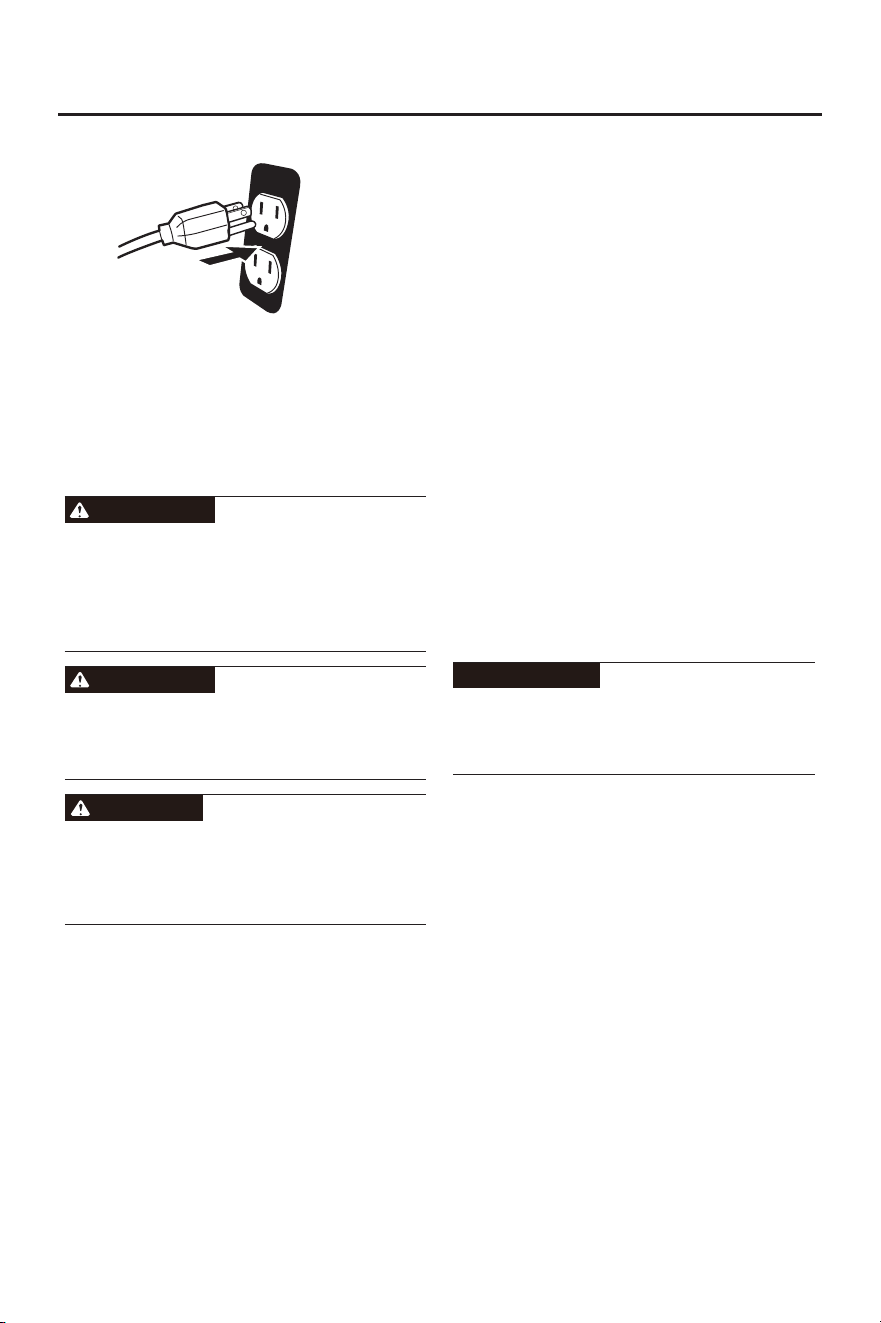
2. Disconnect all electrical loads from the
generator. Never start or stop the generator
with electrical devices plugged in or turned
on.
3. Check oil and fuel levels. If needed add oil,
refill the LP gas cylinder, add gasoline, or
contact your natural gas utility company.
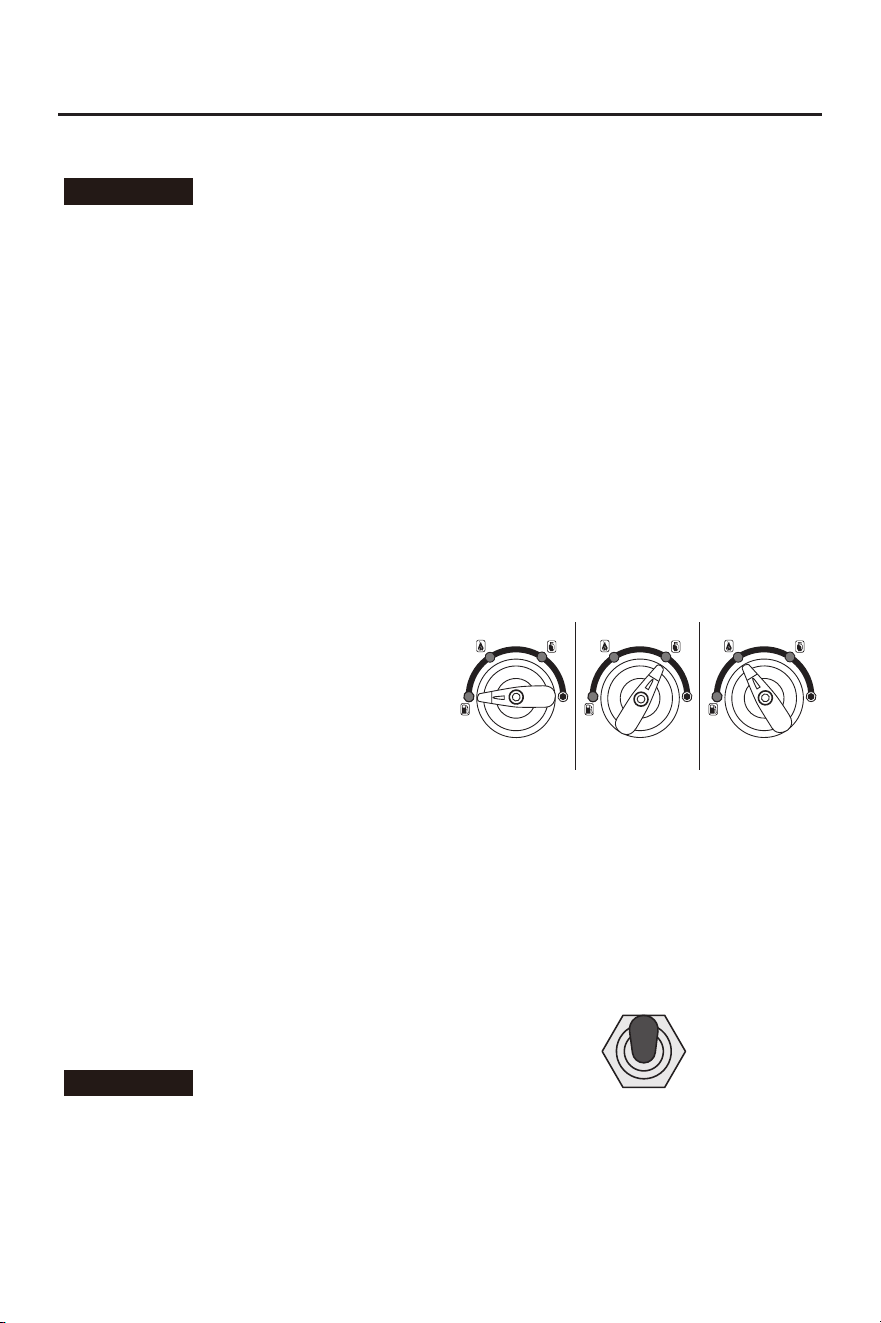
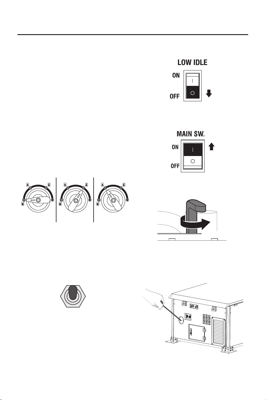
4. Turn the Fuel Switch to desired fuel source.
● When the Fuel Switch is in the Gasoline
position, the generator is ready to start with
Gasoline.
● When the Fuel Switch is in the LPG
position, the generator is ready to start with
propane.
● When the Fuel Switch is in the Natural
Gas(NG) position, the generator is ready to
start with methane.
STARTING ON GASOLINE STARTING ON LPG STARTING ON NG
NOTE: Engine No. 1 and Engine No. 2
must use the same fuel. DO NOT use
different fuels to start the generator.
5. Select Operating Mode: Choose to start
Engine No. 1 (#1), Engine No. 2 (#2), or
operate in parallel (#1+#2) based on your
electricity needs.
ENGINE
#1
#1
+
#2
ENGINE
#2
- 19 -
OPERATION
NOTE: If only one engine is started, the
output power will only be half of the total
rated power of the generator. If parallel
operation is selected, the total rated power of
the generator will be output.
Before starting, Engine No. 1, Engine No. 2 or
parallel operation must be selected. Do not
switch modes when the generator is running,
otherwise it may damage the generator.
WARNING
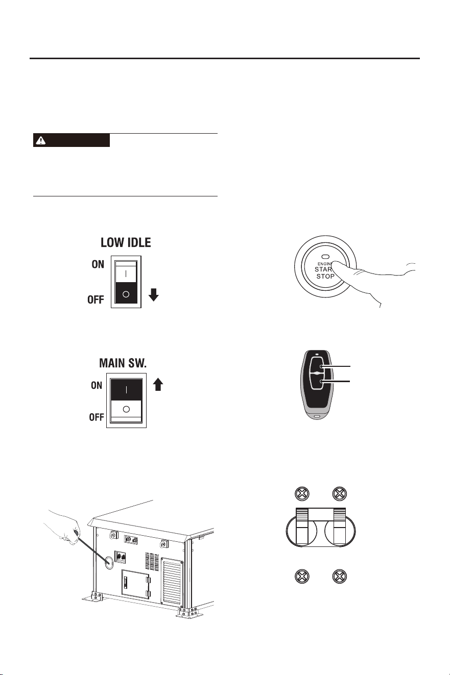
6. Press LOW IDLE to "OFF".
7. Press Main Switch to "ON".
8. Choose the Starting Method
Recoil Start: Firmly grasp and pull the recoil
handle slowly until you feel resistance, let it
retract then pull swiftly.
NOTE: Only Engine No. 2(#2) or parallel
(#1+#2) can be selected for recoil start. Do
not attempt to switch to Engine No. 1 after
starting, nor switch the mode to Engine No. 1
to attempt recoil start of the generator.
Push Button Start: Press the start button for
1-3 seconds, then release, to start the
generator.
Remote Start: Push and hold the ON button
on the remote start key fob for one second.
OFF
ON
OFF Button
ON Button
9. After about 3-5 seconds of startup, the
running light will turn green and the circuit
breaker will automatically close. At this
time, the generator can output normally.
10. When the generator output stabilizes, you
can safely connect loads to the control
panel receptacles.
NOTE: In the parallel operation mode, if you
use the recoil start, the No. 2 engine will be
started first. Approximately 5 minutes later,
the No. 1 engine will automatically start. Do
not insert any load during this period.
- 20 -
OPERATION
3. Turn off and disconnect all electrical
devices and stop the engine. Compare
device requirements to generator rating
and reduce the total wattage of connected
devices if necessary. Move anything that
may be limiting generator ventilation away.
4. Check if any circuit breakers have tripped
and make sure that ALL circuit breakers
are reset before starting the generator
again.
5. Restart the engine and reconnect devices
while being careful to not overload the
generator.
Low Oil Indicator
1. If the engine oil level is too low, the LOW
OIL light turns on and the engine will
automatically shut off.
2. The engine cannot be restarted until the
proper amount of oil has been added. Add
the appropriate type of oil until the oil level
is at the proper level. SAE 10w-30 oil is
recommended for general use.
NOTE: Verify that all devices are turned off
before connecting them to the generator.
NOTE: Make sure that the wattage
requirements for all connected devices are in
line with your generator’s capabilities.
When using the generator with propane(or
methane), make sure there is no possible
ignition source close to the generator.
WARNING
Fire and explosion hazard. Always turn the
propane(or methane) tank valve to the fully
closed position if not running the generator on
propane(or methane).
DANGER
Overload Indicator
Note: The OVERLOAD light may turn on for
a few seconds as a large device starts. This
is normal for loads approaching the capacity
of this generator.
1.The total combined load through the outlets
on the generator must not exceed the
running power of the unit.
2. If the OVERLOAD light turns on and the
generator stops producing power, it has
been overloaded.
Fuel Switching
WARNING
Always perform fuel switching changeover
with the generator completely shut down and
cooled. Ensure fuel lines are properly purged
and connections are leak-free before
restarting to prevent fire or explosion hazards.
Do not run the engine with too little oil.
Engine will shut off if engine oil level is too
low.
Low Idle
1. Turn on a low idle mode to limit noise and
fuel consumption with a light generator
load.
2. Turn off the low idle mode to run the engine
at full speed under the following conditions:
● Starting the generator.
● If the load exceeds 50%, it is recommended
to turn off the low idle mode.
ATTENTION
RECOIL START
(The battery is dead)
When the generator battery is low on power,
it is not possible to start the generator by
pressing the button or using the remote key.
In this case, the engine needs to be started
using the recoil start method. Once the
generator starts running, a small current will
be generated to charge the battery.
- 21 -
OPERATION
1. Place the generator in a safe, appropriate
location.
2. Disconnect all electrical loads from the
generator. Never start or stop the generator
with electrical devices plugged in or turned
on.
3. Check oil and fuel levels. If needed add oil,
refill the LP gas cylinder, add gasoline, or
contact your natural gas utility company.
4. Turn the Fuel Switch to desired fuel source.
● When the Fuel Switch is in the Gasoline
position, the generator is ready to start with
Gasoline.
● When the Fuel Switch is in the LPG
position, the generator is ready to start with
propane.
● When the Fuel Switch is in the Natural
Gas(NG) position, the generator is ready to
start with methane.
STARTING ON GASOLINE STARTING ON LPG STARTING ON NG
NOTE: Engine No. 1 and Engine No. 2
must use the same fuel. DO NOT use
different fuels to start the generator.
5. Select Engine No. 2 (#2) or the parallel (#1
+ #2).
6. Press LOW IDLE to "OFF".
7. Press Main Switch to "ON".
NOTE: Only Engine No. 2(#2) or parallel
(#1+#2) can be selected for recoil start. Do
not attempt to switch to Engine No. 1 after
starting, nor switch the mode to Engine No. 1
to attempt recoil start of the generator.
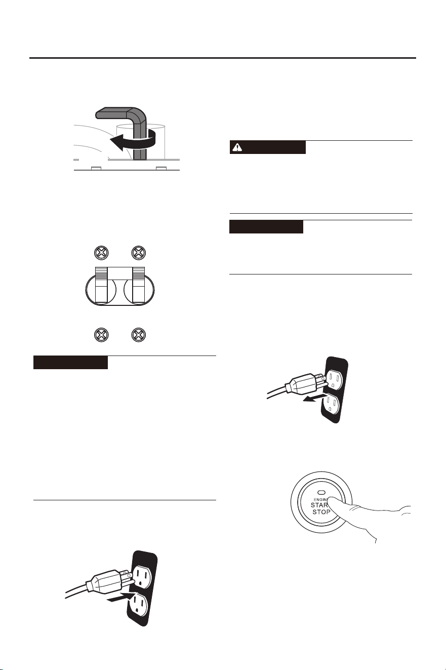
8. Turn the choke valve of Engine No. 2 to
“CLOSE”.
CLOSED
9. Firmly grasp and pull the recoil handle
slowly until you feel resistance, let it retract
then pull swiftly.
ENGINE
#1
#1
+
#2
ENGINE
#2
- 22 -
OPERATION
10. Turn the choke valve of Engine No. 2 to
“OPEN”.
OPEN
11. After about 3-5 seconds of startup, the
running light will turn green and the
circuit breaker will automatically close. At
this time, the generator can output
normally.
Select Mode #2: After approximately 3 to 5
seconds of startup, the operation indicator
light will turn green and the circuit breaker
will automatically close. At this point, the
generator can start to output electricity
normally.
Select Mode #1 + #2: Engine No. 2 will start
first. Approximately 5 minutes later, Engine
No. 1 will automatically start. Once both
engines are properly activated, the circuit
breaker will automatically close.
ATTENTION
12. When the generator output stabilizes, you
can safely connect loads to the control
panel receptacles.
NOTE: Verify that all devices are turned off
before connecting them to the generator.
NOTE: Make sure that the wattage
requirements for all connected devices are in
line with your generator’s capabilities.
To switch to # 1 mode, please turn off the
generator before switching to the operating
mode. Do not switch modes while the
generator is running, as it may damage the
generator.
WARNING
The No. 1 engine can only be started by
using the button or the remote key. (Electric
start)
ATTENTION
1. Turn off and unplug all connected electrical
loads. Never start or stop the generator
with electrical devices plugged in or turned
on.
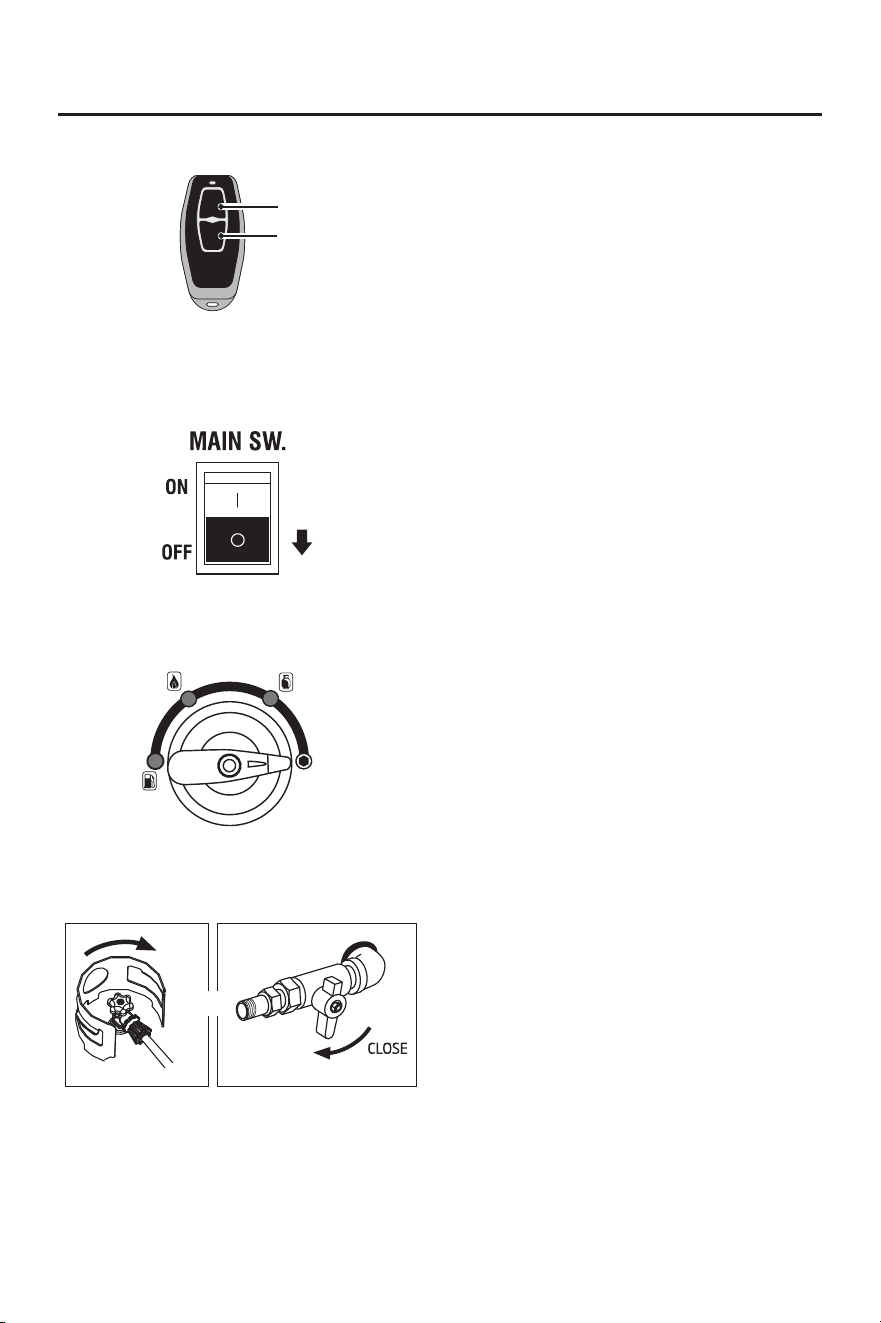
STOPPING THE GENERATOR
2. Select the Stopping Mode:
Button Stop: Press the button to turn off the
generator.
Remote Stop: Hold down the OFF button
on the remote start key for one second.
- 23 -
OPERATION
3. Press the Main Switch to "OFF".
lf not used for more than 48 hours, please
turn off the Main Switch.
4. Turn the Fuel Selector knob to the OFF
position.
7. Remove or consume all untreated
gasoline if you plan to store the generator
longer than 3 months.
5. If using LPG or NG fuel, close the valve
when not in use.
Close
or
6. After the generator has completely cooled
down, remove propane(or methane) hose
if applicable and store the generator in a
cool, dry, sheltered storage area.
8. If the generator is not used for a long time,
please disconnect the battery wiring.
OFF
ON
OFF Button
ON Button
- 24 -
USING THE GENERATOR
SERVICE ENVIRONMENT OF THE
GENERATOR
● Applicable temperature: 23℉(-5℃ )~
104℉(40℃);
● Applicable humidity: below 95%;
● Applicable altitude: regions below 1,500 m
(It shall be used by reducing power in
regions above 1,000 m).
Standard atmospheric condition
● Ambient temperature Tr: 298k (77℉)(25°C)
● Relative air humidity Φr: 30%.
● Absolute atmospheric pressure Pr: 100kPa
When actual environmental condition is
inconsistent with the condition of output
power of the generator set:
● Every 41℉(5°C) of increase in ambient
temperature will reduce the power of
generator by about 2%
● Every 30% of increase in relative humidity
of air will reduce the power of generator by
about 1.5%
● Every 300 m rising of ASL will reduce the
power the generator by about 4.5%
GENERATOR WIRING
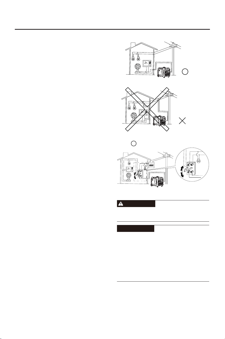
● When the generator is connected to
household power source as a backup
power supply, the connection shall be
carried out by a professional electrician or
a person familiar with electricity.
● After connecting the load to the generator,
check carefully whether electrical
connection is safe and reliable. Improper
electrical connection may cause generator
damage, burning or fire.
● Avoid connecting this generator to
commercial power outlet.
● When extending the cable, be sure not to
exceed its length.
① 60m cross-section area is 1 .5mm²
② 100m cross-section area is 2.5mm²
● The appearance of extension cable shall
be protected by a layer of tough and
elastic rubber cover (IEC25) or other
substitutes.
Good
Prohibited
Good
Ail electrical equipment shall be disconnected
before inserting the plug.
● Make sure that all electrical equipment,
including wires and plugs, are in good
condition before connecting to the
generator;
● Make sure that all loads driven by the
generator are within rated load range;
● Make sure that load current is within rated
current range of rated socket.
Tip: Make sure that the generator set is
grounded, and if electrical equipment
requires grounding, the generator set must
be grounded.
Connection of AC power
WARNING
ATTENTION

- 25 -
USING THE GENERATOR
① Start up the engine;
② Turn energy-saving switch to “ON” ;
③ Insert the plug into AC outlet;
④ Make sure that AC indicator is lit up;
⑤ Switch on electrical equipment.
Tip: Before increasing engine speed, low idle
switch must be switched to “OFF”. If the
generator set supplies power to multi loads or
electrical equipment, start from large to small
according to the size of each electrical
equipment.
Generator Grounding
In order to prevent any damage to the
generator caused by electric shock or
improper electrical application, it is
recommended that the generator is grounded
with good conductor with insulating sheath.
① Please use grounding wire with sufficient
electrical energy capacity;
② Connect one end of grounding wire
reliable to grounding bolt on control panel
of the generator set;
③ Insert grounding body (iron rod with a
diameter of 5 ~ 10mm) 200mm below into
the earth and lead it out with conductor;
④ Connect the other end of the grounding
wire reliable to the led wire of grounding
body.
RANGE OF APPLICATION
Before using the generator, please make sure
that total load is within rated load range of the
generator, otherwise the generator may be
damaged.
Tip:
● AC and DC can be used at the same time,
but total power amount shall not exceed
rated output power.
● When total power exceeds rated power,
overload indicator will light up.
- 26 -
SERVICE AND MAINTENANCE
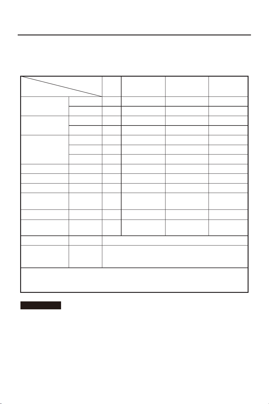
Good maintenance and service is the best guarantee for safe, economical and reliable
operation. It also contributes to environmental protection.
In order to keep the generator in good condition, you must inspect and maintain it regularly.
The maintenance schedule is as follows:
Maintenance cycle
Item
Each
First in 1 month
or 20 hours
Then every three
months or every
50 hours
100 hours per
year or use
Engine oil
Gearbox gear
Oil (if any)
Air cleaner
element
Settling cup (if any)
Spark plug
Spark eliminator
Idle speed
(if any)**
Valve clearance**
Fuel tank and
fuel filter***
Fuel line
Cylinder head,
piston
Displacement < 225cc, every 125 hours; displacement
capacity ≥ 225cc, every 250 hours.
Check-fill
Replace
Replace
Check oil
Inspection
Clean
Replace
Clean
Clean-adjust
Clean
Check-adjust
Check-adjust
Clean
Inspection
Remove
carbon
deposit**
Every two years (Please replace if ncessary)
√
√ √
√
√ √
√
√
√
√
√*
√
√
√
√
* heseT items shall be replaced if necessary;
** heT se items shall be maintained by the dealer authorized by the Company, unless the
user has proper tools and maintenance ability.
ATTENTION
● If it often works under high temperature or high load, oil shall be changed every 25 hours;
● If it often works in dusty or harsh environment, air cleaner element shall be cleaned every 10
hours. If necessary, the air cleaner element shall be replaced every 25 hours;
● It shall be maintained on spot-inspection or on regularly scheduled inspections;
● If maintenance cycle time has elapsed, perform the maintenance as soon as possible as per
the table above.
- 27 -
SERVICE AND MAINTENANCE
Please shut down the engine first before
performing any maintenance. The engine
shall be placed in a horizontal position. In
order to prevent the engine from starting up,
separate spark plug cap shall be separated
from spark plug.
ENGINE OIL CHANGE
Do not drain the oil immediately after turning
off the generator. During operation, the oil is
very hot and can cause serious burns.
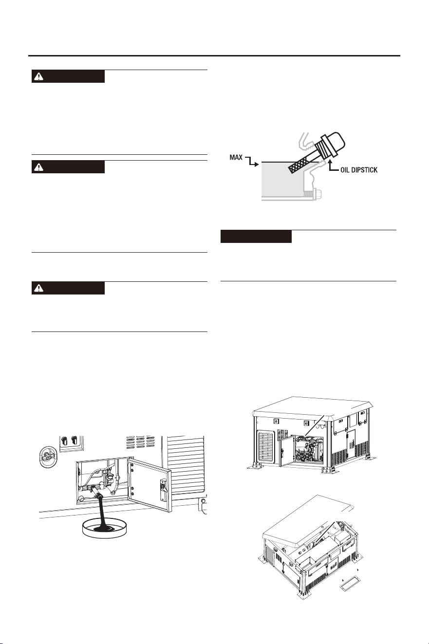
1. Confirm that the generator is stopped and
powered off.
2. Open the oil access door.
3. Find the oil drain hose (to the left of the
dipstick), place an oil basin (or suitable
container), unscrew the cap of the oil hose,
tilt, wait for the oil to drain completely.
Recycle used oil.
Note: Make sure the generator is level when
adding oil to prevent overfilling which could
cause engine damage.
6. Check the oil level. The oil level should be
just below the edge of the hole as shown.
Do not attempt to run the engine with too little
oil. The engine will not start with low or no
engine oil.
ATTENTION
7. Thread the oil dipstick back in clockwise.
Do not use it indoors or use it in a tunnel,
cave or other places ventilated poorly. Make
sure that work area is well ventilated. Exhaust
gas from the engine contains toxic gases,
carbon oxides, and the inhalation can cause
shock, loss of consciousness, and even
death.
WARNING
WARNING
WARNING
4. Replace the oil drain hose cap. Put the oil
drain hose back into the generator.
5. Add the appropriate type of oil until the oil
level is at the proper level. SAE 10w-30 oil
is recommended for general use.
SPARK PLUG MAINTENANCE
NOTE: Engine No. 1 and Engine No. 2 need
to undergo the above maintenance
simultaneously.
1. Confirm that the generator is stopped and
powered off.
2. Open the access door.
#1 ENGINE
Spark Plug
#2 ENGINE
Spark Plug
- 28 -
SERVICE AND MAINTENANCE
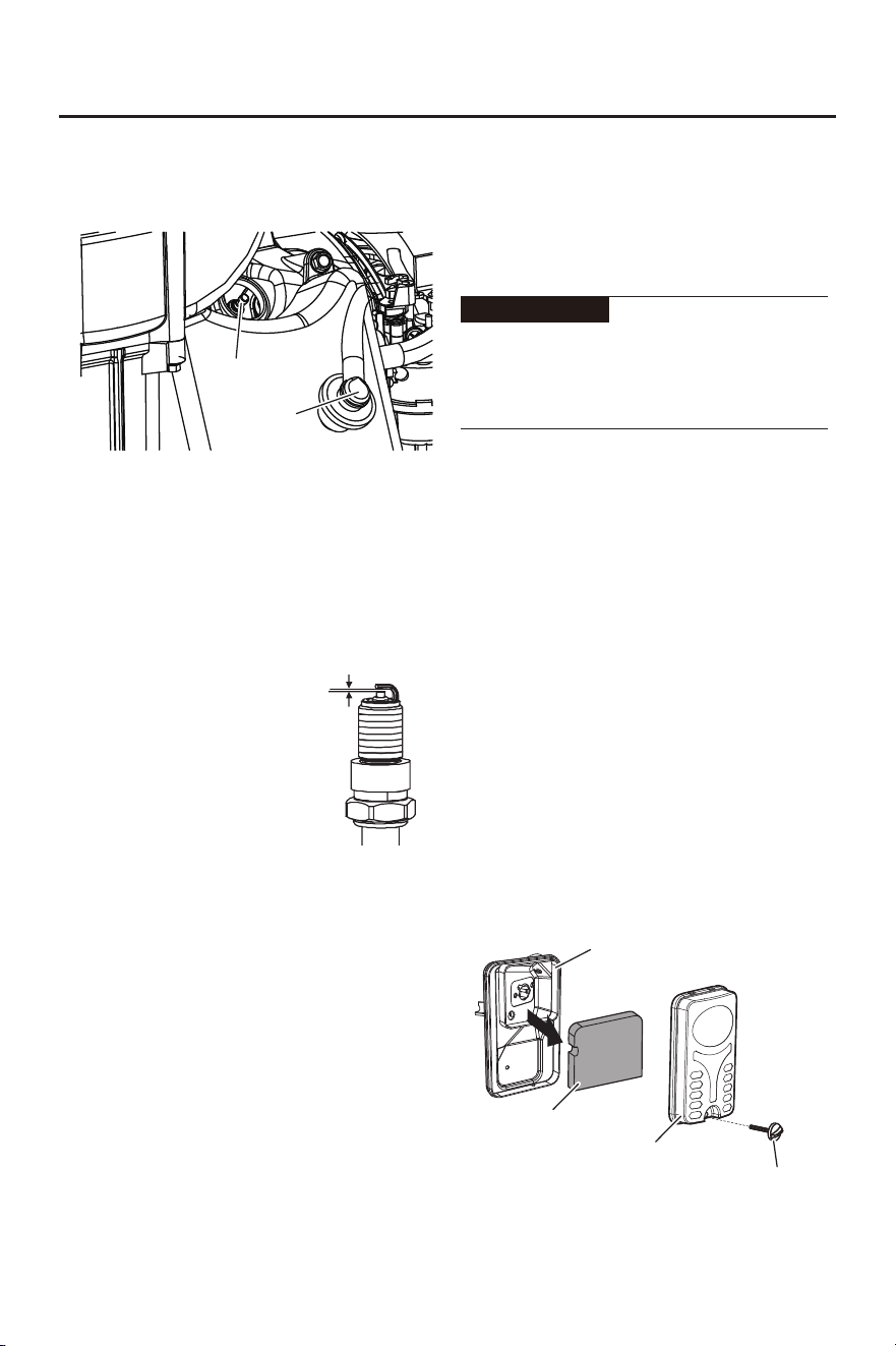
3. Disconnect Spark Plug Cap from the end of
plug. Clean out debris from around Spark
Plug.
Spark Plug
Spark Plug
Cap
4. Using the Spark Plug Wrench, remove the
Spark Plug.
5. Inspect the Spark Plug: If the electrode is
oily, clean it using a clean, dry rag. If the
electrode has deposits on it, clean it with a
brass wire brush. If the white insulator is
cracked or chipped, replace the spark plug.
0.7~0.8mm
Standard spark: BPR6ES
Spark plug gap: 0.7-0.8mm
Tip: The spark plug clearance is required to
be measured by line thickness gauge, which
shall be adjusted if necessary.
6. When installing a new spark plug, adjust
the plug's gap to the specification on the
Specifications Chart. Do not pry against the
center electrode, the spark plug can be
damaged.
7. Apply anti-seize material to Spark Plug
threads. Install the new spark plug or the
cleaned spark plug into the engine.
Spark cold torque: 22 N.m
Tip: If there is no torque wrench when
installing the spark plug, a better estimation
method is to screw it 1/4-1/2 turns by force
after screwing it in place, but the spark plug
shall be screwed to specified torque as soon
as possible.
Tighten the Spark Plug properly. If loose, the
Spark Plug will cause the engine to overheat.
If over tightened, the threads in the engine
block will get damaged.
8. Replace Spark Plug Cap and access door..
NOTE: Engine No. 1 and Engine No. 2 need
to undergo the above maintenance
simultaneously.
ATTENTION
AIR FILTER
Dirty air cleaner may prevent air from flowing
into the carburetor. In order to prevent failure
of the carburetor, please maintain air cleaner
regularly. If being used in a dusty
environment, it shall be maintained
frequently.
1. Confirm that the generator is stopped and
powered off.
2. Open the access door.
3. Unsnap the Air Filter Cover Clip and
remove Air Filter Cover. See the figure
below.
4. Remove Air Filter.
Housing
Bolt
Air Filter Cover
Air Filter
- 29 -
SERVICE AND MAINTENANCE
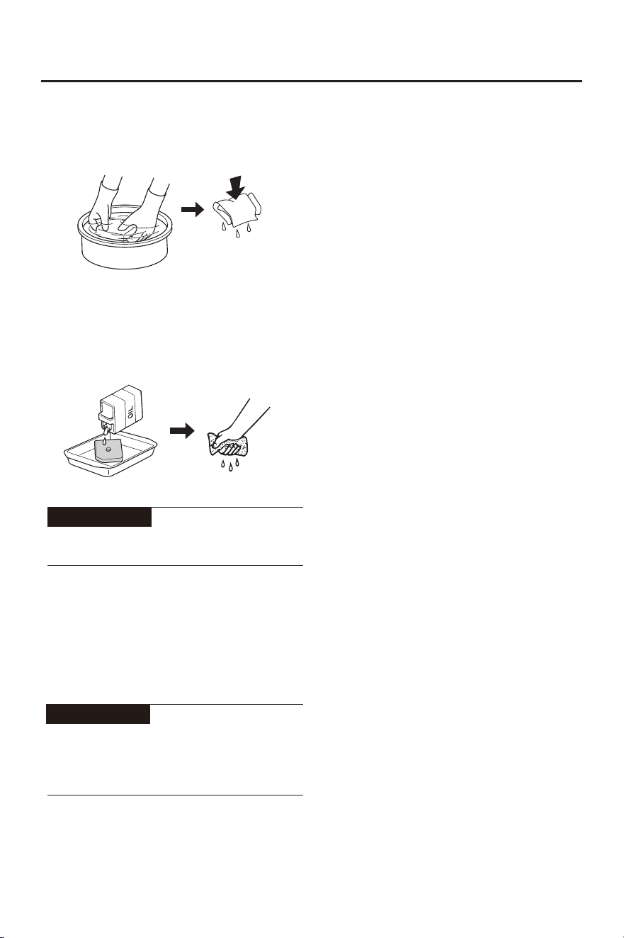
4. Clean the components with cleaning
agent. After cleaning, wrap the
components in a cloth and screw them dry.
5. Drip a few drops of oil to foam filter
element and squeeze off excess oil. The
foam cleaner element shall be wet, but
there shall not be oil dripping.
ATTENTION
Be sure not to twist the foam cleaner element
forcibly to avoid damage.
6. Put foam cleaner element into air cleaner.
7. Reassemble empty air cleaner cap back to
original position, and tighten screws.
Be sure not to start the engine before air
cleaner is assembled, because ti will
generate excessive toxic gas and wear the
cylinder.
ATTENTION
Tip: Make sure that the surface of foam
cleaner element is in close contact with air
cleaner, and there shall be no gap leaking air.
NOTE: Engine No. 1 and Engine No. 2 need
to undergo the above maintenance
simultaneously.
- 30 -
STORAGE AND TRANSPORT
GENERATOR STORAGE
If it is stored long-term, in order to prevent
aging, you shall take some storage
measures.
1. Turn off the generator.
2. Open fuel tank cap, to take out fuel filter
screen. Pump all fuel in fuel tank into
special fuel tank, and then reassemble fuel
tank cap back.
Tip: Do not connect any electrical
equipment. Running time of the engine
depends on remaining fuel in the fuel tank.
3. Unscrew fuel drain bolt on the carburetor,
and drain fuel in the carburetor into special
fuel tank. Tighten fuel drain bolt.
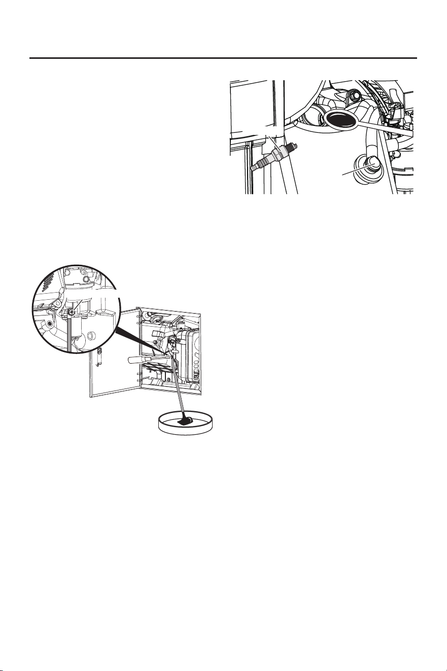
5. Remove the spark plug and pour 5-10ml of
clean oil into the combustion chamber.
Turn the crankshaft a few times to
distribute the oil, then reassemble the
spark plug.
6. Gently pull startup handle until you feel
resistance, allowing both inlet valve and
exhaust valve to be closed.
7. Disconnect the battery.
8. Place the generator set in a clean and dry
area.
GENERATOR TRANSPORT
● When transporting the generator set, it
should be stored separately from the fuel
tank.
● Do not run the generator, and avoid direct
sunlight.
● Do not transport the generator set on rough
road for long time.
PREPARATION FOR USE AFTER
STORAGE
1. Slowly pull the starter cord a few times to
clean oil from the cylinder or to eject any
pump protector from the pump which may
have been added prior to storage.
2. Remove the spark plug from the cylinder.
Wipe oil from the spark plug and return it
to the cylinder and re-tighten.
3. Reconnect the spark plug wire.
4. Refuel engine per earlier instructions in
this manual.
4. Unscrew oil dipstick, and drain oil in the
crankcase off. Fill new oil to upper oil limit,
and then assemble oil dipstick.
Spark Plug
Cap
Spark Plug
Fuel Drain Bolt
- 31 -
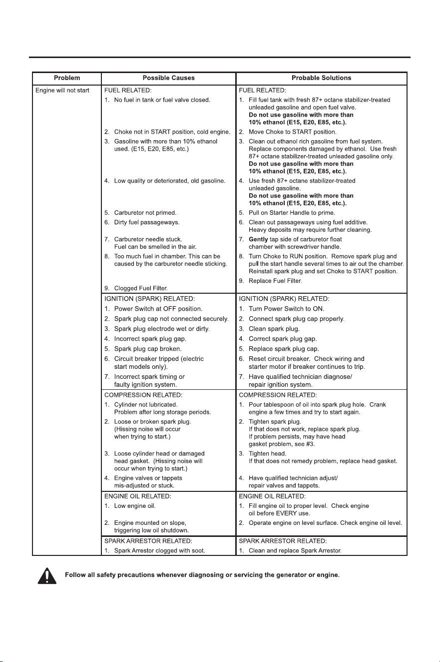
TROUBLESHOOTING
The table is a general troubleshooting method. If the fault is inconsistent with the table or the fault cannot be resolved,
contact the distributor.
- 32 -
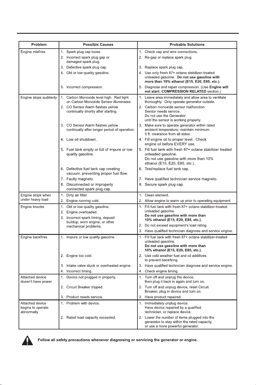
TROUBLESHOOTING
The table is a general troubleshooting method. If the fault is inconsistent with the table or the fault cannot be resolved,
contact the distributor.

- 33 -
TECHNICAL PARAMETERS
Engine Model
Engine Type
Displacement (cc)
Gas Distribution Mode
Cooling Mode
Rated Speed (RPM)
Starting Method
Fuel Type
Lubricating Oil Capacity (gal)
Lubricating Oil Model
Forced Cooling Wind
Gasoline / Propane(LPG) / Natural Gas(NG)
Rated Power Factor
Phase Number
Overall Dimension (in.)
Net Weight (lb.)
OHV
3800
SAE 10W/30
0.2(0.8L)
1
Single Phase
Stroke × Bore (mm)
4-stroke
518 (235kg)
Recoil Start / Electrical Start / Remote Start
312
80×62
180F/P-GS
47.8×40.7×25(1214×1034×633mm)
Valve Clearance
Input valve: 0.10~0.15 mm, Output valve: 0.15~0.20 mm
Noise dB (at 7m)(25% load)
63
Item
GM14000i-HSB
Rated Power (kW)
Max. Power (kW)
13(GAS.)/11.5(LPG)/10(NG)
14(GAS.)/12.5(LPG)/11(NG)
Rated Voltage (V)
Rated Frequency (Hz)
120/240
60

- 34 -
In production management, based on orderly, efficient, scientific principles. trying to do as
better as possible in product design, development, production, inspection, etc. to make our
production can keep orderly. And will continue to make improvement to make sure that
keep the competitiveness.
Welcome friends at home and abroad to visit and guide, work together to create
brilliant.
Phone
866-960-2920
service@genmaxpower.com
Http://www.genmaxpower.com
E-mail
You
Tube
f
+
R
Facebook Linkedin YouTube
ADD: 301 Doubleday Ave Ontario CA 91761