INVERTER GENERATOR
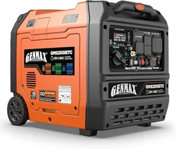
USER'S MANUAL
R
GENMAX GENERATOR
This manual contains important information regarding safety. Operation,
maintenance and storage of this product. Before use, read carefully and
understand all cautions, warnings, instructions and product labels. Failure to do
so could result in serious personal injury and/or property damage.
WARNING: SAVE THIS MANUAL FOR FUTURE REFERENCE
GM10500iETC
TRI-FUEL
TRI-FUEL INVERTER GENERATOR
1
UNPACKING
Always have assistance when lifting
the generator. The generator is heavy;
lifting it could cause bodily harm.
Avoid cutting on or near staples to
prevent personal injury.
Tools required - box cutter or similar device.
1. Carefully cut the packing tape on top of the carton.
2. Remove socket wrench, and oil funnel and save for
later.
3. Carefully cut two sides of the carton to remove the
generator.
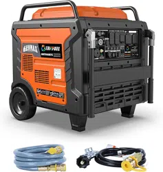
WHAT COMES IN THE BOX
Spark Plug Socket Wrench (1)
Dual-Purpose Screwdriver (1)
Owner Manual (1)
Warranty Information (1)
Funnel (1)
LPG Hose (1)
NG Hose (1)
NG Quick Connector (1)
Battery Charger (1)
ATS Cable (1)
Rain Cover (1)
Engine Oil (1)
DISCLAIMERS:
All information, illustrations and specifications in this manual are based on the latest information available at the
time of publishing. The illustrations used in this manual are intended as representative reference views only.
Moreover, because of our continuous product improvement policy, we may modify information, illustrations and/or
specifications to explain and/or exemplify a product, service or maintenance improvement. We reserve the right to
make any change at any time without notice. Some images may vary depending upon which model is shown.
ALL RIGHTS RESERVED:
No part of this publication may be reproduced or used in any form by any means - graphic, electronic or
mechanical, including photocopying, recording, taping or information storage and retrieval systems - without the
written permission of CHONGQING DINKING POWER MACHINERY CO., LTD
This manual contains important instructions for operating this inverter generator. For your
safety and the safety of others, be sure to read this manual thoroughly before operating the
generator. Failure to properly follow all instructions and precautions can cause you and others
to be seriously hurt or killed.

2
DESCRIPTION OF FITTINGS
Spark Plug Socket Wrench
Used in spark plug maintenance,
inspection, and installation.
Phillips and slot blade
screwdriver used for generator
maintenance.
Dual-Purpose Screwdriver Funnel
It's used to oil the generator.
LPG Hose
1500 mm
Hose length
1.312"-5ACME
Inside Diameter
∅20.2
Inside Diameter
∅35
Outside Diameter
Quick Plug Joint
LPG Hose
Pressure 1psi
First Stage Reducing Valve
Gas Cylinder Joint
Protective Cover
Connect the LPG tank to transmit LPG fuel to the
generator.
Battery Charger
Used to charge the battery
when in storage.
Remote Control Key
Used to remotely start and stop
the generator.
Rain Cover
Give the generator better
protection, water resistance,
scratch resistance.
Engine Oil
Be sure to add oil before starting
the generator.
NG Quick Connector
Protective Cover
∅20.2
Inside Diameter
∅35
Outside Diameter
Quick Plug Joint
NPT 1/2
Inside Diameter
Used to change a natural gas pipeline interface.
3
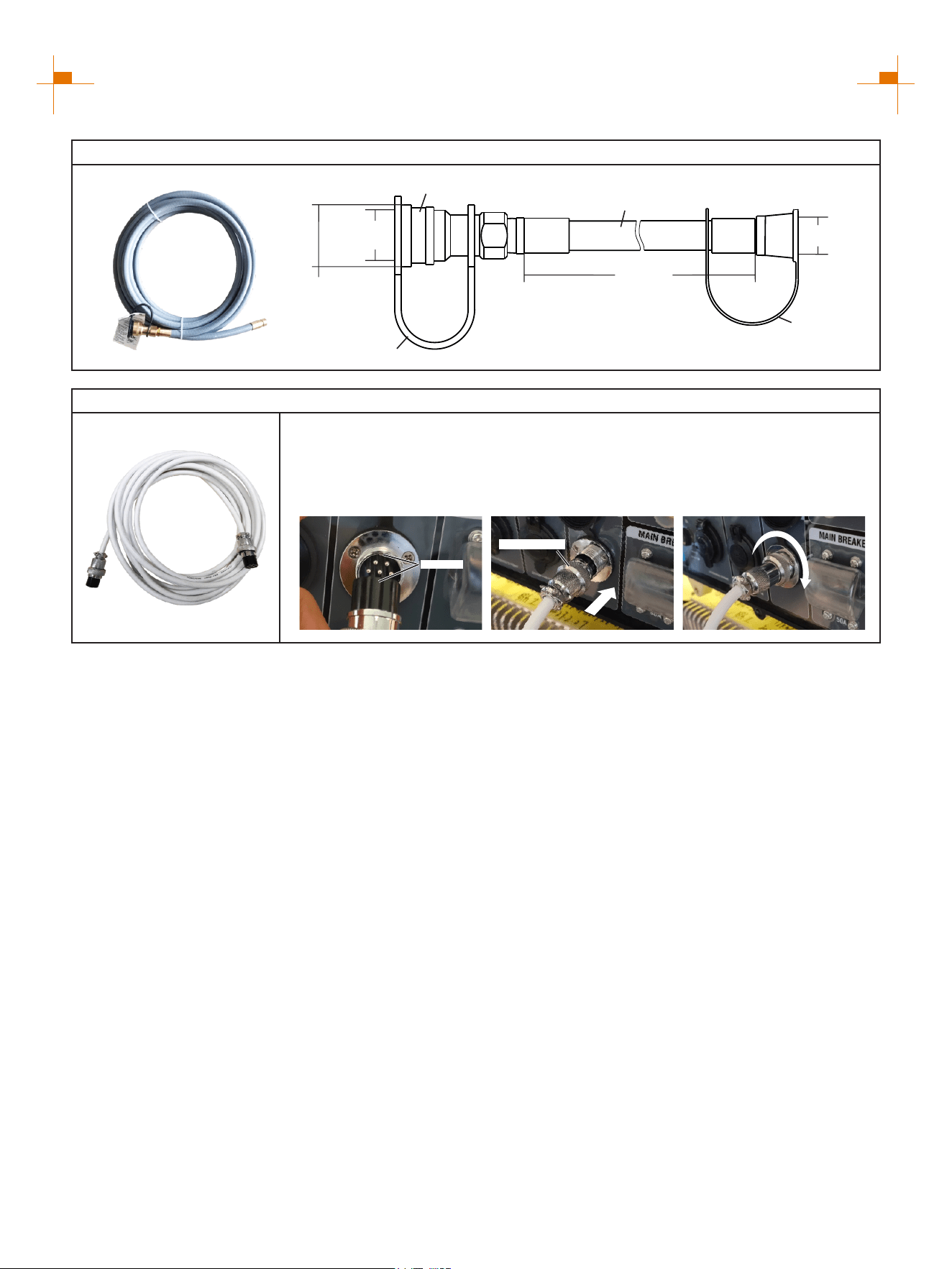
NG Hose
1500 mm
Hose length
Protective Cover
Protective Cover
NG Hose
Pressure 0.5psi
∅19
Inside Diameter
∅20.2
Inside Diameter
∅35
Outside Diameter
Quick Plug Joint
ATS Cable
Card Slot
Fastening Ring
Connect the ATS Cable
1. Align the groove on the ATS connector with the convex block of the ATS
socket and insert the cable into the socket.
2. Tighten the fastening ring.
Connect the natural gas
pipeline to transmit NG fuel to
the generator.
Note: Actual tools may differ in appearance or design from image shown.
4
LIMITED WARRANTY
1. DURATION : One (1) year from the date of purchase by the original purchaser ( retail customer ) on products used
solely for consumer applications; if a product is used for business, commercial, or industrial applications, the warranty
per iod will be limited to ninety (90) days from the date of purchase.
2. WHO GIVES THIS WARRANTY (WARRANTOR):
CHONGQING DINKING POWER MACHINERY CO., LTD
3. WHO RECEIVES THIS WARRANTY(PURCHASER):The original purchaser (other than for purposes of resale) of
the Genmax's inverter.
4. WHAT PRODUCTS ARE COVERED BY THIS WARRANTY: Any portable generator supplied or manufactured by
Warrantor.
5. WHAT IS COVERED UNDER THIS WARRANTY: Substantial defects on material and workmanship which occur
within the duration of the warranty period.
6. WHAT IS NOT COVERED UNDER THIS WARRANTY:
A. Transportation changes for sending the product to Warrantor or its authorized service representative for warranty
service, or for shipping repaired or replacement products back to the customer; these charges must be borne by the
customer.
B. Damages caused by abuse, accident, shipping, misuse, overloading, modification, and the effects of corrosion,
erosion and normal wear and tear.
C. Warranty is voided if the customer fails to install, maintain and operate the product in accordance with the
instructions and recommendations set forth in the owner's manual(s), or if the product is used as rental equipment.
D. Pre-delivery service, i.e. assembly, oil or lubricants, and adjustment.
E. Items or service that are normally required to maintain the product, i.e. lubricants and filters.
F. Warrantor will not pay for repairs or adjustments to the product, or for any costs or labour, performed without
Warrantor's prior authorization.
EXCLUSIONS AND LIMITATIONS : Warrantor makes no other warranty of any kind, express or implied. Implied
warranties, including warranties of merchantability and of fitness for a particular purpose, are hereby disclaimed. This
warranty service described above is the exclusive remedy under this warranty; liability for incidental and consequential
damages is excluded to the extent permitted by law.
7. RESPONSIBILITIES OF PURCHASER UNDER THIS WARRANTY:
A. The purchaser must provide dated proof of purchase and must notify Warrantor within the warranty period.
B. Deliver or ship the serviced generator or component to the nearest Warrantor's authorized service representative.
Freight costs, if any, must be borne by the purchaser.
8. HAVE QUESTIONS?
Email: service@genmaxpower.com Phone: 866-960-2920
Model Number: _____________________________________
Name: ___________________________________________
Serial Number: ______________________________________
Street Address: ___________________________________
Date Purchased: ____________________________________
Purchased From: ____________________________________
City, State, ZIP: ____________________________________
Country: __________________________________________
Phone Number: ___________________________________
E-Mail: ___________________________________________
WARRANTY CARD
R

5
TABLE OF CONTENTS
LIMITED WARRANTY
4
SAFETY WARNING
6
SAFETY INSTRUCTIONS
7
NAMES OF COMPONENTS
9
CONTROL FUNCTIONS
10
PREPARATIONS
14
1.Fuel...........................................................................................................................................14
2.Oil.............................................................................................................................................14
3.Pre-operation Inspection.........................................................................................................15
STARTING UP THE GENERATOR
16
SHUTTING DOWN THE GENERATOR
20
USING THE GENERATOR
21
1.Service Environment of the Generator.......................................................................................21
2.Generator Wiring........................................................................................................................21
3.Generator Grounding.................................................................................................................22
4.Changing the Neutral Point........................................................................................................23
5.Battery Charging........................................................................................................................23
SERVICE AND MAINTENANCE
24
1.Spark Plug Inspection..............................................................................................................25
2.Adjustment of the Carburetor..................................................................................................26
3.Replacement of Oil....................................................................................................................26
4.Oil Filter......................................................................................................................................27
5.Air Filter......................................................................................................................................27
6.Fuel Filter Screen......................................................................................................................28
STORAGE AND TRANSPORT
29
1.Generator Storage.....................................................................................................................29
2.Generator Transport..................................................................................................................30
TROUBLESHOOTING
31
TECHNICAL PARAMETERS
33
CIRCUIT DIAGRAM
34
CHOOSING A GENERATOR
35
6
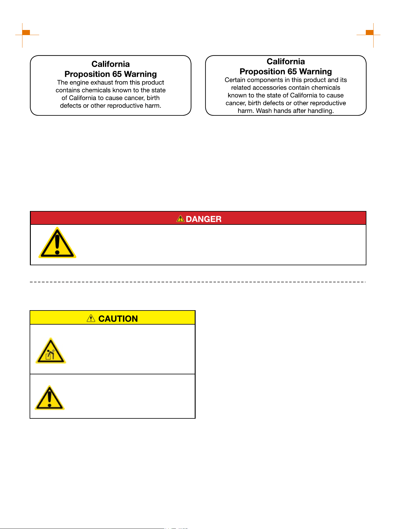
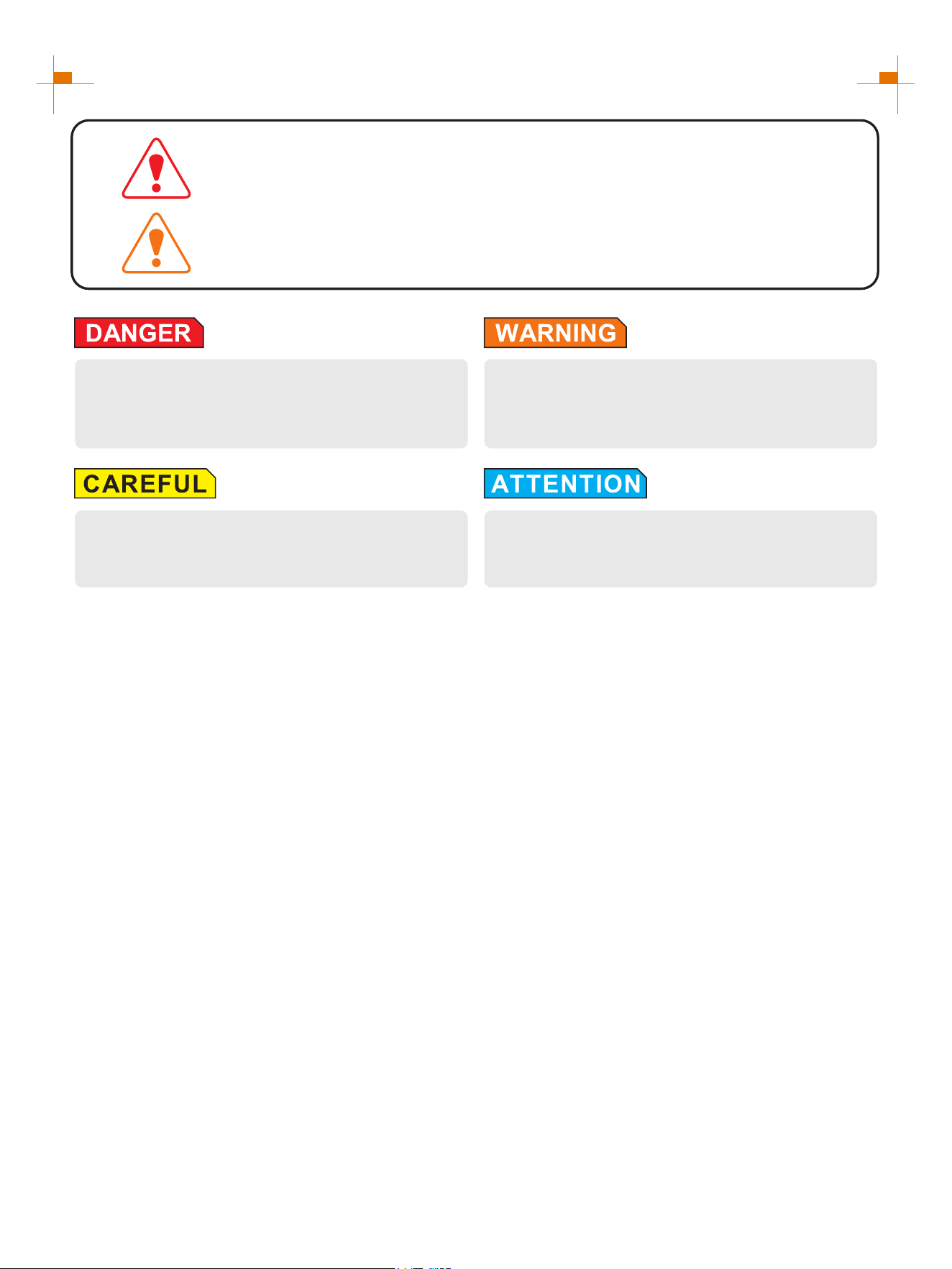
SAFETY WARNING
Personal and property safeties of you and others are very vital. Please read the Safety
Warning in the User's Manual and the decals of the generator set carefully.The Safety
Warning can alert you to those potential hazards that could harm you and others. In front
of each Safety Warning, there is one of four words "DANGER" "WARNING",
"ATTENTION", and "CAREFUL". Details are as follows:
Failure to follow the instruction will result in being
in peril of your life or extremely serious injury.
Failure to follow the instruction will result in being
in peril of your life or very serious injury.
Failure to follow the instruction will result in minor
injury.
Failure to follow the instruction will result in the
damage to your generator set and other properties.
For portable generators where the neutral is floating, the operator's manual shall include the following wording or
equivalent:
The portable generator stator winding is isolated from the frame and from the AC receptacle ground pin; and
Electrical devices that require a connection between one conductor pin and the grounded receptacle pin may not
function properly.
NEUTRAL FLOATING
CO DETECT technology monitors the accumulation of carbon monoxide (CO), a poisonous gas produced by
engine exhaust when the generator is running. If CO Sensor detects unsafe elevated levels of CO gas, it
automatically shuts off the engine. CO Sensor is not a substitute for an indoor carbon monoxide alarm or for safe
operation. DO NOT allow engine exhaust fumes to enter a confined area through windows, doors, vents or other
openings. Generators must ALWAYS be used outdoors, far away from occupied buildings with engine exhaust
pointed away from people and buildings. Meets the requirements of ANSI/PGMA G300-2018.
CO TECHNICAL WARNING
7
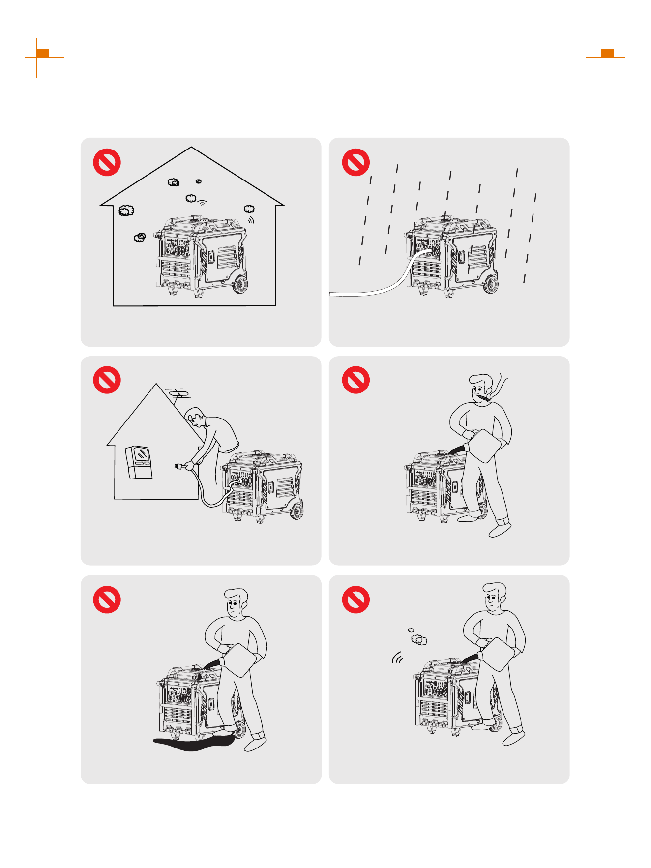
SAFETY INSTRUCTIONS
Before operating the generator, it will help you avoid accidents to read and understand the Manual and
familiarize yourself with the safe operation procedures of the generator.
Please do not use indoors
Please do not use in humid
environment
Please do not connect it to
household appliances directly
Please do not smoke when refueling
Please do not spill when refueling
Please shut down the generator
before refueling
8
SAFETY INSTRUCTIONS
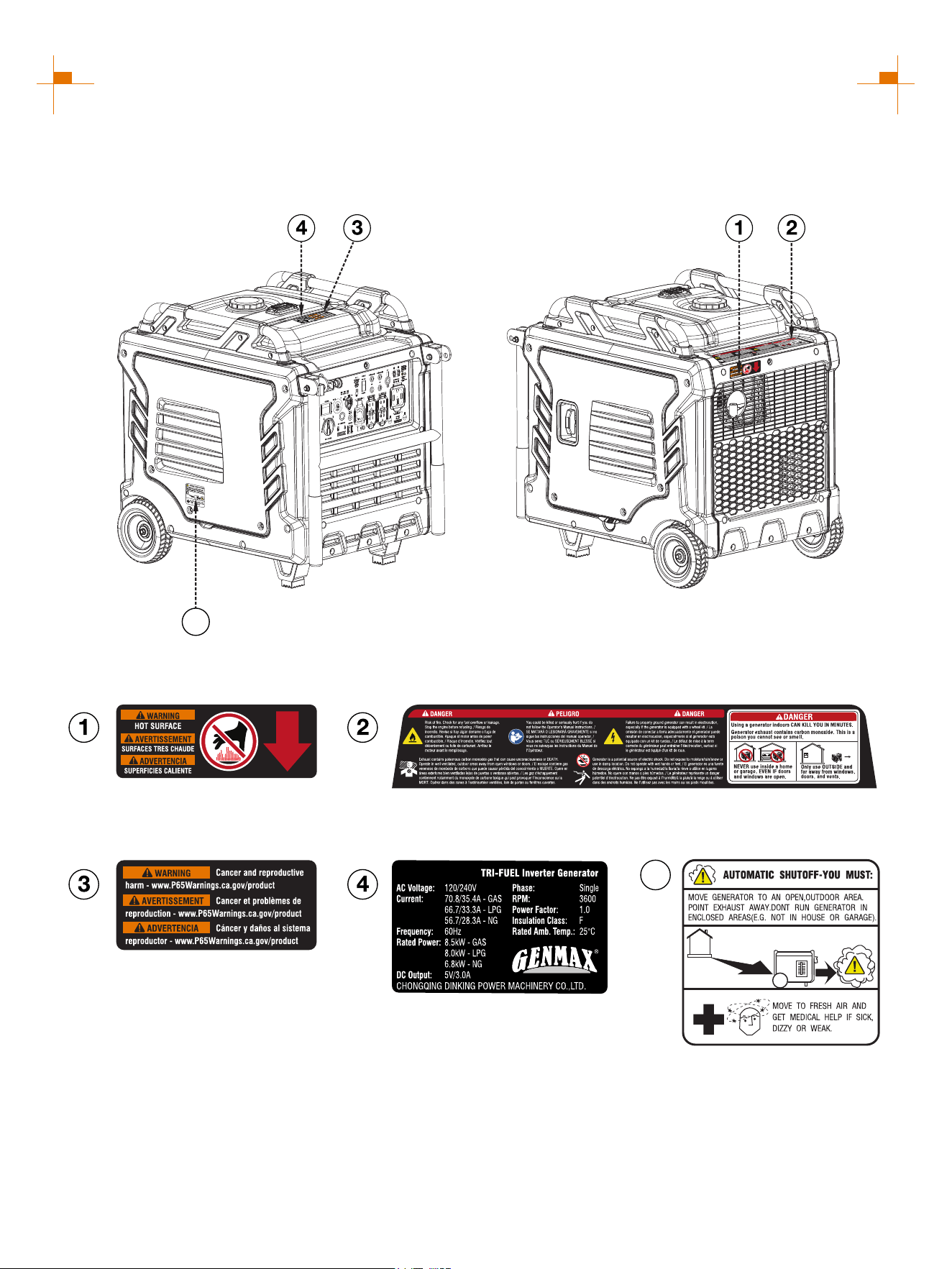
SAFETY LABELS AND DECALS
5
5
GM10500iETC
9
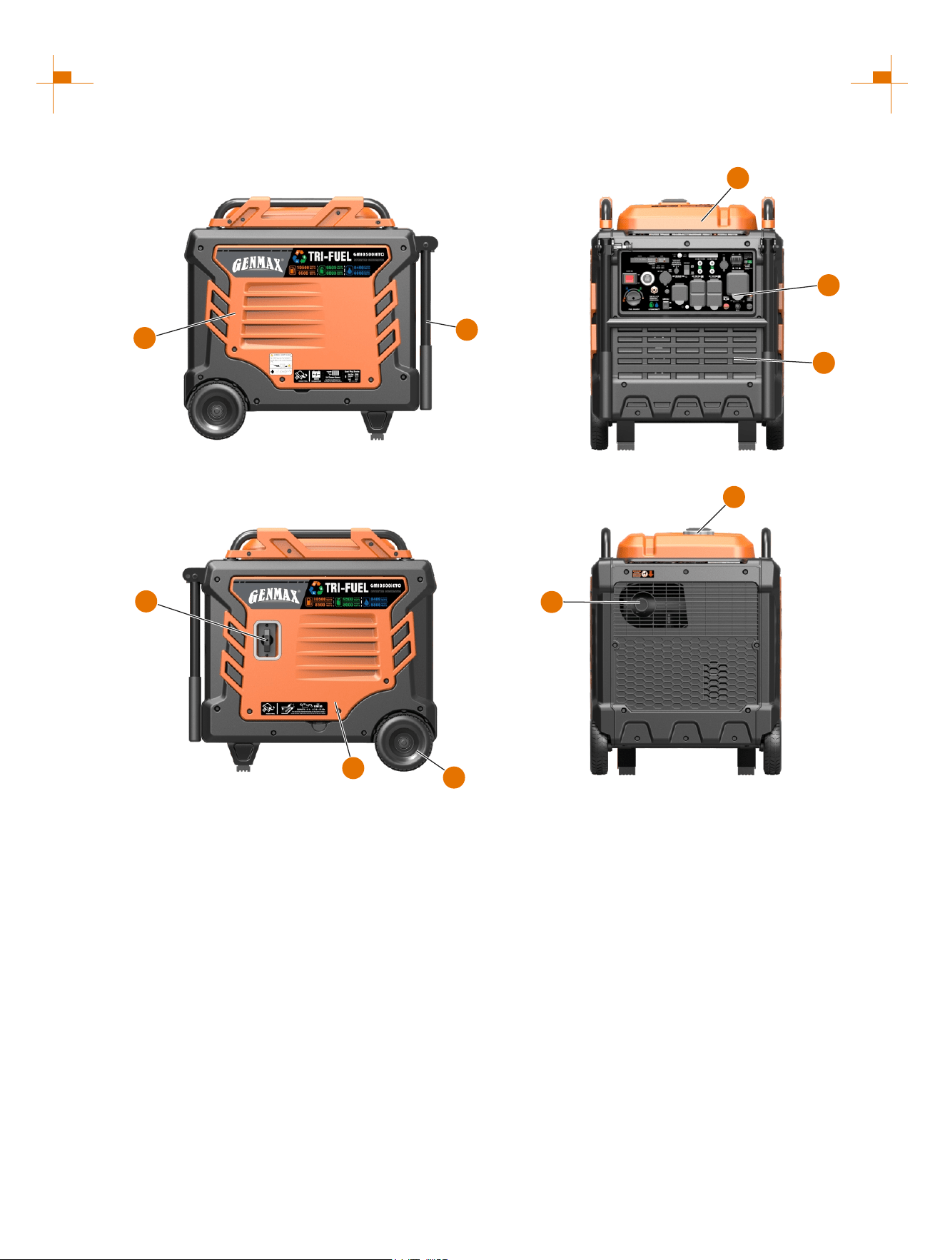
NAMES OF COMPONENTS
① Fuel Tank Cap: Open the fuel tank cap and fill with
proper amount of gasoline.
② Recoil Handle: Pull to start the engine.
③ Fuel Tank: Store the added gasoline.
④ Left Outer Cover: Unscrew the bolt, remove the
outer cover, connect the battery wire, maintain the air
filter and replace the spark plug.
⑤ Control Panel: Contains the reset breaker, outlets
and warning lights.
⑥ Engine Cooling Vents: Helps move airflow in unit
to regulate engine temperatures.
⑦ Right Outer Cover: Unscrew the bolts, remove the
outer cover, and add or change the oil.
⑧ Muffler: Avoid contact until the engine is cooled
down. The spark arrestor prevents sparks from exiting
the muffler. It must be removed for servicing.
⑨ Wheel
⑩ Handrail
1
6
5
8
9
2
3
4
7
10
10
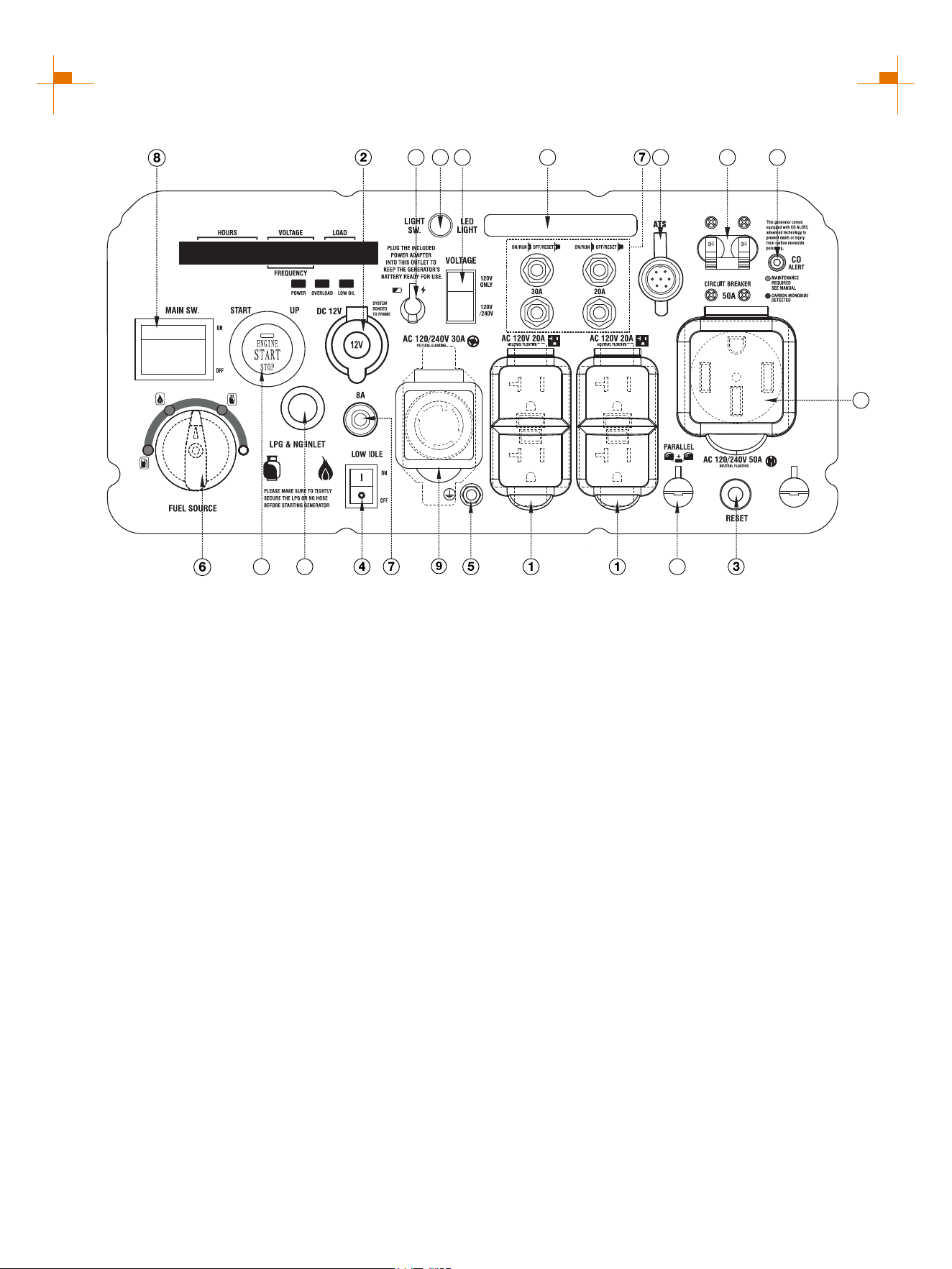
CONTROL FUNCTIONS
CONTROL PANEL FEATURES GM10500iETC
① 120V AC 20A 5-20R Outlet: The outlet is capable of
carrying a maximum of 20 amps.
② DC Cigarette Lighter Outlet: 12V DC 8.3A.
③ Reset: generator If the is overloaded, the reset breaker
will trip. The engine will continue to run, but there will be no
output from the . Unplug the devices and reduce generator
the load. Push in the reset breaker to reset it.
④ Low Idle: When turned to the ON position, the engine will
sense the load needed and run at a slower RPM to save fuel.
⑤ Ground Terminal: The ground terminal is used to
externally ground the .generator
⑥ Fuel Source Switch: Choice of fuel source.
⑦ AC Breaker: If the inverter is overloaded, the reset
breaker will trip to block current.
⑧ Main Switch: Manage battery power and shutdown. Tip: If
you do not use the generator for more than 7 days (168
hours), please press the main switch to the "OFF" position,
which can prevent the battery from running out.
⑨ 120/240V AC 30A L14-30R Outlet: The outlet is capable
of carrying a maximum of 30 amps.
⑩ CO Alarm: Shuts down the engine in the event of CO
buildup.
⑪ LPG Inlet: Connects the LPG inlet to the LPG
hose/regulator.
⑫ One Push Start: Press this button, the engine can start
and stop.
⑬ Voltage Switch: Switch between 120V and 240V voltage
as required.
⑭ Receptacle can supply 120/240V AC 50A 14-50R Outlet:
a maximum of 50 Amps.
⑮ To increase AC power output, the Parallel Connectors:
connector sockets are used to connect the two same type
generators with special parallel cable GM9000PK sold by
GENMAX. The connector sockets is only used to connect two
inverter generators. They can not used for AC power output.
The special parallel cable GM9000PK shall be purchased
separately, and they shall be approved by certification body.
⑯ Circuit Breaker: A circuit breaker interrupts the current
when the whole circuit is overloaded.
⑰ ATS Interface: For connecting to ATS control box.
⑱ Battery Charging Port: Charge the generator battery.
⑲ Light Switch: Press first to turn on the LED light and
second to turn off the LED light.
⑳ LED Light: 1. The LED light can be used normally when
the generator is running, and the LED light cannot be used
when the generator shuts down.
2. If the LED light is not turned off, press the one-key start
button (or remote control key) to stop the generator while the
main switch is not turned off, the LED light will automatically
turn off after 30 seconds.
3. Press the one-key start button (or remote control key) to
stop the generator and also turned off the main switch, the
LED light will go out immediately.
12 11
14
15
13 10161718 19 20
11
CONTROL FUNCTIONS
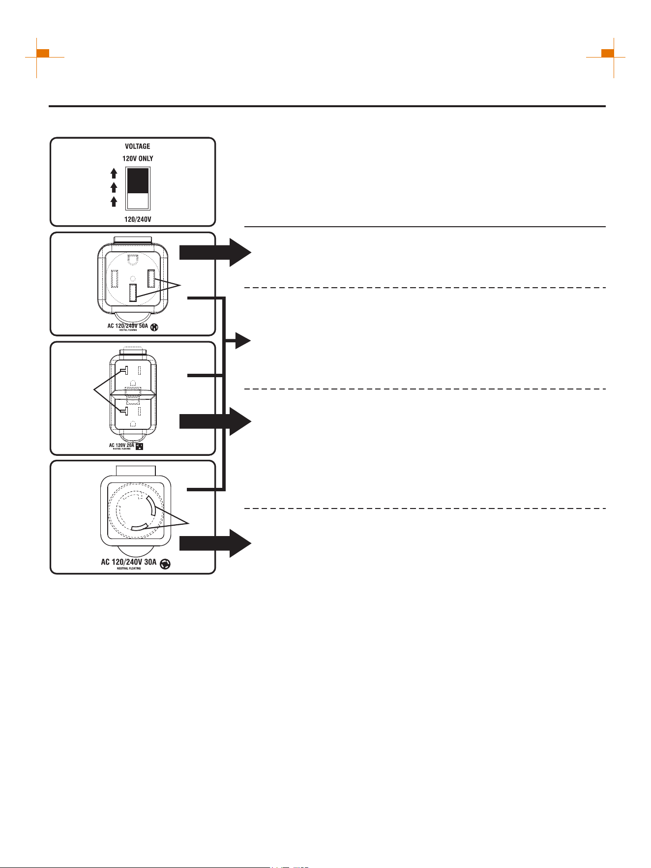
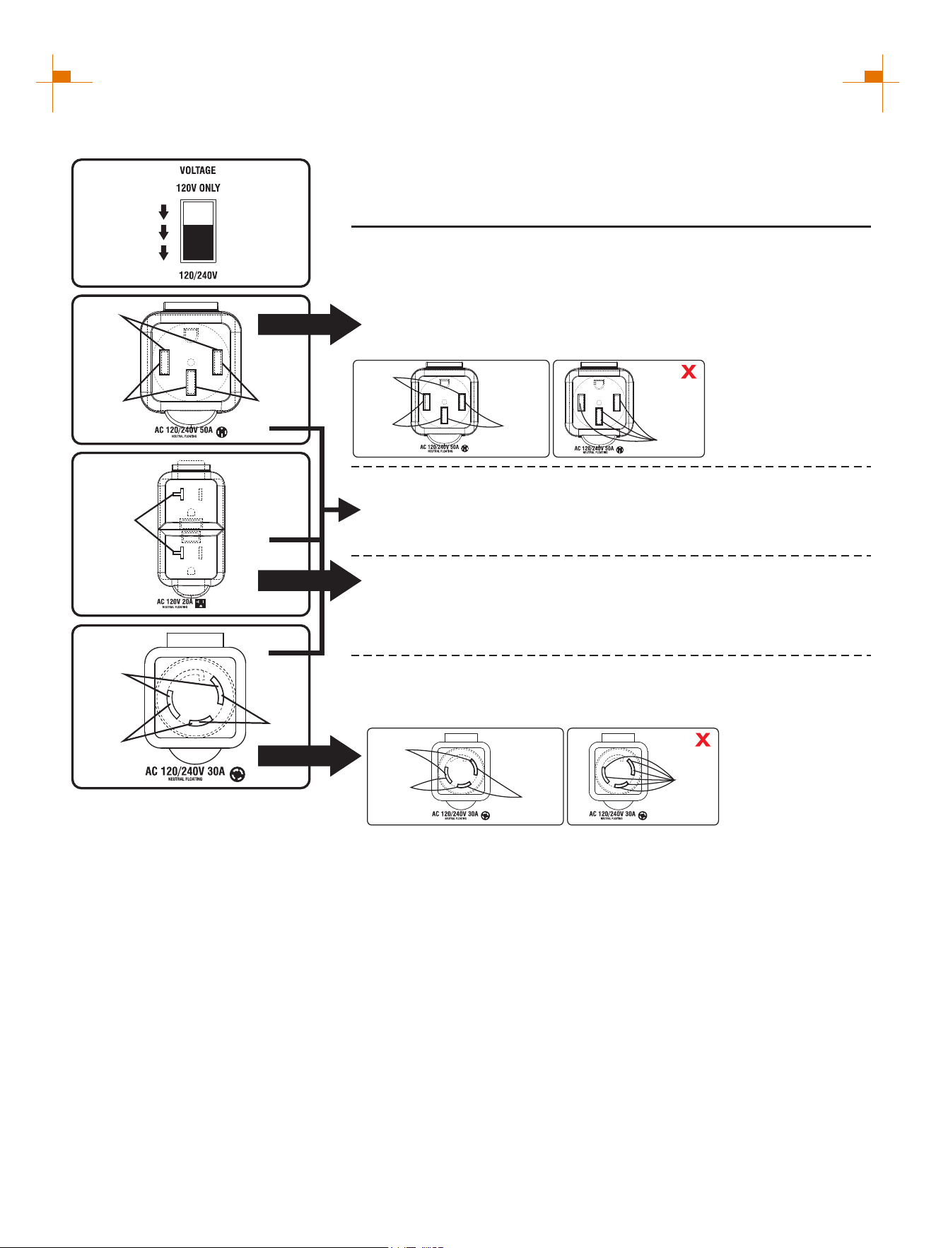
OUTPUT DESCRIPTION OF THE AC SOCKET
When the voltage selector switch is set to 120V ONLY
The voltage selector switch is set to 120V ONLY.
Output voltage can only be 120V and current 50A.
120V(Voltage)×50A(Current)=6000W(Output Power)
Single socket output
Single socket output
Output voltage 120V current 20A.
120V(Voltage)×20A(Current)=2400W(Output Power)
ATTENTION: The total power output of the socket must not exceed the
rated power of the generator.
A
Bx2
120V
120V
120V
Output voltage can only be 120V and current 30A.
120V(Voltage)×30A(Current)=3600W(Output Power)
Single socket output
C
12
CONTROL FUNCTIONS
The voltage selector switch is set to 120/240V.
The voltage is 120/240V and two generators can be connected in
parallel.
The output voltage is 120/240V, and the current is only 35.4A without
parallel connection.
120V socket hole: 120V(Voltage)×35.4A(Current)=4248W(Output Power)
240V socket hole: 240V(Voltage)×35.4A(Current)=8500W(Output Power)
When two generators are connected in parallel, the socket can output
240V voltage at 50A current:
240V(Voltage)×50A(Current)=12000W(Output Power)
Single socket output
Single socket output
Output voltage 120V current 20A.
120V(Voltage)×20A(Current)=2400W(Output Power)
A
Bx2
120V
120V
240V
120V
C load
B load
A load
OK
①
②
③
①
②&③
ATTENTION: ①②③ can
output at the same time, but
the total power output of the
socket can not exceed the
rated power of the generator,
can not be connected to the
same load.
A load
When the voltage selector switch is set to 120/240V (Suitable for parallel)
Single socket output
C
ATTENTION: The total power output of the socket must not exceed the
rated power of the generator.
120V
120V
240V
①
②
③
Output voltage 120V current 30A.
120V socket hole: 120V(Voltage)×30A(Current)=3600W(Output Power)
240V socket hole: 240V(Voltage)×30A(Current)=7200W(Output Power)
ATTENTION: ①②③ can output at the same time, but the total power output
of the socket can not exceed the rated power of the generator, can not be
connected to the same load.
B load
A load
OK
③
①&②
A load
C load
13
CONTROL FUNCTIONS
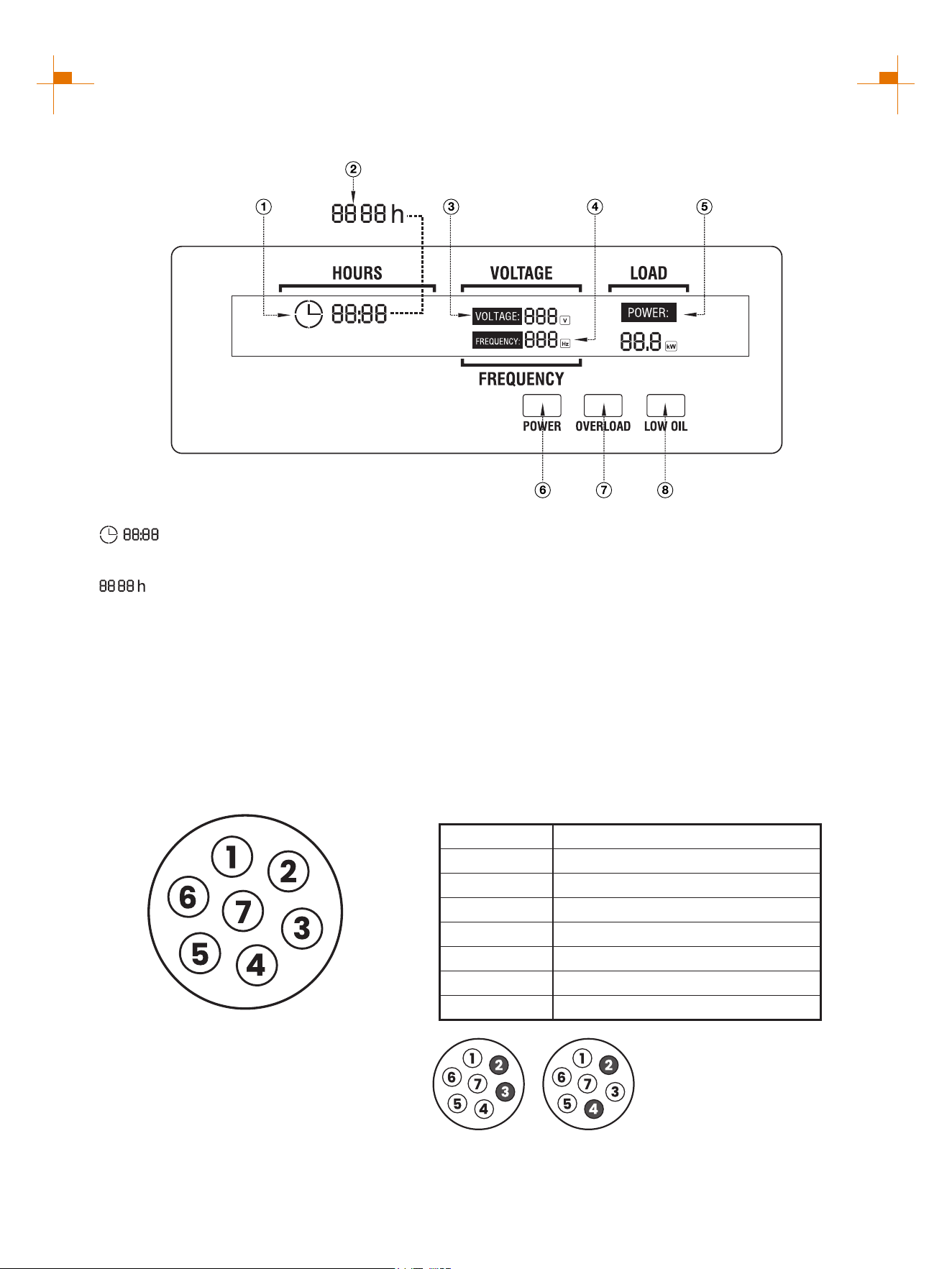
DIGITAL DISPLAY CENTER
① : Represents single run time, goes from 0 at
each startup.
② : Represents total operation time of the
generator.(Tip: The total operation time shall start to
accumulate after the generator runs for one hour. It will not
be displayed when the generator runs for less than one
hour. The total operation time shall be accumulated by
hours.) The two factors ① and ② are displayed alternately
every 8 seconds.
③ VOLTAGE: Voltage display: 120V and 240V switch every
16 seconds.
④ FREQUENCY: Frequency display.
⑤ LOAD: Load power display.
⑥ POWER: Green light means normal operation.
⑦ OVERLOAD: Red light means the machine overload.
⑧ LOW OIL: Red light means the amount of oil is too low.
WORKING MODE OF THE ATS SOCKET
Number
Connection Function
1
2
3
4
5
6
7
Battery Charge +12V
Ground
Engine Start
Emergency Stop
Not Connected
Engine Running
Not Connected
2/3 are for start and stop the
generator 2/4 are for
emergency shutdown the
generator.
ATS SOCKET
14
PREPARATIONS
Fuel
1
DANGER
• Fuel is flammable and toxic, please read the Safety Instruction carefully before refueling;
• Do not fuel too full, otherwise fuel will spill after fuel tank is warmed;
• After refueling, confirm that the fuel tank cap has been tightened.
ATTENTION
• After refueling, dry gasoline residue with a clean and soft cloth in time to avoid damaging plastic
enclosure;
• Unleaded gasoline must be used, as leaded gasoline can seriously damage internal parts of the
generator;
Remove fuel tank cap, and add gasoline to red horizontal indicating line oil level.
Fuel tank capacity: 6.9gal (26L)
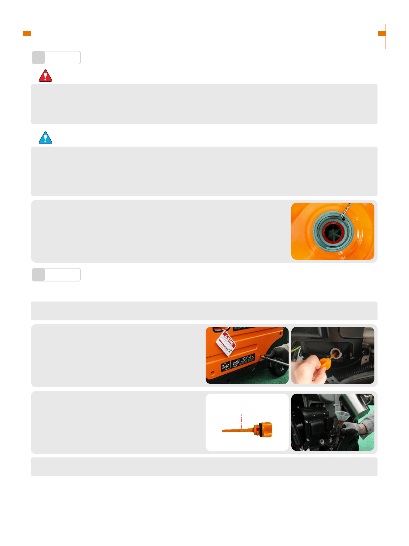
Oil
2
No oil is filled into this generator when being delivered. Do not start up the generator without filling sufficient oil.
Please place the generator onto a horizontal plane surface;
1.
Open the right exterior cover, unscrew oil
dipstick;
2.
Fill in 0.3gal(1.1L) oil (SAE 10W/30 oil is
recommended, of which the grade is API
standard Type SE or higher);
3.
Don't go over the scale
Cover the right panel.
4.
15
PREPARATIONS
Pre-use Inspection
3
WARNING
Even if the generator is not in service, its important component may suddenly fails. Before the
generator is started up, if any of following components is unable to work properly, please inspect
and repair carefully.
Tip: The condition of the generator shall be inspected before using every time.
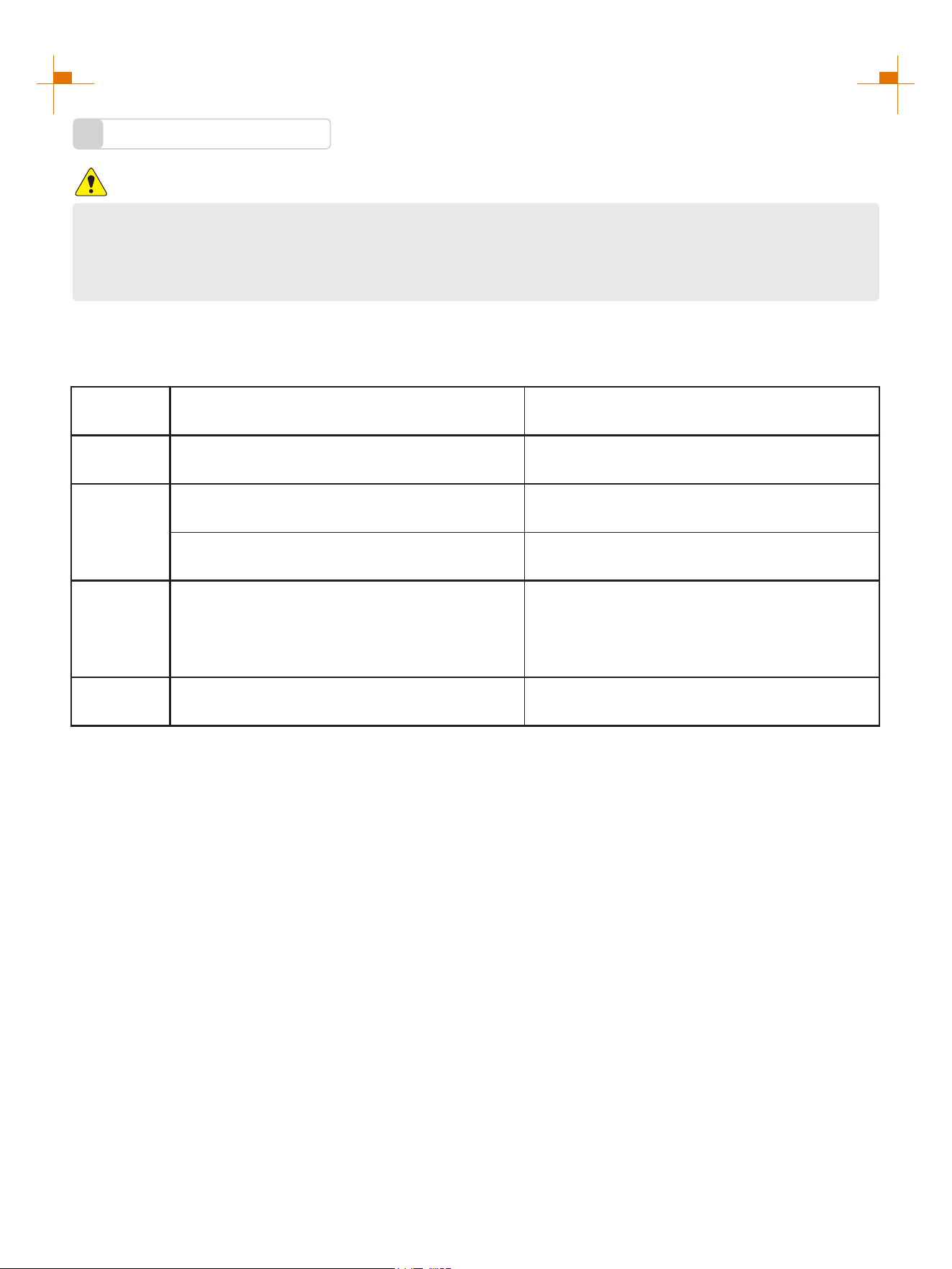
Pre-operation inspection
Project Possible Causes Probable Solutions
Fuel Check fuel level in fuel tank of the generator. Add fuel if necessary.
Oil
Check oil level of the generator. Add oil if necessary.
Check whether there is oil leaking.
Abnormal
conditions
during
operation
Check operating condition of the generator.
If there is any need, please do not hesitate to
consult your dealer.
Battery
Check whether the battery is full. See the “Battery Charging” page.
16
STARTING UP THE GENERATOR
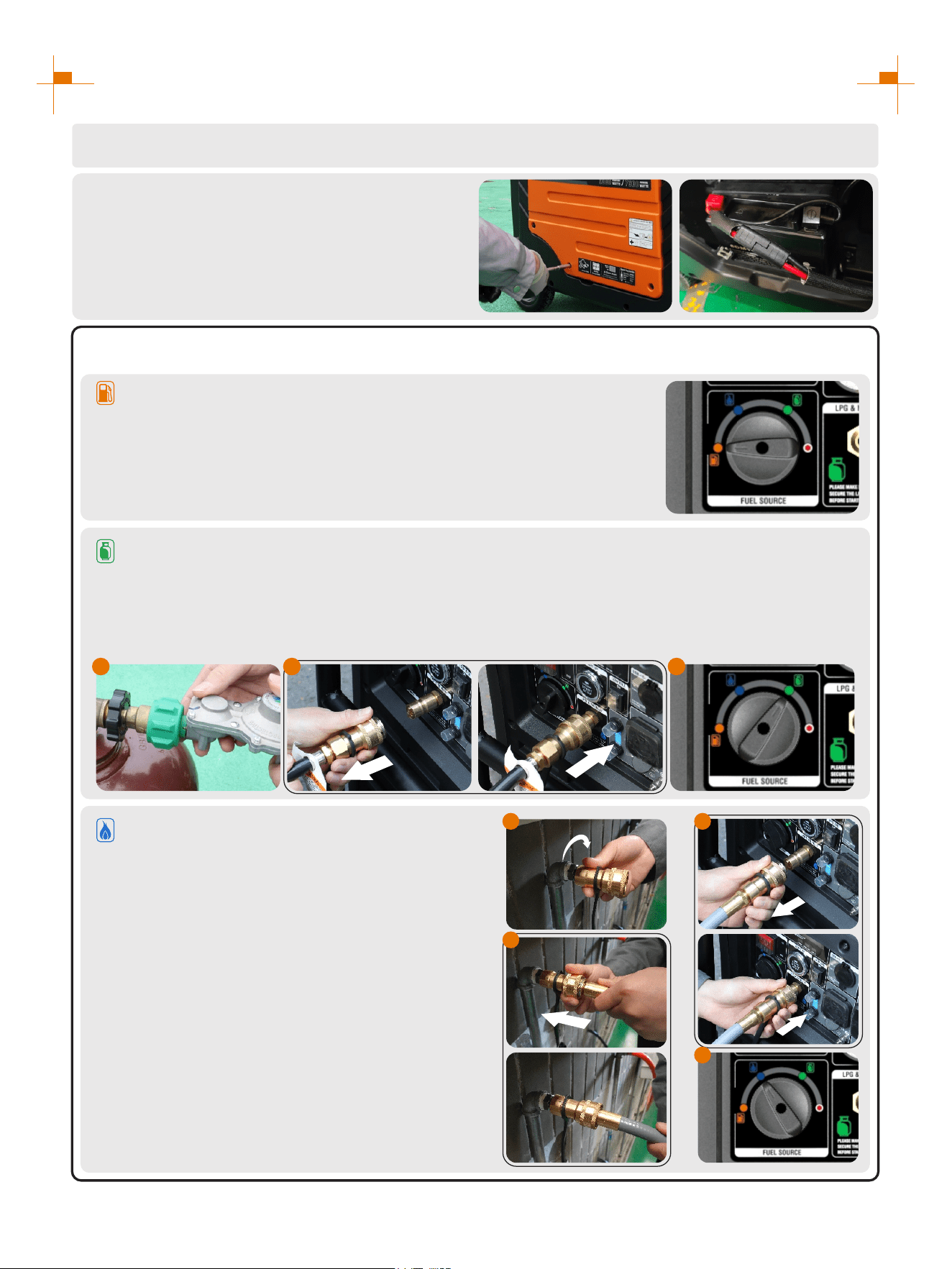
a. Gasoline: Turn the fuel source switch to gasoline.
3.
Remove the load from all output ends;
1.
Connect battery line before first use:
1. Remove the left panel cover;
2. Connect the positive and negative electrodes
of the battery.
Tip: Connect the same color wires together, do
not connect the wrong positive and negative wires.
2.
b. LPG:
1. Connect the LPG hose to the LPG tank;
2. Push back the quick connector sleeve of the LPG hose, insert the LPG/NG inlet, loosen the quick
connector sleeve, and make the sleeve clamp the LPG/NG inlet;
3. Turn the fuel source switch to LPG.
Select the Fuel:
c. NG:
1. Screw the gas pipe adapter onto the gas pipe;
2. Push the quick connector sleeve backward,
insert the NG hose, then loosen the quick
connector sleeve, and make the sleeve clamp
the hose joint;
3. Push back the quick connector sleeve of the
NG hose, insert it into the LPG/gas inlet, loosen
the quick connector sleeve, and make the sleeve
clamp the LPG/gas inlet;
4. Turn the fuel source switch to NG.
1 2 3
1
2
3
4

17
STARTING UP THE GENERATOR
Select Boot Mode:
a. Hand Starting: Pull the starting handle to start the generator.
b. One Button to Start: Press the one-click start button to start the generator.
c. Remote Start: Press the "START" button on the remote control to start the generator.
6.
Plug in after started.
7.
Remote Control Pairing
1. Long press the start button for more than 5 seconds until the button red indicator is on;
2. Press any key on the remote control;
3. The red indicator of the start button will blink two or three times and then turns off, Remote start pairing is
successful.
Tip: The remote control delivered with the generator has been paired successfully.
Press the LOW IDLE switch to "OFF";
4.
Press the main switch to "ON";
5.
a
b
c
1 2
3.1 3.2
18
STARTING UP THE GENERATOR
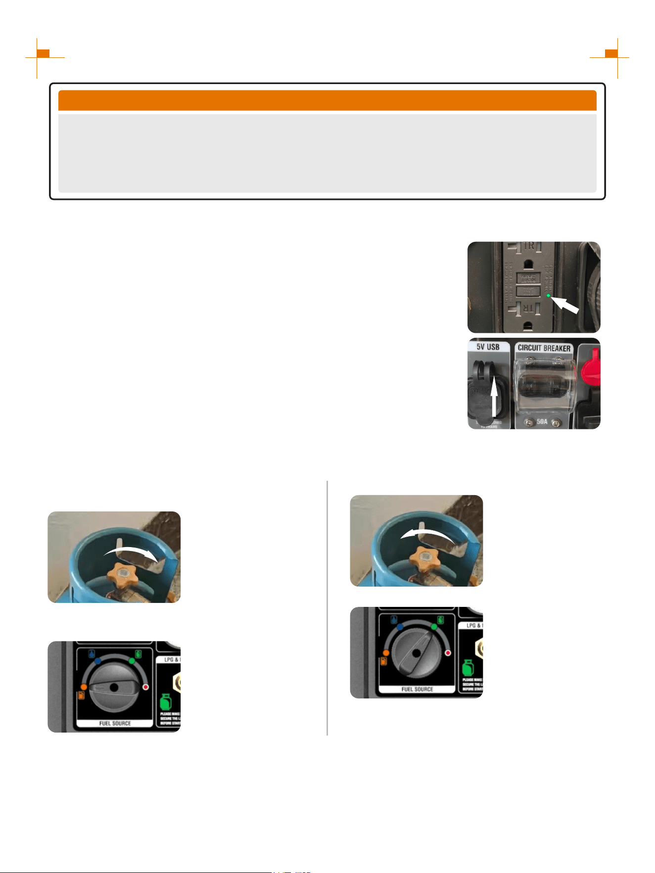
LPG tartup is difficult ?
When both gasoline and LPG(or NG) are present in the generator it is recommended to start the generator on
gasoline first, allow the engine to stabilize then switch to LPG(or NG).
1. Ensure the LPG (or NG) supply hose is securely
attached and Close the LPG (or NG) valve completely.
2. Fuel source rocker switch to “GASOLINE”.
3. Follow the startup steps to start the generator.
4. Open the LPG (or NG) valve completely.
5. Fuel source switch to “LPG (or NG)”.
OPEN
CLOSE
Electric start and remote start no response ?
1. Check whether the positive and negative electrodes of the battery are correctly connected.
2. Check whether the battery is charged.
3. Check whether the remote control is powered on.
(2) Check whether the circuit breaker switch is set to “ON”.
If the circuit breaker switch is set to ON and there is no output, press the heat
protection corresponding to the socket and use a multimeter to test whether the
socket has voltage.
ON
COMMON PROBLEMS WITH STARTING THE GENERATOR:
Start the generator to run normally without output ?
(1) Check whether the green light of the GFCI socket is on.
If the green light is not on, press the RESET button after the generator is started
to make the green light on.
Tip: When the generator is not started, the GFCI socket is in the protected state and
the "RESET" button cannot be pressed.
TIP
Remote Control Key Dormancy
When generator stops running for 5 days (120hours), while the main switch is not turned off, the remote
control key cannot be used to start the generator again. At this time, you need to turn off the main switch
and turn it on again, or press the one-key start button (or hand start) to start the generator, and the remote
control key will be reactivated.
19
STARTING UP THE GENERATOR
INVERTER PARALLEL KIT OPERATION
50A Parallel Kits
Round Connector (Black)
Ground Connectors (Ring)
Square Connector (Black)
Connectors(Red)
This parallel kit is intended to be used
only with GENMAX inverter generators.
Please read safety information below
before proceeding.
1. Make sure both engine switches are in the off position, and confirm the Low idle switches on
both generators are turned off.
2. Attach the ground terminal (green wire) from each end of the parallel cable to the
corresponding ground terminal on each generator. Connect and tighten the ground wire.
3. Connect the black and red parallel cable leads to the black parallel ports on each
corresponding inverters control panel. connect two red leads or two black leads DO NOT
into the same inverter. Pay attention: The white wire leave as it is, this just needed when
parallel two GM9000i.
4. Connect the black square connector to the square socket of the generator.
5. Start each generator and confirm that the green output indicator is illuminated on both.
Tip: When two generators are connected in parallel, the voltage selector switch must be placed
at 120/240V before starting.
6. If using Low idle mode, turn both Low idle switches on after the generators are started.
7. To shut down, turn off both generators and then remove the parallel cords.
Connectors (Red)
Round
Connector
(Black)
Ground Connectors
(Ring)
NOTICE: If high electrical loads are connected,
turn the Low idle switch to the OFF position to
reduce voltage changes. With the generators
running, make sure both green output indicator
lights are ON. If not ON, turn the generators off,
restart the generators, and make sure both
green output lights are ON.
Square Connector
(Black)

20
SHUTTING DOWN THE GENERATOR
Unplug the power cord;
1.
Select Stop Mode:
a. One Button to Start: Press the one-click start
button to turn off the generator.
b. Remote Start: Press the "STOP" button on
the remote control to turn off the generator.
2.
Press the main switch to "OFF";
3.
Set the fuel source switch to the off position.
4.
The above instructions for starting and stopping the generator are normal procedures. Users
must follow standard procedures to start, use and shut down the generator.
IMPORTANT NOTES
1. If the user directly turns off the generator with the main switch,
there may be a sound of muffler blasting, which is a normal
phenomenon under abnormal operation.
2. When the battery is not connected or the battery is out of charge, if
the user directly turns off the generator with the main switch, it may
be difficult or impossible to start the cold machine, which is a
normal phenomenon under abnormal operation.
a
b
21
USING THE GENERATOR
Service Environment of the Generator
1
• Applicable temperature: -5°C ~ 40°C;
• Applicable humidity: below 95%;
• Applicable altitude: regions below 1,500 m (It shall be used by reducing power in regions above 1,000 m).
Standard atmospheric condition
• Ambient temperature Tr: 298k (25°C)
• Relative air humidity Фr: 30%
• Absolute atmospheric pressure Pr: 100kPa
When actual environmental condition is inconsistent with the condition of output power of the generator
set:
• Every 5°C of increase in ambient temperature will reduce the power of generator by about 2%.
• Every 30% of increase in relative humidity of air will reduce the power of generator by about 1.5%.
• Every 300 m rising of ASL will reduce the power the generator by about 4.5%.
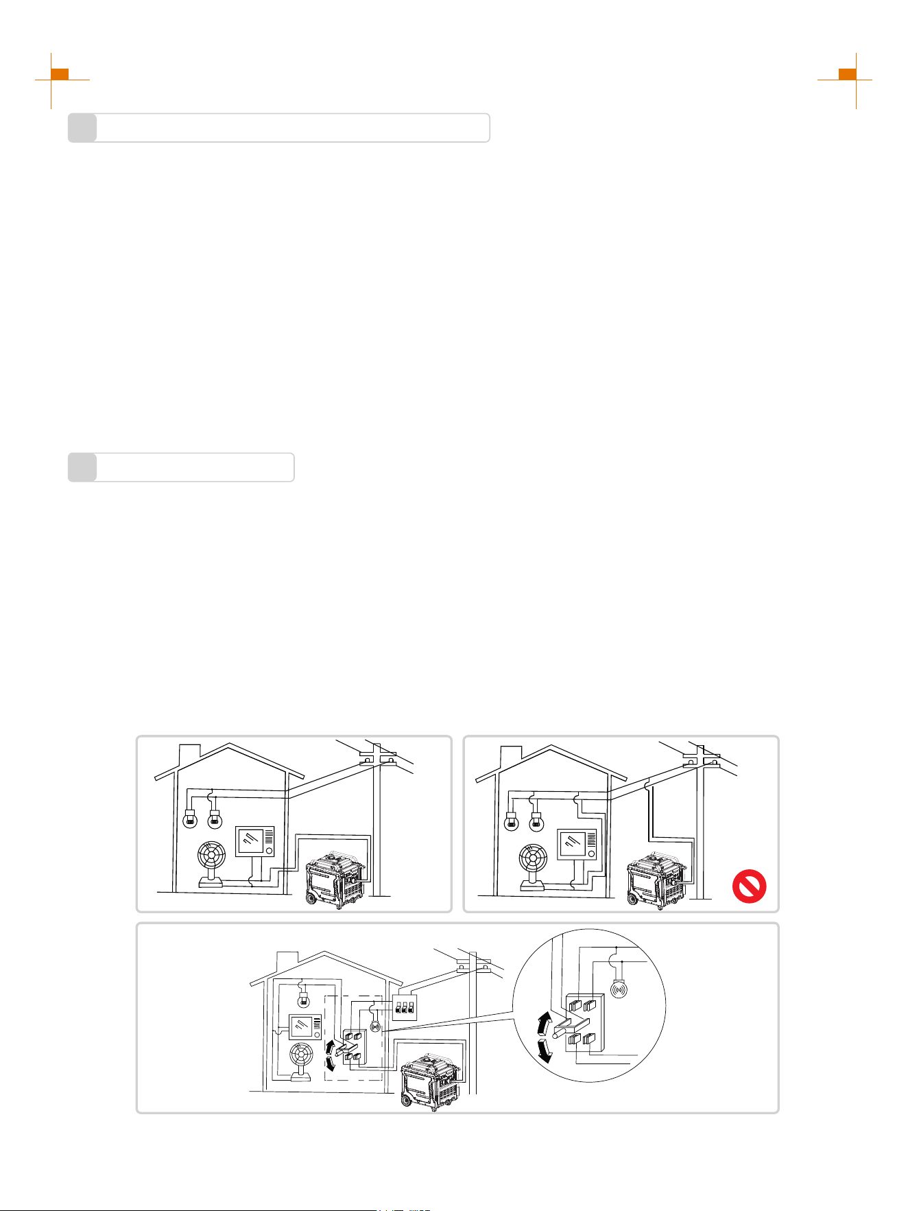
Generator Wiring
2
• When the generator is connected to household power source as a backup power supply, the connection shall be
carried out by a professional electrician or a person familiar with electricity.
• After connecting the load to the generator, check carefully whether electrical connection is safe and reliable.
Improper electrical connection may cause generator damage, burning or fire.
• Avoid connecting this generator to commercial power outlet.
• When extending the cable, be sure not to exceed its length.
① 60m cross-section area is 1.5mm²
② 100m cross-section area is 2.5mm²
• The appearance of extension cable shall be protected by a layer of tough and elastic rubber cover (IEC25) or
other substitutes.
OK
OK
22
USING THE GENERATOR
Connection of AC power
WARNING
All electrical equipment shall be disconnected before inserting the plug.
ATTENTION
• Make sure that all electrical equipment, including wires and plugs, are in good condition before
connecting to the generator;
• Make sure that all loads driven by the generator are within rated load range;
• Make sure that load current is within rated current range of rated socket.
Tip: Make sure that the generator set is grounded, and if electrical equipment requires
grounding, the generator set must be grounded.
① Start up the engine;
② Turn energy-saving switch to "ON";
③ Insert the plug into AC outlet;
④ Make sure that AC indicator is lit up;
⑤ Switch on electrical equipment.
Tip: Before increasing engine speed, energy-
saving switch must be switched to "OFF". If the
generator set supplies power to multi loads or
electrical equipment, start from large to small
according to the size of each electrical
equipment.
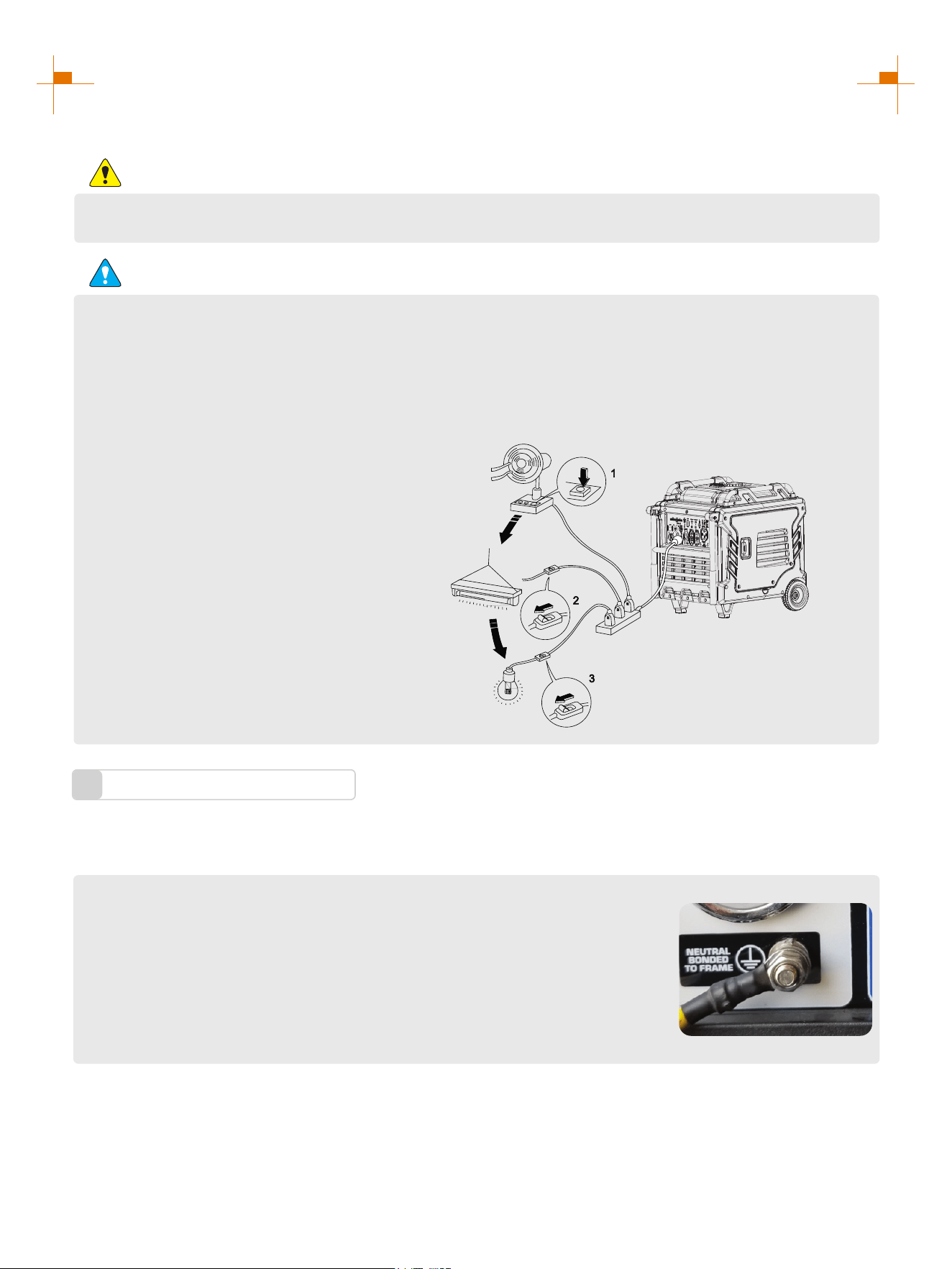
Generator Grounding
3
① Please use grounding wire with sufficient electrical energy capacity;
② Connect one end of grounding wire reliable to grounding bolt on control panel
of the generator set;
③ Insert grounding body (iron rod with a diameter of 5 ~ 10mm) 200mm below
into the earth and lead it out with conductor;
④ Connect the other end of the grounding wire reliable to the led wire of
grounding body.
In order to prevent any damage to the generator caused by electric shock or improper electrical application, it is
recommended that the generator is grounded with good conductor with insulating sheath.
Tip: How to change the grounding method please refer to the website: https://www.genmaxpower.com/page/faq
23
USING THE GENERATOR
Battery Charging
5
Connect the charger to the battery charging port on
the generator panel and connect the mains to
charge the battery.
The battery storage time is generally about 6 months. If the generator is not used for a long time, the battery will
run out of power. At this time, the battery should be charged. Replace the battery if it is damaged or fails to
charge.
Hand start charging: Start the generator by hand, and the battery will be charged automatically when the
generator runs.
Use an external power source for charging:
WARNING
Do not start the generator while charging with an external power supply. Keep batteries away from
fire sources. Keep the battery in a cool and dry place, away from direct sunlight. Keep batteries
away from children.
ATTENTION
1. Charge properly
Keeping battery properly charged and discharged can prolong battery life. Maintaining a power level of 10%-
90% in battery is beneficial for battery protection.
2. Choose the appropriate charging temperature
Battery charging temperature range: 0-45℃.
3. Avoid overcharging
Overcharging of battery must be avoided during the charging process. Overcharging of battery in any form will
lead to serious damage to battery performance and even explosion.
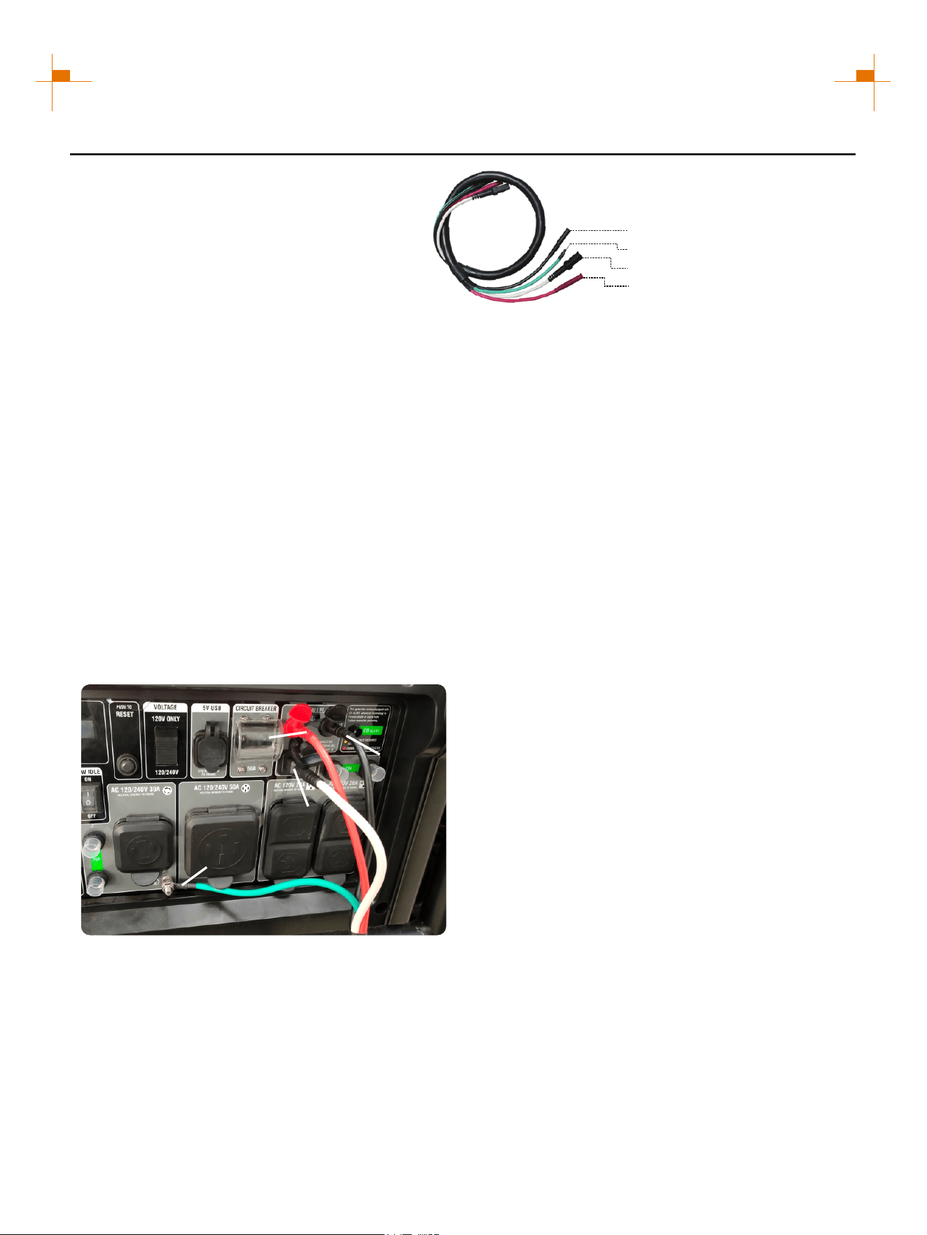
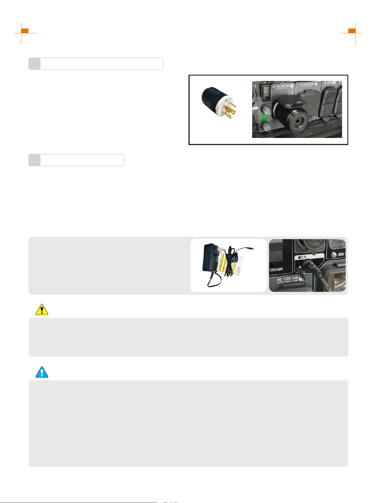
Changing the Neutral Point
4
This generator is "neutral floating" state, if you want to
change to a "neutral bonded" state, insert the Bonding
Plug into the output socket of the generator to change
the neutral floating to neutral bonded status.
Special Bonding Plug must be purchased
separately.
NEMA L14-30P
Bonding Plug
24
SERVICE AND MAINTENANCE
Good maintenance and service is the best guarantee for safe, economical and zero-failure operation. It also
contributes to environmental protection.
In order to keep the generator in good condition, you must inspect and maintain it regularly. The maintenance
schedule is as follows:
Maintenance cycle
Item
Each
First in 1 month
or 20 hours
Then every three
months or every
50 hours
100 hours per
year or use
Engine oil
Gearbox gear
Oil (if any)
Air cleaner
element
Settling cup (if any)
Spark plug
Spark eliminator
Idle speed
(if any)**
Valve clearance**
Fuel tank and
fuel filter***
Fuel line
Cylinder head,
piston
Displacement < 225cc, every 125 hours; displacement
capacity ≥ 225cc, every 250 hours.
Check-fill
Replace
Replace
Check oil
Inspection
Clean
Replace
Clean
Clean-adjust
Clean
Check-adjust
Check-adjust
Clean
Inspection
Remove
carbon
deposit**
Every two years (Please replace if necessary)
√
√ √
√
√ √
√
√
√
√
√*
√
√
√
√
* heseT items shall be replaced if necessary;
** heT se items shall be maintained by the dealer authorized by the Company, unless the
user has proper tools and maintenance ability.
ATTENTION
• If it often works under high temperature or high load, oil shall be changed every 25 hours;
• If it often works in dusty or harsh environment, air cleaner element shall be cleaned every 10 hours. If
necessary, the air cleaner element shall be replaced every 25 hours;
• It shall be maintained on spot-inspection cycle and time, whichever is earlier;
• If maintenance cycle time has elapsed, perform the maintenance as soon as possible as per the table
above.
25
SERVICE AND MAINTENANCE
WARNING
Please shut down the engine first before performing any maintenance. The engine shall be placed in a
horizontal position. In order to prevent the engine from starting up, separate spark plug cap shall be
separated from spark plug.
Do not use it indoors or use it in a tunnel, cave or other places ventilated poorly. Make sure that work area
is well ventilated. Exhaust gas from the engine contains toxic gases, carbon oxides, and the inhalation can
cause shock, loss of consciousness, and even death.
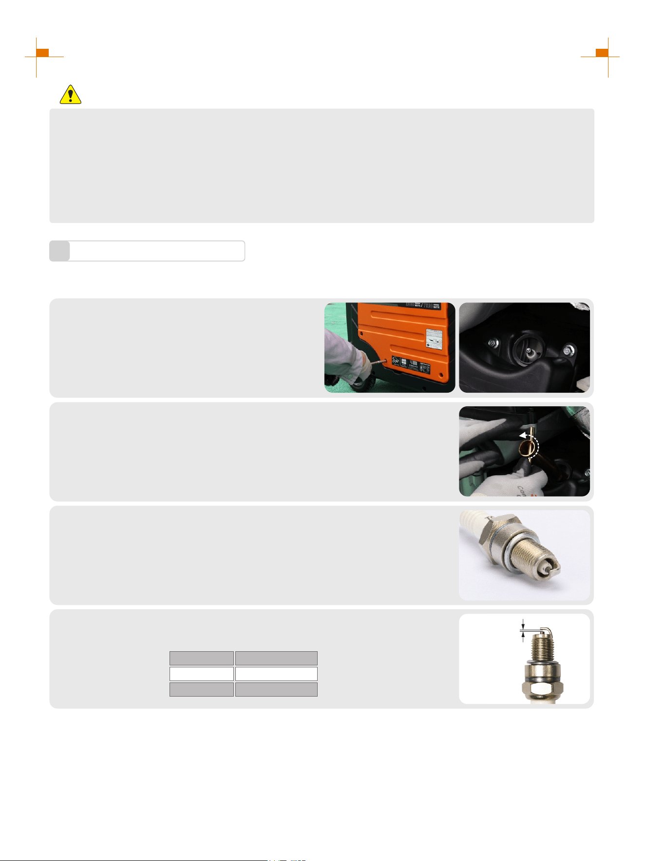
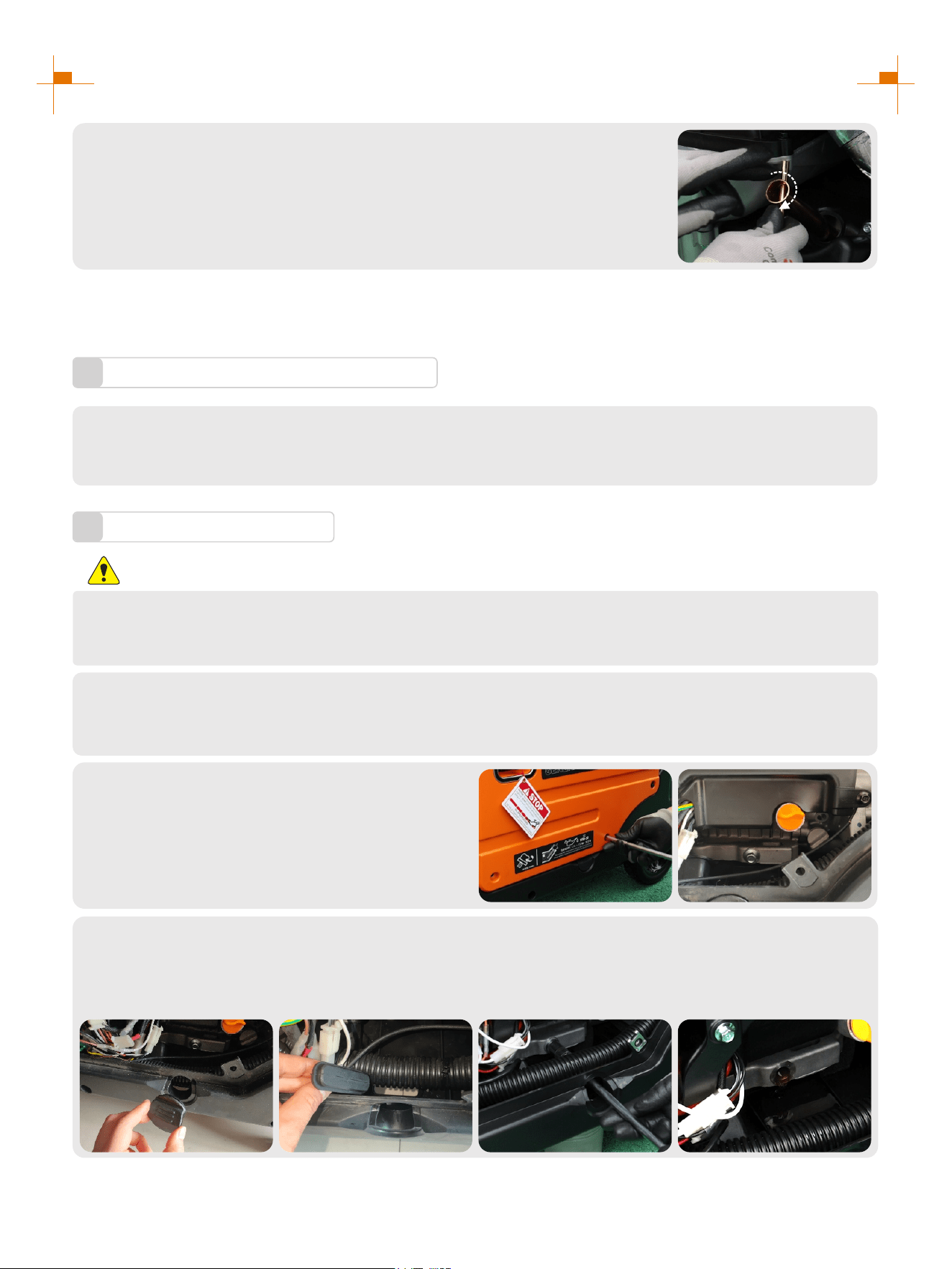
Spark Plug Inspection
1
Spark plug is an important part of the generator, which must be inspected regularly.
Remove the left panel cover, and remove the
high voltage pack;
1.
Insert the screwdriver into the sleeve, to screw it counterclockwise, and then
remove the spark plug;
2.
Check whether there is discoloration, and remove carbon deposits.Check
whether there is little pale to moderate brown on ceramic cores around
center electrode of the spark plug;
3.
Tip: The spark plug clearance is required to be measured by line thickness gauge, which shall be adjusted if
necessary.
Check the model of spark plug and clearance.
Spark plug gap: 0.7-0.8mm
Standard spark:
4.
BRANDBRAND MODEL
NGK BPR6ES
TORCH F6RTC
0.7~0.8mm
26
SERVICE AND MAINTENANCE
Install the spark plugs in reverse order of removal.
Spark plug torque: 22.5±2.5N.m(199±22in-lb)
5.
Tip: If there is no torque wrench when installing the spark plug, a better estimation method is to screw it 1/4-1/2
turns by force after screwing it in place, but the spark plug shall be screwed to specified torque as soon as possible.
Adjustment of the Carburetor
2
The carburetor is an important components of the engine. The adjustment shall be carried out by a dealer with
professional knowledge, professional data and equipment, to ensure that the adjustment is proper.
Replacement of Oil
3
WARNING
Do not drain the oil immediately after turning off the generator. Oil temperature is very high, when
operating, take care to avoid scalding.
Put the generator on a horizontal plane, start the generator, run it for a few minutes to make it warm, then
turn off the engine;
1.
2.
Open the right exterior cover, find the bolt that
put the oil in;
1. Remove the rubber plug;
2. Remove drain oil rubber plug;
3. Use containers to catch waste oil, unscrew the drain oil bolt;
4. Tighten the drain bolt after the waste oil is discharged clean, cover the rubber plug.
3.

27
SERVICE AND MAINTENANCE
Refill oil to a proper level, tighten oil dipstick,
cover external cover plate and tighten the knob.
5.
Recommended oil: SAE S10W/30
Oil grade: API standard Model SJ or higher
Volume: 0.3gal(1.1L)
Unscrew oil dipstick;
4.
Oil Filter
4
It is recommended to clean the oil filter after the first operation of the generator. After that, it will be cleaned
every 50 hours.
Drain the oil from the engine as in the previous oil drain change procedure,
and then remove the oil filter next to it;
1.
1. Clean the impurities inside the filter plug. If the impurities are too much to
clean, use detergent to clean;
2. After cleaning, blow dry with compressed air or air dry naturally and put
back in the original position.
2.
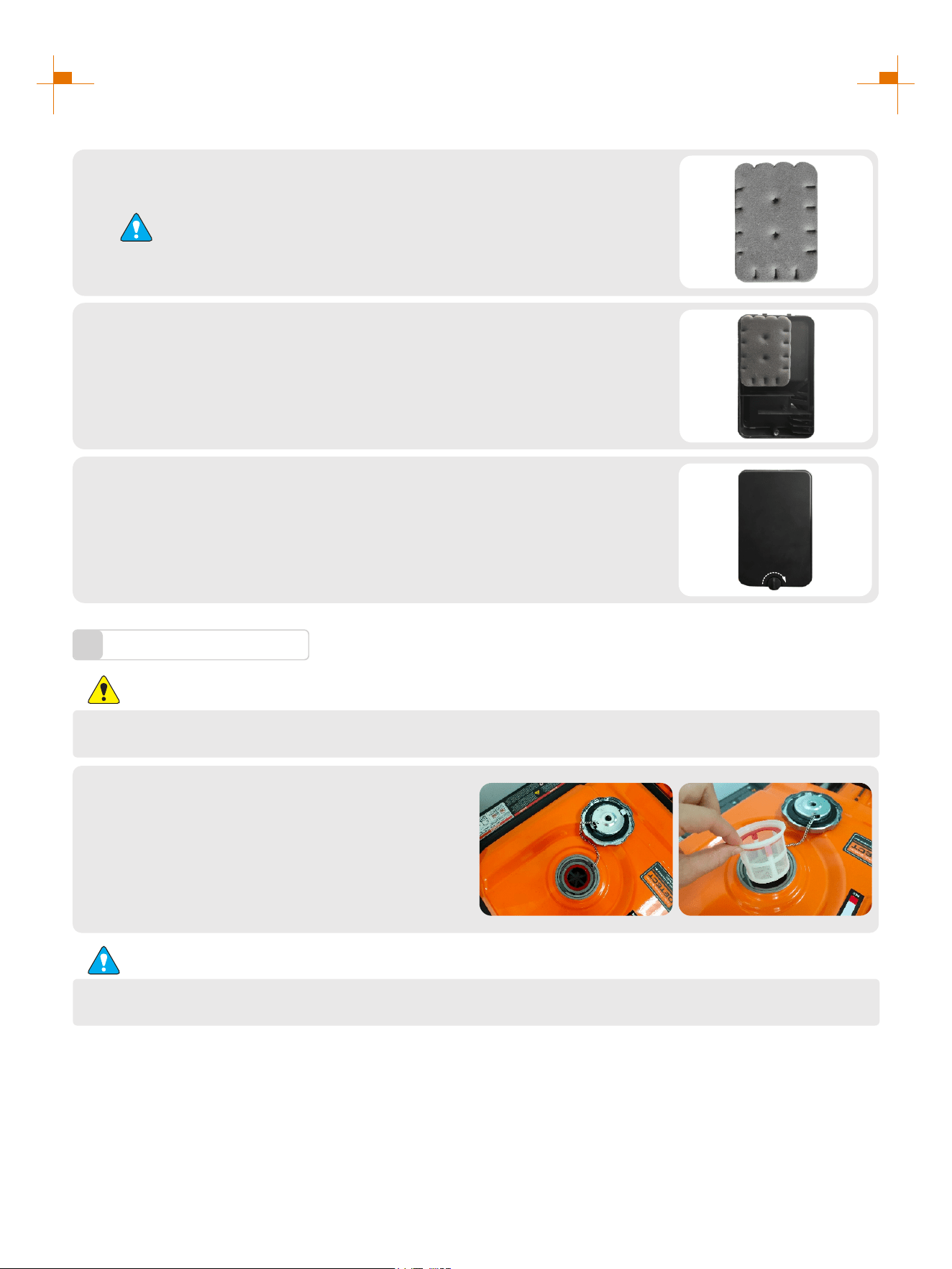
Air Filter
5
Dirty air cleaner may prevent air from flowing into the carburetor. In order to prevent failure of the carburetor,
please maintain air cleaner regularly. If being used in a dusty environment, it shall be maintained frequently.
Remove screws, to remove cover plate of air
cleaner ;
1.
28
SERVICE AND MAINTENANCE
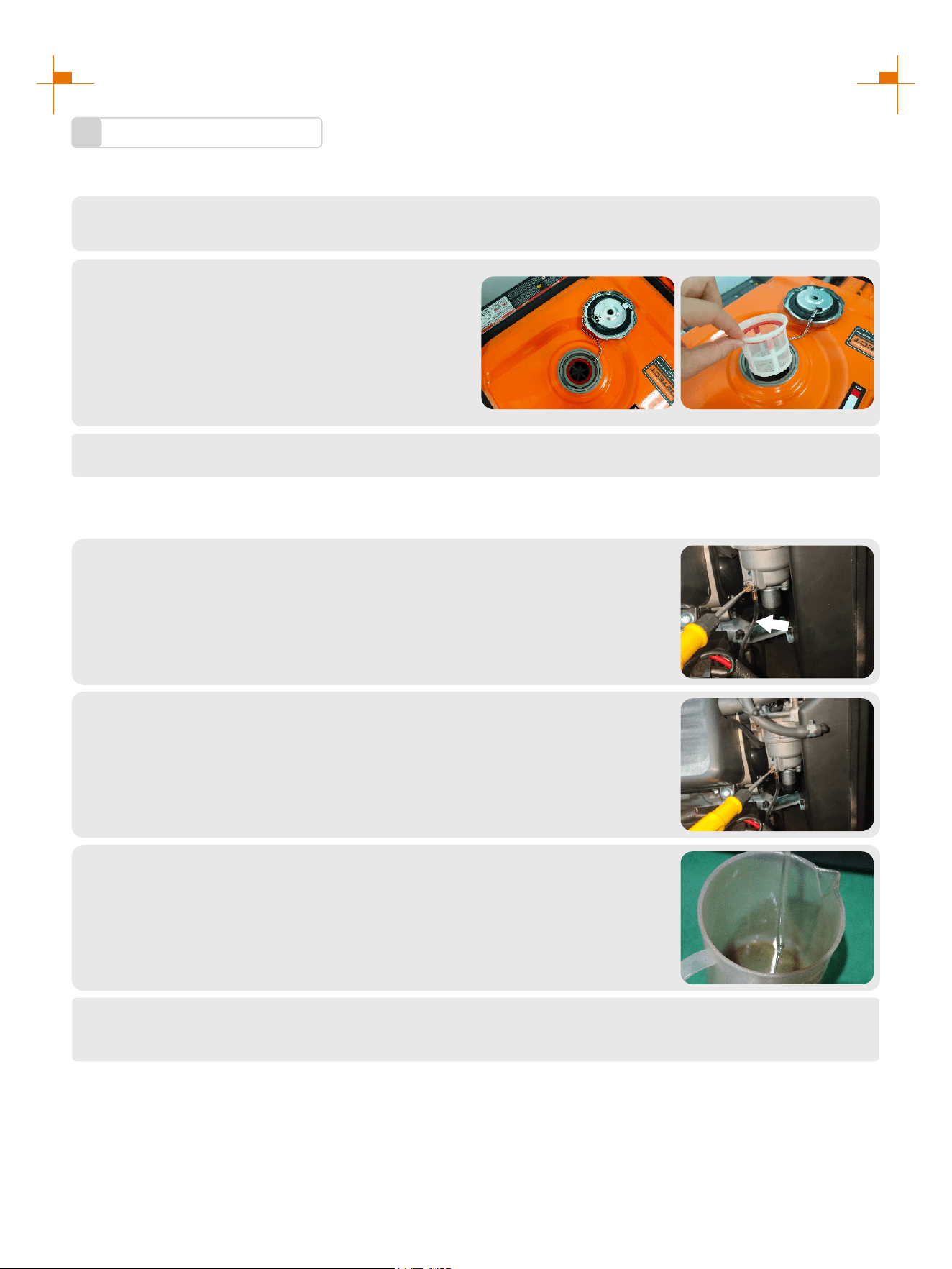
Fuel Filter Screen
6
WARNING
Be sure not to open fuel tank of the generator in a place where smoking or with flame.
1. Remove fuel tank cap and fuel tank filter screen.
2. Clean fuel tank filter screen with gasoline.
3. Wipe filter screen dry, and put it back into fuel
tank.
4. Reassemble fuel tank cap.
Be sure to screw fuel tank cap tight.
ATTENTION
Clean foam cleaner element with cleaning solvent and blow it dry, Put a few
drops of oil on the filter element.
2.
ATTENTION
Be sure not to twist the foam cleaner element forcibly to avoid damage.
Put foam cleaner element into air cleaner;
Tip: Make sure that the surface of foam cleaner element is in close contact
with air cleaner, and there shall be no gap leaking air. Be sure not to start the
engine before air cleaner is assembled, because it will generate excessive
toxic gas and wear the cylinder;
3.
1. Reassemble empty air cleaner cap back to original position, and tighten
screws;
2. Assemble left outer cover and tighten bolts.
4.
29
STORAGE AND TRANSPORT
Generator Storage
1
If it is stored long-term, in order to prevent aging, you shall take some storage measures.
Shut down generator.
1.
Open fuel tank cap, to take out fuel filter screen.
Pump all fuel in fuel tank into special fuel tank,
and then reassemble fuel tank cap back.
2.
Start up the engine to burn off fuel in the carburetor, and then shut it down.
3.
Tip: Do not connect any electrical equipment. Running time of the engine depends on remaining fuel in the fuel
tank.
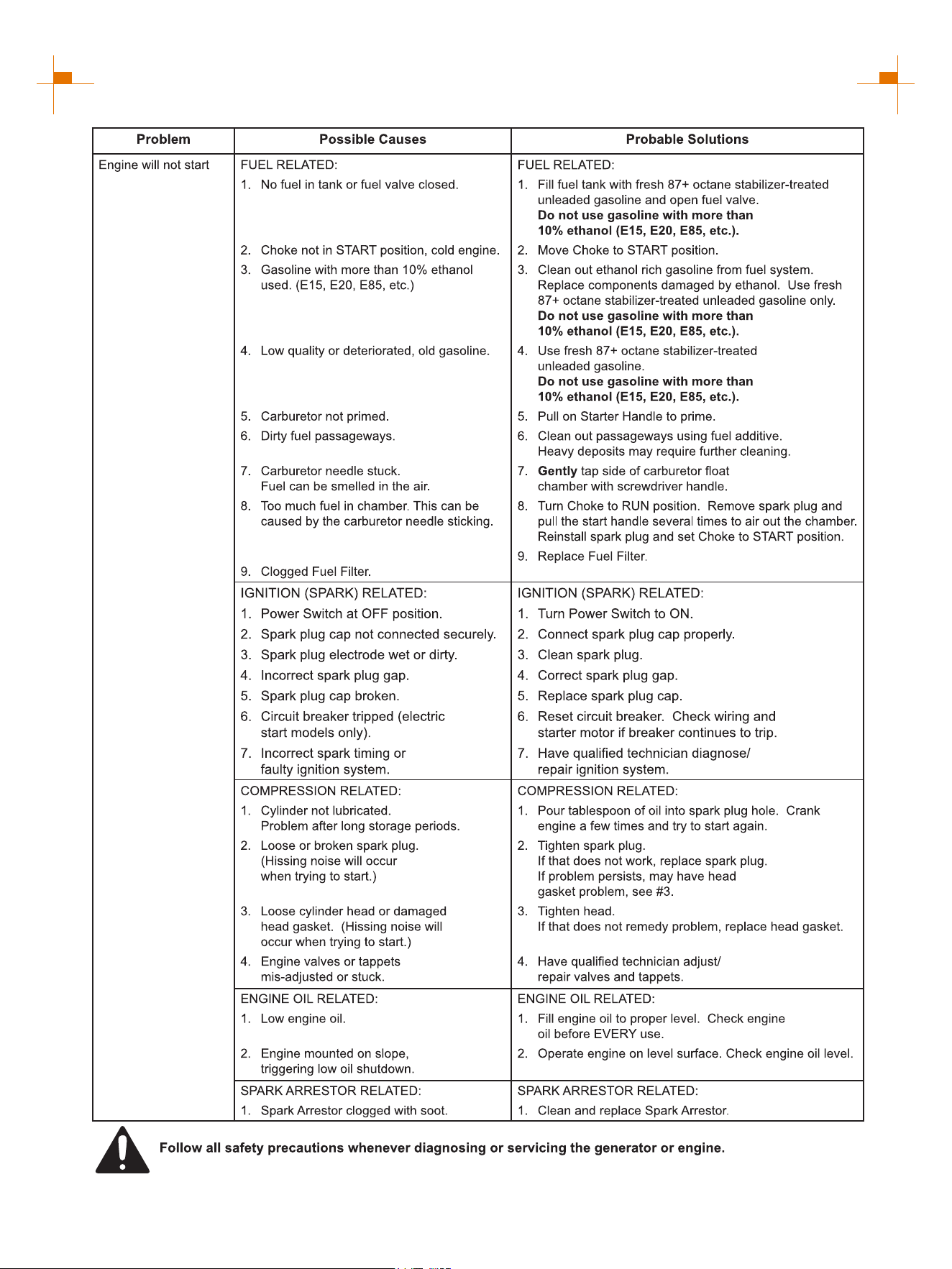
Open generator left exterior cover and enter carburetor. Locate the clear
plastic hose from the carburetor and place a suitable container under it to
capture the drained fuel.
4.
Loosen the carburetor drain screws until you see fuel draining from the
carburetor.
5.
Allow fuel to drain into the container and tighten the drain screws on the
carburetor. Install the engine service panel.
6.
Unscrew oil dipstick, and drain oil in the crankcase off. Fill new oil to upper oil limit, and then assemble
oil dipstick.
7.

30
STORAGE AND TRANSPORT
Gently pull startup handle until you feel resistance, allowing both inlet valve
and exhaust valve to be closed.
8.
Place the generator set in a clean and dry area.
10.
Generator transport
2
• When the generator set is transported, it shall be ensured that there is no fuel spilling;
• Do not fill excessive fuel into fuel tank;
• Do not run the generator, and avoid direct sunlight;
• Do not transport the generator set on rough road for long time.
Disconnect the battery cable.
9.
31
TROUBLESHOOTING
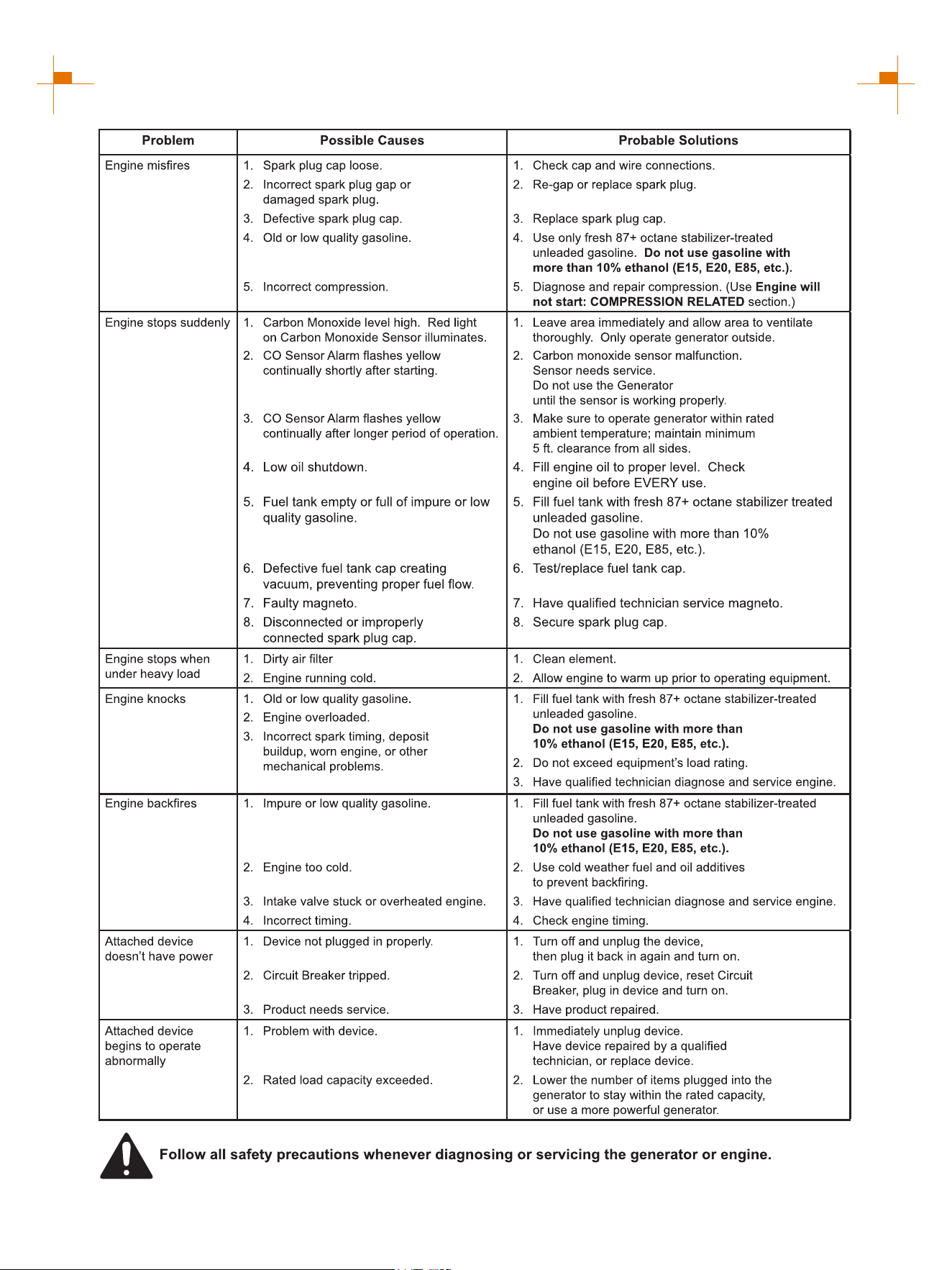
32
TROUBLESHOOTING

33
TECHNICAL PARAMETERS
Item
Engine Model
Engine Type
Displacement (cc)
Gas Distribution Mode
Cooling Mode
Rated Speed (RPM)
Starting Method
Fuel Tank Volume (gal)
Fuel Type and Grade
Lubricating Oil Capacity (gal)
Lubricating Oil Model
Forced cooling wind
Vehicle-use unleaded gasoline
Noise dB (at 7m)(25% load)
Rated Power (kW)
Max. Power (kW)
Rated Voltage (V)
Rated Frequency (Hz)
Rated Power Factor
Phase Number
Run Time @ 25% (h)
Overall Dimension (in.)
Net Weight (lb.)
GM10500iETC
OHV
3600
6.9(26L)
SAE 10W/30
0.3(1.1L)
62
8.5(GAS.)/8.0(LPG)/6.8(NG)
120/240
60
1
Single phase
Stroke × Bore (mm)
14
4-stroke
247(112kg)
Recoil start/Electrical start/Remote start
10.5(GAS.)/9.5(LPG)/8.4(NG)
458
92×69
460i
30.9×22.6×29.3(785×575×745mm)
Fuel Consumption Rate
(25% load)(L/h)
THD
Fuel Consumption Rate
(100% load)(L/h)
2.195
5.9
≤3%
LPG Consumption Rate
(25% load)(kg/h)
LPG Consumption Rate
(100% load)(kg/h)
1.65
3.43
Valve Clearance
Input valve:0.10~0.15 mm, Output valve:0.15~0.20 mm
NG Consumption Rate
(25% load)(m³/h)
NG Consumption Rate
(100% load)(m³/h)
1.296
3.27
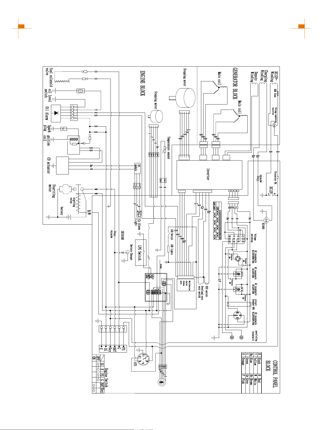
34
GM10500iETC SCHEMATICS
CIRCUIT DIAGRAM
35
R
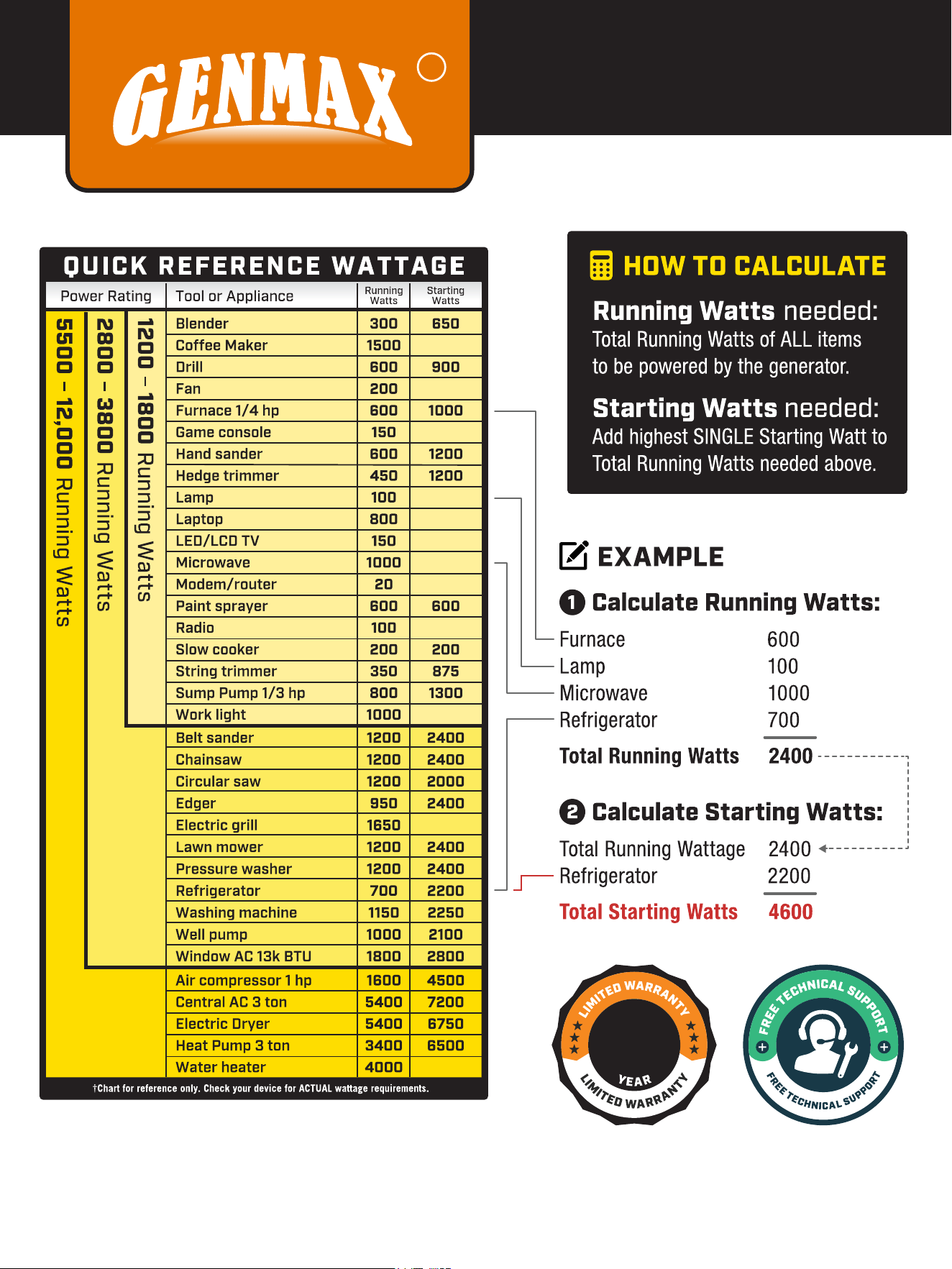
CHOOSING
A GENERATOR
1

36
In production management, based on orderly, efficient, scientific principles. trying to do as
better as possible in product design, development, production, inspection, etc. to make our
production can keep orderly. And will continue to make improvement to make sure that
keep the competitiveness.
Welcome friends at home and abroad to visit and guide, work together to create
brilliant.
Phone
866-960-2920
service@genmaxpower.com
Http://www.genmaxpower.com
Caojie Industrial Park,Hechuan District,Chongqing
E-mail
You
Tube
f
+
R
6800.J35.GEM.02.01 V6
Facebook Linkedin YouTube