Operating Instructions
Controller in a eld housing for
connecting two radio-based sensors
VEGAMET Air 842
LoRaWAN
Document ID: 1104033

2
Contents
VEGAMET Air 842 • LoRaWAN
1104033-EN-260703
Contents
1 About this document ............................................................................................................... 4
1.1 Function ........................................................................................................................... 4
1.2 Target group ..................................................................................................................... 4
1.3 Symbols used................................................................................................................... 4
2 For your safety ......................................................................................................................... 5
2.1 Authorised personnel ....................................................................................................... 5
2.2 Intended use .................................................................................................................... 5
2.3 Warning about incorrect use ............................................................................................. 5
2.4 General safety instructions ............................................................................................... 5
2.5 Installation and operation in the USA and Canada ........................................................... 6
2.6 Safety instructions for Ex areas ........................................................................................ 6
3 Product description ................................................................................................................. 7
3.1 Conguration .................................................................................................................... 7
3.2 Principle of operation........................................................................................................ 8
3.3 Adjustment ....................................................................................................................... 9
3.4 Packaging, transport and storage ................................................................................... 10
3.5 Accessories.................................................................................................................... 10
4 Mounting ................................................................................................................................. 11
4.1 General instructions ....................................................................................................... 11
4.2 Mounting instructions ..................................................................................................... 12
5 Connecting to power supply ................................................................................................. 14
5.1 Preparing the connection ............................................................................................... 14
5.2 Connecting ..................................................................................................................... 15
5.3 Wiring plan ..................................................................................................................... 15
5.4 Switch-on phase............................................................................................................. 16
6 Access protection .................................................................................................................. 17
6.1 Bluetooth radio interface ................................................................................................ 17
6.2 Protection of the parameterization .................................................................................. 17
6.3 Storing the codes in myVEGA ........................................................................................ 18
7 Set up with the integrated display and adjustment unit .................................................... 19
7.1 Adjustment system ......................................................................................................... 19
7.2 Measured value and menu item display ......................................................................... 20
7.3 Menu overview ............................................................................................................... 21
7.4 Setup steps .................................................................................................................... 22
8 Setup with smartphone/tablet (Bluetooth) .......................................................................... 28
8.1 Preparations ................................................................................................................... 28
8.2 Connecting ..................................................................................................................... 28
8.3 Parameter adjustment .................................................................................................... 29
9 Setup with PC/notebook (Bluetooth) ................................................................................... 30
9.1 Preparations ................................................................................................................... 30
9.2 Connecting ..................................................................................................................... 30
9.3 Parameter adjustment .................................................................................................... 31
10 Applications and functions ................................................................................................... 32
10.1 Application example ....................................................................................................... 32
11 Diagnostics and servicing .................................................................................................... 33

3
Contents
VEGAMET Air 842 • LoRaWAN
1104033-EN-260703
11.1 Maintenance .................................................................................................................. 33
11.2 Rectify faults ................................................................................................................... 33
11.3 Diagnosis, fault messages ............................................................................................. 33
11.4 Software update ............................................................................................................. 36
11.5 How to proceed if a repair is necessary .......................................................................... 36
12 Dismount................................................................................................................................. 37
12.1 Dismounting steps.......................................................................................................... 37
12.2 Disposal ......................................................................................................................... 37
13 Certicatesandapprovals .................................................................................................... 38
13.1 Radio licenses ................................................................................................................ 38
13.2 Conformity ...................................................................................................................... 38
13.3 Environment management system ................................................................................. 38
14 Supplement ............................................................................................................................ 39
14.1 Technical data ................................................................................................................ 39
14.2 Overview applications/functionality ................................................................................ 43
14.3 Dimensions .................................................................................................................... 45
14.4 Industrial property rights ................................................................................................. 48
14.5 Licensing information for open source software ............................................................. 48
14.6 Trademark ...................................................................................................................... 48
Editing status: 2026-03-25
4
1 About this document
VEGAMET Air 842 • LoRaWAN
1104033-EN-260703
1 About this document
1.1 Function
This instruction provides all the information you need for mounting,
connection and setup as well as important instructions for mainte-
nance,faultrectication,safetyandtheexchangeofparts.Please
read this information before putting the instrument into operation and
keep this manual accessible in the immediate vicinity of the device.
1.2 Target group
This instruction manual is directed to trained personnel. The contents
ofthismanualmustbemadeavailabletothequaliedpersonneland
implemented.
1.3 Symbols used
Document ID
This symbol on the front page of this instruction refers to the Docu-
ment ID. By entering the Document ID on www.vega.com you will
reach the document download.
Information, note, tip: This symbol indicates helpful additional infor-
mation and tips for successful work.
All sections of text marked with this warning symbol must be read
before setup.
Note: This symbol indicates notes to prevent failures, malfunctions,
damage to devices or plants.
Caution: Non-observance of the information marked with this symbol
may result in personal injury.
Warning: Non-observance of the information marked with this symbol
may result in serious or fatal personal injury.
Danger: Non-observance of the information marked with this symbol
results in serious or fatal personal injury.
Ex applications
This symbol indicates special instructions for Ex applications.
•
List
The dot set in front indicates a list with no implied sequence.
1 Sequence of actions
Numbers set in front indicate successive steps in a procedure.
Disposal
This symbol indicates special instructions for disposal.

5
2 For your safety
VEGAMET Air 842 • LoRaWAN
1104033-EN-260703
2 For your safety
2.1 Authorised personnel
All operations described in this documentation must be carried out
only by trained and authorized personnel.
During work on and with the device, the required personal protective
equipment must always be worn.
2.2 Intended use
VEGAMET Air 842 is a universal controller for connection of radio-
based sensors.
Youcannddetailedinformationabouttheareaofapplicationin
chapter "Product description".
Operational reliability is ensured only if the instrument is properly
usedaccordingtothespecicationsintheoperatinginstructions
manual as well as possible supplementary instructions.
2.3 Warning about incorrect use
Inappropriate or incorrect use of this product can give rise to applica-
tion-specichazards,e.g.vesseloverllthroughincorrectmounting
or adjustment. Damage to property and persons or environmental
contamination can result. Also, the protective characteristics of the
instrument can be impaired.
2.4 General safety instructions
This is a state-of-the-art instrument complying with all prevailing
regulations and directives. The instrument must only be operated in
atechnicallyawlessandreliablecondition.Theoperatingcompany
is responsible for the trouble-free operation of the instrument. When
measuring aggressive or corrosive media that can cause a danger-
ous situation if the instrument malfunctions, the operating company
has to implement suitable measures to make sure the instrument is
functioning properly.
During the entire duration of use, the operating company is obliged
to determine the compliance of the necessary occupational safety
measures with the current valid rules and regulations and also take
note of new regulations.
The safety instructions in this operating instructions manual, the
national installation standards as well as the valid safety regulations
and accident prevention rules must be observed.
For safety and warranty reasons, any invasive work on the device
beyond that described in the operating instructions manual may be
carried out only by personnel authorised by us. Arbitrary conversions
ormodicationsareexplicitlyforbidden.Forsafetyreasons,onlythe
accessoryspeciedbyusmustbeused.
To avoid any danger, the safety approval markings and safety tips on
the device must also be observed.

6
2 For your safety
VEGAMET Air 842 • LoRaWAN
1104033-EN-260703
2.5 Installation and operation in the USA and
Canada
This information is only valid for USA and Canada. Hence the follow-
ing text is only available in the English language.
Installations in the US shall comply with the relevant requirements of
the National Electrical Code (NEC - NFPA 70) (USA).
Installations in Canada shall comply with the relevant requirements of
the Canadian Electrical Code (CEC Part I) (Canada).
2.6 Safety instructions for Ex areas
For applications in hazardous areas (Ex), only devices with corre-
spondingExapprovalmaybeused.ObservetheEx-specicsafety
instructions. These are an integral part of the device documentation
and are enclosed with every device with Ex approval.

7
3 Product description
VEGAMET Air 842 • LoRaWAN
1104033-EN-260703
3 Product description
3.1 Conguration
The scope of delivery encompasses:
•
Controller VEGAMET Air 842
•
Mounting plate
•
Screws/plugs for mounting
•
Cable glands/Blind plugs (optional)
•
External omnidirectional dipole antenna
•
Information sheet "Documents and software" with:
– Instrument serial number
– QR code with link for direct scanning
•
Information sheet "PINs and Codes" with:
– Bluetooth access code
•
Information sheet "Access protection" with:
– Bluetooth access code
– Emergency Bluetooth unlock code
– Emergency device code
The further scope of delivery encompasses:
•
Documentation
– Ex-specic"Safety instructions" (with Ex versions)
– Radio licenses
– Ifnecessary,furthercerticates
Information:
Optional instrument features are also described in this instructions.
Therespectivescopeofdeliveryresultsfromtheorderspecication.
Scope of delivery
8
3 Product description
VEGAMET Air 842 • LoRaWAN
1104033-EN-260703
1
2
3
6
5
4
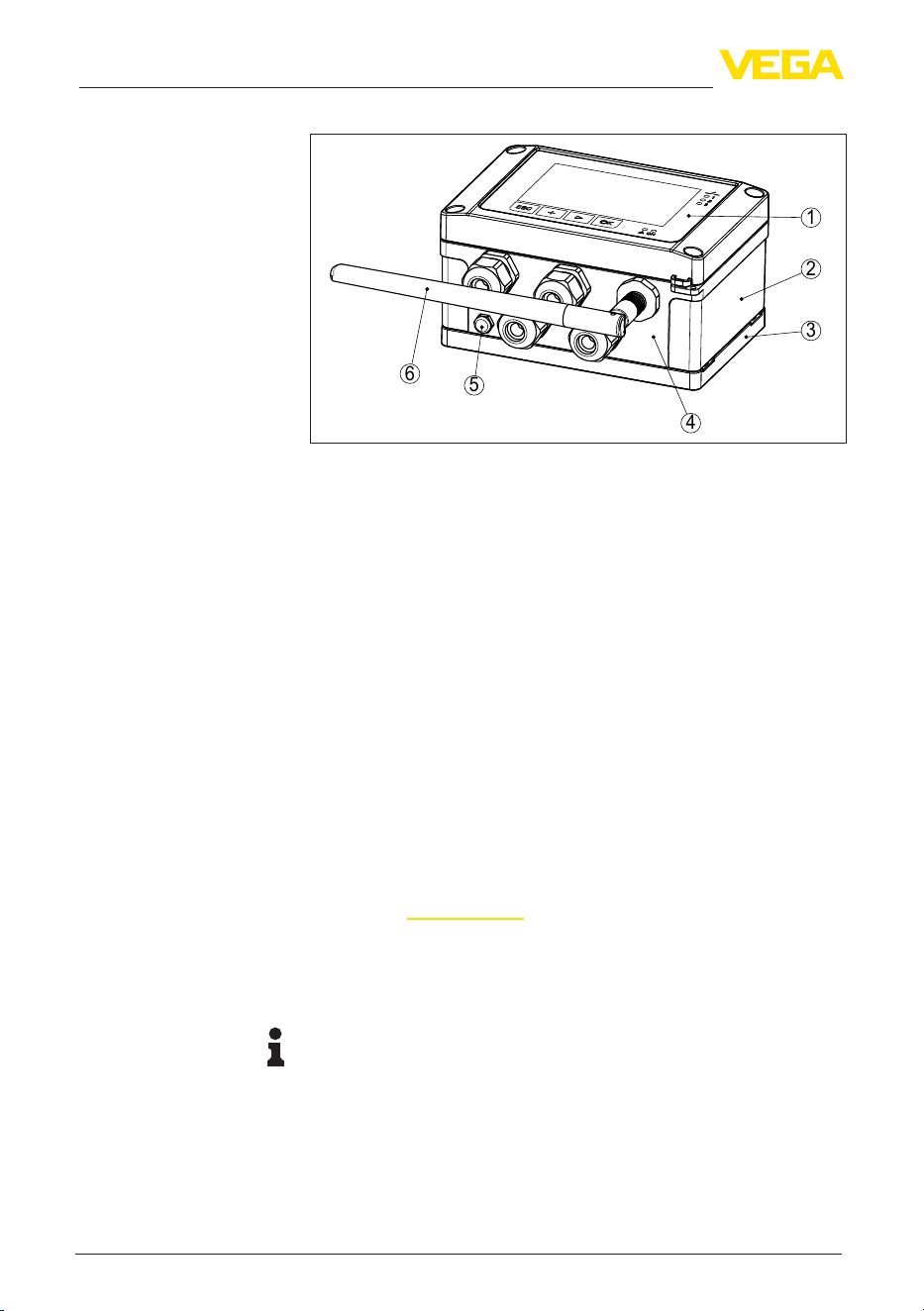
Fig. 1: VEGAMET Air 842
1 Display and adjustment unit
2 NFC reader
3 Mounting plate
4 Housing with cable glands and connection compartment
5 Ventilation/pressure compensation
6 Antenna
Thetypelabelcontainsthemostimportantdataforidenticationand
use of the instrument:
•
Instrument type
•
Information about approvals
•
Congurationinformation
•
Technical data
•
Serial number of the instrument
•
QRcodefordeviceidentication
•
Numerical code for Bluetooth access (optional)
•
Manufacturer information
Tondorderdata,documentsorsoftwarerelatedtoyourdevice,you
have the following options:
•
Move to "www.vega.com"andenterinthesearcheldtheserial
number of your instrument.
•
Scan the QR code on the type label.
•
Open the VEGA Tools app and enter the serial number under
"Documentation".
Information:
If the serial number or the QR code on the type label cannot be read,
they can be found additionally on the display cover inside the device.
3.2 Principle of operation
The controller VEGAMET Air 842 receives and processes the meas-
ured values from two wirelessly connected sensors and displays them
on the screen. A large display for data visualisation is integrated into
thehousing,whichisdesignedforharsheldconditions.
Constituent parts
Type label
Documents and software
Application area
9
3 Product description
VEGAMET Air 842 • LoRaWAN
1104033-EN-260703
Itenablessimpleimplementationofpumpcontrols,owmeasure-
mentsonopenchannelsandweirs,totalizers,dierence,sumand
average value calculations. With VEGAMET Air 842, limit values can
be monitored and relays can be switched.
The simple connection of radio-based sensors over long distances
enables applications where laying a cable would be too costly or
impossible.
The VEGAMET Air 842 controller evaluates the measurement signals
of wirelessly connected sensors. The requested parameter is shown
on the display and also output to the integrated current output for fur-
ther processing. The measurement signal can thus be transferred to a
remote display or a superordinate control system. Operating relays for
control of pumps or other devices are also integrated.
3.3 Adjustment
On-site adjustment of the device is carried out via the integrated
display and adjustment unit.
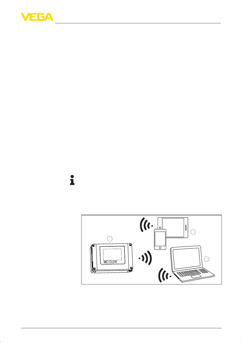
The optionally integrated Bluetooth module enables in addition a wire-
less adjustment of VEGAMET Air 842 via standard adjustment tool:
•
Smartphone/tablet (iOS or Android operating system)
•
PC/notebook with Bluetooth LE or Bluetooth USB adapter (Win-
dows operating system)
Information:
Certain setting options are not possible or only possible to a limited
extent with the integrated display and adjustment unit, for example the
settingsforowmeasurementorpumpcontrol.Fortheseapplica-
tions, the use of PACTware/DTM or the VEGA Tools app is recom-
mended. An overview of the available applications and functions as
well as their adjustment options can be found in the appendix.
1
3
2
Fig. 2: Wireless connection to standard adjustment tools with integrated
Bluetooth LE or alternatively Bluetooth USB adapter.
1 VEGAMET Air 842
2 Smartphone/Tablet
3 PC/Notebook
Functional principle
Local adjustment
Wireless adjustment

10
3 Product description
VEGAMET Air 842 • LoRaWAN
1104033-EN-260703
3.4 Packaging, transport and storage
Your instrument was protected by packaging during transport. Its
capacity to handle normal loads during transport is assured by a test
based on ISO 4180.
The packaging consists of environment-friendly, recyclable card-
board. For special versions, PE foam or PE foil is also used. Dispose
of the packaging material via specialised recycling companies.
Transport must be carried out in due consideration of the notes on the
transport packaging. Nonobservance of these instructions can cause
damage to the device.
The delivery must be checked for completeness and possible transit
damage immediately at receipt. Ascertained transit damage or con-
cealed defects must be appropriately dealt with.
Up to the time of installation, the packages must be left closed and
stored according to the orientation and storage markings on the
outside.
Unless otherwise indicated, the packages must be stored only under
the following conditions:
•
Not in the open
•
Dry and dust free
•
Not exposed to corrosive media
•
Protected against solar radiation
•
Avoiding mechanical shock and vibration
•
Storage and transport temperature see chapter "Technical data -
Ambient conditions"
•
Relative moisture 20 … 85 %
3.5 Accessories
The sun protection protects the device from direct sunlight and thus
prevents overheating of the electronics. It also improves the readabil-
ity of the display when exposed to sunlight. The sun protection can be
used for wall and pipe mounting.
The pipe mounting set is used for optimal and safe mounting of the
devices in horizontal and vertical mounting on pipes.
The remote antenna is designed to improve LoRaWAN reception
quality. It is available for wall mounting. The cable length is 3 m.
Packaging
Transport
Transport inspection
Storage
Storage and transport
temperature
Sun shade
Pipe mounting set
Remote antenna

11
4 Mounting
VEGAMET Air 842 • LoRaWAN
1104033-EN-260703
4 Mounting
4.1 General instructions
TheeldhousingoftheVEGAMETAir842isequallysuitablefor
outdoor or indoor installation due to its degree of protection IP66/IP67
and Type 4X. The standard version is designed for wall mounting. A
mounting adapter for pipe mounting is available as an option.
Install the device so that the antenna can freely radiate. If LoRaWAN
reception is poor at the mounting location – for example, if the device
is installed in a metal switching cabinet – a remote antenna can be
used (optional accessory). The cable length is 3 m.
Note:
If third-party antennas are used, the device’s radio licence of the
VEGAMET Air 842 expires.
The instrument is suitable for standard and extended ambient condi-
tions acc. to DIN/EN/BS EN/IEC/ANSI/ISA/UL/CSA 61010-1. It can be
used indoors as well as outdoors.
Avoid direct sunlight or use the optionally available sun shade.
Makesurethattheenvironmentalandambientconditionsspeciedin
chapter "Technical data" are maintained.
Protect your instrument against moisture ingress through the following
measures:
•
Use the recommended connection cable (see chapter "Connect-
ing to power supply")
•
Tighten the cable gland
•
Mount the instrument in such a way that the cable glands point
downward
•
Loop the connection cable downward in front of the cable gland
This applies mainly to outdoor installations, in areas where high
humidity is expected (e.g. through cleaning processes) and on cooled
or heated vessels.
The visible area of the front panel must be protected from knocks,
otherwise water can penetrate through breaking of the front foil. In this
case, protection against accidental contact can no longer be ensured.
Caution:
Make sure that during installation or maintenance no moisture or dirt
can get inside the instrument.
To maintain the housing protection, make sure that the housing lid is
closed during operation and locked, if necessary.
The pressure compensation for the housing is realized via a breather
element.
Mounting options
Mounting location/An-
tenna
Ambient conditions
Protection against mois-
ture
Pressure compensation
12
4 Mounting
VEGAMET Air 842 • LoRaWAN
1104033-EN-260703
Note:
Make sure that the pressure equalization element is always free of
buildup during operation. A high-pressure cleaner may not be used
for cleaning.
4.2 Mounting instructions
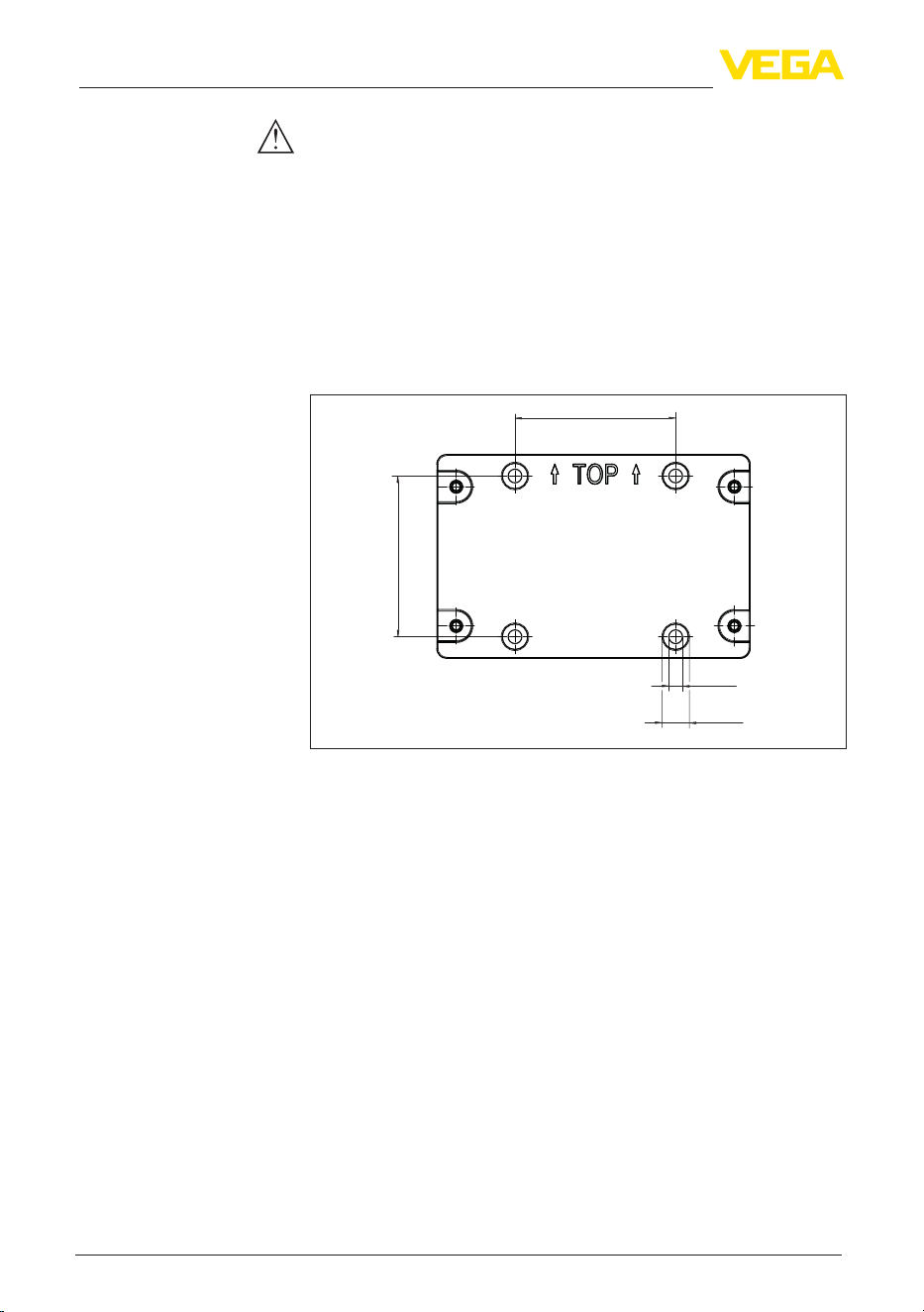
Fix the mounting plate to the wall using the screws and dowels sup-
pliedasshowninthegurebelow.Makesurethatthearrowsonthe
mounting plate point upwards.
Loosen the four screws in the housing cover and open it to the left.
Fasten the device to the mounting plate using the screws (M5) sup-
plied.
82 mm
(3.23")
ø13 mm
(0.51")
ø7 mm
(0.28")
82 mm
(3.23")
Fig. 3: Mounting plate for wall mounting VEGAMET Air 842
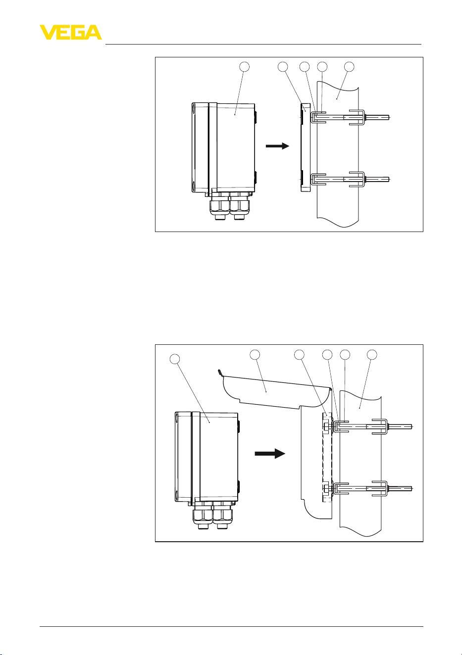
The optionally available mounting accessories are required for tube
mounting. The kit consists of two pairs of mounting brackets and four
mounting screws M6 x 100.
The mounting brackets are screwed to the mounting plate and the
tube as shown in the following illustration.
Loosen the four screws in the housing cover and open it to the left.
Fasten the device to the mounting plate using the screws (M5) sup-
plied.
Wall mounting
Tube mounting
13
4 Mounting
VEGAMET Air 842 • LoRaWAN
1104033-EN-260703
4321
5
Fig. 4: Tube mounting
1 VEGAMET Air 842
2 Mounting plate
3 4 screws M6 x 100
4 Mounting brackets
5 Pipe for diameter 29 … 60 mm (1.14" to 2.36")
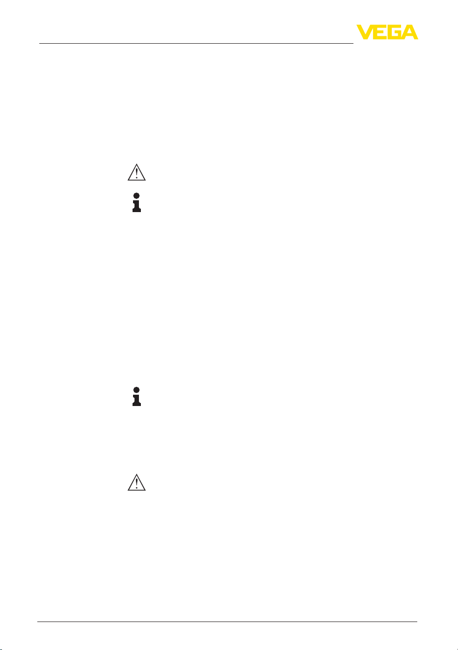
The optional sun protection can be used to protect against direct
sunlight. The sunshade is simply mounted behind the mounting plate,
this is possible for both wall and pipe mounting.
542 3
1
6
Fig. 5: Mounting sun protection with pipe mounting
1 VEGAMET Air 842
2 Sun shade
3 Mounting plate
4 4 screws M6 x 100
5 Mounting brackets
6 Pipe for diameter 29 … 60 mm (1.14" to 2.36")
Mounting sun shade
14
5 Connecting to power supply
VEGAMET Air 842 • LoRaWAN
1104033-EN-260703
5 Connecting to power supply
5.1 Preparing the connection
Always keep in mind the following safety instructions:
•
The electrical connection must only be carried out by trained,
qualiedpersonnelauthorisedbytheplantoperator.
•
If overvoltage surges are expected, overvoltage arresters should
be installed.
Warning:
Only connect or disconnect in de-energized state.
Note:
Install a disconnecting device for the instrument which is easy to
access. The separation facility must be designed and rated for the
power consumption of the instrument (IEC/EN 61010).
Thedataforpowersupplyarespeciedinchapter"Technical data".
The instrument belongs to protection class I, hence connection of an
earth conductor is required.
Use cables with a round cross-section. The cable diameter must
matchthecableglandusedtoensurethesealeectivenessofthe
cable gland (IP rating). The permissible cable diameters and torque
arespeciedinthetechnicaldata.Ifthecableglandssuppliedarenot
used,orifthecablediameterisoutsidethespeciedrange,theIP67
protection rating cannot be guaranteed.
The voltage supply is connected with standard cable according to the
national installation standards.
Note:
If the temperatures are too high, the cable insulation can be dam-
aged. Hence keep apart from the ambient temperature also the self-
heating of the instrument for the temperature resistance of the cable
in the connection compartment in mind.
1)
When used in the USA/Canada, only cables with copper conductors
may be used.
Warning:
Indeliverystatus,allopeningsarettedwithdustprotectioncaps.
These caps are only for protection during transport and are not suit-
able for protection during operation! Instead, all openings must be
closed with cable glands/blind plugs.
Cable glands, NPT adapters or blind plugs that are not included in
the scope of delivery must meet the applicable requirements in order
to ensure the environmental compatibility of the housing. For outdoor
Safety instructions
Voltage supply
Connection cable
Cable glands
1)
Withanambienttemperature≥50°C(122°F)theconnectioncableshould
besuitableforanambienttemperaturewhichisatleast20°C(36°F)higher.
15
5 Connecting to power supply
VEGAMET Air 842 • LoRaWAN
1104033-EN-260703
applications, the weather resistance of the accessories to be used
must be taken into account. The cable glands, NPT adapters and
blind plugs must have a metric thread M20 to be compatible with the
threaded openings of the metal plate in the housing.
5.2 Connecting
The voltage supply and outputs are connected via the spring-loaded
terminals.
Information:
Solidcoresaswellasexiblecoreswithwireendsleevesare
inserteddirectlyintotheterminalopenings.Incaseofexiblecores
without end sleeves, a small screwdriver must be pressed into the
rectangular opening so that the terminal opening is then free. When
the screwdriver is pulled out, the terminals are closed again.
Youcanndfurtherinformationonthemax.wirecross-sectioninthe
technical data.
Connect the device as described in the following wiring plan.
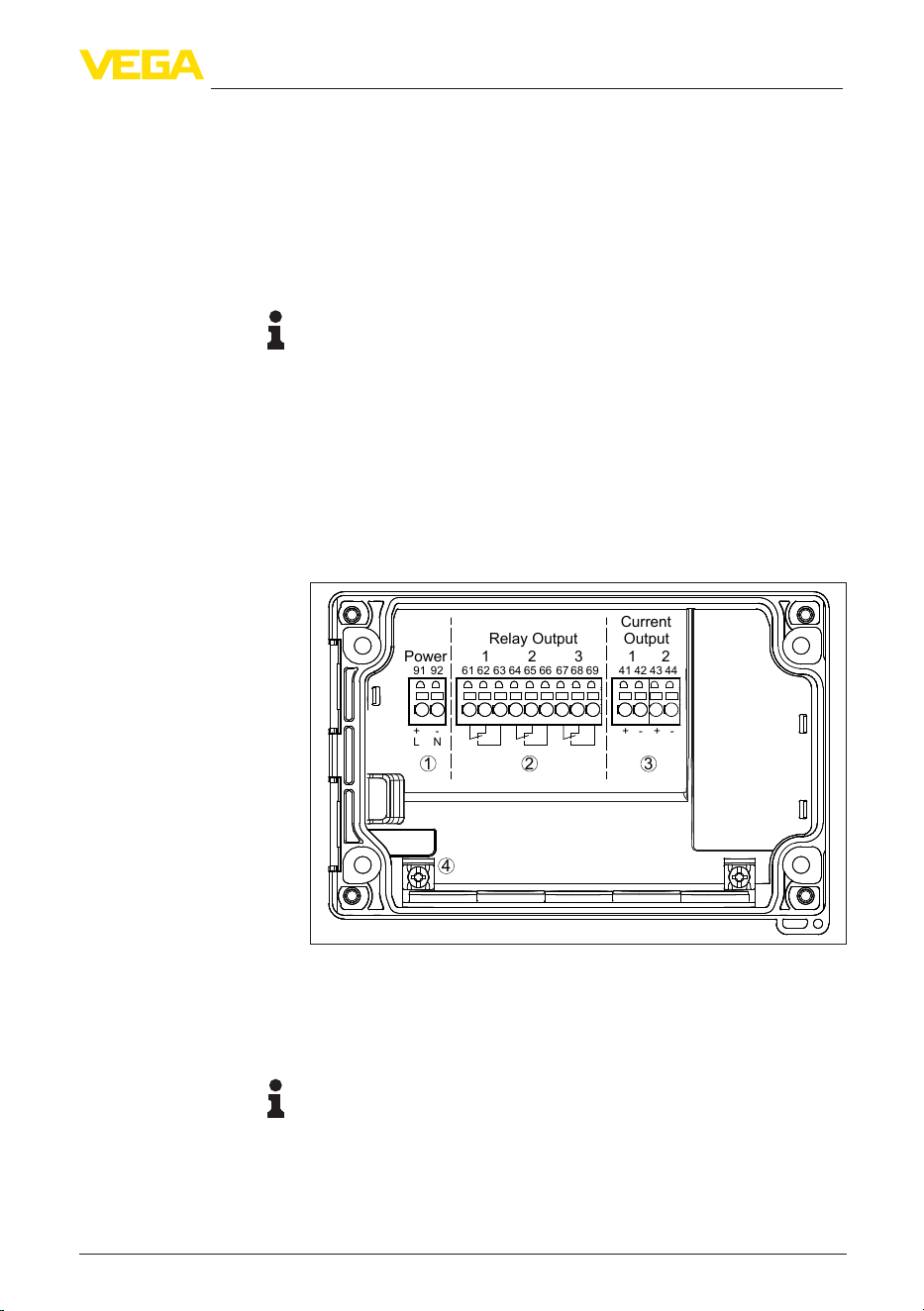
5.3 Wiring plan
1 2
91 92
L N
+ - + - + -
61 62 63 64 65 66 67 68 69
41 42 43 44
Power 321
Relay Output Output
Current
1 2
3
4
Fig. 6: Wiring plan VEGAMET Air 842
1 Voltage supply of the controller
2 Relay outputs 1 … 3
3 Current outputs 1/2
4 Ground terminal for protective conductor
Note:
Mixed operation with hazardous voltages (> 30 V AC, > 60 V DC) and
non-hazardous voltages (< 30 V AC, < 60 V DC) is not permitted for
the relay outputs.
Connection technology
Connecting

16
5 Connecting to power supply
VEGAMET Air 842 • LoRaWAN
1104033-EN-260703
5.4 Switch-on phase
Afterswitchingon,thedevicerstcarriesoutashortself-check.
•
Internal check of the electronics
•
Output signals are set to malfunction, backlight of the display
lights red
The current measured values are then displayed and transmitted to
the outputs. The backlight of the display changes to white.

17
6 Access protection
VEGAMET Air 842 • LoRaWAN
1104033-EN-260703
6 Access protection
6.1 Bluetooth radio interface
Devices with a Bluetooth radio interface are protected against un-
wanted access from outside. This means that only authorized persons
can receive measured and status values and change device settings
via this interface.
Information:
If no Bluetooth connection to the device should be possible, Bluetooth
communication can be deactivated. Access via app or DTM is thus no
longer possible. The Bluetooth function can be deactivated/activated
in the menu item "Extended functions" under "Access protection -
Bluetooth communication".
A Bluetooth access code is required to establish Bluetooth com-
munication via the adjustment tool (smartphone/tablet/notebook).
This code must be entered once when Bluetooth communication is
establishedforthersttimeintheadjustmenttool.Itisthenstoredin
the adjustment tool and does not have to be entered again.
The Bluetooth access code is individual for each device. It is printed
on the device housing and is also supplied with the device in the
information sheet "PINs and Codes". The Bluetooth access code can
also be read out via the display and adjustment unit.
TheBluetoothaccesscodecanbechangedbytheuseraftertherst
connection is established. If the Bluetooth access code is entered
incorrectly, the new entry is only possible after a waiting period has
elapsed. The waiting time increases with each further incorrect entry.
The emergency Bluetooth access code enables Bluetooth communi-
cation to be established in the event that the Bluetooth access code
is no longer known. It can't be changed. The emergency Bluetooth
access code can be found in information sheet "Access protection".
If this document is lost, the emergency Bluetooth access code can
be retrieved from your personal contact person after legitimation.
The storage and transmission of Bluetooth access codes is always
encrypted (SHA 256 algorithm).
6.2 Protection of the parameterization
The settings (parameters) of the device can be protected against un-
wanted changes. The parameter protection is deactivated on delivery,
all settings can be made.
To protect the parameterization, the device can be locked by the user
with the aid of a freely selectable device code. The settings (param-
eters) can then only be read out, but not changed. The device code
is also stored in the adjustment tool. However, unlike the Bluetooth
access code, it must be re-entered for each unlock. When using the
adjustment app or DTM, the stored device code is then suggested to
the user for unlocking.
Bluetooth access code
Emergency Bluetooth
unlock code
Device code

18
6 Access protection
VEGAMET Air 842 • LoRaWAN
1104033-EN-260703
The emergency device code allows unlocking the device in case the
device code is no longer known. It can't be changed. The emergency
device code can also be found on the supplied information sheet "Ac-
cess protection". If this document is lost, the emergency device code
can be retrieved from your personal contact person after legitimation.
The storage and transmission of the device codes is always encrypt-
ed (SHA 256 algorithm).
6.3 Storing the codes in myVEGA
If the user has a "myVEGA" account, then the Bluetooth access code
as well as the device code are additionally stored in his account under
"PINs and Codes".Thisgreatlysimpliestheuseofadditionaladjust-
ment tools, as all Bluetooth access and device codes are automati-
cally synchronized when connected to the "myVEGA" account
Emergency device code
19
7 Set up with the integrated display and adjustment unit
VEGAMET Air 842 • LoRaWAN
1104033-EN-260703
7 Set up with the integrated display and
adjustment unit
7.1 Adjustment system
The integrated display and adjustment unit is used for measured
value display, adjustment and diagnosis of the VEGAMET Air 842.
Display and adjustment are carried out via four keys and a graphic-
capable display with background lighting.
Certain setting options are not possible or only possible to a limited
extent with the integrated display and adjustment unit, for example the
settingsforowmeasurementorpumpcontrol.Fortheseapplica-
tions, the use of PACTware/DTM or the VEGA Tools app is recom-
mended. A tabular overview of the corresponding applications and
functions can be found in the appendix.
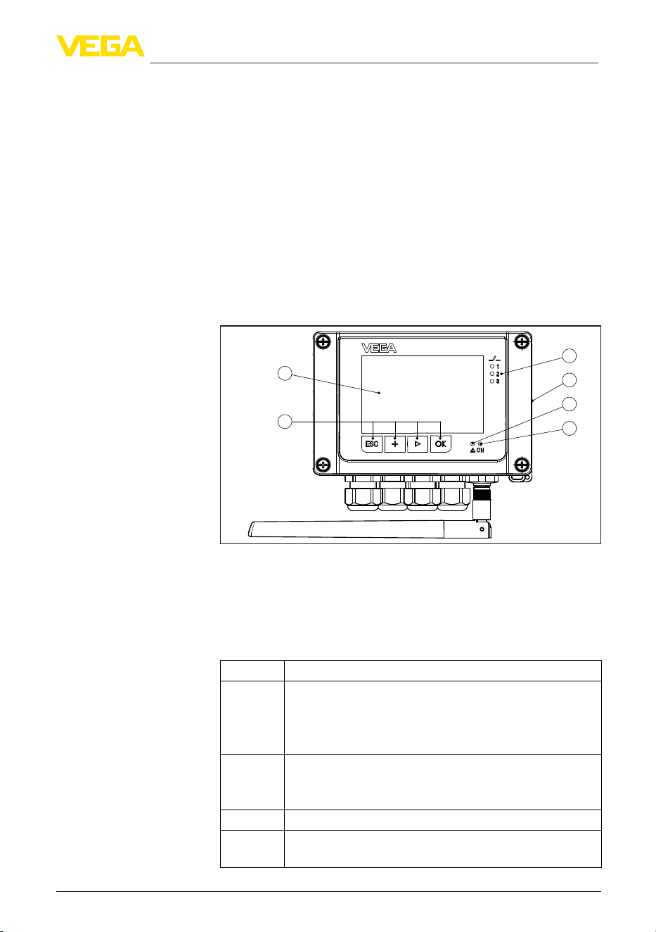
1
3
4
2
5
6
Fig. 7: Display and adjustment elements
1 LC display
2 Adjustment keys
3 Status indication relay
4 NFC reader
5 Status indication fault signal
6 Status indication operation
Key Function
[OK] Entry to the menu level
Jump to selected menu item
Edit parameter
Save value
[>] Switching between the individual measured value indications
Navigation in the menu items
Select editing position
[+] Change parameter values
[ESC] Jump to next higher menu
Interrupt input
Function
Display and adjustment
elements
Key functions
20
7 Set up with the integrated display and adjustment unit
VEGAMET Air 842 • LoRaWAN
1104033-EN-260703
When the [+] and [->] keys are pressed quickly, the edited value,
or the cursor, changes one value or position at a time. If the key is
pressed longer than 1 s, the value or position changes continuously.
Approx. 60 minutes after the last pressing of a key, an automatic reset
tomeasuredvalueindicationistriggered.Anyvaluesnotconrmed
with [OK] will not be saved.
7.2 Measured value and menu item display
The measured value display shows the digital display value, the
measuring loop name (measuring loop TAG) and the unit. In addition,
an analogue bar graph can be displayed. Up to three measured value
indicationswithamaximumthreedierentmeasuredvaluescanbe
congured.Ifpumpcontrolisactivated,anadditionalstatusbarwith
display of the assigned pumps is available.
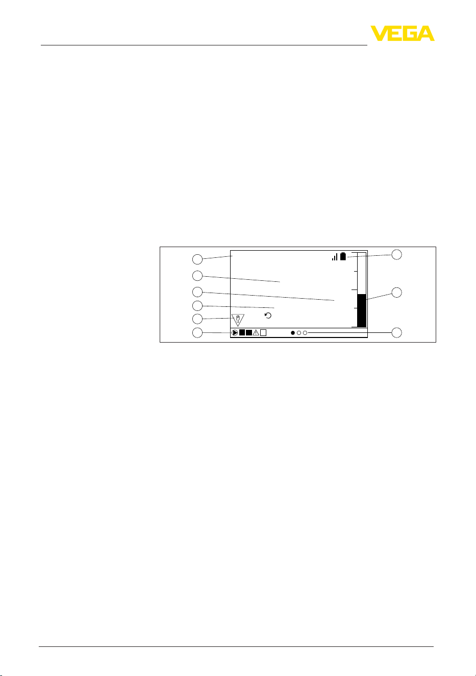
Measured values are displayed according to the following presenta-
tion:
1
2
3
5
4
6
8
9
7
PULS 78209666
m
Last Value
5 Mins ago
1.8523
1 2
Fig. 8: Example measured value indication (measured value with bargraph)
1 Measurement loop name
2 Measured value
3 Unit
4 Last transmitted measured value
5 Status message acc. to NAMUR NE 107
6 Status bar for pump control
7 Active measured value indication
8 Bargraph measured value
9 Signal strength indicator (LoRa) and battery level (sensor)
The display is equipped with a backlight for better visibility. It serves
simultaneously as a status display which is also visible from a great
distance. The colour of the background lighting changes in the deliv-
ery status according to NAMUR NE 107.
•
White: Error-free operation
•
Red: Failure, error, malfunction
•
Orange: Function check
•
Blue: Maintenance required
•
Yellow:Outsidethespecication
Alternatively, the status display can also show the switching status of
therelaysormeasuredvaluerangesindividuallywithfreelydenable
colours.Uptovemeasuredvalueranges,e.g.,dependingonthe
llinglevel,canbedisplayedindierentcolours.Thebackground
lightingcanalsobeconguredtoashinanycolourasanadditional
signalling option.
Time functions
Measured value indica-
tion
Status display/backlight
21
7 Set up with the integrated display and adjustment unit
VEGAMET Air 842 • LoRaWAN
1104033-EN-260703
Information:
ThisindividualcoloursignallingisconguredwithPACTware/DTMor
the VEGA Tools App.
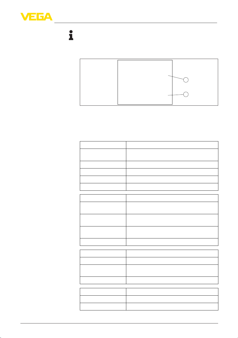
The menu items are displayed according to the following presentation:
1
2
Max.Adjustment
Sensor value at 100% :
Current Sensor value:
1.8523
m
14,83
m
Fig. 9: Menu item display (example)
1 Sensor measured value at 100 %
2 Current sensor measured value
7.3 Menu overview
Description Basic settings
Sensor input Allocation measuring point - input, deactivate
measuring point 2
Linearisation Linearization settings
Adjustment Adjustment settings
Scaling Scaling settings
Outputs Relay/current output settings
Description Basic settings
Number of measured
value indications
Number of displayed measured value indications
Measured value indi-
cation
Settings for the measured value displays, automatic
change of the measured value display
Options Display options e.g. brightness, contrast, illumina-
tion
Menu language Language settings
Description Basic settings
Fail safe relay Activate/deactivate fail safe relay
Access protection Access protection for Bluetooth and protection of
the parameter adjustment
Reset Reset of the device
Description Basic settings
Status Status indication, e.g. device, sensor, relay
Simulation Simulation function
Menu item display
Measurement loop
Indication
Extended functions
Diagnostics
22
7 Set up with the integrated display and adjustment unit
VEGAMET Air 842 • LoRaWAN
1104033-EN-260703
Description Basic settings
Device-TAG Display device name
Device information Device information, e.g. serial number
7.4 Setup steps
TherststepistopairthesensorwithVEGAMETAir842.WithVEGA
sensors his is done very easily and automatically via the built-in NFC
reader.
Through parameter adjustment, the instrument is adapted to the indi-
vidual application conditions. A measurement loop calibration is the
most important step and should always be carried out. A scaling of
the measured value to the desired physical variable and unit, possibly
including a linearization curve, is often useful. The adaptation of the
relay switching points is a further standard adjustment option.
Information:
When using PACTware and the respective DTM or the
VEGA Tools app, additional settings can be carried out which are
not possible or only partly possible with the integrated display and
adjustment unit. Communication takes place via the built-in Bluetooth
interface.
Thedeviceisconguredexworksforuniversalapplications.The
followingapplicationscanbechangedoverandconguredviathe
VEGA Tools app or the DTM:
•
Universal
•
Level - storage tank
•
Calculation-dierence
•
Calculation - total
•
Calculation - average value
•
Wells
•
Pumping station
•
Sewage screw lifting station
•
Screen control
•
Flowmeasurementume/weir
•
Density
•
Pressurized vessel
•
Overowbasin
Information:
An overview of the available applications and functions can be found
in the appendix
This function allows the VEGA LoRa sensors to be paired with the
VEGAMET Air 842 quickly and easily. When the function is launched,
the built-in NFC reader is activated for 30 seconds. If the LoRa sensor
is held against the right-hand side of the VEGAMET Air 842 during
this time, the two devices will pair automatically. If a sensor is already
connected, it can be replaced by the new one.
Pair the sensor
Parameter adjustment
Applications
Add/exchange a sensor

23
7 Set up with the integrated display and adjustment unit
VEGAMET Air 842 • LoRaWAN
1104033-EN-260703
The menu is divided into four areas with the following functions:
•
Measuring point: Includes settings for adjustment, linearization,
scaling, relay outputs, …
•
Display: Contains settings for display of measured values
•
Extended functions: Includes settings for fail safe relay, access
protection, reset, …
•
Diagnosis Includes information on device type/status, …
7.4.1 Measurement loop
The VEGAMET Air 842 is designed for the connection of two
independent sensors. Thus two independent measurements can
be carried out. Furthermore, a third measuring point can be used to
calculate a new value between the two input values.
With the menu item "Sensor input" you can determine which of the
two inputs is assigned to measurement loop 1 or measurement loop
2. The following assignment is factory set:
•
Measuring point 1 -> Sensor input 1
•
Measuring point 2 -> Sensor input 2
If measuring point 2 is not used, it can be deactivated using this func-
tion. This has the advantage that no fault signal is issued if the sensor
input is not connected.
A linearisation is necessary for all vessels in which the vessel volume
does not increase linearly with the level, for example a horizontal
cylindrical or spherical tank. Corresponding linearisation curves are
preprogrammed for these vessels. They represent the correlation
between the level percentage and vessel volume. By activating the
appropriate curve, the volume percentage of the vessel is displayed
correctly. If the volume should not be displayed in percent but e.g. in l
or kg, a scaling can be also set.
Whensettingupaowmeasurement,alinearizationcurvesuitable
for the structural conditions must be selected. Corresponding curves
suchasventuri,triangularoverow,…areavailablehere.Inaddition,
individual, user-programmable linearisation curves can be stored via
DTM.
Through the adjustment the input value of the connected sensor is
converted into a percentage value. This conversion step allows any
input value range to be depicted in a relative range (0 % up to 100 %).
The percentage values can be used for presentation on the display,
for direct use in an output or for further conversion via linearization or
scaling.
When using the display and adjustment unit, the adjustment unit
is always the physical measured value of the sensor. When using
PACTware/DTM or the VEGA Tools app, further units can be selected.
If these have been activated, they are also shown in the display.
Menu
Allocate sensor input
Deactivate measuring
point 2
Linearisation
Adjustment

24
7 Set up with the integrated display and adjustment unit
VEGAMET Air 842 • LoRaWAN
1104033-EN-260703
Min. adjustment (empty vessel)
If you want to use the currently measured level as a 0 %value, select
the menu item "Accept" (live adjustment or adjustment with medium).
If the adjustment is to be carried out independently of the measured
level, select the option "Edit". Now enter the appropriate measured
value for the empty vessel (0 %) (dry adjustment or adjustment with-
out medium).
Max. adjustment (full vessel)
If you want to use the currently measured level as a 100 %value,
select the menu item "Accept" (live adjustment or adjustment with
medium). If the adjustment is to be carried out independently of the
measured level, select the option "Edit". Now enter the appropriate
measured value for the full vessel (100 %) (dry adjustment or adjust-
ment without medium).
Scaling means converting the measured value into a certain param-
eter and unit. The linearized percentage value is the source signal
which is used as basis for the scaling. The indication can then show
the volume in litres e.g., instead of the percentage value. Indication
values from max. -9999999 to +9999999 are possible.
A total of three relays is available. Relays 1 … 2 are freely available
and not yet assigned to a function. To be able to use these relays, they
mustrstbeactivated.Relay3isconguredinthefactoryasafail
saferelay,butcanalsobeconguredasadditionaloperatingrelay.
After activating a relay output, the desired mode of operation must
rstbeselected("Overll protection/Dry run protection").
•
Overllprotection:Relayisswitchedowhenthemax.levelis
exceeded (safe currentless state), relay is switched on again when
thelevelfallsbelowthemin.level(switch-onpoint<switch-o
point)
•
Dry run protection:Relayisswitchedowhenthelevelfalls
below the min. level (safe currentless state), relay is switched on
again when the max. level is exceeded (switch-on point > switch-
opoint)
Additional modes such as "Pump control", "Switching window",
"Flow" and "Tendency" can be only set via PACTware/DTM or the
VEGA Tools app.
In the menu item "Reference value"itisdenedwhichmeasured
value serves as input signal for the relay (percentage/lin.-percent/
scaled).
EnterthevaluesforswitchingtherelayonandounderEnterthe
valuesforswitchingtherelayonandounder"Switching point".
The menu item "Behaviour in case of malfunction"deneshowthe
relay behaves if the assigned measuring point is disturbed. Here
it can be selected whether the switching state of the relay remains
unchangedorwhethertherelayisswitchedointheeventofa
malfunction.
Scaling
Outputs - Relay outputs

25
7 Set up with the integrated display and adjustment unit
VEGAMET Air 842 • LoRaWAN
1104033-EN-260703
The current output is used to transfer the measured value to a super-
ordinate system, e.g. a PLC, a process control system or a measured
value indication. This is an active output, i.e. the current is provided
actively. The processing must hence have a passive current input. If
thecurrentoutputisnotused,itcanbedeactivatedintherstmenu
item.
The characteristics of the current output can be set to 0 … 20 mA,
4 … 20 mA or inverted. The reaction in case of failure can also be
adapted to the requirements. The reference value you refer to can
also be selected.
7.4.2 Indication
Theindicationcandisplayuptothreedierent,user-congurable
measuredvaluessimultaneously.Inaddition,uptothreedierent
measuredvalueindicationscanbecongured,whichcanbeselected
using the arrow keys. Alternatively, the display of the measured value
indications can also be changed automatically at intervals of approx.
3 seconds.
In the menu item "Display - Number of measured value indications"
youcancongurehowmanymeasuredvalueindicationsaretobe
displayed.
Thecontentofthemeasuredvalueindicationisconguredinthe
menu item "Display - Measured value indication".Upto3dier-
ent measured values can be displayed in one indication. For each
measuredvalueitisalsopossibletocongurewhichdisplayvalue
(percent, scaled, sensor value, …) is displayed. In addition, the dis-
playformat(numberofdecimalpositions)canalsobecongured.In
addition, a bar graph can be displayed parallel to the measured value
(only available when displaying a single measured value).
In the menu item "Display - Options - Brightness" the brightness of the
backlight can be adjusted.
In the menu item "Display - Options - Contrast" the contrast of the
display can be adjusted.
In the menu item "Display - Options - Lighting" the lighting can be set
permanently to "Permanently ON" or "Automatically OFF" (after two
minutes). With the setting "Automatically OFF" the lighting is switched
on for two minutes as soon as any button is pressed.
In the menu item "Display - Menu language", the requested language
can be adjusted. The following languages are available:
•
German
•
English
•
French
•
Spanish
•
Portuguese
•
Italian
•
Dutch
Outputs - Current output
Number of measured
value indications
Measured value indica-
tion 1 … 3
Options - Brightness
Options - Contrast
Options - Lighting
Menu language

26
7 Set up with the integrated display and adjustment unit
VEGAMET Air 842 • LoRaWAN
1104033-EN-260703
•
Russian
•
Chinese
•
Japanese
•
Turkish
7.4.3 Extended functions
Relay3canoptionallybeconguredasadditionaloperatingrelayor
as a fail safe relay. In this menu item, the fail safe relay can be activat-
edordeactivated.Ifrelay3istobeconguredasanoperatingrelay,it
must still be activated as an operating relay after deactivation as a fail
safe relay. This is done in menu item"Measuring point - Relay 3"
Bluetooth communication can be activated/deactivated in this menu
item. If Bluetooth communication is deactivated, a connection via app
or DTM is no longer possible.
Youcanndfurtherdetailsinchapter"Access protection".
Bluetooth communication is encrypted to prevent unauthorized
access. The Bluetooth access code required for communication is
displayed here and can be changed as required.
Note:
The individual, default Bluetooth access code of the device can be
found on the device housing and on the supplied information sheet
"PINs and Codes". If this has been changed by the user and is no
longer known, access is only possible via the emergency Bluetooth
accesscode.YoucanndtheemergencyBluetoothaccesscodeon
the supplied information sheet "Access protection"
Youcanndfurtherdetailsinchapter"Access protection".
The device parameters can be protected against unwanted or unin-
tended changes by entering a device code.
With activated protection of the parameter adjustment, the individual
menu items can be selected and displayed, however the parameters
cannolongerbemodied.
Releasing the device adjustment is also possible in any menu item by
entering the device code.
Note:
The default device code is "000000". If this has been changed by the
user and is no longer known, access is only possible via the emer-
gencydevicecode.Youwillndtheemergencydevicecodeonthe
supplied information sheet "Access protection"
Caution:
With protected parameter adjustment, adjustment via the
VEGA Tools app as well as PACTware/DTM and other systems is also
blocked.
Youcanndfurtherdetailsinchapter"Access protection".
Fail safe relay
Access protection -
Bluetooth communication
Access protection -
Bluetooth access code
Access protection - Pro-
tection of the parameter
adjustment

27
7 Set up with the integrated display and adjustment unit
VEGAMET Air 842 • LoRaWAN
1104033-EN-260703
With a reset to basic setting, all settings except the display language
and the Bluetooth access code are reset to factory settings. If desired,
the device can also be restarted.
7.4.4 Diagnostics
When the instrument displays a fault signal, further information about
the malfunction can be called up via the menu item "Diagnosis -
Status". Furthermore, the sensor status with temperature and location
can be displayed. The status of the relay, its switched-on period and
the number of switch-on events can also be displayed. The counters
can also be reset.
The simulation of a measured value is used to check the outputs and
connected components. It can be applied to the sensor value, the per-
centage value, the lin. percentage value as well as the scaled value.
Note:
Please note that downstream plant components (valves, pumps,
motors,controls)areinuencedbythesimulation,whichcanlead
to unintentional plant operating states. The simulated value is output
until you deactivate the simulation mode again. The simulation is
automatically terminated after approx. 60 minutes.
You can assign an unambiguous name to VEGAMET Air 842 to the
Device-TAG via DTM/VEGA Tools app. This function is recommended
when several instruments are implemented and a good documenta-
tion of larger systems is required.
The menu item "Device information" provides the device name and
serial number as well as the hardware and software version.
Reset
Status
Simulation
Device-TAG
Device information
28
8 Setup with smartphone/tablet (Bluetooth)
VEGAMET Air 842 • LoRaWAN
1104033-EN-260703
8 Setup with smartphone/tablet (Bluetooth)
8.1 Preparations
Make sure that your smartphone/tablet meets the following system
requirements:
•
Operating system: iOS 13 or newer
•
Operating system: Android 8.0 or newer
•
Bluetooth 4.0 LE or newer
Download the VEGA Tools app from the "Apple App Store", "Goog-
le Play Store" or "Baidu Store" to your smartphone or tablet.
8.2 Connecting
Start the VEGA Tools app and select the function "Setup". The smart-
phone/tablet searches automatically for Bluetooth-capable instru-
ments in the area.
The devices found are listed and the search is automatically contin-
ued.
Select the requested instrument in the device list.
As soon as the Bluetooth connection to a device is established, the
LEDdisplayofthedeviceinquestionashesblue4times.
The message "Connecting …" is displayed.
Whenestablishingtheconnectionforthersttime,theoperatingtool
andthecontrollermustauthenticateeachother.Aftertherstcorrect
authentication, each subsequent connection is made without a new
authentication query.
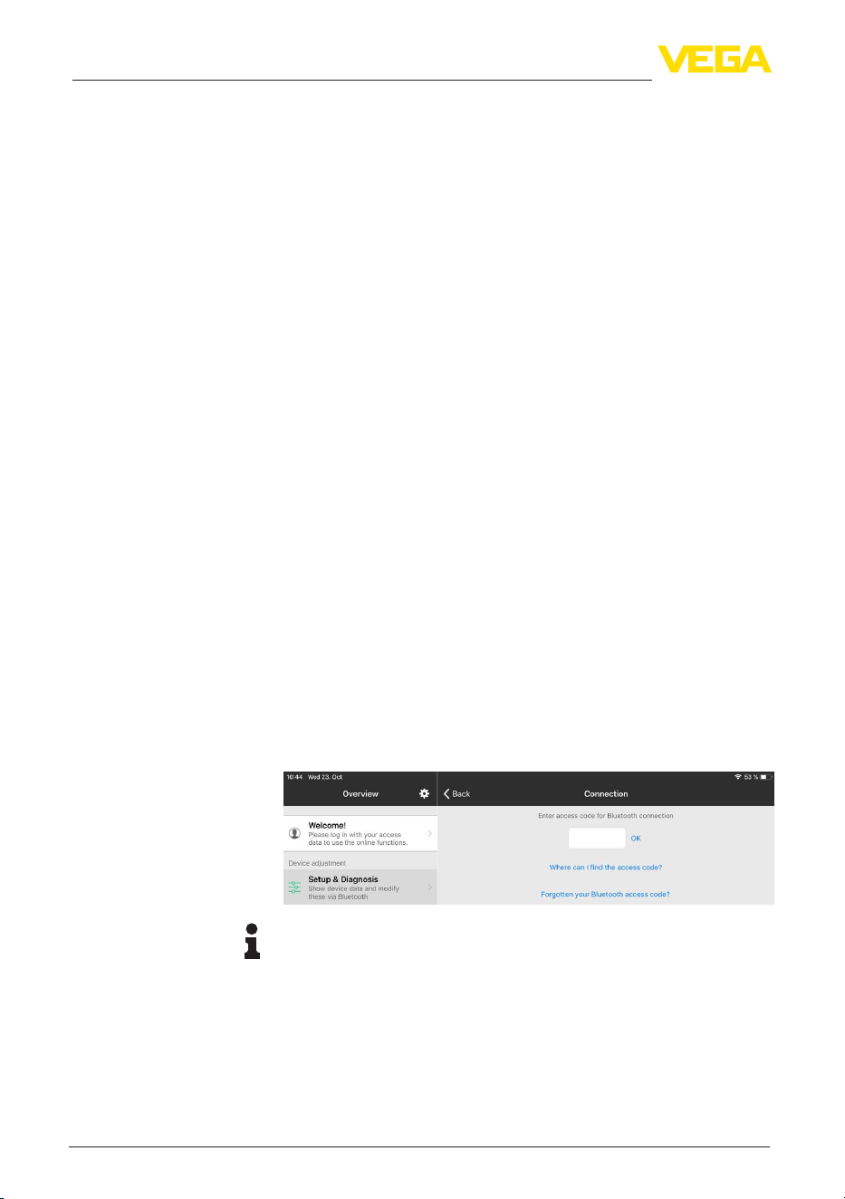
For authentication, enter the 6-digit Bluetooth access code in the
nextmenuwindow.Youcanndthecodeontheoutsideofthedevice
housing and on the information sheet "Pins and Codes" in the device
packaging.
Note:
If an incorrect code is entered, the code can only be entered again
after a delay time. This time gets longer after each incorrect entry.
The message "Waiting for authentication" is displayed on the smart-
phone/tablet.
After connection, the adjustment menu is displayed on the respective
adjustment tool.
System requirements
Connecting
Authenticate
Enter Bluetooth access
code
Connected
29
8 Setup with smartphone/tablet (Bluetooth)
VEGAMET Air 842 • LoRaWAN
1104033-EN-260703
If the Bluetooth connection is interrupted, e.g. due to a too large
distance between the two devices, this is displayed on the adjustment
tool. The message disappears when the connection is restored.
Parameter adjustment of the device is only possible if the parameter
protection is deactivated. When delivered, parameter protection is
deactivated by default and can be activated at any time.
It is recommended to enter a personal 6-digit device code. To do this,
go to menu "Extended functions", "Access protection", menu item
"Protection of the parameter adjustment".
8.3 Parameter adjustment
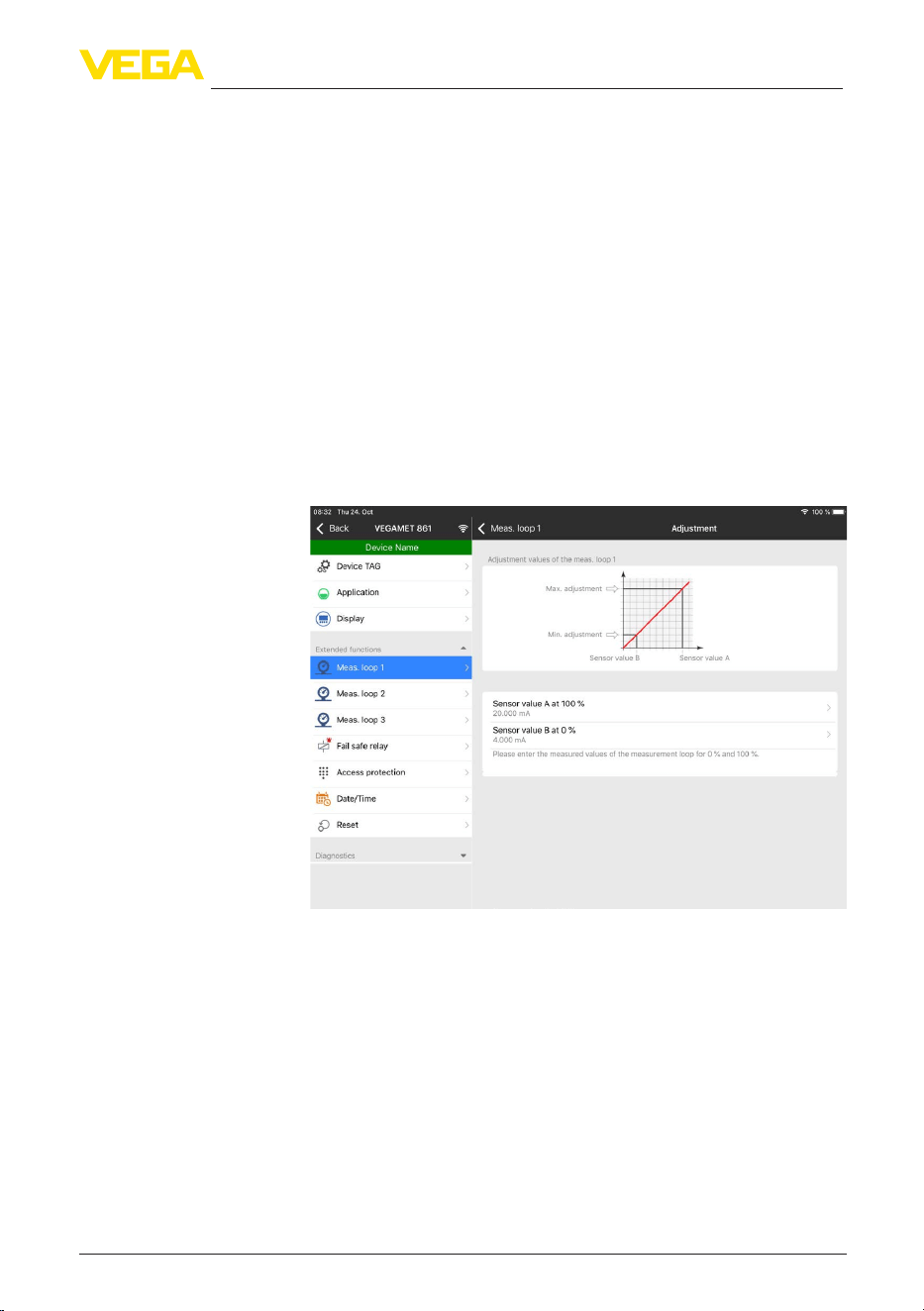
The adjustment menu is divided into two halves:
Ontheleftyouwillndthenavigationareawiththemenus"Setup",
"Extended functions" as well as "Diagnosis".
The selected menu item, recognisable by the colour change, is dis-
played in the right half.
Fig. 10: Example of an app view - Setup adjustment
Entertherequestedparametersandconrmviathekeyboardorthe
editingeld.Thesettingsarethenactiveinthedevice.
Close the app to terminate connection.
Change device code
Enter parameters
30
9 Setup with PC/notebook (Bluetooth)
VEGAMET Air 842 • LoRaWAN
1104033-EN-260703
9 Setup with PC/notebook (Bluetooth)
9.1 Preparations
Make sure that your PC/notebook meets the following system require-
ments:
•
Operating system Windows 10 or newer
•
DTM Collection 10/2020 or newer
•
Bluetooth 4.0 LE or newer
Activate the Bluetooth connection via the project assistant.
Note:
Older systems do not always have an integrated Bluetooth LE. In
these cases, a Bluetooth USB adapter is required. Activate the
Bluetooth USB adapter using the Project Wizard.
After activating the integrated Bluetooth or the Bluetooth USB adapt-
er, devices with Bluetooth are found and created in the project tree.
9.2 Connecting
Select the requested device for the online parameter adjustment in
the project tree.
Whenestablishingtheconnectionforthersttime,theoperatingtool
andthecontrollermustauthenticateeachother.Aftertherstcorrect
authentication, each subsequent connection is made without a new
authentication query.
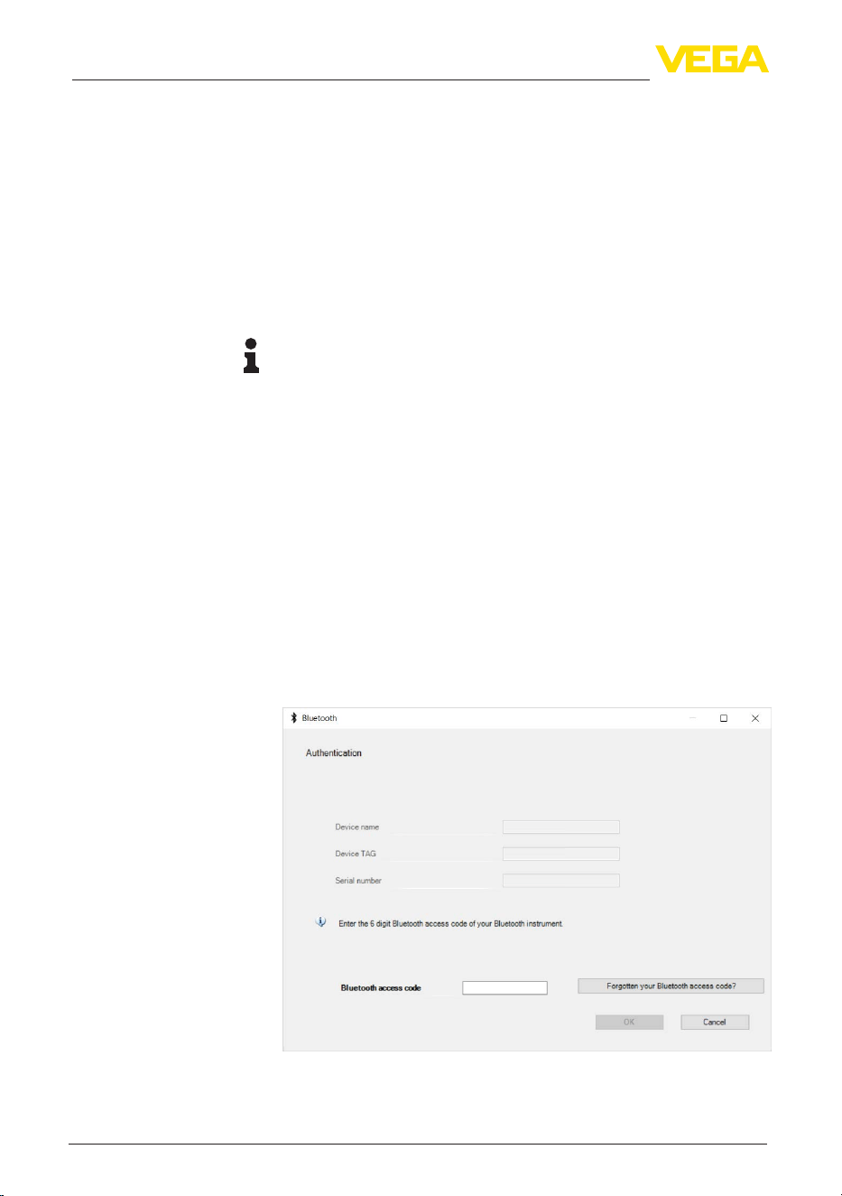
For authentication, enter in the next menu window the 6-digit
Bluetooth access code:
Youcanndthecodeontheinformationsheet"PINs and Codes" in
the device packaging:
System requirements
Activate Bluetooth con-
nection
Connecting
Authenticate
Enter Bluetooth access
code
31
9 Setup with PC/notebook (Bluetooth)
VEGAMET Air 842 • LoRaWAN
1104033-EN-260703
Note:
If an incorrect code is entered, the code can only be entered again
after a delay time. This time gets longer after each incorrect entry.
The message "Waiting for authentication" is displayed on the PC.
After connection, the DTM appears.
If the connection is interrupted, e.g. due to a too large distance
between controller and PC, this is displayed on the PC. The message
disappears when the connection is restored.
Parameter adjustment of the device is only possible if the parameter
protection is deactivated. When delivered, parameter protection is
deactivated by default and can be activated at any time.
It is recommended to enter a personal 6-digit device code. To do this,
go to menu "Extended functions", "Access protection", menu item
"Protection of the parameter adjustment".
9.3 Parameter adjustment
For parameter adjustment of the instrument via a Windows PC, the
congurationsoftwarePACTwareandasuitableinstrumentdriver
(DTM) according to FDT standard are required. The latest PACTware
version as well as all available DTMs are compiled in a DTM Collec-
tion. The DTMs can also be integrated into other frame applications
according to FDT standard.
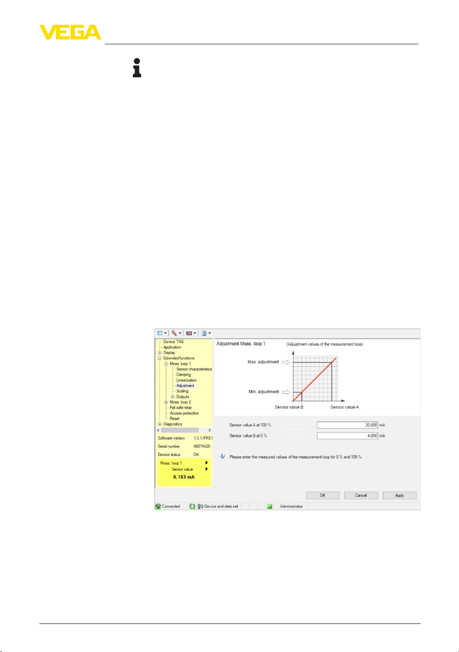
Fig. 11: Example of a DTM view - Adjustment
Connected
Change device code
Prerequisites

32
10 Applications and functions
VEGAMET Air 842 • LoRaWAN
1104033-EN-260703
10 Applications and functions
The controller contains already preset applications and functions,
which can be easily adjusted by means of an application assistant via
PACTware/DTM or the VEGA Tools app. The following applications/
functions are described here as examples.
•
Levelmeasurementinstoragetankswithoverllprotection/dryrun
protection
•
Pump station with pump control function
•
Screen control
•
Flowmeasurementume/weir
10.1 Application example
ToDo

33
11 Diagnostics and servicing
VEGAMET Air 842 • LoRaWAN
1104033-EN-260703
11 Diagnostics and servicing
11.1 Maintenance
If the device is used properly, no special maintenance is required in
normal operation.
The cleaning helps that the type label and markings on the instrument
are visible.
Take note of the following:
•
Use only cleaning agents that do not damage the housing, type
plate or seals, e.g. a cloth dampened with water
•
Use only cleaning methods corresponding to the housing protec-
tion rating
11.2 Rectify faults
The operator of the system is responsible for taking suitable meas-
ures to rectify faults.
Thedeviceoersmaximumreliability.Nevertheless,faultscanoccur
during operation. These may be caused by the following, e.g.:
•
Measured value from sensor not correct
•
Voltage supply
•
Interference in the cables
Therstmeasuresare:
•
Evaluation of fault messages
•
Checking the input/output signal
A smartphone/tablet with the VEGA Tools app or a PC/notebook with
thesoftwarePACTwareandthesuitableDTMoeryoufurthercom-
prehensive diagnostic possibilities. In many cases, the causes can be
determined in this way and the malfunctions eliminated.
Depending on the reason for the fault and the measures taken, the
steps described in chapter "Setup" must be carried out again or must
be checked for plausibility and completeness.
Should these measures not be successful, please call in urgent cases
the VEGA service hotline under the phone no. +49 1805 858550.
The hotline is also available outside normal working hours, seven
days a week around the clock.
Sinceweoerthisserviceworldwide,thesupportisprovidedin
English. The service itself is free of charge, the only costs involved are
the normal call charges.
11.3 Diagnosis, fault messages
The controller and the connected sensors are permanently monitored
during operation and the values entered during parameter adjust-
ment are checked for plausibility. If irregularities occur or in case of
Maintenance
Cleaning
Reaction when malfunc-
tion occurs
Causes of malfunction
Faultrectication
Reaction after fault recti-
cation
24 hour service hotline
Fault signal
34
11 Diagnostics and servicing
VEGAMET Air 842 • LoRaWAN
1104033-EN-260703
incorrect parameter adjustment, a fault signal is triggered. In case of
an instrument defect and a failed data transfer, a fault signal is also
triggered.
The fault indication lights up in case of failure and the current output
aswellastherelaysreactaccordingtotheconguredfaultmode.If
thefailsaferelaywascongured,itwilldeenergize.Inaddition,one
of the following error messages is outputted on the display and the
background lighting changes to colour acc. to NAMUR NE 107 (e.g.
red in case of a fault, orange in case of a function check).
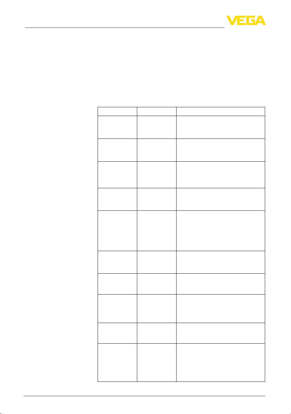
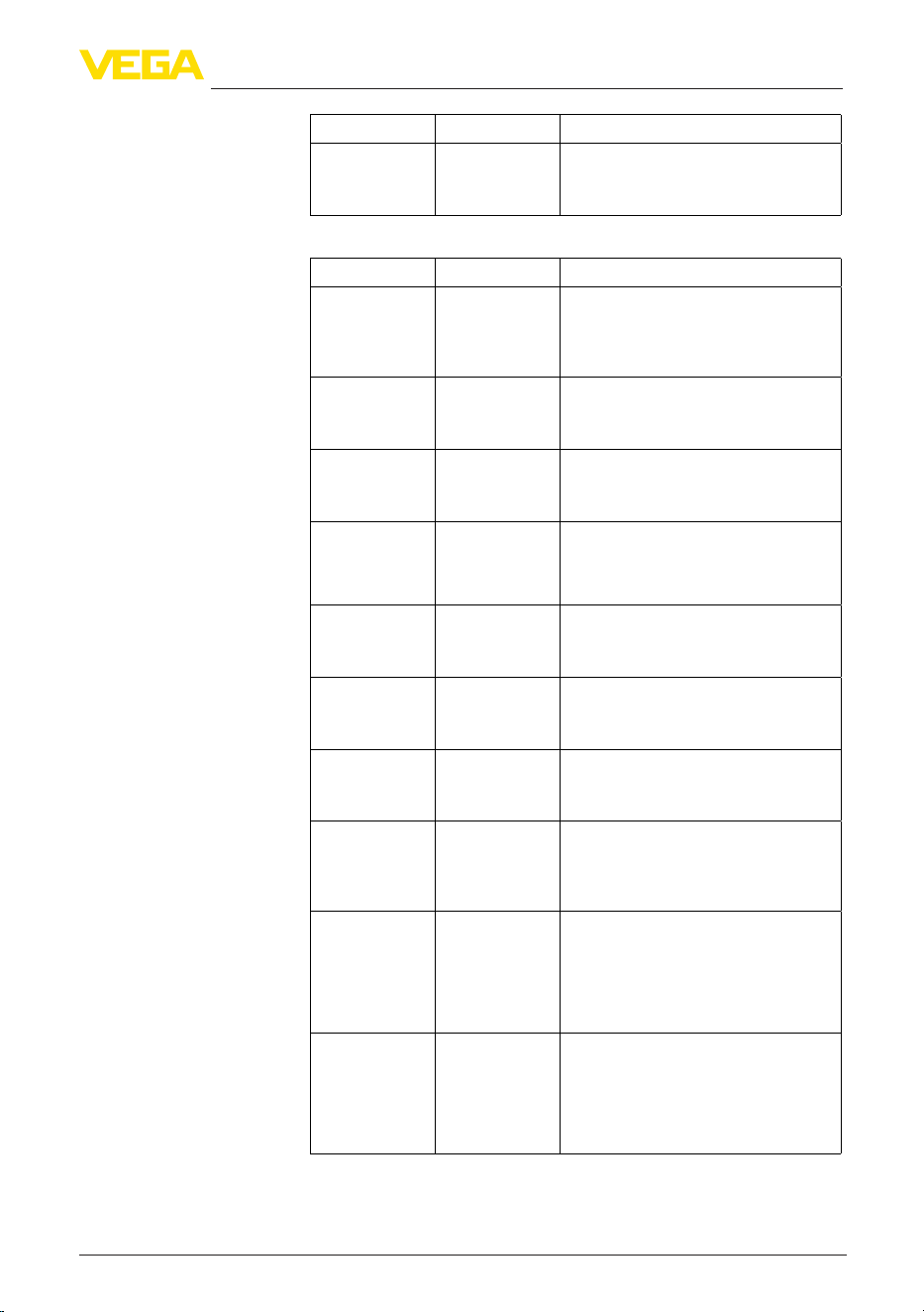
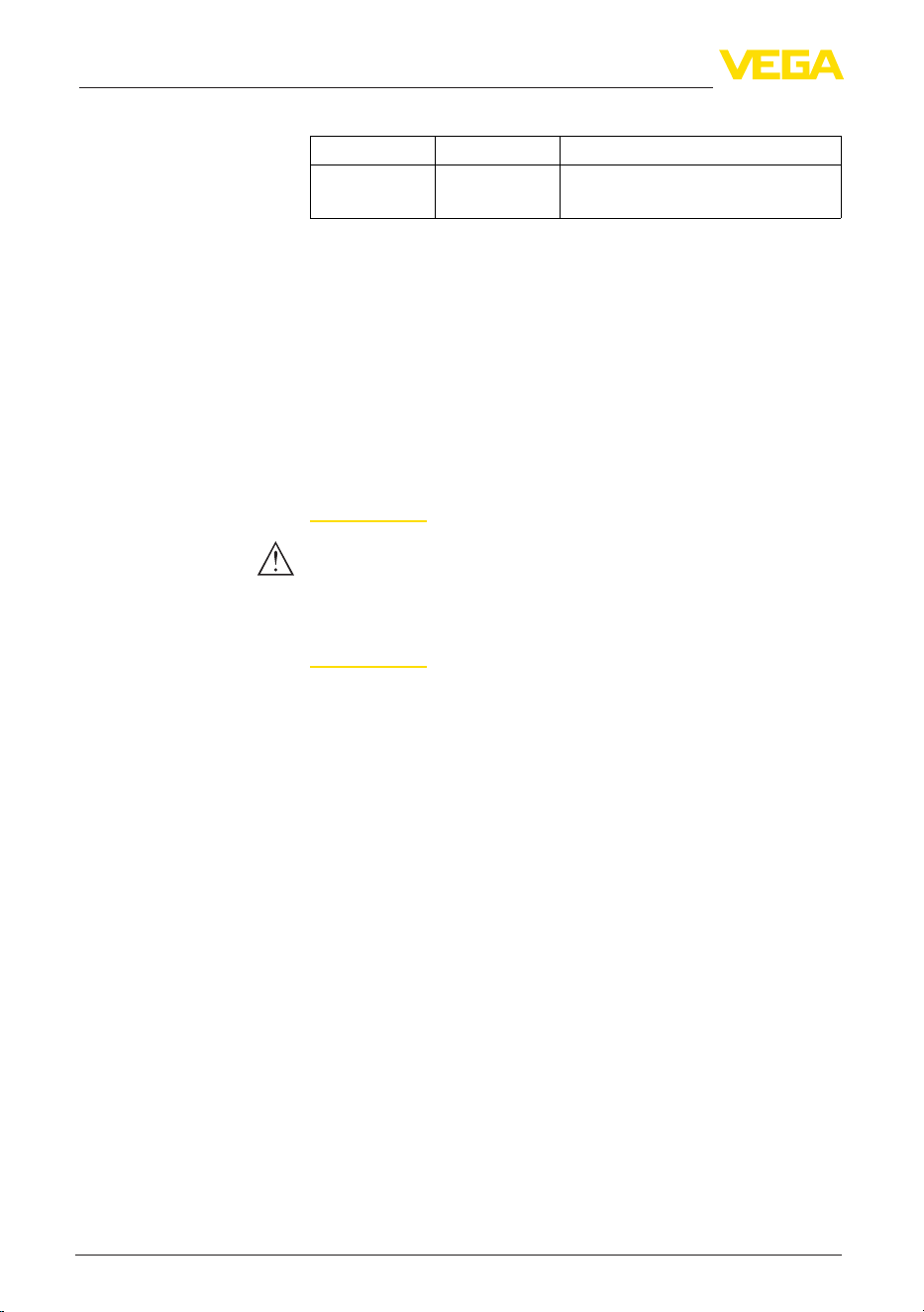
Error code Cause Rectication
F002
no measuring
pointcongured
Measuring point
was not yet con-
gured
No sensor assigned.
For measuring point 3: No application
with 3 measuring points was selected.
F003
Hardware: CRC
error
CRC error (error
with self-check)
Switchtheinstrumento/on
Carry out a reset
Send instrument for repair
F008
Sensor not ac-
cessible
No sensor da-
ta has been
received for
some time
Reduce distance to the sensor
Use external antenna
Exchange battery in the sensor
F012
Sensor input:
Hardware error
Hardware error,
sensor input
Switchtheinstrumentoandon
Send instrument for repair
F013
Sensor input:
Sensor error
The input of the
measuring point
returns an error
The connected
sensor returns
an error
Switchdevice/sensoroanon
Send device/sensor for repair
F034
EEPROM: CRC
error
EEPROM: CRC
error
Switchtheinstrumentoandon
Carry out a reset
Send instrument for repair
F035
ROM: CRC error
ROM: CRC error Switchtheinstrumentoandon
Carry out a reset
Send instrument for repair
F036
No operable
software
No executable
program
Software update
failed
Carry out another software update
Send instrument for repair
F037
RAM
RAM defective Switchtheinstrumentoandon
Carry out a reset
Send instrument for repair
F039
No join within 24
hours
No join request
was received
from the sensor
24 hours after
the NFC/DTM
pairing
Place the sensor next to VEGAMET Air
842 and perform a manual join on the
sensor
Failure
35
11 Diagnostics and servicing
VEGAMET Air 842 • LoRaWAN
1104033-EN-260703
Error code Cause Rectication
F040
General hard-
ware error
Hardware error Switchtheinstrumentoandon
Carry out a reset
Send instrument for repair
Error code Cause Rectication
S016
Adjustment:
Min./Max. ex-
changed
The min./max.
adjustment
points were ex-
changed.
Carry out the adjustment again, correct
the min. and max. values.
S017
Adjustment:
Span too small
Adjustment span
too small
Carry out a fresh adjustment and in-
crease the distance between min./max.
adjustment
S021
Scaling: Span
too small
Scaling span too
small
Carry out a fresh scaling, increase the
distance between min./max. scaling.
S022
Scaling: Scaling
value too large
Value for one
of the two scal-
ing points is too
large
Carry out the scaling again, correct the
min. and max. values.
S062
Pulse priority too
small
Pulse priority too
small
Increase under "Output" the entry
"Pulse output all" so that max. one pulse
per second is output.
S104
Measurement
loop deactivated
The measuring
point is deacti-
vated
Activate measuring point
S110
Relay: Span too
small
Relay switching
points too close
together
Increasethedierencebetweenthetwo
relay switching points
S111
Relay: Switching
points inter-
changed
Relay switching
points inter-
changed
Change relay switching points for "On/
O"
S115
Pump control:
Faulty interfer-
ence behaviour
Several relays
are assignef to
the pump control
which are not set
to the same fail-
ure mode
All relays which are assigned to the
pump control must be set to the same
failure mode
S116
Pump control:
Operating mode
faulty
Several relays
that are not con-
guredwiththe
same mode are
assigned to the
pump control
All relays which are assigned to the
pump control must be set to the same
mode
Outofspecication
36
11 Diagnostics and servicing
VEGAMET Air 842 • LoRaWAN
1104033-EN-260703
Error code Cause Rectication
C029
Simulation
Simulation active Finish simulation
11.4 Software update
An update of the device software is possible via the Bluetooth inter-
face.
The following components are required:
•
Instrument
•
Voltage supply
•
PC/Notebook with PACTware/DTM
•
Currentinstrumentsoftwareasle
Youcanndthecurrentinstrumentsoftwareaswellasdetailed
information on the procedure in the download area of our homepage:
www.vega.com.
Caution:
Instruments with approvals can be bound to certain software versions.
Thereforemakesurethattheapprovalisstilleectiveafterasoftware
update is carried out.
Youcannddetailedinformationinthedownloadareaat
www.vega.com.
11.5 How to proceed if a repair is necessary
Onourhomepageyouwillnddetailedinformationonhowtopro-
ceed in the event of a repair.
So that we can carry out the repair quickly and without queries, gen-
erate a instrument return form there with the data of your device.
The following is required:
•
The serial number of the instrument
•
A short description of the fault
•
Where applicable, details of the medium and process conditions
Print the generated instrument return form.
Clean the instrument and pack it damage-proof.
Send the printed instrument return form and possibly a safety data
sheet together with the device.
Youwillndtheaddressforthereturnonthegeneratedinstrument
return form.
Function check

37
12 Dismount
VEGAMET Air 842 • LoRaWAN
1104033-EN-260703
12 Dismount
12.1 Dismounting steps
Take note of chapters "Mounting" and "Connecting to voltage supply"
and carry out the listed steps in reverse order.
12.2 Disposal
Pass the instrument on to a specialised recycling company and do not
use the municipal collecting points.
Remove any batteries in advance, if they can be removed from the
device, and dispose of them separately.
If personal data is stored on the old device to be disposed of, delete it
before disposal.
If you have no way to dispose of the old instrument properly, please
contact us concerning return and disposal.

38
13Certicatesandapprovals
VEGAMET Air 842 • LoRaWAN
1104033-EN-260703
13 Certicatesandapprovals
13.1 Radio licenses
Bluetooth
The Bluetooth radio module in the device has been tested and
approved according to the current edition of the applicable country-
specicnormsorstandards.
Theconrmationsaswellasregulationsforusecanbefoundinthe
document "Radio licenses" supplied or on our homepage.
LoRaWAN
The radio module in the device has been tested and approved ac-
cordingtothecurrenteditionoftheapplicablecountry-specicnorms
or standards.
Theconrmationsaswellasregulationsforusecanbefoundinthe
document "Radio licenses" supplied or on our homepage.
NFC
The radio module in the device has been tested and approved ac-
cordingtothecurrenteditionoftheapplicablecountry-specicnorms
or standards.
Theconrmationsaswellasregulationsforusecanbefoundinthe
document "Radio licenses" supplied or on our homepage.
13.2 Conformity
The device complies with the legal requirements of the applicable
country-specicdirectivesortechnicalregulations.Weconrmcon-
formity with the corresponding labelling.
The corresponding conformity declarations can be found on our
homepage.
Electromagnetic compatibility
The instrument is designed for use in an industrial environment.
Nevertheless, electromagnetic interference from electrical conductors
and radiated emissions must be taken into account, as is usual with a
class A instrument according to EN 61326-1. If the instrument is used
inadierentenvironment,itselectromagneticcompatibilitywithother
devices must be ensured by suitable measures.
13.3 Environment management system
Protection of the environment is one of our most important duties.
That is why we have introduced an environment management system
with the goal of continuously improving company environmental pro-
tection.Theenvironmentmanagementsystemiscertiedaccording
to DIN EN ISO 14001.
Help us to meet these requirements and observe the environmental
instructions in the chapters "Packaging, transport and storage", "Dis-
posal" of this instructions manual.
39
14 Supplement
VEGAMET Air 842 • LoRaWAN
1104033-EN-260703
14 Supplement
14.1 Technical data
Note for approved instruments
The technical data in the respective safety instructions are valid for approved instruments (e.g. with
Exapproval).Insomecases,thesedatacandierfromthedatalistedherein.
All approval documents can be downloaded from our homepage.
Materials and weights
Materials
Ʋ Housing PC-FR
Ʋ Housing screws StSt
Ʋ Inspection window PE
Ʋ Seal Silicone
Ʋ Cable glands PA
Ʋ Sun shade 316L
Ʋ Brackets for tube mounting StSt
Weight with mounting plate 890 g (1.962 lbs)
Voltage supply
Operating voltage
Ʋ Nominal voltage AC 100…230V∿(-15%,+10%)50/60Hz
Ʋ Nominal voltage DC 24 … 65 V = (-15 %, +10 %)
Power consumption max. 18 VA; 7 W
Sensor input
Number of sensors 2 x wireless sensor
Measured value transmission LoRaWAN
Relay output
Quantity 3xoperatingrelay,onecanbeconguredasfailsafe
relay
Function Switching relay for level, fault signal or pulse relay for
ow/samplingpulse,pumpcontrol
Contact Floating change-over contact (SPDT)
Contact material AgSnO2, hard gold-plated
Switching voltage max. 250 V AC/60 V DC
Switching current max. 1 A AC (cos phi > 0.9), 1 A DC

40
14 Supplement
VEGAMET Air 842 • LoRaWAN
1104033-EN-260703
Breaking capacity
2)
min. 50 mW, max. 250 VA, max. 40 W DC (with
U < 40 V DC)
AC/DC operation Mixed operation with hazardous voltages (> 30 V AC,
> 60 V DC) and non-hazardous voltages (< 30 V AC,
< 60 V DC) is not permitted for the relay outputs.
Min. programmable switching hysteresis 0.1 %
Mode pulse output
Ʋ Pulse length 350 ms
Current output
Quantity 2 x output
Function Level/ow/samplingpulse
Range 0/4 … 20 mA, 20 … 0/4 mA
Resolution 1 µA
Max. load 500Ω
Fault signal (switch over) 0; < 3.6; 4; 20; 20.5; 22 mA
Accuracy
Ʋ Standard ±20 µA (0.1 % of 20 mA)
Ʋ with EMC interferences ±80 µA (0.4 % of 20 mA)
Temperature error relating to 20 mA 0.005 %/K
Mode pulse output
Ʋ Current pulse 20 mA
Ʋ Pulse length 200 ms
LoRaWAN
Eectiverange
3)
up to 15 km (9,3 mi)
External antenna
Ʋ Omnidirectionaldipoleantennatted
directly to the device (included in
delivery)
3.5 dBi (863 MHz … 870 MHz), 3.84 dBi (902
MHz … 928 MHz)
Ʋ Antenna gain < 4 dBi
Ʋ Antenna connection RPSMA(F)
LoRaWAN region EU863-870, US902-928, AU915-928, AS923-1
Frequencies
Ʋ EU868 863 MHz … 870 MHz
Ʋ US915 902 MHz … 928 MHz
2)
If inductive loads or stronger currents are switched through, the gold plating on the relay contact surface will be
permanently damaged. The contact is then no longer suitable for switching low-level signal circuits.
3)
Depending on the local conditions

41
14 Supplement
VEGAMET Air 842 • LoRaWAN
1104033-EN-260703
Ʋ IN865 865 MHz … 867 MHz
Ʋ RU864 864 MHz … 870 MHz
Ʋ AU915 915 MHz … 928 MHz
Ʋ AS923 915 MHz … 928 MHz
Ʋ KR920 920.9 MHz … 923.3 MHz
Max. emitted power
Ʋ EU863-870 14 dBm
Ʋ US902-928 26 dBm
Ʋ AU915-928 26 dBm
Ʋ AS923-1 16 dBm
Ʋ IN865 26 dBm
Ʋ RU864 14 dBm
LoRaWANSpecicationVersion V1.0.4
LoRaWAN Regional Parameters Version RP002-1.0.4
Class of Operation A
Optional ADR Feature Supported Yes
Activation OTAA
Bluetooth interface
Bluetooth standard Bluetooth 5.0
Frequency 2.402 … 2.480 GHz
Antenna Internal
Max. emitted power +2.2 dBm
Max. number of participants 1
Eectiverange
4)
up to 50 m (164 ft)
NFC reader
Frequency 13.56 MHz
Transmission power < 60 dBµA/m
Antenna Integrated loop
Eectiverange typically 4 cm (1.5 in)
Electromechanical data
Cable entry
Ʋ Cable gland (optional) M20 x 1.5 (cable diameter 6 … 12 mm), torque 4.5 Nm
Ʋ NPT adapter (optional) M20 on ½ NPT
Ʋ Blind plug (optional) M20 x 1.5
Connection terminals
Ʋ Type of terminal Spring-loaded terminal
4)
Depending on the local conditions
42
14 Supplement
VEGAMET Air 842 • LoRaWAN
1104033-EN-260703
Ʋ Wire cross-section massive wire,
strand
0.2 mm² (AWG 26) … 2.5 mm² (AWG 12)
Ʋ Wire cross-section strand with end
sleeve
0.25 mm² … 1.5 mm²
Indicators
Measured value indication
Ʋ Graphic-capable LC display, with
lighting
89 x 56 mm, digital and quasianalogue display
Ʋ Indication range -9999999 … 9999999
LED displays
Ʋ Status, operating voltage LED green
Ʋ Status fault signal LED red
Ʋ Status, operating relay LED yellow
Status display via backlight Colour signalling according to NAMUR NE 107 (red/
orange/yellow/blue)orfreelycongurable
Adjustment
Adjustment elements 4 x keys for menu adjustment
PC/Notebook PACTware/DTM
Smartphone/Tablet VEGA Tools app
Ambient conditions
Ambient temperature
Ʋ Instrument in general -40…+60°C(-40…+140°F)
Ʋ Display (readability) -20…+60°C(-4…+140°F)
Storage and transport temperature -40…+80°C(-40…+176°F)
Relative humidity < 96 %
Mechanical environmental conditions
Vibrations (oscillations) Class 4M8 acc. to IEC 60721-3-4 (5 g, 4 … 200 Hz)
Impacts (mechanical shock) Class 6M4 acc. to IEC 60721-3-6 (10 g/11 ms,
30 g/6 ms, 50 g/2.3 ms)
Electrical protective measures
Protection rating IP66/IP67 acc. to IEC 60529, Type 4X acc. to UL 50
Altitude above sea level up to 5000 m (16404 ft)
Overvoltage category (IEC 61010-1) II
Protection class I
Pollution degree 4
Protection against dangerous body currents
Reliable separation according to IEC/EN 61140 by reinforced insulation according to IEC/
EN61010part1upto253VAC/DCwithovervoltagecategoryIIandfullledprotectionclass
between the supply, signal and relay circuits.
43
14 Supplement
VEGAMET Air 842 • LoRaWAN
1104033-EN-260703
Sensor inputs (active) are energy limited circuits according to IEC/UL 61010 part 1.
14.2 Overview applications/functionality
The following charts provide an overview of the standard applications and functions of VEGAMET
Air series controllers. They give also information about whether the respective function can be acti-
vated and adjusted via the integrated indicating and adjustment unit (OP) or via DTM/app.
5)
Applications (adjustable with DTM/app) VEGAMET Air Adjustment
141
841
142
842
OP DTM/
App
Universal • • • •
Level - storage tank • • •
Calculation-dierence • •
Calculation - total • •
Calculation - average value • •
Wells • • •
Pumping station • • •
Sewage screw lifting station • • •
Screen control • •
Flowmeasurementume/weir • • •
Pressurized vessel • •
Additional application examples VEGAMET Air Adjustment
141
841
142
842
OP DTM/
App
Level measurement • • •
Gauge measurement • • •
Process pressure measurement • • •
Overowbasin • •
Density • •
Functions VEGAMET Air Adjustment
141
841
142
842
OP DTM/
App
Application wizard • • •
Indication measured values • • • •
Automatic display change • • • •
Display multilingual • • • •
Sensor input 4 … 20 mA • • • •
5)
OP: Operating Panel (integrated display and adjustment unit)
44
14 Supplement
VEGAMET Air 842 • LoRaWAN
1104033-EN-260703
Functions VEGAMET Air Adjustment
141
841
142
842
OP DTM/
App
Linearization - preset curves • • • •
Linearization - Dimensions ISO standard • • •
Linearization - Flow formula • • •
Linearization-Manufacturerdenition • • •
Linearization - Calculation wizard • • •
Linearization - Bearing table • • •
Linearization - Gauging by litres • • •
Linearization curves - Import • • •
Adjustment of the measuring point • • • •
Scaling • • • •
Totalizer 1/2 • • • •
Totalizer 3/4/5/6 • •
Relaymode-Overllprotection • • • •
Relay mode - Dry run protection • • • •
Relay mode - Switching window ON • • •
Relay mode - Switching window OFF • • •
Relay mode - Flow rate pulse • • •
Relay mode - Sampling pulse • • •
Relay mode - Rising tendency • • •
Relay mode - Falling tendency • • •
Relay mode - Pump control 1 (same running time) • • •
Relay mode - Pump control 2 (same running time) • • •
Relaymode-Pumpcontrol3(xedsequence) • • •
Relaymode-Pumpcontrol4(xedsequence) • • •
Mode - Pump control - Sequenced operation • • •
Mode - Pump control - Alternating pump operation • • •
Dry weather pump • • •
Forced pump changeover • • •
Relayswitchonandodelay • • •
Bandwidth for switching points • • •
Fail safe relay • • • •
Current output - 0/4 … 20 mA, 20 … 4 mA • • • •
Current output - Flow rate pulse • • •
Current output - Sampling pulse • • •
Diagnosis - Status • • • •
Diagnosis - Measured values • • • •
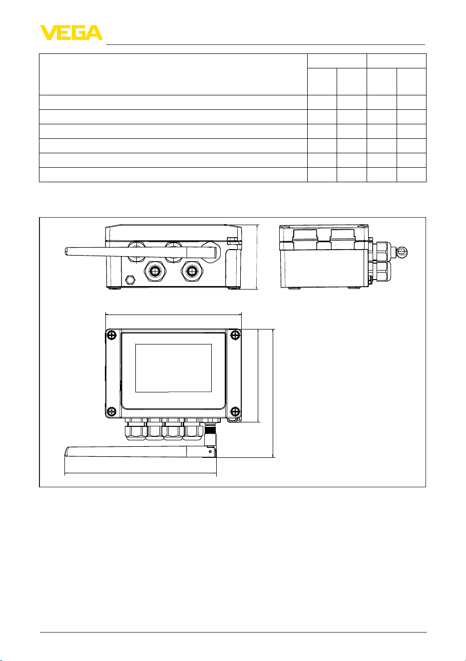
45
14 Supplement
VEGAMET Air 842 • LoRaWAN
1104033-EN-260703
Functions VEGAMET Air Adjustment
141
841
142
842
OP DTM/
App
Simulation - Sensor value, %, lin% value, scaled values • • • •
Simulation - current output • • •
Simulation - relay output • • •
Protection of the parameterization • • • •
Bluetooth access code • • • •
Activate/deactivate Bluetooth communication • • •
14.3 Dimensions
162 mm
(6.38")
180 mm
(7.09")
76 mm
(2.99")
11 1 mm
(4.37")
153 mm
(6.02")
Fig. 12: Dimensions VEGAMET Air 842
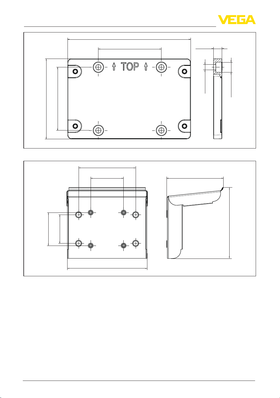
46
14 Supplement
VEGAMET Air 842 • LoRaWAN
1104033-EN-260703
82 mm
(3.23")
11 mm
(0.43")
160 mm
(6.30")
82 mm
(3.23")
104 mm
(4.09")
ø13 mm
(0.51")
ø7 mm
(0.27")
Fig. 13: Dimensions mounting plate
82 mm
(3.23")
142 mm
(5.59")
198 mm
(7.80")
71 mm
(2.76")
82 mm
(3.23")
ca. 141 mm
(5.55")
ca. 177 mm
(6.97")
Fig. 14: Dimensions sun shade
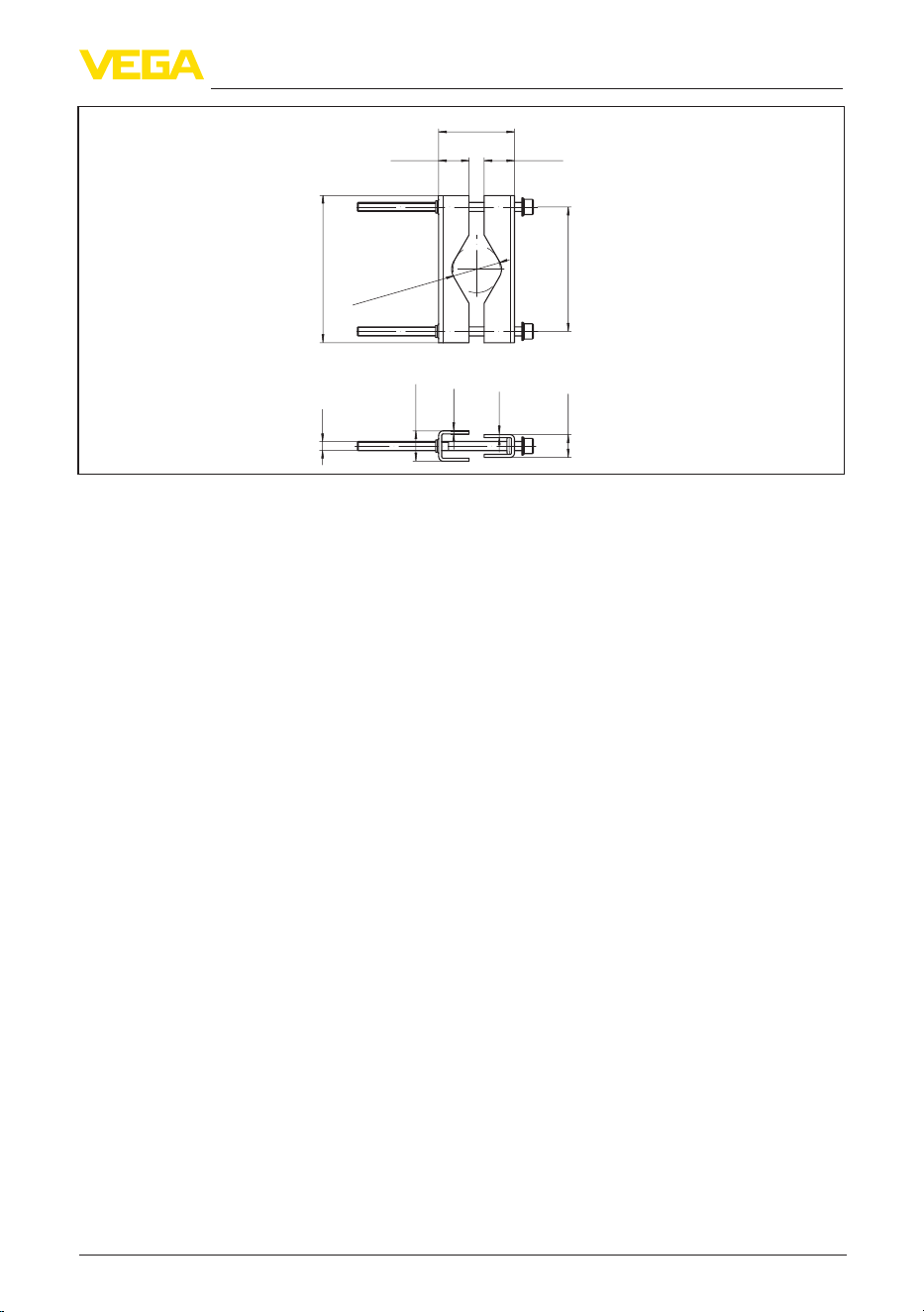
47
14 Supplement
VEGAMET Air 842 • LoRaWAN
1104033-EN-260703
ø 29...60 mm
(1.14"...2.36")
82 mm
(3.23")
15 mm
(0.59")
97 mm
(3.82")
20 mm
(0.79")
M6
2 mm
(0.08")
20 mm
(0.79")
2 mm
(0.08")
20 mm
(0.79")
48...84 mm
(1.89"...3.31")
Fig. 15: Dimensions Brackets for tube mounting

48
14 Supplement
VEGAMET Air 842 • LoRaWAN
1104033-EN-260703
14.4 Industrial property rights
VEGA product lines are global protected by industrial property rights. Further information see
www.vega.com.
VEGA Produktfamilien sind weltweit geschützt durch gewerbliche Schutzrechte.
Nähere Informationen unter www.vega.com.
Les lignes de produits VEGA sont globalement protégées par des droits de propriété intellec-
tuelle. Pour plus d'informations, on pourra se référer au site www.vega.com.
VEGA lineas de productos están protegidas por los derechos en el campo de la propiedad indus-
trial. Para mayor información revise la pagina web www.vega.com.
Линии продукции фирмы ВЕГА защищаются по всему миру правами на интеллектуальную
собственность. Дальнейшую информацию смотрите на сайте www.vega.com.
VEGA系列产品在全球享有知识产权保护。
进一步信息请参见网站<www.vega.com。
14.5 Licensing information for open source software
Open source software components are also used in this device. A documentation of these compo-
nents with the respective license type, the associated license texts, copyright notes and disclaimers
can be found on our homepage.
14.6 Trademark
All the brands as well as trade and company names used are property of their lawful proprietor/
originator.
49
Notes
VEGAMET Air 842 • LoRaWAN
1104033-EN-260703

50
Notes
VEGAMET Air 842 • LoRaWAN
1104033-EN-260703
51
Notes
VEGAMET Air 842 • LoRaWAN
1104033-EN-260703

Printing date:
VEGA Grieshaber KG
Am Hohenstein 113
77761 Schiltach
Germany
1104033-EN-260703
All statements concerning scope of delivery, application, practical use and operat-
ing conditions of the sensors and processing systems correspond to the information
available at the time of printing.
Subject to change without prior notice
© VEGA Grieshaber KG, Schiltach/Germany 2026
Phone +49 7836 50-0
E-mail: [email protected]
www.vega.com
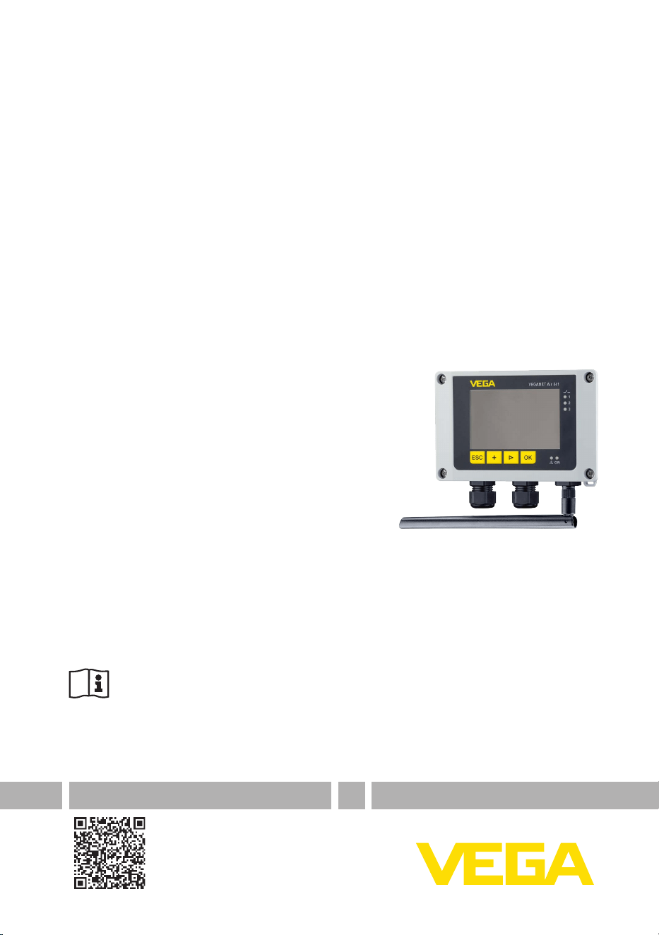
Operating Instructions
Controller in a eld housing for
connecting of a radio-based sensor
VEGAMET Air 841
LoRaWAN
Document ID: 1104032

2
Contents
VEGAMET Air 841 • LoRaWAN
1104032-EN-260703
Contents
1 About this document ............................................................................................................... 4
1.1 Function ........................................................................................................................... 4
1.2 Target group ..................................................................................................................... 4
1.3 Symbols used................................................................................................................... 4
2 For your safety ......................................................................................................................... 5
2.1 Authorised personnel ....................................................................................................... 5
2.2 Intended use .................................................................................................................... 5
2.3 Warning about incorrect use ............................................................................................. 5
2.4 General safety instructions ............................................................................................... 5
2.5 Installation and operation in the USA and Canada ........................................................... 6
2.6 Safety instructions for Ex areas ........................................................................................ 6
3 Product description ................................................................................................................. 7
3.1 Conguration .................................................................................................................... 7
3.2 Principle of operation........................................................................................................ 8
3.3 Adjustment ....................................................................................................................... 9
3.4 Packaging, transport and storage ................................................................................... 10
3.5 Accessories.................................................................................................................... 10
4 Mounting ................................................................................................................................. 11
4.1 General instructions ....................................................................................................... 11
4.2 Mounting instructions ..................................................................................................... 12
5 Connecting to power supply ................................................................................................. 14
5.1 Preparing the connection ............................................................................................... 14
5.2 Connecting ..................................................................................................................... 15
5.3 Wiring plan ..................................................................................................................... 15
5.4 Switch-on phase............................................................................................................. 16
6 Access protection .................................................................................................................. 17
6.1 Bluetooth radio interface ................................................................................................ 17
6.2 Protection of the parameterization .................................................................................. 17
6.3 Storing the codes in myVEGA ........................................................................................ 18
7 Set up with the integrated display and adjustment unit .................................................... 19
7.1 Adjustment system ......................................................................................................... 19
7.2 Measured value and menu item display ......................................................................... 20
7.3 Menu overview ............................................................................................................... 21
7.4 Setup steps .................................................................................................................... 22
8 Setup with smartphone/tablet (Bluetooth) .......................................................................... 27
8.1 Preparations ................................................................................................................... 27
8.2 Connecting ..................................................................................................................... 27
8.3 Parameter adjustment .................................................................................................... 28
9 Setup with PC/notebook (Bluetooth) ................................................................................... 29
9.1 Preparations ................................................................................................................... 29
9.2 Connecting ..................................................................................................................... 29
9.3 Parameter adjustment .................................................................................................... 30
10 Applications and functions ................................................................................................... 31
10.1 Application example ....................................................................................................... 31
11 Diagnostics and servicing .................................................................................................... 32

3
Contents
VEGAMET Air 841 • LoRaWAN
1104032-EN-260703
11.1 Maintenance .................................................................................................................. 32
11.2 Rectify faults ................................................................................................................... 32
11.3 Diagnosis, fault messages ............................................................................................. 32
11.4 Software update ............................................................................................................. 34
11.5 How to proceed if a repair is necessary .......................................................................... 35
12 Dismount................................................................................................................................. 36
12.1 Dismounting steps.......................................................................................................... 36
12.2 Disposal ......................................................................................................................... 36
13 Certicatesandapprovals .................................................................................................... 37
13.1 Radio licenses ................................................................................................................ 37
13.2 Conformity ...................................................................................................................... 37
13.3 Environment management system ................................................................................. 37
14 Supplement ............................................................................................................................ 38
14.1 Technical data ................................................................................................................ 38
14.2 Overview applications/functionality ................................................................................ 42
14.3 Dimensions .................................................................................................................... 44
14.4 Industrial property rights ................................................................................................. 47
14.5 Licensing information for open source software ............................................................. 47
14.6 Trademark ...................................................................................................................... 47
Editing status: 2026-04-07
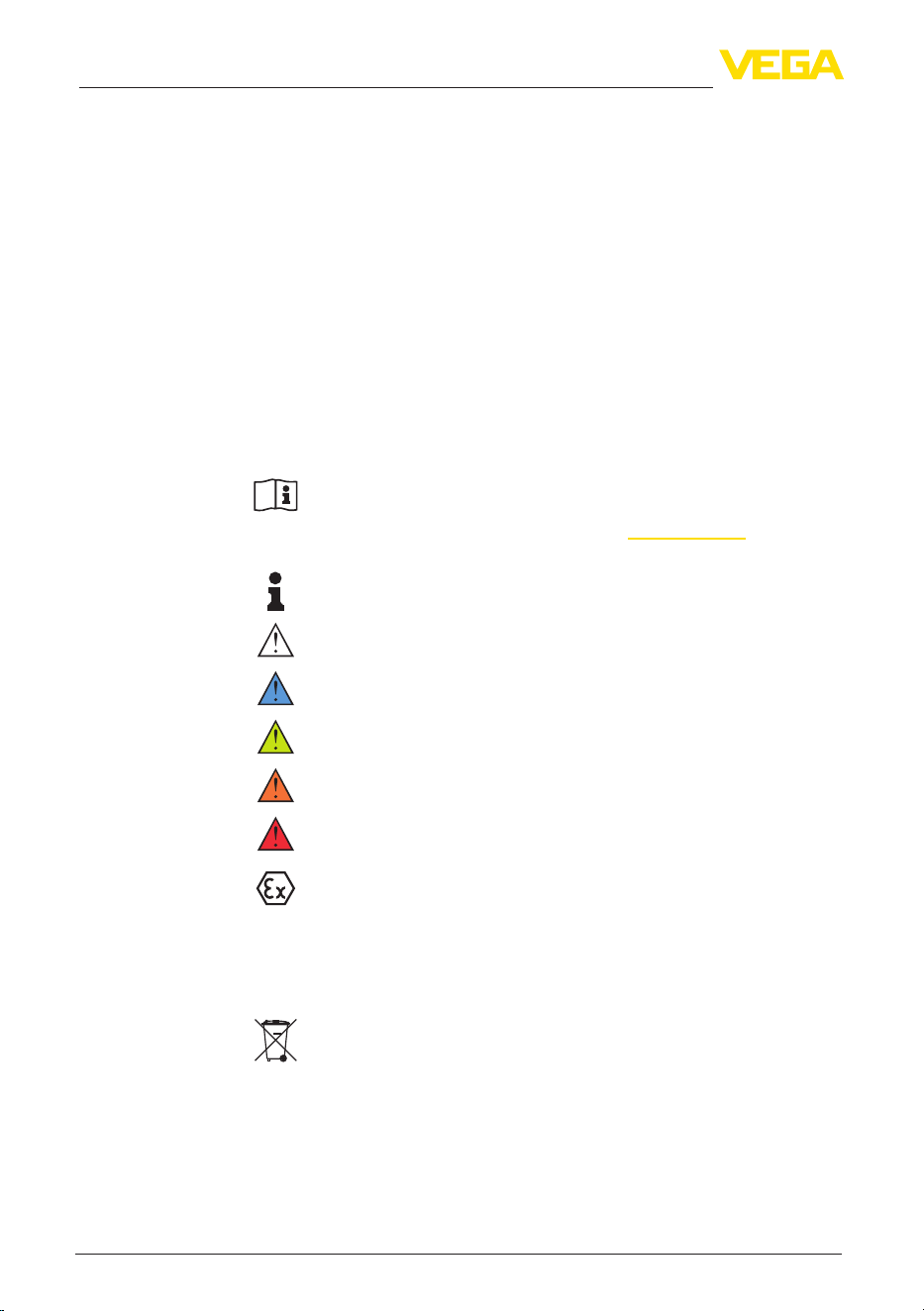
4
1 About this document
VEGAMET Air 841 • LoRaWAN
1104032-EN-260703
1 About this document
1.1 Function
This instruction provides all the information you need for mounting,
connection and setup as well as important instructions for mainte-
nance,faultrectication,safetyandtheexchangeofparts.Please
read this information before putting the instrument into operation and
keep this manual accessible in the immediate vicinity of the device.
1.2 Target group
This instruction manual is directed to trained personnel. The contents
ofthismanualmustbemadeavailabletothequaliedpersonneland
implemented.
1.3 Symbols used
Document ID
This symbol on the front page of this instruction refers to the Docu-
ment ID. By entering the Document ID on www.vega.com you will
reach the document download.
Information, note, tip: This symbol indicates helpful additional infor-
mation and tips for successful work.
All sections of text marked with this warning symbol must be read
before setup.
Note: This symbol indicates notes to prevent failures, malfunctions,
damage to devices or plants.
Caution: Non-observance of the information marked with this symbol
may result in personal injury.
Warning: Non-observance of the information marked with this symbol
may result in serious or fatal personal injury.
Danger: Non-observance of the information marked with this symbol
results in serious or fatal personal injury.
Ex applications
This symbol indicates special instructions for Ex applications.
•
List
The dot set in front indicates a list with no implied sequence.
1 Sequence of actions
Numbers set in front indicate successive steps in a procedure.
Disposal
This symbol indicates special instructions for disposal.

5
2 For your safety
VEGAMET Air 841 • LoRaWAN
1104032-EN-260703
2 For your safety
2.1 Authorised personnel
All operations described in this documentation must be carried out
only by trained and authorized personnel.
During work on and with the device, the required personal protective
equipment must always be worn.
2.2 Intended use
VEGAMET Air 841 is a universal controller for connection of radio-
based sensors.
Youcannddetailedinformationabouttheareaofapplicationin
chapter "Product description".
Operational reliability is ensured only if the instrument is properly
usedaccordingtothespecicationsintheoperatinginstructions
manual as well as possible supplementary instructions.
2.3 Warning about incorrect use
Inappropriate or incorrect use of this product can give rise to applica-
tion-specichazards,e.g.vesseloverllthroughincorrectmounting
or adjustment. Damage to property and persons or environmental
contamination can result. Also, the protective characteristics of the
instrument can be impaired.
2.4 General safety instructions
This is a state-of-the-art instrument complying with all prevailing
regulations and directives. The instrument must only be operated in
atechnicallyawlessandreliablecondition.Theoperatingcompany
is responsible for the trouble-free operation of the instrument. When
measuring aggressive or corrosive media that can cause a danger-
ous situation if the instrument malfunctions, the operating company
has to implement suitable measures to make sure the instrument is
functioning properly.
During the entire duration of use, the operating company is obliged
to determine the compliance of the necessary occupational safety
measures with the current valid rules and regulations and also take
note of new regulations.
The safety instructions in this operating instructions manual, the
national installation standards as well as the valid safety regulations
and accident prevention rules must be observed.
For safety and warranty reasons, any invasive work on the device
beyond that described in the operating instructions manual may be
carried out only by personnel authorised by us. Arbitrary conversions
ormodicationsareexplicitlyforbidden.Forsafetyreasons,onlythe
accessoryspeciedbyusmustbeused.
To avoid any danger, the safety approval markings and safety tips on
the device must also be observed.

6
2 For your safety
VEGAMET Air 841 • LoRaWAN
1104032-EN-260703
2.5 Installation and operation in the USA and
Canada
This information is only valid for USA and Canada. Hence the follow-
ing text is only available in the English language.
Installations in the US shall comply with the relevant requirements of
the National Electrical Code (NEC - NFPA 70) (USA).
Installations in Canada shall comply with the relevant requirements of
the Canadian Electrical Code (CEC Part I) (Canada).
2.6 Safety instructions for Ex areas
For applications in hazardous areas (Ex), only devices with corre-
spondingExapprovalmaybeused.ObservetheEx-specicsafety
instructions. These are an integral part of the device documentation
and are enclosed with every device with Ex approval.

7
3 Product description
VEGAMET Air 841 • LoRaWAN
1104032-EN-260703
3 Product description
3.1 Conguration
The scope of delivery encompasses:
•
Controller VEGAMET Air 841
•
Mounting plate
•
Screws/plugs for mounting
•
Cable glands/Blind plugs (optional)
•
External omnidirectional dipole antenna
•
Information sheet "Documents and software" with:
– Instrument serial number
– QR code with link for direct scanning
•
Information sheet "PINs and Codes" with:
– Bluetooth access code
•
Information sheet "Access protection" with:
– Bluetooth access code
– Emergency Bluetooth unlock code
– Emergency device code
The further scope of delivery encompasses:
•
Documentation
– Ex-specic"Safety instructions" (with Ex versions)
– Radio licenses
– Ifnecessary,furthercerticates
Information:
Optional instrument features are also described in this instructions.
Therespectivescopeofdeliveryresultsfromtheorderspecication.
Scope of delivery
8
3 Product description
VEGAMET Air 841 • LoRaWAN
1104032-EN-260703
1
2
3
6
5
4
Fig. 1: VEGAMET Air 841
1 Display and adjustment unit
2 NFC reader
3 Mounting plate
4 Housing with cable glands and connection compartment
5 Ventilation/pressure compensation
6 Antenna
Thetypelabelcontainsthemostimportantdataforidenticationand
use of the instrument:
•
Instrument type
•
Information about approvals
•
Congurationinformation
•
Technical data
•
Serial number of the instrument
•
QRcodefordeviceidentication
•
Numerical code for Bluetooth access (optional)
•
Manufacturer information
Tondorderdata,documentsorsoftwarerelatedtoyourdevice,you
have the following options:
•
Move to "www.vega.com"andenterinthesearcheldtheserial
number of your instrument.
•
Scan the QR code on the type label.
•
Open the VEGA Tools app and enter the serial number under
"Documentation".
Information:
If the serial number or the QR code on the type label cannot be read,
they can be found additionally on the display cover inside the device.
3.2 Principle of operation
The controller VEGAMET Air 841 receives and processes the meas-
ured values of the wirelessly connected sensor and displays them on
the screen. A large display for data visualisation is integrated into the
housing,whichisdesignedforharsheldconditions.
Constituent parts
Type label
Documents and software
Application area
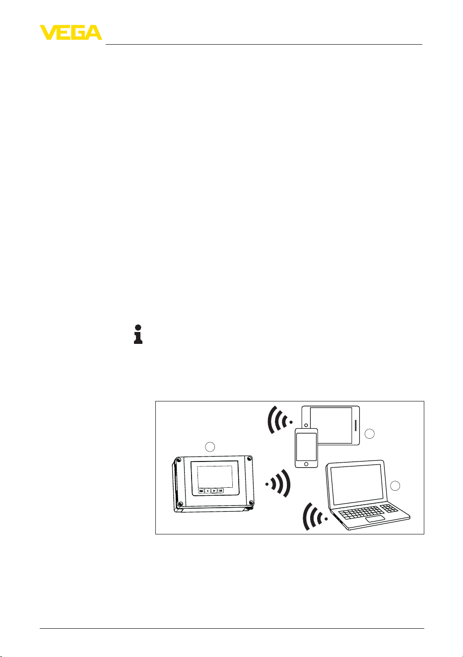
9
3 Product description
VEGAMET Air 841 • LoRaWAN
1104032-EN-260703
Itenableseasyimplementationofpumpcontrols,owmeasurements
on open channels and weirs as well as totalizers. The VEGAMET Air
841 can be used to monitor limit values and switch relays.
The simple connection of radio-based sensors over long distances
enables applications where laying a cable would be too costly or
impossible.
The VEGAMET Air 841 controller evaluates the measurement signals
of wirelessly connected sensors. The requested parameter is shown
on the display and also output to the integrated current output for fur-
ther processing. The measurement signal can thus be transferred to a
remote display or a superordinate control system. Operating relays for
control of pumps or other devices are also integrated.
3.3 Adjustment
On-site adjustment of the device is carried out via the integrated
display and adjustment unit.
The optionally integrated Bluetooth module enables in addition a wire-
less adjustment of VEGAMET Air 841 via standard adjustment tool:
•
Smartphone/tablet (iOS or Android operating system)
•
PC/notebook with Bluetooth LE or Bluetooth USB adapter (Win-
dows operating system)
Information:
Certain setting options are not possible or only possible to a limited
extent with the integrated display and adjustment unit, for example the
settingsforowmeasurementorpumpcontrol.Fortheseapplica-
tions, the use of PACTware/DTM or the VEGA Tools app is recom-
mended. An overview of the available applications and functions as
well as their adjustment options can be found in the appendix.
1
3
2
Fig. 2: Wireless connection to standard adjustment tools with integrated
Bluetooth LE or alternatively Bluetooth USB adapter.
1 VEGAMET Air 841
2 Smartphone/Tablet
3 PC/Notebook
Functional principle
Local adjustment
Wireless adjustment

10
3 Product description
VEGAMET Air 841 • LoRaWAN
1104032-EN-260703
3.4 Packaging, transport and storage
Your instrument was protected by packaging during transport. Its
capacity to handle normal loads during transport is assured by a test
based on ISO 4180.
The packaging consists of environment-friendly, recyclable card-
board. For special versions, PE foam or PE foil is also used. Dispose
of the packaging material via specialised recycling companies.
Transport must be carried out in due consideration of the notes on the
transport packaging. Nonobservance of these instructions can cause
damage to the device.
The delivery must be checked for completeness and possible transit
damage immediately at receipt. Ascertained transit damage or con-
cealed defects must be appropriately dealt with.
Up to the time of installation, the packages must be left closed and
stored according to the orientation and storage markings on the
outside.
Unless otherwise indicated, the packages must be stored only under
the following conditions:
•
Not in the open
•
Dry and dust free
•
Not exposed to corrosive media
•
Protected against solar radiation
•
Avoiding mechanical shock and vibration
•
Storage and transport temperature see chapter "Technical data -
Ambient conditions"
•
Relative moisture 20 … 85 %
3.5 Accessories
The sun protection protects the device from direct sunlight and thus
prevents overheating of the electronics. It also improves the readabil-
ity of the display when exposed to sunlight. The sun protection can be
used for wall and pipe mounting.
The pipe mounting set is used for optimal and safe mounting of the
devices in horizontal and vertical mounting on pipes.
The remote antenna is designed to improve LoRaWAN reception
quality. It is available for wall mounting. The cable length is 3 m.
Packaging
Transport
Transport inspection
Storage
Storage and transport
temperature
Sun shade
Pipe mounting set
Remote antenna

11
4 Mounting
VEGAMET Air 841 • LoRaWAN
1104032-EN-260703
4 Mounting
4.1 General instructions
TheeldhousingoftheVEGAMETAir841isequallysuitablefor
outdoor or indoor installation due to its degree of protection IP66/IP67
and Type 4X. The standard version is designed for wall mounting. A
mounting adapter for pipe mounting is available as an option.
Install the device so that the antenna can freely radiate. If LoRaWAN
reception is poor at the mounting location – for example, if the device
is installed in a metal switching cabinet – a remote antenna can be
used (optional accessory). The cable length is 3 m.
Note:
If third-party antennas are used, the device’s radio licence of the
VEGAMET Air 841 expires.
The instrument is suitable for standard and extended ambient condi-
tions acc. to DIN/EN/BS EN/IEC/ANSI/ISA/UL/CSA 61010-1. It can be
used indoors as well as outdoors.
Avoid direct sunlight or use the optionally available sun shade.
Makesurethattheenvironmentalandambientconditionsspeciedin
chapter "Technical data" are maintained.
Protect your instrument against moisture ingress through the following
measures:
•
Use the recommended connection cable (see chapter "Connect-
ing to power supply")
•
Tighten the cable gland
•
Mount the instrument in such a way that the cable glands point
downward
•
Loop the connection cable downward in front of the cable gland
This applies mainly to outdoor installations, in areas where high
humidity is expected (e.g. through cleaning processes) and on cooled
or heated vessels.
The visible area of the front panel must be protected from knocks,
otherwise water can penetrate through breaking of the front foil. In this
case, protection against accidental contact can no longer be ensured.
Caution:
Make sure that during installation or maintenance no moisture or dirt
can get inside the instrument.
To maintain the housing protection, make sure that the housing lid is
closed during operation and locked, if necessary.
The pressure compensation for the housing is realized via a breather
element.
Mounting options
Mounting location/An-
tenna
Ambient conditions
Protection against mois-
ture
Pressure compensation
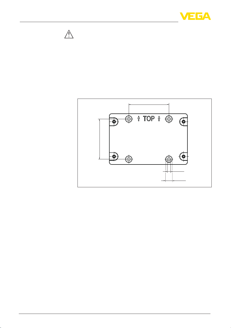
12
4 Mounting
VEGAMET Air 841 • LoRaWAN
1104032-EN-260703
Note:
Make sure that the pressure equalization element is always free of
buildup during operation. A high-pressure cleaner may not be used
for cleaning.
4.2 Mounting instructions
Fix the mounting plate to the wall using the screws and dowels sup-
pliedasshowninthegurebelow.Makesurethatthearrowsonthe
mounting plate point upwards.
Loosen the four screws in the housing cover and open it to the left.
Fasten the device to the mounting plate using the screws (M5) sup-
plied.
82 mm
(3.23")
ø13 mm
(0.51")
ø7 mm
(0.28")
82 mm
(3.23")
Fig. 3: Mounting plate for wall mounting VEGAMET Air 841
The optionally available mounting accessories are required for tube
mounting. The kit consists of two pairs of mounting brackets and four
mounting screws M6 x 100.
The mounting brackets are screwed to the mounting plate and the
tube as shown in the following illustration.
Loosen the four screws in the housing cover and open it to the left.
Fasten the device to the mounting plate using the screws (M5) sup-
plied.
Wall mounting
Tube mounting
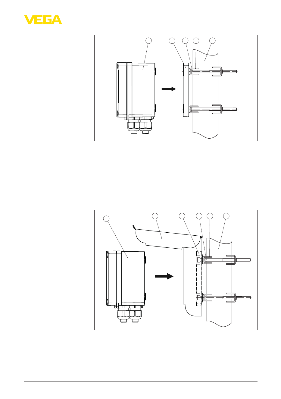
13
4 Mounting
VEGAMET Air 841 • LoRaWAN
1104032-EN-260703
4321
5
Fig. 4: Tube mounting
1 VEGAMET Air 841
2 Mounting plate
3 4 screws M6 x 100
4 Mounting brackets
5 Pipe for diameter 29 … 60 mm (1.14" to 2.36")
The optional sun protection can be used to protect against direct
sunlight. The sunshade is simply mounted behind the mounting plate,
this is possible for both wall and pipe mounting.
542 3
1
6
Fig. 5: Mounting sun protection with pipe mounting
1 VEGAMET Air 841
2 Sun shade
3 Mounting plate
4 4 screws M6 x 100
5 Mounting brackets
6 Pipe for diameter 29 … 60 mm (1.14" to 2.36")
Mounting sun shade
14
5 Connecting to power supply
VEGAMET Air 841 • LoRaWAN
1104032-EN-260703
5 Connecting to power supply
5.1 Preparing the connection
Always keep in mind the following safety instructions:
•
The electrical connection must only be carried out by trained,
qualiedpersonnelauthorisedbytheplantoperator.
•
If overvoltage surges are expected, overvoltage arresters should
be installed.
Warning:
Only connect or disconnect in de-energized state.
Note:
Install a disconnecting device for the instrument which is easy to
access. The separation facility must be designed and rated for the
power consumption of the instrument (IEC/EN 61010).
Thedataforpowersupplyarespeciedinchapter"Technical data".
The instrument belongs to protection class I, hence connection of an
earth conductor is required.
Use cables with a round cross-section. The cable diameter must
matchthecableglandusedtoensurethesealeectivenessofthe
cable gland (IP rating). The permissible cable diameters and torque
arespeciedinthetechnicaldata.Ifthecableglandssuppliedarenot
used,orifthecablediameterisoutsidethespeciedrange,theIP67
protection rating cannot be guaranteed.
The voltage supply is connected with standard cable according to the
national installation standards.
Note:
If the temperatures are too high, the cable insulation can be dam-
aged. Hence keep apart from the ambient temperature also the self-
heating of the instrument for the temperature resistance of the cable
in the connection compartment in mind.
1)
When used in the USA/Canada, only cables with copper conductors
may be used.
Warning:
Indeliverystatus,allopeningsarettedwithdustprotectioncaps.
These caps are only for protection during transport and are not suit-
able for protection during operation! Instead, all openings must be
closed with cable glands/blind plugs.
Cable glands, NPT adapters or blind plugs that are not included in
the scope of delivery must meet the applicable requirements in order
to ensure the environmental compatibility of the housing. For outdoor
Safety instructions
Voltage supply
Connection cable
Cable glands
1)
Withanambienttemperature≥50°C(122°F)theconnectioncableshould
besuitableforanambienttemperaturewhichisatleast20°C(36°F)higher.
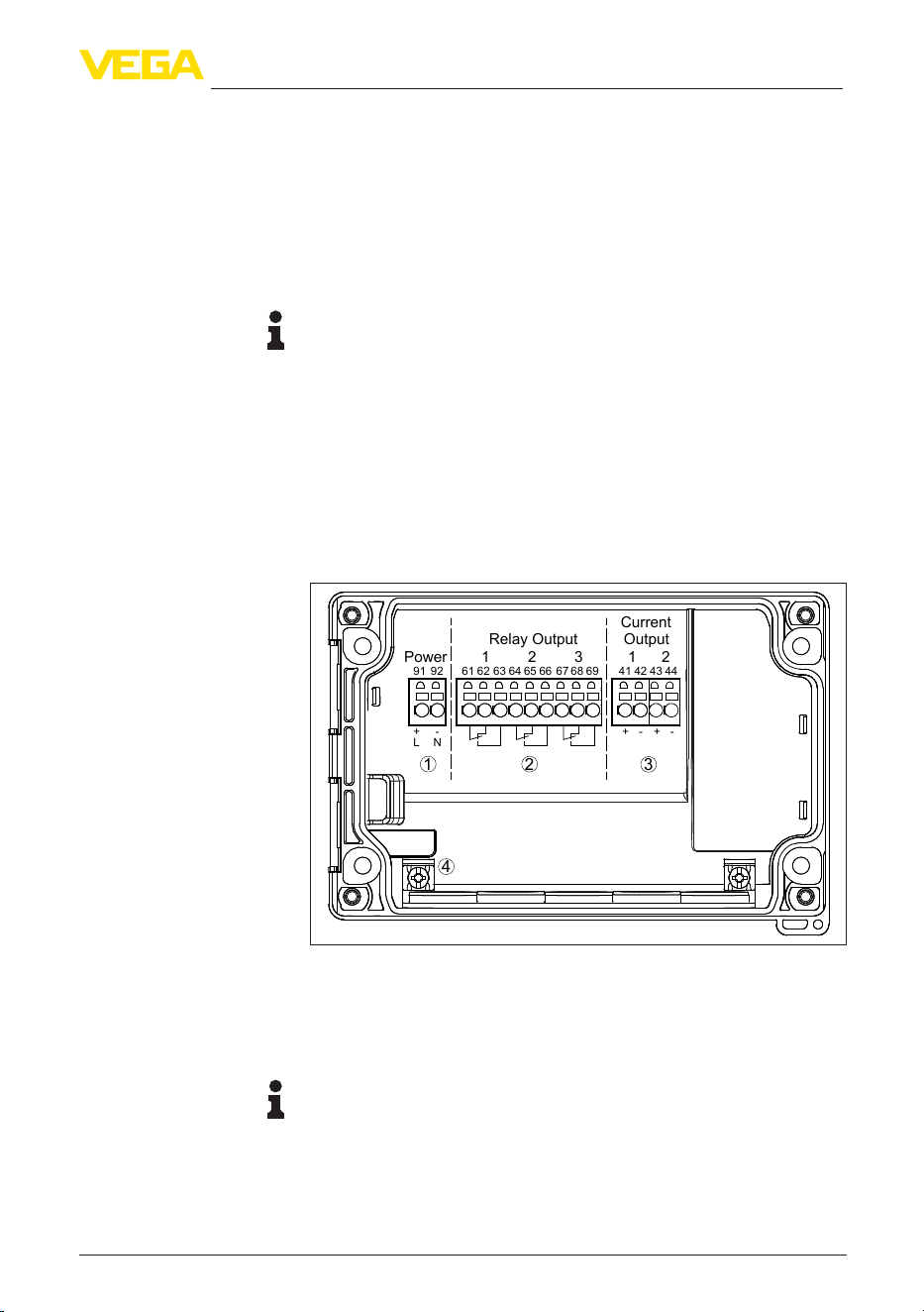
15
5 Connecting to power supply
VEGAMET Air 841 • LoRaWAN
1104032-EN-260703
applications, the weather resistance of the accessories to be used
must be taken into account. The cable glands, NPT adapters and
blind plugs must have a metric thread M20 to be compatible with the
threaded openings of the metal plate in the housing.
5.2 Connecting
The voltage supply and outputs are connected via the spring-loaded
terminals.
Information:
Solidcoresaswellasexiblecoreswithwireendsleevesare
inserteddirectlyintotheterminalopenings.Incaseofexiblecores
without end sleeves, a small screwdriver must be pressed into the
rectangular opening so that the terminal opening is then free. When
the screwdriver is pulled out, the terminals are closed again.
Youcanndfurtherinformationonthemax.wirecross-sectioninthe
technical data.
Connect the device as described in the following wiring plan.
5.3 Wiring plan
1 2
91 92
L N
+ - + - + -
61 62 63 64 65 66 67 68 69
41 42 43 44
Power 321
Relay Output Output
Current
1 2
3
4
Fig. 6: Wiring plan VEGAMET Air 841
1 Voltage supply of the controller
2 Relay outputs 1 … 3
3 Current outputs 1/2
4 Ground terminal for protective conductor
Note:
Mixed operation with hazardous voltages (> 30 V AC, > 60 V DC) and
non-hazardous voltages (< 30 V AC, < 60 V DC) is not permitted for
the relay outputs.
Connection technology
Connecting

16
5 Connecting to power supply
VEGAMET Air 841 • LoRaWAN
1104032-EN-260703
5.4 Switch-on phase
Afterswitchingon,thedevicerstcarriesoutashortself-check.
•
Internal check of the electronics
•
Output signals are set to malfunction, backlight of the display
lights red
The current measured values are then displayed and transmitted to
the outputs. The backlight of the display changes to white.

17
6 Access protection
VEGAMET Air 841 • LoRaWAN
1104032-EN-260703
6 Access protection
6.1 Bluetooth radio interface
Devices with a Bluetooth radio interface are protected against un-
wanted access from outside. This means that only authorized persons
can receive measured and status values and change device settings
via this interface.
Information:
If no Bluetooth connection to the device should be possible, Bluetooth
communication can be deactivated. Access via app or DTM is thus no
longer possible. The Bluetooth function can be deactivated/activated
in the menu item "Extended functions" under "Access protection -
Bluetooth communication".
A Bluetooth access code is required to establish Bluetooth com-
munication via the adjustment tool (smartphone/tablet/notebook).
This code must be entered once when Bluetooth communication is
establishedforthersttimeintheadjustmenttool.Itisthenstoredin
the adjustment tool and does not have to be entered again.
The Bluetooth access code is individual for each device. It is printed
on the device housing and is also supplied with the device in the
information sheet "PINs and Codes". The Bluetooth access code can
also be read out via the display and adjustment unit.
TheBluetoothaccesscodecanbechangedbytheuseraftertherst
connection is established. If the Bluetooth access code is entered
incorrectly, the new entry is only possible after a waiting period has
elapsed. The waiting time increases with each further incorrect entry.
The emergency Bluetooth access code enables Bluetooth communi-
cation to be established in the event that the Bluetooth access code
is no longer known. It can't be changed. The emergency Bluetooth
access code can be found in information sheet "Access protection".
If this document is lost, the emergency Bluetooth access code can
be retrieved from your personal contact person after legitimation.
The storage and transmission of Bluetooth access codes is always
encrypted (SHA 256 algorithm).
6.2 Protection of the parameterization
The settings (parameters) of the device can be protected against un-
wanted changes. The parameter protection is deactivated on delivery,
all settings can be made.
To protect the parameterization, the device can be locked by the user
with the aid of a freely selectable device code. The settings (param-
eters) can then only be read out, but not changed. The device code
is also stored in the adjustment tool. However, unlike the Bluetooth
access code, it must be re-entered for each unlock. When using the
adjustment app or DTM, the stored device code is then suggested to
the user for unlocking.
Bluetooth access code
Emergency Bluetooth
unlock code
Device code

18
6 Access protection
VEGAMET Air 841 • LoRaWAN
1104032-EN-260703
The emergency device code allows unlocking the device in case the
device code is no longer known. It can't be changed. The emergency
device code can also be found on the supplied information sheet "Ac-
cess protection". If this document is lost, the emergency device code
can be retrieved from your personal contact person after legitimation.
The storage and transmission of the device codes is always encrypt-
ed (SHA 256 algorithm).
6.3 Storing the codes in myVEGA
If the user has a "myVEGA" account, then the Bluetooth access code
as well as the device code are additionally stored in his account under
"PINs and Codes".Thisgreatlysimpliestheuseofadditionaladjust-
ment tools, as all Bluetooth access and device codes are automati-
cally synchronized when connected to the "myVEGA" account
Emergency device code
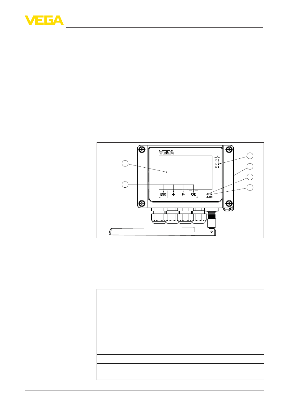
19
7 Set up with the integrated display and adjustment unit
VEGAMET Air 841 • LoRaWAN
1104032-EN-260703
7 Set up with the integrated display and
adjustment unit
7.1 Adjustment system
The integrated display and adjustment unit is used for measured
value display, adjustment and diagnosis of the VEGAMET Air 841.
Display and adjustment are carried out via four keys and a graphic-
capable display with background lighting.
Certain setting options are not possible or only possible to a limited
extent with the integrated display and adjustment unit, for example the
settingsforowmeasurementorpumpcontrol.Fortheseapplica-
tions, the use of PACTware/DTM or the VEGA Tools app is recom-
mended. A tabular overview of the corresponding applications and
functions can be found in the appendix.
1
3
4
2
5
6
Fig. 7: Display and adjustment elements
1 LC display
2 Adjustment keys
3 Status indication relay
4 NFC reader
5 Status indication fault signal
6 Status indication operation
Key Function
[OK] Entry to the menu level
Jump to selected menu item
Edit parameter
Save value
[>] Switching between the individual measured value indications
Navigation in the menu items
Select editing position
[+] Change parameter values
[ESC] Jump to next higher menu
Interrupt input
Function
Display and adjustment
elements
Key functions
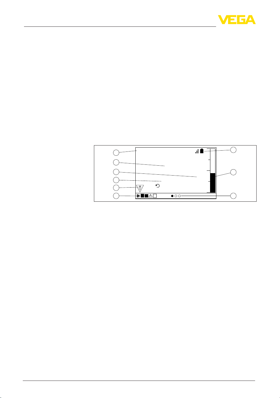
20
7 Set up with the integrated display and adjustment unit
VEGAMET Air 841 • LoRaWAN
1104032-EN-260703
When the [+] and [->] keys are pressed quickly, the edited value,
or the cursor, changes one value or position at a time. If the key is
pressed longer than 1 s, the value or position changes continuously.
Approx. 60 minutes after the last pressing of a key, an automatic reset
tomeasuredvalueindicationistriggered.Anyvaluesnotconrmed
with [OK] will not be saved.
7.2 Measured value and menu item display
The measured value display shows the digital display value, the
measuring loop name (measuring loop TAG) and the unit. In addition,
an analogue bar graph can be displayed. Up to three measured value
indicationswithamaximumthreedierentmeasuredvaluescanbe
congured.Ifpumpcontrolisactivated,anadditionalstatusbarwith
display of the assigned pumps is available.
Measured values are displayed according to the following presenta-
tion:
1
2
3
5
4
6
8
9
7
PULS 78209666
m
Last Value
5 Mins ago
1.8523
1 2
Fig. 8: Example measured value indication (measured value with bargraph)
1 Measurement loop name
2 Measured value
3 Unit
4 Last transmitted measured value
5 Status message acc. to NAMUR NE 107
6 Status bar for pump control
7 Active measured value indication
8 Bargraph measured value
9 Signal strength indicator (LoRa) and battery level (sensor)
The display is equipped with a backlight for better visibility. It serves
simultaneously as a status display which is also visible from a great
distance. The colour of the background lighting changes in the deliv-
ery status according to NAMUR NE 107.
•
White: Error-free operation
•
Red: Failure, error, malfunction
•
Orange: Function check
•
Blue: Maintenance required
•
Yellow:Outsidethespecication
Alternatively, the status display can also show the switching status of
therelaysormeasuredvaluerangesindividuallywithfreelydenable
colours.Uptovemeasuredvalueranges,e.g.,dependingonthe
llinglevel,canbedisplayedindierentcolours.Thebackground
lightingcanalsobeconguredtoashinanycolourasanadditional
signalling option.
Time functions
Measured value indica-
tion
Status display/backlight
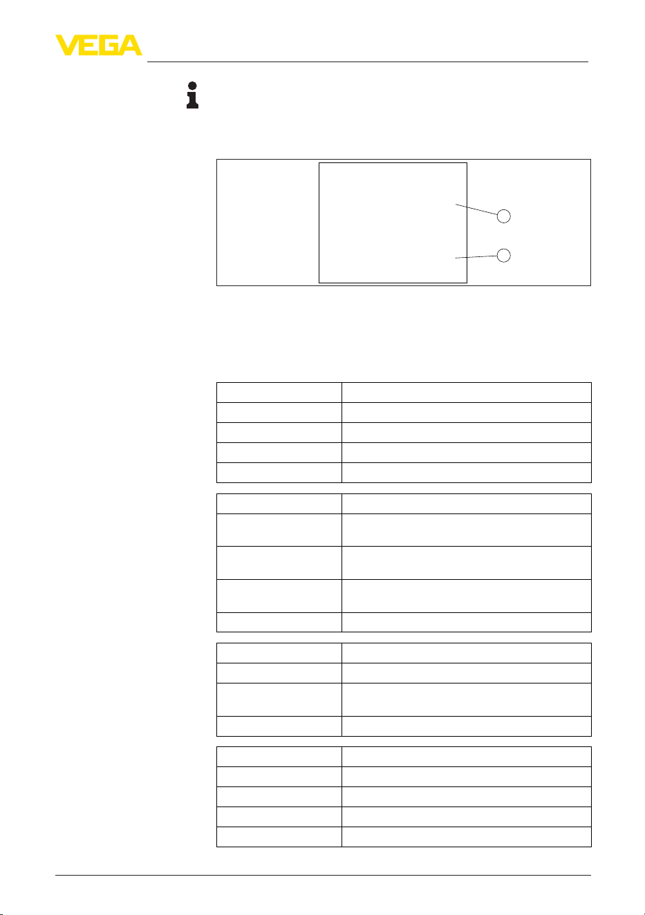
21
7 Set up with the integrated display and adjustment unit
VEGAMET Air 841 • LoRaWAN
1104032-EN-260703
Information:
ThisindividualcoloursignallingisconguredwithPACTware/DTMor
the VEGA Tools App.
The menu items are displayed according to the following presentation:
1
2
Max.Adjustment
Sensor value at 100% :
Current Sensor value:
1.8523
m
14,83
m
Fig. 9: Menu item display (example)
1 Sensor measured value at 100 %
2 Current sensor measured value
7.3 Menu overview
Description Basic settings
Linearisation Linearization settings
Adjustment Adjustment settings
Scaling Scaling settings
Outputs Relay/current output settings
Description Basic settings
Number of measured
value indications
Number of displayed measured value indications
Measured value indi-
cation
Settings for the measured value displays, automatic
change of the measured value display
Options Display options e.g. brightness, contrast, illumina-
tion
Menu language Language settings
Description Basic settings
Fail safe relay Activate/deactivate fail safe relay
Access protection Access protection for Bluetooth and protection of
the parameter adjustment
Reset Reset of the device
Description Basic settings
Status Status indication, e.g. device, sensor, relay
Simulation Simulation function
Device-TAG Display device name
Device information Device information, e.g. serial number
Menu item display
Measurement loop
Indication
Extended functions
Diagnostics

22
7 Set up with the integrated display and adjustment unit
VEGAMET Air 841 • LoRaWAN
1104032-EN-260703
7.4 Setup steps
TherststepistopairthesensorwithVEGAMETAir841.WithVEGA
sensors his is done very easily and automatically via the built-in NFC
reader.
Through parameter adjustment, the instrument is adapted to the indi-
vidual application conditions. A measurement loop calibration is the
most important step and should always be carried out. A scaling of
the measured value to the desired physical variable and unit, possibly
including a linearization curve, is often useful. The adaptation of the
relay switching points is a further standard adjustment option.
Information:
When using PACTware and the respective DTM or the
VEGA Tools app, additional settings can be carried out which are
not possible or only partly possible with the integrated display and
adjustment unit. Communication takes place via the built-in Bluetooth
interface.
Thedeviceisconguredexworksforuniversalapplications.The
followingapplicationscanbechangedoverandconguredviathe
VEGA Tools app or the DTM:
•
Universal
•
Level - storage tank
•
Wells
•
Pumping station
•
Sewage screw lifting station
•
Flowmeasurementume/weir
Information:
An overview of the available applications and functions can be found
in the appendix
This function allows the VEGA LoRa sensors to be paired with the
VEGAMET Air 841 quickly and easily. When the function is launched,
the built-in NFC reader is activated for 30 seconds. If the LoRa sensor
is held against the right-hand side of the VEGAMET Air 841 during
this time, the two devices will pair automatically. If a sensor is already
connected, it can be replaced by the new one.
The menu is divided into four areas with the following functions:
•
Measuring point: Includes settings for adjustment, linearization,
scaling, relay outputs, …
•
Display: Contains settings for display of measured values
•
Extended functions: Includes settings for fail safe relay, access
protection, reset, …
•
Diagnosis Includes information on device type/status, …
7.4.1 Measurement loop
A linearisation is necessary for all vessels in which the vessel volume
does not increase linearly with the level, for example a horizontal
Pair the sensor
Parameter adjustment
Applications
Add/exchange a sensor
Menu
Linearisation

23
7 Set up with the integrated display and adjustment unit
VEGAMET Air 841 • LoRaWAN
1104032-EN-260703
cylindrical or spherical tank. Corresponding linearisation curves are
preprogrammed for these vessels. They represent the correlation
between the level percentage and vessel volume. By activating the
appropriate curve, the volume percentage of the vessel is displayed
correctly. If the volume should not be displayed in percent but e.g. in l
or kg, a scaling can be also set.
Whensettingupaowmeasurement,alinearizationcurvesuitable
for the structural conditions must be selected. Corresponding curves
suchasventuri,triangularoverow,…areavailablehere.Inaddition,
individual, user-programmable linearisation curves can be stored via
DTM.
Through the adjustment the input value of the connected sensor is
converted into a percentage value. This conversion step allows any
input value range to be depicted in a relative range (0 % up to 100 %).
The percentage values can be used for presentation on the display,
for direct use in an output or for further conversion via linearization or
scaling.
When using the display and adjustment unit, the adjustment unit
is always the physical measured value of the sensor. When using
PACTware/DTM or the VEGA Tools app, further units can be selected.
If these have been activated, they are also shown in the display.
Min. adjustment (empty vessel)
If you want to use the currently measured level as a 0 %value, select
the menu item "Accept" (live adjustment or adjustment with medium).
If the adjustment is to be carried out independently of the measured
level, select the option "Edit". Now enter the appropriate measured
value for the empty vessel (0 %) (dry adjustment or adjustment with-
out medium).
Max. adjustment (full vessel)
If you want to use the currently measured level as a 100 %value,
select the menu item "Accept" (live adjustment or adjustment with
medium). If the adjustment is to be carried out independently of the
measured level, select the option "Edit". Now enter the appropriate
measured value for the full vessel (100 %) (dry adjustment or adjust-
ment without medium).
Scaling means converting the measured value into a certain param-
eter and unit. The linearized percentage value is the source signal
which is used as basis for the scaling. The indication can then show
the volume in litres e.g., instead of the percentage value. Indication
values from max. -9999999 to +9999999 are possible.
A total of three relays is available. Relays 1 … 2 are freely available
and not yet assigned to a function. To be able to use these relays, they
mustrstbeactivated.Relay3isconguredinthefactoryasafail
saferelay,butcanalsobeconguredasadditionaloperatingrelay.
After activating a relay output, the desired mode of operation must
rstbeselected("Overll protection/Dry run protection").
Adjustment
Scaling
Outputs - Relay outputs

24
7 Set up with the integrated display and adjustment unit
VEGAMET Air 841 • LoRaWAN
1104032-EN-260703
•
Overllprotection:Relayisswitchedowhenthemax.levelis
exceeded (safe currentless state), relay is switched on again when
thelevelfallsbelowthemin.level(switch-onpoint<switch-o
point)
•
Dry run protection:Relayisswitchedowhenthelevelfalls
below the min. level (safe currentless state), relay is switched on
again when the max. level is exceeded (switch-on point > switch-
opoint)
Additional modes such as "Pump control", "Switching window",
"Flow" and "Tendency" can be only set via PACTware/DTM or the
VEGA Tools app.
In the menu item "Reference value"itisdenedwhichmeasured
value serves as input signal for the relay (percentage/lin.-percent/
scaled).
EnterthevaluesforswitchingtherelayonandounderEnterthe
valuesforswitchingtherelayonandounder"Switching point".
The menu item "Behaviour in case of malfunction"deneshowthe
relay behaves if the assigned measuring point is disturbed. Here
it can be selected whether the switching state of the relay remains
unchangedorwhethertherelayisswitchedointheeventofa
malfunction.
The current output is used to transfer the measured value to a super-
ordinate system, e.g. a PLC, a process control system or a measured
value indication. This is an active output, i.e. the current is provided
actively. The processing must hence have a passive current input. If
thecurrentoutputisnotused,itcanbedeactivatedintherstmenu
item.
The characteristics of the current output can be set to 0 … 20 mA,
4 … 20 mA or inverted. The reaction in case of failure can also be
adapted to the requirements. The reference value you refer to can
also be selected.
7.4.2 Indication
Theindicationcandisplayuptothreedierent,user-congurable
measuredvaluessimultaneously.Inaddition,uptothreedierent
measuredvalueindicationscanbecongured,whichcanbeselected
using the arrow keys. Alternatively, the display of the measured value
indications can also be changed automatically at intervals of approx.
3 seconds.
In the menu item "Display - Number of measured value indications"
youcancongurehowmanymeasuredvalueindicationsaretobe
displayed.
Thecontentofthemeasuredvalueindicationisconguredinthe
menu item "Display - Measured value indication".Upto3dier-
ent measured values can be displayed in one indication. For each
measuredvalueitisalsopossibletocongurewhichdisplayvalue
(percent, scaled, sensor value, …) is displayed. In addition, the dis-
playformat(numberofdecimalpositions)canalsobecongured.In
Outputs - Current output
Number of measured
value indications
Measured value indica-
tion 1 … 3

25
7 Set up with the integrated display and adjustment unit
VEGAMET Air 841 • LoRaWAN
1104032-EN-260703
addition, a bar graph can be displayed parallel to the measured value
(only available when displaying a single measured value).
In the menu item "Display - Options - Brightness" the brightness of the
backlight can be adjusted.
In the menu item "Display - Options - Contrast" the contrast of the
display can be adjusted.
In the menu item "Display - Options - Lighting" the lighting can be set
permanently to "Permanently ON" or "Automatically OFF" (after two
minutes). With the setting "Automatically OFF" the lighting is switched
on for two minutes as soon as any button is pressed.
In the menu item "Display - Menu language", the requested language
can be adjusted. The following languages are available:
•
German
•
English
•
French
•
Spanish
•
Portuguese
•
Italian
•
Dutch
•
Russian
•
Chinese
•
Japanese
•
Turkish
7.4.3 Extended functions
Relay3canoptionallybeconguredasadditionaloperatingrelayor
as a fail safe relay. In this menu item, the fail safe relay can be activat-
edordeactivated.Ifrelay3istobeconguredasanoperatingrelay,it
must still be activated as an operating relay after deactivation as a fail
safe relay. This is done in menu item"Measuring point - Relay 3"
Bluetooth communication can be activated/deactivated in this menu
item. If Bluetooth communication is deactivated, a connection via app
or DTM is no longer possible.
Youcanndfurtherdetailsinchapter"Access protection".
Bluetooth communication is encrypted to prevent unauthorized
access. The Bluetooth access code required for communication is
displayed here and can be changed as required.
Note:
The individual, default Bluetooth access code of the device can be
found on the device housing and on the supplied information sheet
"PINs and Codes". If this has been changed by the user and is no
longer known, access is only possible via the emergency Bluetooth
accesscode.YoucanndtheemergencyBluetoothaccesscodeon
the supplied information sheet "Access protection"
Options - Brightness
Options - Contrast
Options - Lighting
Menu language
Fail safe relay
Access protection -
Bluetooth communication
Access protection -
Bluetooth access code
26
7 Set up with the integrated display and adjustment unit
VEGAMET Air 841 • LoRaWAN
1104032-EN-260703
Youcanndfurtherdetailsinchapter"Access protection".
The device parameters can be protected against unwanted or unin-
tended changes by entering a device code.
With activated protection of the parameter adjustment, the individual
menu items can be selected and displayed, however the parameters
cannolongerbemodied.
Releasing the device adjustment is also possible in any menu item by
entering the device code.
Note:
The default device code is "000000". If this has been changed by the
user and is no longer known, access is only possible via the emer-
gencydevicecode.Youwillndtheemergencydevicecodeonthe
supplied information sheet "Access protection"
Caution:
With protected parameter adjustment, adjustment via the
VEGA Tools app as well as PACTware/DTM and other systems is also
blocked.
Youcanndfurtherdetailsinchapter"Access protection".
With a reset to basic setting, all settings except the display language
and the Bluetooth access code are reset to factory settings. If desired,
the device can also be restarted.
7.4.4 Diagnostics
When the instrument displays a fault signal, further information about
the malfunction can be called up via the menu item "Diagnosis -
Status". Furthermore, the sensor status with temperature and location
can be displayed. The status of the relay, its switched-on period and
the number of switch-on events can also be displayed. The counters
can also be reset.
The simulation of a measured value is used to check the outputs and
connected components. It can be applied to the sensor value, the per-
centage value, the lin. percentage value as well as the scaled value.
Note:
Please note that downstream plant components (valves, pumps,
motors,controls)areinuencedbythesimulation,whichcanlead
to unintentional plant operating states. The simulated value is output
until you deactivate the simulation mode again. The simulation is
automatically terminated after approx. 60 minutes.
You can assign an unambiguous name to VEGAMET Air 841 to the
Device-TAG via DTM/VEGA Tools app. This function is recommended
when several instruments are implemented and a good documenta-
tion of larger systems is required.
The menu item "Device information" provides the device name and
serial number as well as the hardware and software version.
Access protection - Pro-
tection of the parameter
adjustment
Reset
Status
Simulation
Device-TAG
Device information
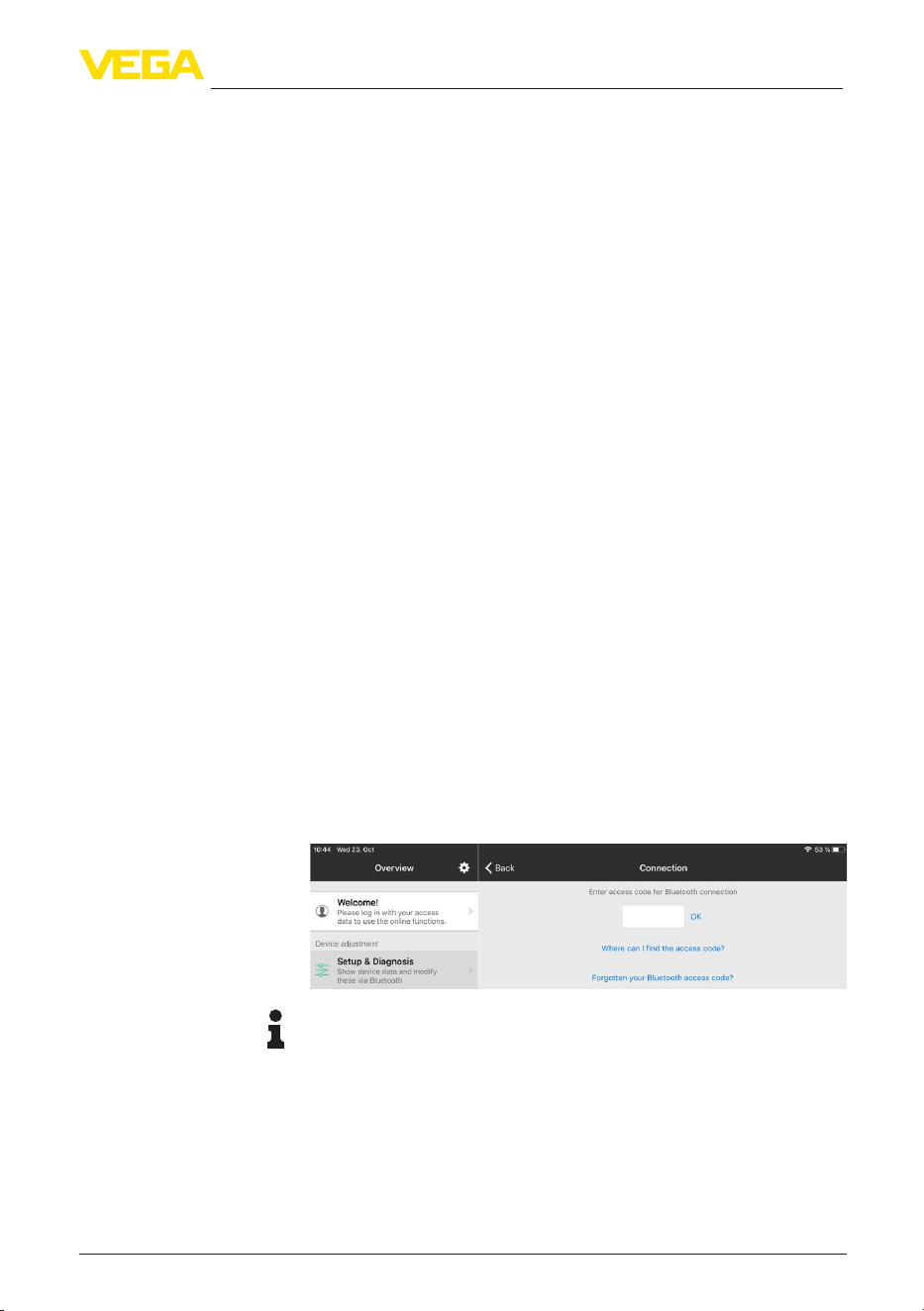
27
8 Setup with smartphone/tablet (Bluetooth)
VEGAMET Air 841 • LoRaWAN
1104032-EN-260703
8 Setup with smartphone/tablet (Bluetooth)
8.1 Preparations
Make sure that your smartphone/tablet meets the following system
requirements:
•
Operating system: iOS 13 or newer
•
Operating system: Android 8.0 or newer
•
Bluetooth 4.0 LE or newer
Download the VEGA Tools app from the "Apple App Store", "Goog-
le Play Store" or "Baidu Store" to your smartphone or tablet.
8.2 Connecting
Start the VEGA Tools app and select the function "Setup". The smart-
phone/tablet searches automatically for Bluetooth-capable instru-
ments in the area.
The devices found are listed and the search is automatically contin-
ued.
Select the requested instrument in the device list.
As soon as the Bluetooth connection to a device is established, the
LEDdisplayofthedeviceinquestionashesblue4times.
The message "Connecting …" is displayed.
Whenestablishingtheconnectionforthersttime,theoperatingtool
andthecontrollermustauthenticateeachother.Aftertherstcorrect
authentication, each subsequent connection is made without a new
authentication query.
For authentication, enter the 6-digit Bluetooth access code in the
nextmenuwindow.Youcanndthecodeontheoutsideofthedevice
housing and on the information sheet "Pins and Codes" in the device
packaging.
Note:
If an incorrect code is entered, the code can only be entered again
after a delay time. This time gets longer after each incorrect entry.
The message "Waiting for authentication" is displayed on the smart-
phone/tablet.
After connection, the adjustment menu is displayed on the respective
adjustment tool.
System requirements
Connecting
Authenticate
Enter Bluetooth access
code
Connected
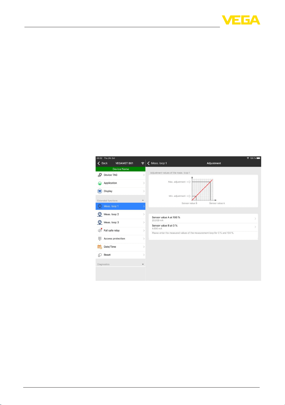
28
8 Setup with smartphone/tablet (Bluetooth)
VEGAMET Air 841 • LoRaWAN
1104032-EN-260703
If the Bluetooth connection is interrupted, e.g. due to a too large
distance between the two devices, this is displayed on the adjustment
tool. The message disappears when the connection is restored.
Parameter adjustment of the device is only possible if the parameter
protection is deactivated. When delivered, parameter protection is
deactivated by default and can be activated at any time.
It is recommended to enter a personal 6-digit device code. To do this,
go to menu "Extended functions", "Access protection", menu item
"Protection of the parameter adjustment".
8.3 Parameter adjustment
The adjustment menu is divided into two halves:
Ontheleftyouwillndthenavigationareawiththemenus"Setup",
"Extended functions" as well as "Diagnosis".
The selected menu item, recognisable by the colour change, is dis-
played in the right half.
Fig. 10: Example of an app view - Setup adjustment
Entertherequestedparametersandconrmviathekeyboardorthe
editingeld.Thesettingsarethenactiveinthedevice.
Close the app to terminate connection.
Change device code
Enter parameters
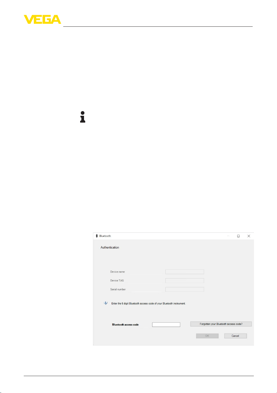
29
9 Setup with PC/notebook (Bluetooth)
VEGAMET Air 841 • LoRaWAN
1104032-EN-260703
9 Setup with PC/notebook (Bluetooth)
9.1 Preparations
Make sure that your PC/notebook meets the following system require-
ments:
•
Operating system Windows 10 or newer
•
DTM Collection 10/2020 or newer
•
Bluetooth 4.0 LE or newer
Activate the Bluetooth connection via the project assistant.
Note:
Older systems do not always have an integrated Bluetooth LE. In
these cases, a Bluetooth USB adapter is required. Activate the
Bluetooth USB adapter using the Project Wizard.
After activating the integrated Bluetooth or the Bluetooth USB adapt-
er, devices with Bluetooth are found and created in the project tree.
9.2 Connecting
Select the requested device for the online parameter adjustment in
the project tree.
Whenestablishingtheconnectionforthersttime,theoperatingtool
andthecontrollermustauthenticateeachother.Aftertherstcorrect
authentication, each subsequent connection is made without a new
authentication query.
For authentication, enter in the next menu window the 6-digit
Bluetooth access code:
Youcanndthecodeontheinformationsheet"PINs and Codes" in
the device packaging:
System requirements
Activate Bluetooth con-
nection
Connecting
Authenticate
Enter Bluetooth access
code
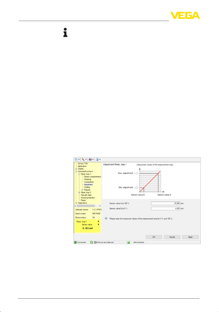
30
9 Setup with PC/notebook (Bluetooth)
VEGAMET Air 841 • LoRaWAN
1104032-EN-260703
Note:
If an incorrect code is entered, the code can only be entered again
after a delay time. This time gets longer after each incorrect entry.
The message "Waiting for authentication" is displayed on the PC.
After connection, the DTM appears.
If the connection is interrupted, e.g. due to a too large distance
between controller and PC, this is displayed on the PC. The message
disappears when the connection is restored.
Parameter adjustment of the device is only possible if the parameter
protection is deactivated. When delivered, parameter protection is
deactivated by default and can be activated at any time.
It is recommended to enter a personal 6-digit device code. To do this,
go to menu "Extended functions", "Access protection", menu item
"Protection of the parameter adjustment".
9.3 Parameter adjustment
For parameter adjustment of the instrument via a Windows PC, the
congurationsoftwarePACTwareandasuitableinstrumentdriver
(DTM) according to FDT standard are required. The latest PACTware
version as well as all available DTMs are compiled in a DTM Collec-
tion. The DTMs can also be integrated into other frame applications
according to FDT standard.
Fig. 11: Example of a DTM view - Adjustment
Connected
Change device code
Prerequisites

31
10 Applications and functions
VEGAMET Air 841 • LoRaWAN
1104032-EN-260703
10 Applications and functions
The controller contains already preset applications and functions,
which can be easily adjusted by means of an application assistant via
PACTware/DTM or the VEGA Tools app. The following applications/
functions are described here as examples.
•
Levelmeasurementinstoragetankswithoverllprotection/dryrun
protection
•
Pump station with pump control function
•
Screen control
•
Flowmeasurementume/weir
10.1 Application example
ToDo

32
11 Diagnostics and servicing
VEGAMET Air 841 • LoRaWAN
1104032-EN-260703
11 Diagnostics and servicing
11.1 Maintenance
If the device is used properly, no special maintenance is required in
normal operation.
The cleaning helps that the type label and markings on the instrument
are visible.
Take note of the following:
•
Use only cleaning agents that do not damage the housing, type
plate or seals, e.g. a cloth dampened with water
•
Use only cleaning methods corresponding to the housing protec-
tion rating
11.2 Rectify faults
The operator of the system is responsible for taking suitable meas-
ures to rectify faults.
Thedeviceoersmaximumreliability.Nevertheless,faultscanoccur
during operation. These may be caused by the following, e.g.:
•
Measured value from sensor not correct
•
Voltage supply
•
Interference in the cables
Therstmeasuresare:
•
Evaluation of fault messages
•
Checking the input/output signal
A smartphone/tablet with the VEGA Tools app or a PC/notebook with
thesoftwarePACTwareandthesuitableDTMoeryoufurthercom-
prehensive diagnostic possibilities. In many cases, the causes can be
determined in this way and the malfunctions eliminated.
Depending on the reason for the fault and the measures taken, the
steps described in chapter "Setup" must be carried out again or must
be checked for plausibility and completeness.
Should these measures not be successful, please call in urgent cases
the VEGA service hotline under the phone no. +49 1805 858550.
The hotline is also available outside normal working hours, seven
days a week around the clock.
Sinceweoerthisserviceworldwide,thesupportisprovidedin
English. The service itself is free of charge, the only costs involved are
the normal call charges.
11.3 Diagnosis, fault messages
The controller and the connected sensors are permanently monitored
during operation and the values entered during parameter adjust-
ment are checked for plausibility. If irregularities occur or in case of
Maintenance
Cleaning
Reaction when malfunc-
tion occurs
Causes of malfunction
Faultrectication
Reaction after fault recti-
cation
24 hour service hotline
Fault signal
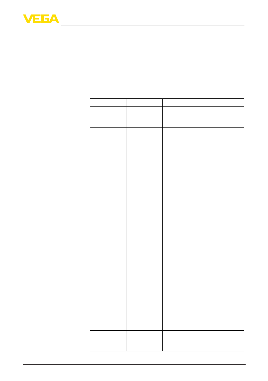
33
11 Diagnostics and servicing
VEGAMET Air 841 • LoRaWAN
1104032-EN-260703
incorrect parameter adjustment, a fault signal is triggered. In case of
an instrument defect and a failed data transfer, a fault signal is also
triggered.
The fault indication lights up in case of failure and the current output
aswellastherelaysreactaccordingtotheconguredfaultmode.If
thefailsaferelaywascongured,itwilldeenergize.Inaddition,one
of the following error messages is outputted on the display and the
background lighting changes to colour acc. to NAMUR NE 107 (e.g.
red in case of a fault, orange in case of a function check).
Error code Cause Rectication
F003
Hardware: CRC
error
CRC error (error
with self-check)
Switchtheinstrumento/on
Carry out a reset
Send instrument for repair
F008
Sensor not ac-
cessible
No sensor da-
ta has been
received for
some time
Reduce distance to the sensor
Use external antenna
Exchange battery in the sensor
F012
Sensor input:
Hardware error
Hardware error,
sensor input
Switchtheinstrumentoandon
Send instrument for repair
F013
Sensor input:
Sensor error
The input of the
measuring point
returns an error
The connected
sensor returns
an error
Switchdevice/sensoroanon
Send device/sensor for repair
F034
EEPROM: CRC
error
EEPROM: CRC
error
Switchtheinstrumentoandon
Carry out a reset
Send instrument for repair
F035
ROM: CRC error
ROM: CRC error Switchtheinstrumentoandon
Carry out a reset
Send instrument for repair
F036
No operable
software
No executable
program
Software update
failed
Carry out another software update
Send instrument for repair
F037
RAM
RAM defective Switchtheinstrumentoandon
Carry out a reset
Send instrument for repair
F039
No join within 24
hours
No join request
was received
from the sensor
24 hours after
the NFC/DTM
pairing
Place the sensor next to VEGAMET Air
841 and perform a manual join on the
sensor
F040
General hard-
ware error
Hardware error Switchtheinstrumentoandon
Carry out a reset
Send instrument for repair
Failure
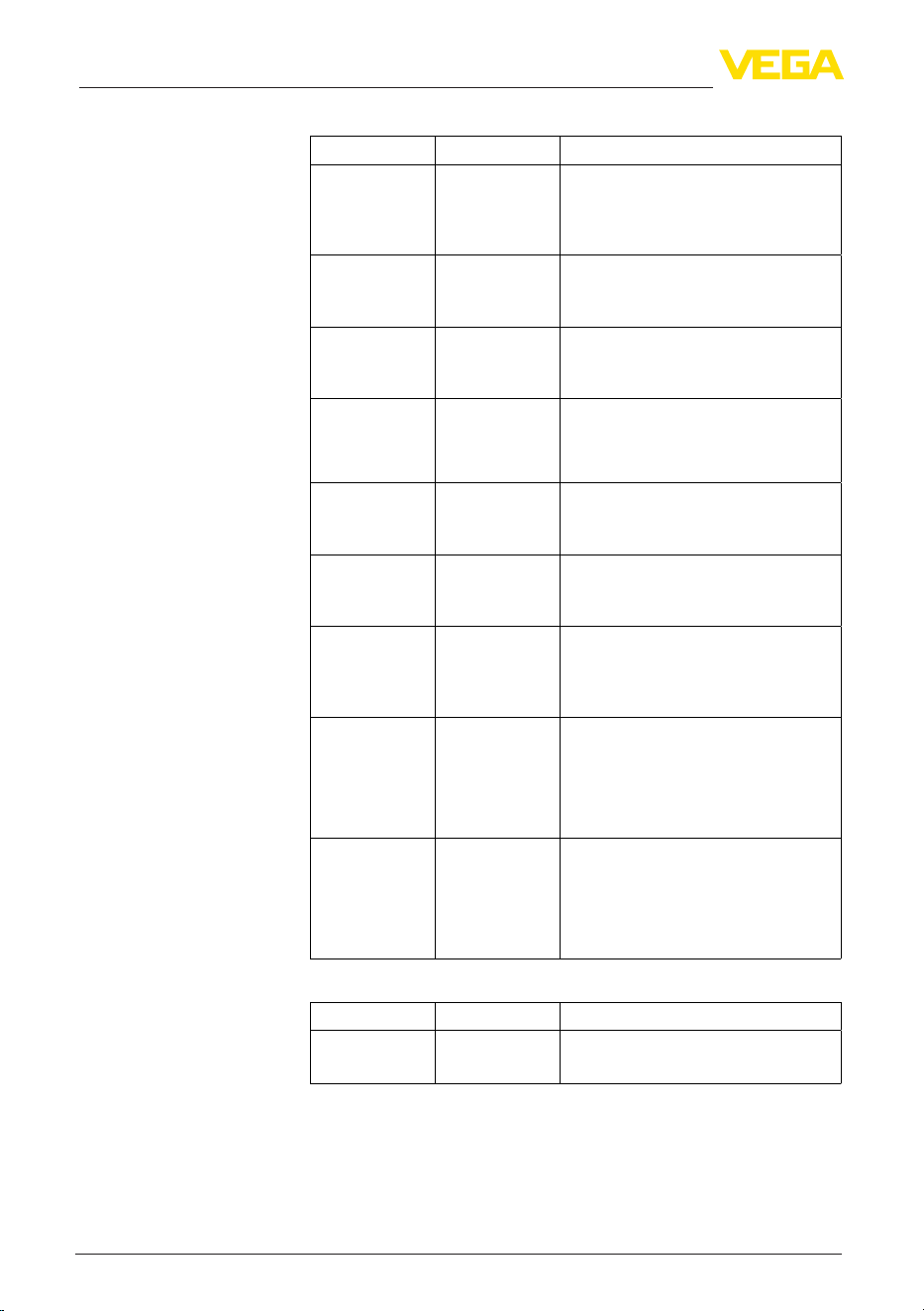
34
11 Diagnostics and servicing
VEGAMET Air 841 • LoRaWAN
1104032-EN-260703
Error code Cause Rectication
S016
Adjustment:
Min./Max. ex-
changed
The min./max.
adjustment
points were ex-
changed.
Carry out the adjustment again, correct
the min. and max. values.
S017
Adjustment:
Span too small
Adjustment span
too small
Carry out a fresh adjustment and in-
crease the distance between min./max.
adjustment
S021
Scaling: Span
too small
Scaling span too
small
Carry out a fresh scaling, increase the
distance between min./max. scaling.
S022
Scaling: Scaling
value too large
Value for one
of the two scal-
ing points is too
large
Carry out the scaling again, correct the
min. and max. values.
S062
Pulse priority too
small
Pulse priority too
small
Increase under "Output" the entry
"Pulse output all" so that max. one pulse
per second is output.
S110
Relay: Span too
small
Relay switching
points too close
together
Increasethedierencebetweenthetwo
relay switching points
S111
Relay: Switching
points inter-
changed
Relay switching
points inter-
changed
Change relay switching points for "On/
O"
S115
Pump control:
Faulty interfer-
ence behaviour
Several relays
are assignef to
the pump control
which are not set
to the same fail-
ure mode
All relays which are assigned to the
pump control must be set to the same
failure mode
S116
Pump control:
Operating mode
faulty
Several relays
that are not con-
guredwiththe
same mode are
assigned to the
pump control
All relays which are assigned to the
pump control must be set to the same
mode
Error code Cause Rectication
C029
Simulation
Simulation active Finish simulation
11.4 Software update
An update of the device software is possible via the Bluetooth inter-
face.
The following components are required:
Outofspecication
Function check

35
11 Diagnostics and servicing
VEGAMET Air 841 • LoRaWAN
1104032-EN-260703
•
Instrument
•
Voltage supply
•
PC/Notebook with PACTware/DTM
•
Currentinstrumentsoftwareasle
Youcanndthecurrentinstrumentsoftwareaswellasdetailed
information on the procedure in the download area of our homepage:
www.vega.com.
Caution:
Instruments with approvals can be bound to certain software versions.
Thereforemakesurethattheapprovalisstilleectiveafterasoftware
update is carried out.
Youcannddetailedinformationinthedownloadareaat
www.vega.com.
11.5 How to proceed if a repair is necessary
Onourhomepageyouwillnddetailedinformationonhowtopro-
ceed in the event of a repair.
So that we can carry out the repair quickly and without queries, gen-
erate a instrument return form there with the data of your device.
The following is required:
•
The serial number of the instrument
•
A short description of the fault
•
Where applicable, details of the medium and process conditions
Print the generated instrument return form.
Clean the instrument and pack it damage-proof.
Send the printed instrument return form and possibly a safety data
sheet together with the device.
Youwillndtheaddressforthereturnonthegeneratedinstrument
return form.
36
12 Dismount
VEGAMET Air 841 • LoRaWAN
1104032-EN-260703
12 Dismount
12.1 Dismounting steps
Take note of chapters "Mounting" and "Connecting to voltage supply"
and carry out the listed steps in reverse order.
12.2 Disposal
Pass the instrument on to a specialised recycling company and do not
use the municipal collecting points.
Remove any batteries in advance, if they can be removed from the
device, and dispose of them separately.
If personal data is stored on the old device to be disposed of, delete it
before disposal.
If you have no way to dispose of the old instrument properly, please
contact us concerning return and disposal.

37
13Certicatesandapprovals
VEGAMET Air 841 • LoRaWAN
1104032-EN-260703
13 Certicatesandapprovals
13.1 Radio licenses
Bluetooth
The Bluetooth radio module in the device has been tested and
approved according to the current edition of the applicable country-
specicnormsorstandards.
Theconrmationsaswellasregulationsforusecanbefoundinthe
document "Radio licenses" supplied or on our homepage.
LoRaWAN
The radio module in the device has been tested and approved ac-
cordingtothecurrenteditionoftheapplicablecountry-specicnorms
or standards.
Theconrmationsaswellasregulationsforusecanbefoundinthe
document "Radio licenses" supplied or on our homepage.
NFC
The radio module in the device has been tested and approved ac-
cordingtothecurrenteditionoftheapplicablecountry-specicnorms
or standards.
Theconrmationsaswellasregulationsforusecanbefoundinthe
document "Radio licenses" supplied or on our homepage.
13.2 Conformity
The device complies with the legal requirements of the applicable
country-specicdirectivesortechnicalregulations.Weconrmcon-
formity with the corresponding labelling.
The corresponding conformity declarations can be found on our
homepage.
Electromagnetic compatibility
The instrument is designed for use in an industrial environment.
Nevertheless, electromagnetic interference from electrical conductors
and radiated emissions must be taken into account, as is usual with a
class A instrument according to EN 61326-1. If the instrument is used
inadierentenvironment,itselectromagneticcompatibilitywithother
devices must be ensured by suitable measures.
13.3 Environment management system
Protection of the environment is one of our most important duties.
That is why we have introduced an environment management system
with the goal of continuously improving company environmental pro-
tection.Theenvironmentmanagementsystemiscertiedaccording
to DIN EN ISO 14001.
Help us to meet these requirements and observe the environmental
instructions in the chapters "Packaging, transport and storage", "Dis-
posal" of this instructions manual.
38
14 Supplement
VEGAMET Air 841 • LoRaWAN
1104032-EN-260703
14 Supplement
14.1 Technical data
Note for approved instruments
The technical data in the respective safety instructions are valid for approved instruments (e.g. with
Exapproval).Insomecases,thesedatacandierfromthedatalistedherein.
All approval documents can be downloaded from our homepage.
Materials and weights
Materials
Ʋ Housing PC-FR
Ʋ Housing screws StSt
Ʋ Inspection window PE
Ʋ Seal Silicone
Ʋ Cable glands PA
Ʋ Sun shade 316L
Ʋ Brackets for tube mounting StSt
Weight with mounting plate 890 g (1.962 lbs)
Voltage supply
Operating voltage
Ʋ Nominal voltage AC 100…230V∿(-15%,+10%)50/60Hz
Ʋ Nominal voltage DC 24 … 65 V = (-15 %, +10 %)
Power consumption max. 18 VA; 7 W
Sensor input
Number of sensors 1 x wireless sensor
Measured value transmission LoRaWAN
Relay output
Quantity 3xoperatingrelay,onecanbeconguredasfailsafe
relay
Function Switching relay for level, fault signal or pulse relay for
ow/samplingpulse,pumpcontrol
Contact Floating change-over contact (SPDT)
Contact material AgSnO2, hard gold-plated
Switching voltage max. 250 V AC/60 V DC
Switching current max. 1 A AC (cos phi > 0.9), 1 A DC

39
14 Supplement
VEGAMET Air 841 • LoRaWAN
1104032-EN-260703
Breaking capacity
2)
min. 50 mW, max. 250 VA, max. 40 W DC (with
U < 40 V DC)
AC/DC operation Mixed operation with hazardous voltages (> 30 V AC,
> 60 V DC) and non-hazardous voltages (< 30 V AC,
< 60 V DC) is not permitted for the relay outputs.
Min. programmable switching hysteresis 0.1 %
Mode pulse output
Ʋ Pulse length 350 ms
Current output
Quantity 2 x output
Function Level/ow/samplingpulse
Range 0/4 … 20 mA, 20 … 0/4 mA
Resolution 1 µA
Max. load 500Ω
Fault signal (switch over) 0; < 3.6; 4; 20; 20.5; 22 mA
Accuracy
Ʋ Standard ±20 µA (0.1 % of 20 mA)
Ʋ with EMC interferences ±80 µA (0.4 % of 20 mA)
Temperature error relating to 20 mA 0.005 %/K
Mode pulse output
Ʋ Current pulse 20 mA
Ʋ Pulse length 200 ms
LoRaWAN
Eectiverange
3)
up to 15 km (9,3 mi)
External antenna
Ʋ Omnidirectionaldipoleantennatted
directly to the device (included in
delivery)
3.5 dBi (863 MHz … 870 MHz), 3.84 dBi (902
MHz … 928 MHz)
Ʋ Antenna gain < 4 dBi
Ʋ Antenna connection RPSMA(F)
LoRaWAN region EU863-870, US902-928, AU915-928, AS923-1
Frequencies
Ʋ EU868 863 MHz … 870 MHz
Ʋ US915 902 MHz … 928 MHz
2)
If inductive loads or stronger currents are switched through, the gold plating on the relay contact surface will be
permanently damaged. The contact is then no longer suitable for switching low-level signal circuits.
3)
Depending on the local conditions
40
14 Supplement
VEGAMET Air 841 • LoRaWAN
1104032-EN-260703
Ʋ IN865 865 MHz … 867 MHz
Ʋ RU864 864 MHz … 870 MHz
Ʋ AU915 915 MHz … 928 MHz
Ʋ AS923 915 MHz … 928 MHz
Ʋ KR920 920.9 MHz … 923.3 MHz
Max. emitted power
Ʋ EU863-870 14 dBm
Ʋ US902-928 26 dBm
Ʋ AU915-928 26 dBm
Ʋ AS923-1 16 dBm
Ʋ IN865 26 dBm
Ʋ RU864 14 dBm
LoRaWANSpecicationVersion V1.0.4
LoRaWAN Regional Parameters Version RP002-1.0.4
Class of Operation A
Optional ADR Feature Supported Yes
Activation OTAA
Bluetooth interface
Bluetooth standard Bluetooth 5.0
Frequency 2.402 … 2.480 GHz
Antenna Internal
Max. emitted power +2.2 dBm
Max. number of participants 1
Eectiverange
4)
up to 50 m (164 ft)
NFC reader
Frequency 13.56 MHz
Transmission power < 60 dBµA/m
Antenna Integrated loop
Eectiverange typically 4 cm (1.5 in)
Electromechanical data
Cable entry
Ʋ Cable gland (optional) M20 x 1.5 (cable diameter 6 … 12 mm), torque 4.5 Nm
Ʋ NPT adapter (optional) M20 on ½ NPT
Ʋ Blind plug (optional) M20 x 1.5
Connection terminals
Ʋ Type of terminal Spring-loaded terminal
4)
Depending on the local conditions
41
14 Supplement
VEGAMET Air 841 • LoRaWAN
1104032-EN-260703
Ʋ Wire cross-section massive wire,
strand
0.2 mm² (AWG 26) … 2.5 mm² (AWG 12)
Ʋ Wire cross-section strand with end
sleeve
0.25 mm² … 1.5 mm²
Indicators
Measured value indication
Ʋ Graphic-capable LC display, with
lighting
89 x 56 mm, digital and quasianalogue display
Ʋ Indication range -9999999 … 9999999
LED displays
Ʋ Status, operating voltage LED green
Ʋ Status fault signal LED red
Ʋ Status, operating relay LED yellow
Status display via backlight Colour signalling according to NAMUR NE 107 (red/
orange/yellow/blue)orfreelycongurable
Adjustment
Adjustment elements 4 x keys for menu adjustment
PC/Notebook PACTware/DTM
Smartphone/Tablet VEGA Tools app
Ambient conditions
Ambient temperature
Ʋ Instrument in general -40…+60°C(-40…+140°F)
Ʋ Display (readability) -20…+60°C(-4…+140°F)
Storage and transport temperature -40…+80°C(-40…+176°F)
Relative humidity < 96 %
Mechanical environmental conditions
Vibrations (oscillations) Class 4M8 acc. to IEC 60721-3-4 (5 g, 4 … 200 Hz)
Impacts (mechanical shock) Class 6M4 acc. to IEC 60721-3-6 (10 g/11 ms,
30 g/6 ms, 50 g/2.3 ms)
Electrical protective measures
Protection rating IP66/IP67 acc. to IEC 60529, Type 4X acc. to UL 50
Altitude above sea level up to 5000 m (16404 ft)
Overvoltage category (IEC 61010-1) II
Protection class I
Pollution degree 4
Protection against dangerous body currents
Reliable separation according to IEC/EN 61140 by reinforced insulation according to IEC/
EN61010part1upto253VAC/DCwithovervoltagecategoryIIandfullledprotectionclass
between the supply, signal and relay circuits.
42
14 Supplement
VEGAMET Air 841 • LoRaWAN
1104032-EN-260703
Sensor inputs (active) are energy limited circuits according to IEC/UL 61010 part 1.
14.2 Overview applications/functionality
The following charts provide an overview of the standard applications and functions of VEGAMET
Air series controllers. They give also information about whether the respective function can be acti-
vated and adjusted via the integrated indicating and adjustment unit (OP) or via DTM/app.
5)
Applications (adjustable with DTM/app) VEGAMET Air Adjustment
141
841
142
842
OP DTM/
App
Universal • • • •
Level - storage tank • • •
Calculation-dierence • •
Calculation - total • •
Calculation - average value • •
Wells • • •
Pumping station • • •
Sewage screw lifting station • • •
Screen control • •
Flowmeasurementume/weir • • •
Pressurized vessel • •
Additional application examples VEGAMET Air Adjustment
141
841
142
842
OP DTM/
App
Level measurement • • •
Gauge measurement • • •
Process pressure measurement • • •
Overowbasin • •
Density • •
Functions VEGAMET Air Adjustment
141
841
142
842
OP DTM/
App
Application wizard • • •
Indication measured values • • • •
Automatic display change • • • •
Display multilingual • • • •
Sensor input 4 … 20 mA • • • •
5)
OP: Operating Panel (integrated display and adjustment unit)
43
14 Supplement
VEGAMET Air 841 • LoRaWAN
1104032-EN-260703
Functions VEGAMET Air Adjustment
141
841
142
842
OP DTM/
App
Linearization - preset curves • • • •
Linearization - Dimensions ISO standard • • •
Linearization - Flow formula • • •
Linearization-Manufacturerdenition • • •
Linearization - Calculation wizard • • •
Linearization - Bearing table • • •
Linearization - Gauging by litres • • •
Linearization curves - Import • • •
Adjustment of the measuring point • • • •
Scaling • • • •
Totalizer 1/2 • • • •
Totalizer 3/4/5/6 • •
Relaymode-Overllprotection • • • •
Relay mode - Dry run protection • • • •
Relay mode - Switching window ON • • •
Relay mode - Switching window OFF • • •
Relay mode - Flow rate pulse • • •
Relay mode - Sampling pulse • • •
Relay mode - Rising tendency • • •
Relay mode - Falling tendency • • •
Relay mode - Pump control 1 (same running time) • • •
Relay mode - Pump control 2 (same running time) • • •
Relaymode-Pumpcontrol3(xedsequence) • • •
Relaymode-Pumpcontrol4(xedsequence) • • •
Mode - Pump control - Sequenced operation • • •
Mode - Pump control - Alternating pump operation • • •
Dry weather pump • • •
Forced pump changeover • • •
Relayswitchonandodelay • • •
Bandwidth for switching points • • •
Fail safe relay • • • •
Current output - 0/4 … 20 mA, 20 … 4 mA • • • •
Current output - Flow rate pulse • • •
Current output - Sampling pulse • • •
Diagnosis - Status • • • •
Diagnosis - Measured values • • • •
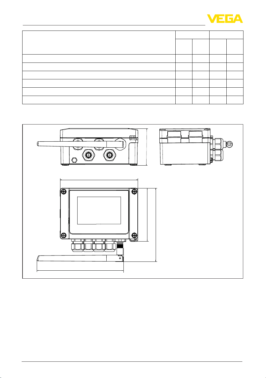
44
14 Supplement
VEGAMET Air 841 • LoRaWAN
1104032-EN-260703
Functions VEGAMET Air Adjustment
141
841
142
842
OP DTM/
App
Simulation - Sensor value, %, lin% value, scaled values • • • •
Simulation - current output • • •
Simulation - relay output • • •
Protection of the parameterization • • • •
Bluetooth access code • • • •
Activate/deactivate Bluetooth communication • • •
14.3 Dimensions
162 mm
(6.38")
180 mm
(7.09")
76 mm
(2.99")
11 1 mm
(4.37")
153 mm
(6.02")
Fig. 12: Dimensions VEGAMET Air 841
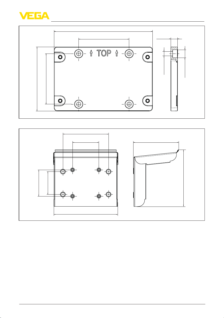
45
14 Supplement
VEGAMET Air 841 • LoRaWAN
1104032-EN-260703
82 mm
(3.23")
11 mm
(0.43")
160 mm
(6.30")
82 mm
(3.23")
104 mm
(4.09")
ø13 mm
(0.51")
ø7 mm
(0.27")
Fig. 13: Dimensions mounting plate
82 mm
(3.23")
142 mm
(5.59")
198 mm
(7.80")
71 mm
(2.76")
82 mm
(3.23")
ca. 141 mm
(5.55")
ca. 177 mm
(6.97")
Fig. 14: Dimensions sun shade
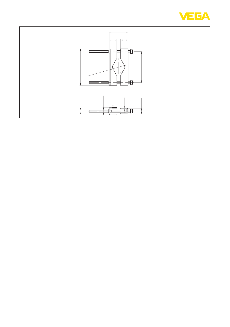
46
14 Supplement
VEGAMET Air 841 • LoRaWAN
1104032-EN-260703
ø 29...60 mm
(1.14"...2.36")
82 mm
(3.23")
15 mm
(0.59")
97 mm
(3.82")
20 mm
(0.79")
M6
2 mm
(0.08")
20 mm
(0.79")
2 mm
(0.08")
20 mm
(0.79")
48...84 mm
(1.89"...3.31")
Fig. 15: Dimensions Brackets for tube mounting

47
14 Supplement
VEGAMET Air 841 • LoRaWAN
1104032-EN-260703
14.4 Industrial property rights
VEGA product lines are global protected by industrial property rights. Further information see
www.vega.com.
VEGA Produktfamilien sind weltweit geschützt durch gewerbliche Schutzrechte.
Nähere Informationen unter www.vega.com.
Les lignes de produits VEGA sont globalement protégées par des droits de propriété intellec-
tuelle. Pour plus d'informations, on pourra se référer au site www.vega.com.
VEGA lineas de productos están protegidas por los derechos en el campo de la propiedad indus-
trial. Para mayor información revise la pagina web www.vega.com.
Линии продукции фирмы ВЕГА защищаются по всему миру правами на интеллектуальную
собственность. Дальнейшую информацию смотрите на сайте www.vega.com.
VEGA系列产品在全球享有知识产权保护。
进一步信息请参见网站<www.vega.com。
14.5 Licensing information for open source software
Open source software components are also used in this device. A documentation of these compo-
nents with the respective license type, the associated license texts, copyright notes and disclaimers
can be found on our homepage.
14.6 Trademark
All the brands as well as trade and company names used are property of their lawful proprietor/
originator.

Printing date:
VEGA Grieshaber KG
Am Hohenstein 113
77761 Schiltach
Germany
1104032-EN-260703
All statements concerning scope of delivery, application, practical use and operat-
ing conditions of the sensors and processing systems correspond to the information
available at the time of printing.
Subject to change without prior notice
© VEGA Grieshaber KG, Schiltach/Germany 2026
Phone +49 7836 50-0
E-mail: [email protected]
www.vega.com