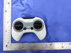

ALINK
1
2
3
5
4
6
7 8 9 10 11 12
User Guide
V1.6
1. Linking Button
2. Indicator Light
3. Type-C
4. Antenna
5. Power Button
6. Control Joystick
7. SD Momentary Button
8. S1 Limit Roller
9. SC 3-position Switch
10. SB 3-position Switch
11. SE Latching Button
12. SA Momentary Button
Part Name
This product is equipped with a built-in ELRS 2.4GHz RF module and a 10-
channel RC model remote controller. It can be used to control any RC model
equipped with an ELRS 2.4GHz receiver.
CADDXFPV Alink Remote Controller Operating Instructions
① Power Button
The round button on the right side of the front panel of the remote controller is the power
button. The operation method is as follows:
② Linking:
④ Joystick Layout
The product is factory-set to Mode 2 (American style), with the first four channels in the order
A, E, T, R, as shown below:
1) When the remote controller is off, short press the power button to display the remaining
battery level (refer to the indicator lights).
2) When the remote controller is off, long press the power button. When the four lights turn
on in sequence and remain solid, and the “do-re-mi, do-mi” sound is heard, the controller is
powered on.
3) When the remote controller is on, short press the power button to mute the receiver
disconnect alert sound. When the remote controller is on, long press the power button. When
the four lights turn off in sequence and the “mi-re-do” sound is heard, the controller is
powered off.
1) [CH1] — AIL: Controls roll, causing the Drone to move left or right during flight.
2) [CH2] — ELE: Controls pitch, causing the Drone to move forward or backward during flight.
3) [CH3] — THR:Controls the throttle, causing the Drone to ascend or descend during flight.
4) [CH4] — RUD: Controls yaw, causing the Drone to turn left or right during flight.
Note: In POSHOLD mode, the throttle is incremental—center for hover, push up to ascend,
push down to descend. In Angle mode and Acro mode, the throttle is direct—how much
you push determines motor speed. Precise throttle control is required to operate the
Drone in these modes.
CH3
Thr
YawCH4
CH2
Pitch
CH1
Roll
Battery Life and Charging Operations
⑤ Function Switches
In addition to the four joystick channels, this product provides six extra channels for use: five
buttons on the front panel of the remote controller and one rotary knob. The corresponding
functions for these switches are pre-configured at the factory, as shown below:
⑥ FPV Simulator
This product can be directly connected to a computer using a Type-C data cable. The Type-C
port is located at the center of the back of the remote controller. Once connected, you can use
an FPV simulator for practice.
① Battery Level Indicator
Located at the center of the front panel of the remote controller, there are four indicator
lights. When powered on, they display the remaining battery level by default. From left to
right, the four lights indicate:
② Battery Life
When fully charged, the remote controller can operate for approximately 3 hours. If left inactive
for a long time, it will emit two short “beep-beep” sounds at intervals, and the indicator lights
will flash. When the battery is low, it will beep intermittently. At this point, the remote should
be charged promptly to avoid automatic shutdown during use, which could cause the Drone
to lose control.
③ Charging
When the remote controller is powered off, it can be charged using the included power adapter
and Type-C cable. During charging, the power status can be monitored via the battery level
indicator lights.
1) SA — Spring-loaded Button (CH6): Used to activate the buzzer function
(Emits two “mi-mi” beeps when powered on, and a “do” beep when powered off)
2) SB — 3-Position Toggle Switch (CH7): Used to switch modes
(Three-position mode corresponds to low, mid, and high levels. Upon power-on, the low
level is indicated by “do”, the mid level by “re-re”, and the high level by “mi-mi-mi”)
3) SC — 3-Position Toggle Switch (CH8): Used to adjust the rate in Acro (ACRO) mode
(Three-position mode corresponds to low, mid, and high levels. Upon power-on, the low
level is indicated by “do”, the mid level by “re-re”, and the high level by “mi-mi-mi”)
4) SD — Spring-loaded Button (CH9): Used to toggle the Turtle (FLIP) mode
(Emits two “mi-mi” beeps when powered on, and a “do” beep when powered off)
5) SE — Latching Switch (CH5): Used to arm/disarm
(Emits two “mi-mi” beeps when powered on, and a “do” beep when powered off)
6) S1 — Limited Rotary Wheel (CH10)
Please note the mode switching and turtle mode functions (refer to Protos Manual > 3.
Instructions > 3.1 PROTOS > 3.1.6 Function Mode ④). Please test these functions in a safe
operating environment (refer to Protos Manual > 2. Pre-Use Preparation > 2.1 Safety
nstructions / 2.2 Usage Limitations). Thank you for your attention.
(1)10-25% (2) 26-50% (3) 51-75% (4) 76-100%
A solid light indicates the current battery range, while a flashing light indicates the battery
is approaching the threshold of that range.
Precautions / Important Notes
Declaration for Micro-power Short-range Devices
Product Specification
① Located at the center of the front panel of the remote controller is a small oval hole, which
serves as the buzzer sound outlet. Do not insert sharp objects into this hole, as it may damage
the buzzer.
② The gray elongated area at the center of the front panel is the cover for the extension
antenna. Installing other high-gain antennas requires removing the back cover of the remote
controller. If you are a beginner or not an experienced user, we do not recommend installing
other antennas yourself. Any consequences resulting from such attempts are not the
responsibility of CADDXFPV, please be aware.
① Compliance with specific clauses and usage scenarios outlined in the "Catalog and Technical
Requirements for Micro-power Short-range Radio Transmission Equipment," including the types
and performance of antennas used, as well as methods for control, adjustment, and switching.
② Unauthorized changes to usage scenarios or conditions, expansion of transmission frequency
ranges, increase of transmission power (including the addition of external RF power amplifiers),
and modification of transmission antennas are prohibited.
③ The device must not cause harmful interference to other lawful wireless stations, nor shall it
claim protection against such interference.
④ The device must tolerate interference from industrial, scientific, and medical (ISM) applications
emitting radio frequency energy, as well as interference from other lawful wireless stations.
⑤ If harmful interference is caused to other lawful wireless stations, use of the device must
cease immediately and may only resume after measures have been taken to eliminate the
interference.
⑥ When using micro-power devices within electromagnetic protection areas, radio astronomy
observatories, meteorological radar stations, satellite earth stations (including tracking,
telemetry, control, ranging, reception, and navigation stations), and military or civilian wireless
stations delineated by laws, regulations, national standards, or related provisions,
compliance with electromagnetic protection requirements and regulations of the relevant
industry authorities is mandatory.
⑦ The use of all types of model remote controllers is prohibited within a 5,000-meter radius
centered on the airport runway.
⑧ Environmental conditions, such as temperature and voltage, during the operation of micro-
power devices must be adhered to.
Model
FCC ID
Main Control Chip
RF Module
RF Protocol
Number of Available Channels
Joystick Type
Function Switch
Status Indicator Module
Charging & Communication Interface
Battery Specification
Max Charging Power
Charging Time
Operating Voltage Range
Dimensions
Weight
C0PJ-YK021
2BHG9-C0PJ-YK021
AT32 F413RCT7
ELRS 2.4GHZ
CRSF
10 Channels (including 4 joystick channels)
Full-Bearing Hall-Sensor Joystick Assembly
1 x Latching Button / 2 x Momentary Buttons /
2 x 3-Position Toggle Switches / 1 x Scroll Wheel
4 x Status Indicator LEDs / Buzzer
USB-Type C
Lipo 1s 1000mAh
5V / 1A / 3.50W
≈90:00 min
DC 3.50V~4.20V
158mmx108mmx68mm
180g±5g
This equipment has been tested and found to comply with the limits for a Class B digital device, pursuant
to Part 15 of the FCC Rules. These limits are designed to provide reasonable protection against harmful
interference in a residential installation. This equipment generates uses and can radiate radio frequency
energy and, if not installed and used in accordance with the instructions, may cause harmful interference
to radio communications. However, there is no guarantee that interference will not occur in a particular
installation. If this equipment does cause harmful interference to radio or television reception, which can
be determined by turning the equipment off and on, the user is encouraged to try to correct the
interference by one or more of the following measures:
-- Reorient or relocate the receiving antenna.
-- Increase the separation between the equipment and receiver.
-- Connect the equipment into an outlet on a circuit different from that to which the receiver is connected.
-- Consult the dealer or an experienced radio/TV technician for help.
This device complies with part 15 of the FCC Rules. Operation is subject to the following two conditions:
(1) This device may not cause harmful interference, and (2) this device must accept any interference
received, including interference that may cause undesired operation.
Changes or modifications not expressly approved by the party responsible for compliance could void the
user's authority to operate the equipmen.
* RF warning for Portable device:
The device has been evaluated to meet general RF exposure requirement. The device can be used in
portable exposure condition without restriction.
FCC ID 2BHG9-C0PJ-YK021
12
1) Press and hold the power switch to turn on the
remote controller;
2) Press and hold the bind button until the buzzer
emits two “mi-mi” beeps.
③ Calibration:
1) With the power off, return all sticks to the
center position (limit wheels do not require
calibration).
2) Briefly press the bind button and the power
button at the same time. The buzzer will emit
three beeps (“do-mi-do”) to enter calibration
mode.
3) After entering calibration mode, do not
operate the sticks. The status LEDs will flash
while the center points are being calibrated.
Once center-point calibration is complete, the
buzzer will emit two beeps (“do-mi-do”), and the status LEDs will turn off.
4) Move the sticks through their full travel (this can be done simultaneously). During
movement, the status LEDs will light up sequentially according to the stick travel,
activating the corresponding channel LEDs (for example, when throttle calibration is
completed, the third LED from left to right will light up).
5) When all status LEDs are lit, calibration is complete. Press and hold the power button
to power off and save the settings.