
VCC
GND
RX
TX
GND
SBUS
1.Camera
2.Fan
3.Power Port
Power Consumption Reference: 12V @ 1.5A.
Please consider the power supply capacity when wiring.
The product generates significant heat during operation.
Ensure proper airflow for cooling.
1.Connect the Ascent GT PRO and the Ascent Goggles.
2.Short-press the frequency pairing button on both the Ascent GT PRO
and the Ascent Goggles. When the Ascent GT PRO enters pairing
mode, the VTX LED will light solid red, and the goggles will emit a beep
pattern: DI…DI…DI…
3.Once the connection is successful, the VTX LED will turn solid green,
the beeping from the goggles will stop, and the video image will be
displayed.
Introduction
Connection
Linking
Ascent GT PRO
Quick Start Guide
V1.0
4.VTX LED
5.Link Button
6.Gimbal Port
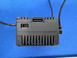
7.Type-C Port
8.Antenna
By connecting the VTX serial port to the FC, you can access the FC OSD
information. Using Betaflight Configurator 10.10.0 with firmware version
4.5.0 as an example, the serial port configuration method is described
below.
1.Solder the blue and green wires from the 6-pin power cable to the
UART1 port on the FC (refer to the connection page). Here, UART1 is
taken as an example.
2.Connect the FC to Betaflight Configurator, open the corresponding
UART port, check the MSP option, and enable VTX (MSP + Displayport).
3.On the Presets page, search for Avatar OSD or HD OSD and click to
select it.
4.On the OSD page, configure the information you want to display.
2. Open the CLl command line and enter the content in red font,
“set osd_displayport_device = MSP”
“set vcd_video_system = HD”
“save”
Goggles Buzzer Status
Link state
upgrade firmware
Upgrade failed
VTX Indicator Status
Link state
upgrade frmware
Wireless not connected
Wireless connection,
image output is normal
Wireless connection is normal,
image is abnormal
DI.....DI....DI...
DI..........DI...... DI——
DI..DI..DI..
Steady red light
Red light rapidly flashes
Steady green light
green light rapidly flashes
green light slowly flashes
1.Open the corresponding uart port (Take uart1 as an example in the figure
Check the MSP switch and click Save, Check the VTX (MSP+Displayport)。
FC OSD
Name
Communication Frequency
Communication Bandwidth
1. Before powering on, please install all antennas to avoid damage to
components.
2. When the standby mode is turned on, the power is limited to 7.05mW.
Prior to use you need to unlock the FC or turn off the standby mode.
3. If you use it with other 5.8GHz devices at the same time, please choose
a different channel.
4. lf you use the Gyroflow function of the camera, please provide shock
absorption for the fxed deck of the camera to avoid the failure of the
anti-shake.
Transmitter Power (EIRP)
l/O Interface
Image Quality
Auto Frequency
Manual Frequency
Channels
Wide Power Input
Mounting Holes
Dimensions
Operating Temperature
Supports FC System
Supports FPV Goggles
and Remote Controller
OSD
Latency
Antenna
Canvas mode
Average delay 35ms
Ascent GT PRO VTX
5.740-5.805 GHz
5 / 20 MHz
8.48dBm
SH1.0-6P,TYPE-C, Gimbal Port SH1.0-2P
1080P 60FPS
Support
Support
3
11.1V-25.2V
20*20mm; 25.5*25.5mm
34*34*22.6mm
-10℃~40℃
BetaFlight / INAV / Ardupilot
Goggles Ascent / Goggles Cine
2 (MMCX)
Name
Image Sensor
Resolution
Ratio
Lens
FOV
Aperture
Shutter
Weight
Dimensions
Minimum Illumination
Coaxial Cable
AVATAR Pro V2 Camera
1/1.8-Inch sony starvis II sensor
1080P/60fps; 720P/60fps
16/9
8Mp
147°
F1.0
Rolling Shutter
9.5g
19*19*24mm
0.00001Lux
140mm
Precautions
VTX Specification
Camera Specification
Betaflight 4.4 or above version settings:
Status indication
Failsafe
Presets
Presets
OSD for Fpv.wtf, FJI O3, Avatar HD
Categories
Select...
Avatar osd
Keywords
Select...
Authors
Select...
PID Tuning
Receiver
Modes
Adjustments
Community
Author:
Firmware:
Keywords:
VTX
benlumley
4.4; 4.5
vtx; dji; O3 air unit; O3; 03; avatar; walksnail; HD; HD video; vista; air unit; fpv.wtf; wtfos; msp-osd; displayport; msp; sugarK
VTX (MSP+Displayport)
When upgrading the Ascent VTX, connect it to your computer using a
Type-C USB cable. Then, open the Caddx_PC_Tool on your computer.
Once the USB connection is established, follow the on-screen
instructions to select the firmware file Ascent_G_Sky_XX_X_XX.img for
the upgrade.
Note:
1. When the Ascent VTX is connected to the computer via Type-C, no
external battery power is required — the computer’s USB port will
supply power to the module.
2. Do not disconnect the USB cable during the upgrade process. Unplug
the cable only after the upgrade has completed successfully.
1. Click the Ascent Sky KIT connection option.
2. Click the Select button to open the pop-up window, choose the
corresponding firmware version, then click Open to start the upgrade
process.
3. Do not restart or power off the device during the upgrade process to
avoid upgrade failure.
4. Upgrade completed.
Caddx PC Tool
Version: V1.1.5
Firmware Upgrade
Ascent Sky KIT Disconnect
HardwareVer:
SN:
Firmware:
Temperature:
FPV-Edu-Sky-485-V2.0
0001
Ascent_G_Sky_16_1_30
69℃
FAQ
Setting
2025 Caddx Technology (shenzhen) Co., Ltd.
Ascent_G_Sky_16_1_30.img
Upgrading, do not restart ro turn power off!
Select Upgrade
Caddx PC Tool
Version: V1.1.5
Firmware Upgrade
Ascent Sky KIT Disconnect
HardwareVer:
SN:
Firmware:
Temperature:
FPV-Edu-Sky-485-V2.0
0001
Ascent_G_Sky_16_1_30
69℃
FAQ
Setting
2025 Caddx Technology (shenzhen) Co., Ltd.
100%
Upgrade finished!
Select Upgrade
Caddx PC Tool
Version: V1.1.5
Firmware Upgrade
Ascent Gnd KIT Disconnect
HardwareVer:
SN:
Firmware:
Temperature:
FPV-Edu-Gnd-485-V2.0
1234567890
Ascent_G_Gnd_16_1_30
52℃
FAQ
Setting
2025 Caddx Technology (shenzhen) Co., Ltd.
Please Load The Firmware
Select Upgrade
Open
<< tool > Ascent GT Upgrade > Ascent VTX update Image
组织 新建文件夹
Ascent_G_Sky_16_1_30.img
Ascent_G_Sky_16_1_30.img
All Files (*)
打开 (O) 取消
文件名(N):
1
2
3
4
Caddx PC Tool
Version: V1.1.5
Firmware Upgrade
FAQ
Setting
2025 Caddx Technology (shenzhen) Co., Ltd.
Ascent Sky KIT
Connect

FCC
This equipment has been tested and found to comply with the
limits for a Class B digital device, pursuant to Part 15 of the FCC
Rules. These limits are designed to provide reasonable protection
against harmful interference in a residential installation. This
equipment generates uses and can radiate radio frequency
energy and, if not installed and used in accordance with the
instructions, may cause harmful interference to radio
communications. However, there is no guarantee that
interference will not occur in a particular installation. If this
equipment does cause harmful interference to radio or television
reception, which can be determined by turning the equipment off
and on, the user is encouraged to try to correct the interference
by one or more of the following measures:-- Reorient or relocate
the receiving antenna.
-- Increase the separation between the equipment and receiver.
-- Connect the equipment into an outlet on a circuit different from
that to which the receiver is connected.
-- Consult the dealer or an experienced radio/TV technician for
help.
This device complies with part 15 of the FCC Rules. Operation is
subject to the following two conditions:
(1) This device may not cause harmful interference, and (2) this
device must accept any interference received, including
interference that may cause undesired operation.
Changes or modifications not expressly approved by the party
responsible for compliance could void the user's authority to
operate the equipment
*RF warning for Mobile device:
This equipment complies with FCC radiation exposure limits set
forth for an uncontrolled environment. This equipment should
be installed and operated with minimum distance 20cm between
the radiator & your body.