
Radiolink Electronic Ltd
www.radiolink.com
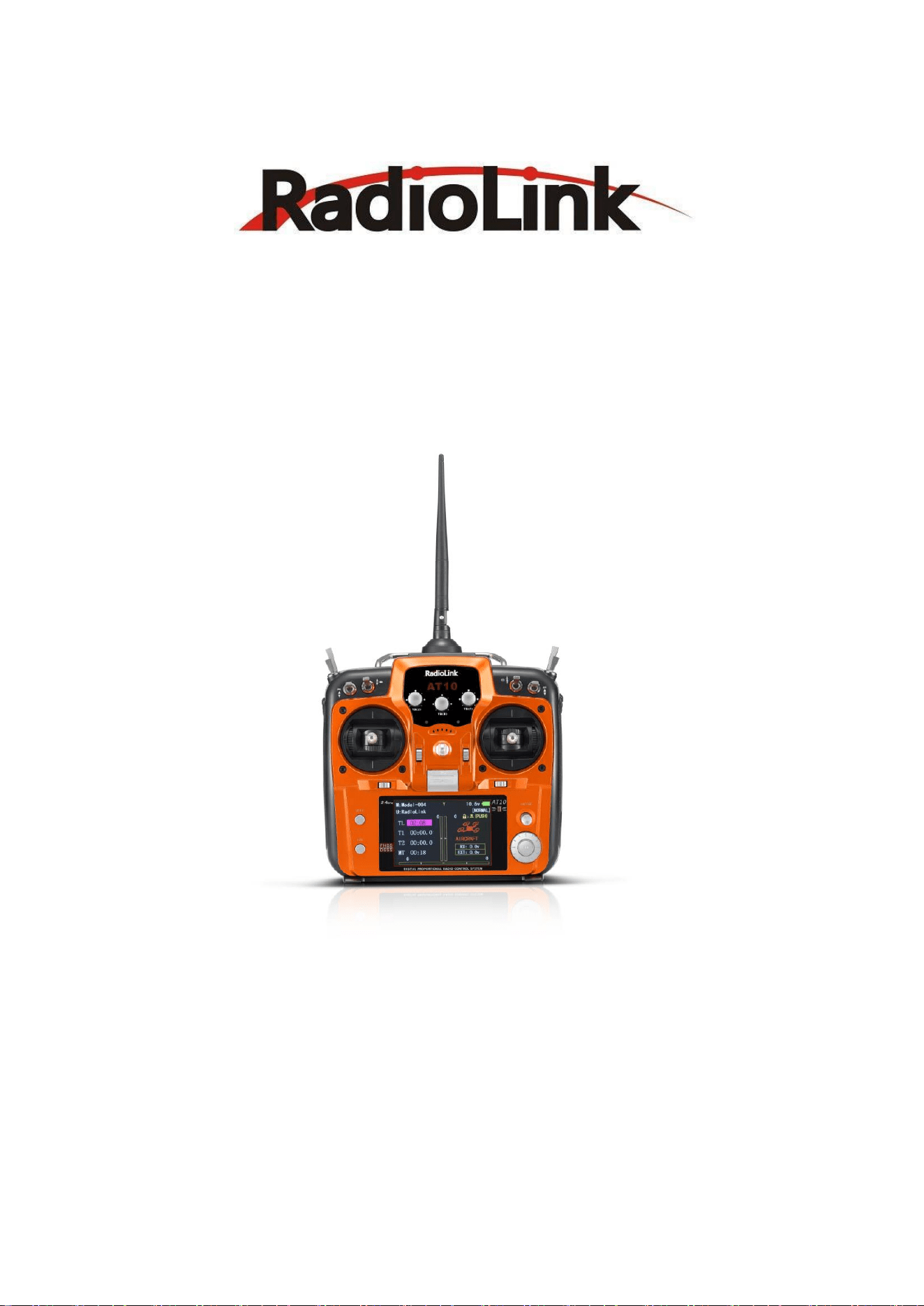
Thank you for purchasing RadioLink 12-channel remote controller AT10II.
To fully enjoy the benefits of this product and ensure safety, please read the manual carefully and set up
the device as instructed steps.
If any problems found during the operation process, either way listed below can be used as online tech
support.
1. Send mails to after_service@radiolink.com.cn and we will answer your question at the earliest.
2. PM us on our Facebook page or leave comments on our YouTube page
3. If the product is purchased from the local distributor, you can also ask them for support and repair as
prefer.
All manuals and firmware are available on RadioLink official website www.radiolink.com and more tutorials
are uploaded. Or follow our Facebook and YouTube homepage to stay tuned with our latest news.
SAFETY PRECAUTIONS
⚫ Never operate models during adverse weather conditions. Poor visibility can cause disorientation and
loss of control of pilots’ model.
⚫ Never use this product in a crowd or illegal areas.
⚫ Always check all servos and their connections prior to each run.
⚫ Always be sure about turning off the receiver before the transmitter.
⚫ To ensure the best radio communication, please enjoy the flight/driving at the space without
interference such as high voltage cable, communication base station or launching tower.
WARNING
This product is not a toy and is NOT suitable for children under the age of 14. Adults should keep the
product out of the reach of children and exercise caution when operating this product in the presence of
children.
Water or moisture may enter the transmitter inside through gaps in the antenna or joystick and cause model
instability, even out of control. If running in the wet weather (such as game) is inevitable, always use plastic
bags or waterproof cloth to cover the transmitter.
FCC Statement
This equipment has been tested and found to comply with the limits for a Class B digital device, pursuant to
Part 15 of the FCC Rules. These limits are designed to provide reasonable protection against harmful
interference in a residential installation. This equipment generates uses and can radiate radio frequency
energy and, if not installed and used in accordance with the instructions, may cause harmful interference to
radio communications. However, there is no guarantee that interference will not occur in a particular
installation. If this equipment does cause harmful interference to radio or television reception, which can be

Radiolink Electronic Ltd
www.radiolink.com
determined by turning the equipment off and on, the user is encouraged to try to correct the interference by
one or more of the following measures:
-- Reorient or relocate the receiving antenna.
-- Increase the separation between the equipment and receiver.
-- Connect the equipment into an outlet on a circuit different from that to which the receiver is connected.
-- Consult the dealer or an experienced radio/TV technician for help.
This device complies with part 15 of the FCC Rules. Operation is subject to the following two conditions:
(1) This device may not cause harmful interference, and (2) this device must accept any interference
received, including interference that may cause undesired operation.
Changes or modifications not expressly approved by the party responsible for compliance could void the
user's authority to operate the equipment.

Radiolink Electronic Ltd
www.radiolink.com
CONTENT
1 Part 1. INTRODUCTION OF AT10II SYSTEM ............................................................... 1
1.1 AT10II SYSTEM ................................................................................................. 1
1.1.1 Function of transmitter ........................................................................................ 1
1.1.2 Transmitter Panel Shows: ................................................................................... 2
1.1.3 Compatible receivers .......................................................................................... 4
1.1.4 RSSI testing ....................................................................................................... 4
1.2 RADIO INSTALLATION ...................................................................................... 5
1.2.1 Guidelines to mount the servos, receiver and battery .......................................... 5
1.2.2 Receiver and servo connections ......................................................................... 7
1.2.3 Installment of antenna ...................................................................................... 10
1.3 RADIO BASIC SETTING ................................................................................... 11
1.3.1 Basic setting of the transmitter ........................................................................... 11
1.3.2 Model type ......................................................................................................... 11
1.3.3 Binding .............................................................................................................. 11
1.3.4 Transmitter Displays & Buttons .......................................................................... 11
2 PART 2. BASIC FUNCTION OF AIRPLANE ............................................................... 13
2.1 QUICK GUIDE OF ACRO BASIC MENU........................................................... 13
2.2 QUICK GUIDE: GETTING STARTED WITH A BASIC 4-CHANNEL AIRPLANE . 14
2.3 AIRPLANE BASIC FUNCTION ......................................................................... 16
2.3.1 Model Select..................................................................................................... 16
2.3.2 Model Type ....................................................................................................... 17
2.3.3 End Point of servo travel adjustment (END POINT, also called EPA) ................. 19
2.3.4 Trim .................................................................................................................. 20
2.3.5 SUB TRIM ........................................................................................................ 20
2.3.6 Servo Reversing (REVERSE): .......................................................................... 21
2.3.7 Dual/triple rates and exponential (D/R,EXP) ...................................................... 22
2.3.8 Throttle Cut ...................................................................................................... 25
2.3.9 IDLE DOWN (ACRO only) ................................................................................ 26
2.3.10 Fail Safe (F/S)............................................................................................... 27
2.3.11 Auxiliary Channel Function (including channel 9-10 controls) ........................ 28
2.3.12 TIMER submenu (stopwatch functions): ........................................................ 29
2.3.13 TRAINER: ..................................................................................................... 30
2.3.14 Logic Switch Selection (LOGIC SW): ............................................................. 31
2.3.15 SERVO display and cycle submenu: ............................................................. 32
2.3.16 TELEMETARY .............................................................................................. 32
3 Part 3. ACRO ADVANCE MENU FUNCTIONS ......................................................... 34
3.1 AIRPLANE WING TYPES (ACRO/GLID): ......................................................... 34
3.2 TWIN AILERON SERVOS (5-channel receiver, AILE-2 , ACRO/GLID) ............... 35
3.3 ACRO ADVANCE FUNCTION MENU ............................................................... 35
3.3.1 Program MIX .................................................................................................... 36
3.3.2
Curve Programmable Mixes (PROG.MIX5-8)(HELI: PROG.MIX5-6 ):
................ 39
3.3.3
Flaperon (ACRO/GLID 1A+1F ):
....................................................................... 40
3.3.4 FLAP-TRIM ...................................................................................................... 41
3.3.5 AILE DIFF (ACRO/ GLID 2A+1F/ GLID 2A+2F) ................................................ 42
3.3.6
Air Break (ACRO/ GLID)
................................................................................... 43
3.3.7
ELEV-FLAP mixing (ACRO/GLID):
.................................................................... 44
3.3.8
Dual Elevator Servos (with a rudder) (AILEVATOR) (ACRO):
............................ 45
3.3.9 Snap Rolls (ACRO)........................................................................................... 46
3.3.10 V-Tail (ACRO/ GLID) ..................................................................................... 47
3.3.11 ELEVON ....................................................................................................... 48
3.3.12 Gyro Sense ................................................................................................... 49
3.3.13 THR-DELAY (ACRO): ................................................................................... 50

Radiolink Electronic Ltd
www.radiolink.com
3.3.14 THR CURVE (ACRO) ................................................................................... 50
3.3.15 THROTTLE-NEEDLE mixing (ACRO/ HELI): ................................................. 51
4 PART 4 GLIDER MODEL FUNCTIONS ....................................................................... 53
4.1 SET BASIC MENU OF GLID............................................................................. 53
4.2 SET GLID TYPE ............................................................................................... 54
4.3 GLID ADVANCE MENU .................................................................................... 55
64.3.1 AILE DIFF (FIND IN ACRO FUNCTION MENU 3.3.5) ....................................... 56
4.3.2 FLAPERON (GLID 1A+1F, FIND IN ACRO FUNCTION MENU 3.3.3)................ 56
4.3.3 V-TAIL (FIND IN ACRO FUNCTION MENU 3.3.10) ........................................... 56
4.3.4 OFFSET (GLID 2A+2F): ................................................................................... 56
4.3.5
START DELAY (GLID 1A+1F only):
.................................................................. 57
4.3.6
CHAMBER-FLP
................................................................................................ 57
4.3.7
Camber Mixing:
................................................................................................ 58
4.3.8 BUTTERFLY (crow) mixing ............................................................................... 59
4.3.9 AILE/ RUDD MIX .............................................................................................. 60
4.3.10
ELEV-FLAP mixing (see GLID menu 3.3.7)
................................................... 61
4.3.11
AILE-FLAP(GLID 2A+2F only):
...................................................................... 61
4.3.12
SPOILER MIX (GLID):
.................................................................................. 61
4.3.13 FLAP-TRIM (see GLID 3.3.4) ........................................................................ 62
4.3.14 CONDITION ................................................................................................. 62
5 Part. 5 HELICOPTER MODEL FUNCTIONS ............................................................... 63
5.1 BASIC SETTING WITH HELICOPTER ............................................................. 63
5.2 HELI-SPECIFIC BASIC MENU FUNCTIONS .................................................... 66
5.2.1 Swash Plate Types ........................................................................................... 66
5.2.2 SWASH AFR (not in SWH1):............................................................................. 67
5.3 HELI-SPECIFIC ADVANCE MENU FUNCTIONS .............................................. 68
5.3.1 THR-CURVE and PIT-CURVE: ......................................................................... 68
5.3.2 REVO MIX: ....................................................................................................... 69
5.3.3 GYRO SENSE .................................................................................................. 71
5.3.4
THROTTLE HOLD
............................................................................................ 71
5.3.5
HOVERING ADJUSTMENTS (HOV-THR and HOV-PIT):
.................................. 72
5.3.6
HIGH/LOW PITCH (HI/LO-PIT):
........................................................................ 73
5.3.7
OFFSET
........................................................................................................... 74
5.3.8
DELAY
............................................................................................................. 75
5.3.9
GOVERNORS:
................................................................................................. 75
5.3.10
Throttle Mixing (THROTTLE MIX)
................................................................. 77
5.3.11
SWASH-RING
.............................................................................................. 77
5.3.12
THROTTLE NEEDLE (see ACRO MENU 3.3.15)
.......................................... 78
5.3.13
PROG MIX (see ACRO MENU 3.3.1)
............................................................ 78
5.3.14
CONDITION
................................................................................................. 78
6 Part 6. MULTIROTOR FUNCTIONS ............................................................................ 79
6.1 MULTIROTOR BASIC MENU ........................................................................... 81
6.1.1 MODEL TYPE .................................................................................................. 81
6.1.2 AUX Channel setting ........................................................................................ 81
6.2 ADVANCE MENU FOR MULTIROTOR ............................................................. 81
6.2.1 ATTITUDE ........................................................................................................ 81
6.2.2 THROTTLE CURVE (see ACRO 3.3.14) ........................................................... 82
6.2.3 PROG. MIX (see ACRO 3.3.1) .......................................................................... 82
AT10II Using Tutorials............................................................................................................82

Radiolink Electronic Ltd
www.radiolink.com
1
Part 1 INTRODUCTION OF AT10II SYSTEM
Note that in the text of this manual, beginning at this point, any time we are using a feature's
specialized name or abbreviation as seen on the screen of the AT10II, that name, feature, or
abbreviation will be exactly as seen on the radio’s screen, including capitalization and shown in a
DIFFERENT TYPE STYLE for clarity. Any time we mention a specific control on the radio itself,
such as moving SWITCH A, KNOB VR(B), or the THROTTLE STICK, those words will be displayed
as they are here.
1.1 AT10II SYSTEM
1.1.1 Function of transmitter
Aero basic
•V tail •Twin Aileron Servos
•Elev-flap mix •Twin Elevator Servos
•air brake •Snap roll
•Gyro mixing
Glider (3 wing model: 1A+1F/2A+2F/1A+2F)
•V tail •Twin Ailerons
•Elevon •Butterfly
•Offset
•5 flight conditions (normal, start, speed, distance, landing)
•IDLE- DOWN (ACRO), THR-CUT (ACRO HELI) (engine shut off), and MOTOR CUT (GLID) setups
to allow precise engine/motor control for taxi and landings.
•15 model type memory
•New stick design with improved feel, adjustable length and tension.
•Triple rates available by setting dual rates to 3-position switches.
•Eight SWITCHES, 3 DIALS and 2 SLIDERS; completely assignable in most applications.
•Trainer system includes the “functional” (FUNC) setting, which allows the student to use the
AT10II’s mixing, helicopter, and other programming functions even with a 4-channel buddy box.
(Optional trainer cord required.)
•AT10II transmitter features airplane friendly switch layout, with the trainer switch at the left hand
(Mode 2), and a notched throttle to minimize throttle changes with rudder input. Defaults to ACRO
model type.
•AT10II transmitter features helicopter-friendly switch layout, with idle-up and throttle hold switches
at the left hand, and a smooth, ratchet-less (unsprung) throttle for perfect hovering. Defaults to
HELI (H-1 swash plate type) model type
Helicopter (8 swashplate types, including CCPM)
• 3 Idle Ups • Throttle and Pitch Curves per Condition
• Revo. Mixing • Gyro Mixing including Separate Settings per Condition
• Delay • Governor Mixing
MULTIROTOR:
• ATTITUDE (Normal, attitude, GPS, hover, F/S, Aux)
• Throttle curve
• Mix programmable
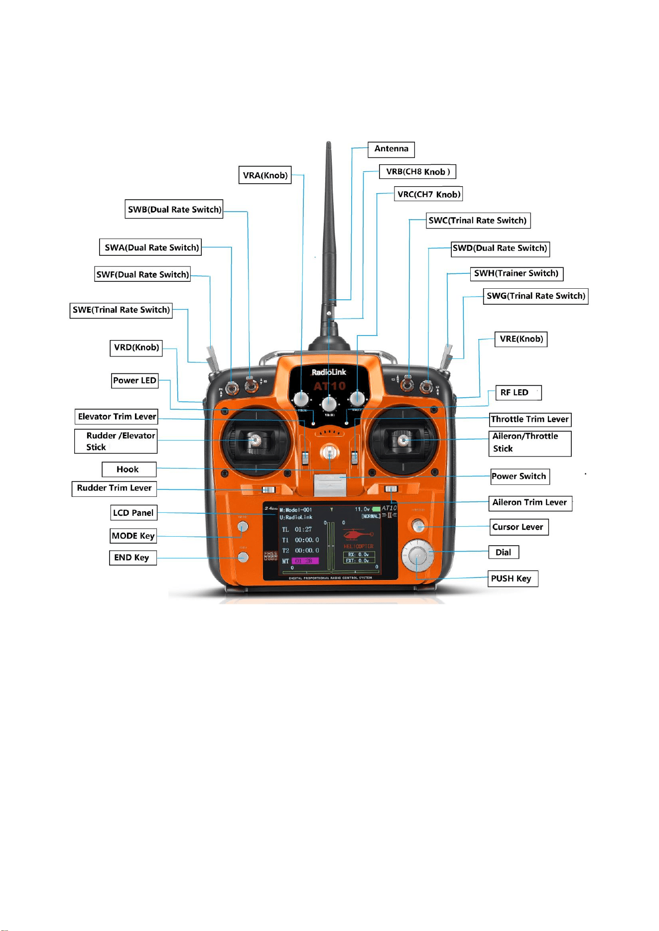
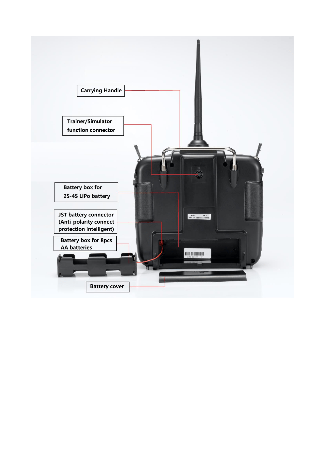
Radiolink Electronic Ltd
www.radiolink.com
3
SWITCH ASSIGNMENT TABLE
• The factory default functions activated by the switches and knobs for a AT10II transmitter are
shown below.
• Most AT10II functions may be reassigned to non-default positions quickly and easily.
Always check that you have the desired switch assignment for each function during setup

Radiolink Electronic Ltd
www.radiolink.com
4
1.1.3 Compatible receivers
AT10II is a 12 channels transmitter, support 2.4G DSSS and FHSS spread spectrum working
Switch/Knob
A or H
Airplane (
ACRO
)
Sailplane/Glider
(
GLID
)
Helicopter (
HELI
)
MULTIROTOR
SWITCH A
CH10
D/R,EXP
-CH2(ELEV)
THR CUT
TIMER
LOGIC SW
CH10
D/R,EXP
-CH2(ELEV)
MOTOR CUT
TIMER
LOGIC SW
down=
BUTTERFLY
on
AIL/RUD-MIX
CH10
D/R,EXP
-CH2(ELEV)
TIMER
LOGIC SW
CH10
D/R,EXP
-CH2(ELEV
)
TIMER
LOGIC SW
SWITCH B
CH9
D/R,EXP
-CH4(RUDD)
CH9
D/R,EXP
-CH4(RUDD)
SPOILER-MIX
CH9
D/R,EXP
-CH4(RUDD)
CH9
D/R,EXP
-CH4(RUDD)
SWITCH C
ADVANCED
MENU-
ELEV-FLAP
up =
ELE-FLP
on
center/down=
IDLE-DOWN
down =
AIRBRAKE
on
up =
ELEV-FLAP
on
center =
CONDITION
Distance
down =
CONDITION
Landing
CH7
GOVERNOR
ATTITUDE
SWITCH D
D/R,EXP
-CH1(AILE)
D/R,EXP
-CH1(AILE)
D/R,EXP
-CH1(AILE)
D/R,EXP
-CH1(AILE)
SWITCH E or
G*
THR- CURVE
down =
CONDITION
Start
up =
CONDITION
Speed
CONDITION
IDLE-UP
THR-CURVE
SWITCH F or
H*
——
——
CH5
GYRO-SENSE
CONDITION
IDLE-UP
——
SWITCH G
or E*
GYRO-SENSE
——
CONDITION
THR-HOLD
——
SWITCH H
or F*
——
.——
THR CUT
MOTOR CUT
KNOB A
CH6
(
flap trim if
FLAPERON
is off)
CH6
CAMBER-FLP
FLAP-TRIM
HOV- PIT
CH6
KNOB B
CH8
CH8
SPOILER-MIX
HOV-THR
CH8
KNOB C
CH7
(disabled if
AIL-DIFF
on)
CH7
HI/LO-PIT
CH7
SLIDER D
——
CH5
——
——
Radiolink Electronic Ltd
www.radiolink.com
5
synchronously, 16 channels pseudo random frequency hopping.
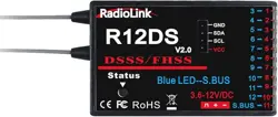
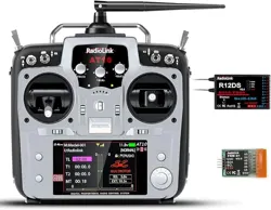
AT10II sells with dual antenna receiver R12DS which support SBUS and PWM signal output
simultaneous, signal coverage all around, never afraid of hilly terrain.
Besides R12DS, AT10II also compatible with Radiolink R6DS, R9DS, R10DS and super mini 10
channels receiver R6DSM and 12 channels mini dual antenna receiver R12DSM.
R6DS, is a 6 channels receiver when working with PWM signal while it is a 10 channels receiver
when working with SBUS or PPM signal.
R9DS, is a 9 channels receiver when working with PWM signal while it is a 10 channels receiver
when working with SBUS signal.
Pay Attention: AT10II is default 12 channels, you have to setup AT10II to 10 channels first if you
use receivers R6DS, R6DSM, R9DS and R10DS.
How to setup to 10 channels transmitter: power on your AT10II--Press Mode button one second to
into BASIC MENU--into SYSTEM menu--change CH-SELECT from 12CH to 10CH.
Since Radiolink radio control systems are not open source, that Radiolink transmitters just
compatible with Radiolink receivers and vice versa.
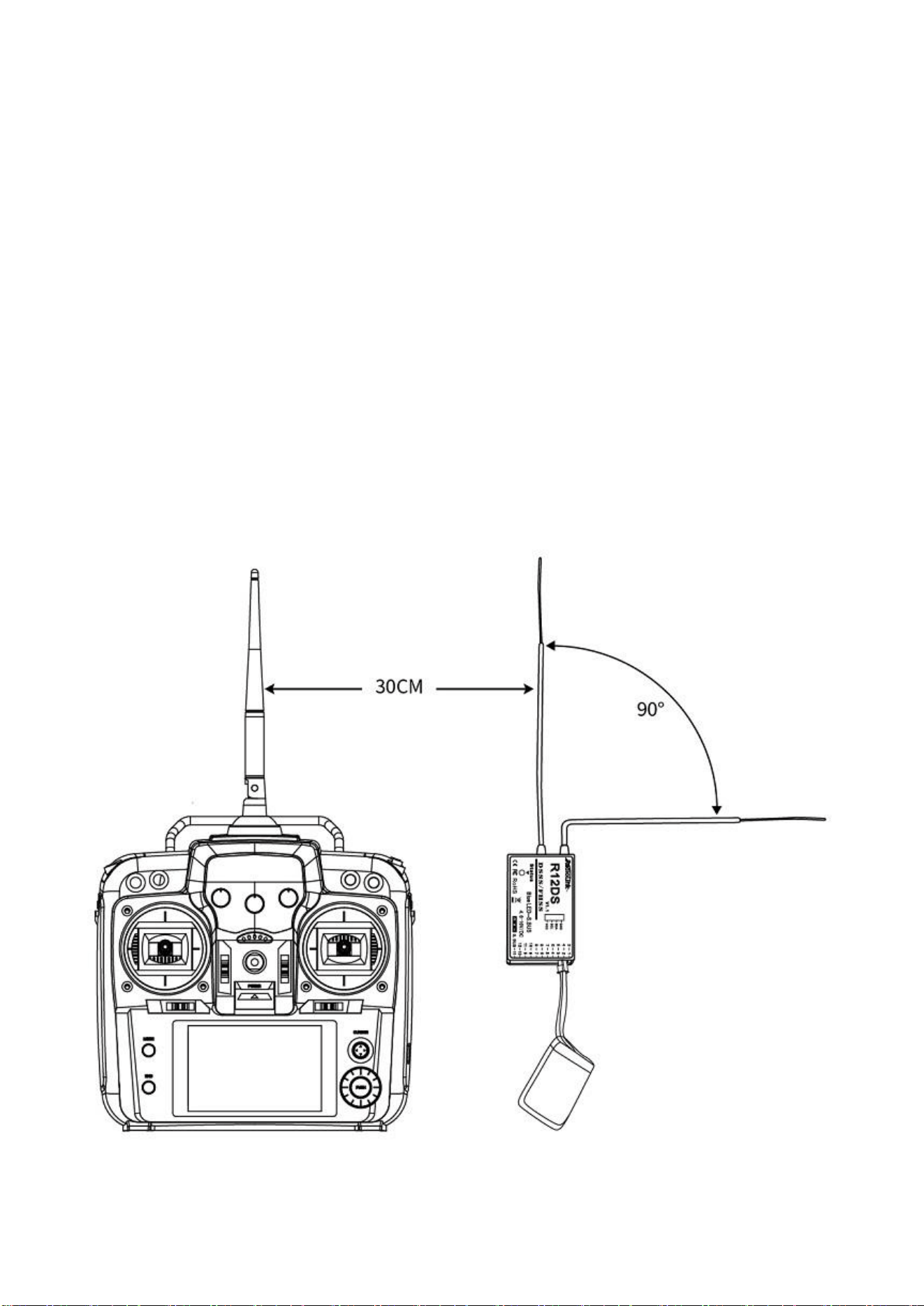
1.1.4 RSSI testing
Power on transmitter and receiver, keep transmitter apart from receiver about 30 centimeters and
the antenna straight.
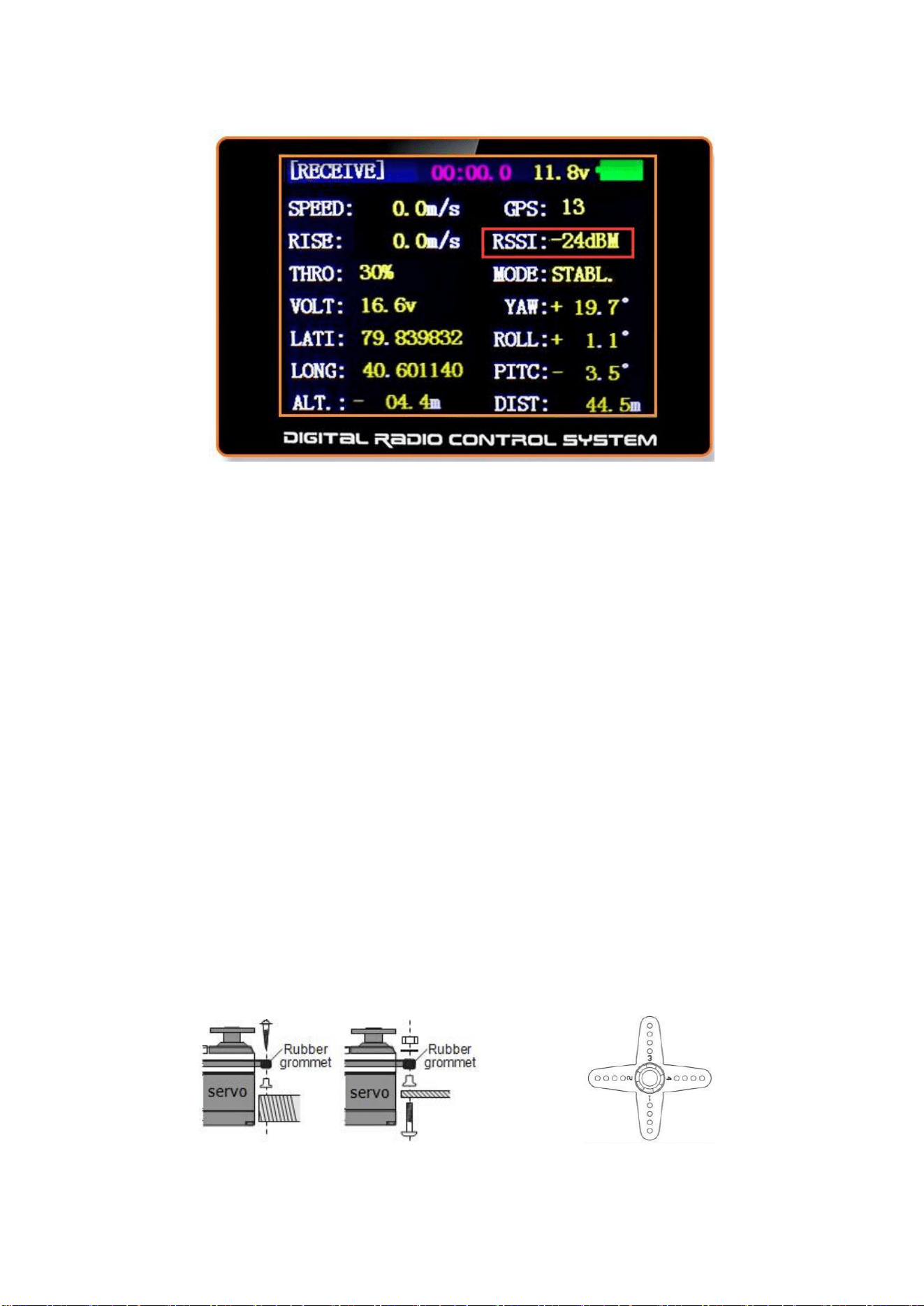
Into the parameter setup menu by press MODE one second, you can check the RSSI in RECEIVE
menu.
The RSSI is 0 to 30dBm is normal when the transmitter is apart about 30 centimeters from the
Radiolink Electronic Ltd
www.radiolink.com
6
receiver, the signal is more better the RSSI data is more close to 0.
1.2 RADIO INSTALLATION
1.2.1 Guidelines to mount the servos, receiver and battery
• Make certain the alignment tab on the battery, switch and servo connectors is orient correctly and
‘key’ into the corresponding notch in the receiver or connectors before plugging them in .When
unplugging connectors, never pull on the wires. Always pull on the plastic connector instead.
• Receiver’s Antenna: In generally receiver’s antenna is longer than remote control, don’t break or
retract it, otherwise shorten the control distance. The antenna must be kept away from conductive
materials, such as metal. Please make distance test before flying.
• If your aileron servos are too far away to plug into the receiver, use an aileron extension cord to
extend the length. Avoid plugging multiple extensions together to obtain your desired length. If the
distance is greater than 50cm or high current draw servos are being used, use heavy servo
extensions.
• Receiver Vibration and Waterproofing: the receiver contains precision electronic part. Be sure to
avoid vibration, shock, and temperature extremes. For protection, wrap the receiver in foam rubber
or other vibration-absorbing materials. It is also a good idea to waterproof the receiver by placing it
in a plastic bag and securing the open end of the bag with a rubber band before wrapping it with
foam rubber. If you accidentally get moisture or fuel inside the receiver, you may experience
intermittent operation or a crash. If in doubt, please contact Radiolink after cares or distributors for
service.
• Always mount the servos with the supplied rubber grommets. Don’t over tighten the screws. No
part of the servo casing should contact the mounting rails, servo tray or any part of structure.
Otherwise, vibration will be transmitted to the servo causing damage of servo. Note the small
numbers (1, 2, 3, and 4) molded into each arm on the servo arms. The number indicate how many
degrees each arm is ‘off’ from 90 degrees to correct for minute manufacturing deviations from servo
to servo.
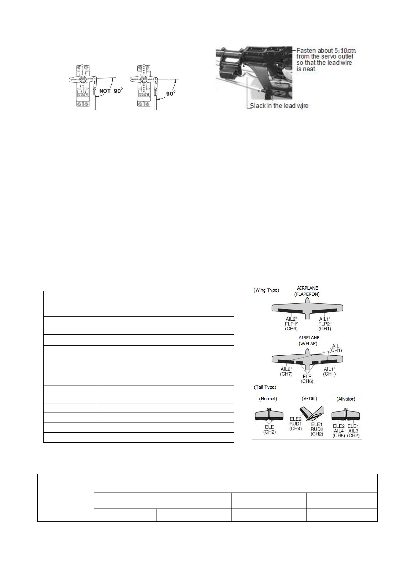
• To center the servos, connect them to receiver and turn on the transmitter and receiver.
Center the trims on the transmitter, then find the arm that will be perpendicular to the pushrod when
placed on the servo.
Radiolink Electronic Ltd
www.radiolink.com
7
• After the servos are installed, operate each servo over its full travel and check that the
pushrods and servo arms don’t bind or contact each other. Also make sure the controls do not
require excess force to operate. If there is an objectionable buzzing sound coming from a servo,
there is probably too much resistance in the control. Find and correct the problem. Even if there is
no servo damage, excess battery drain will result.
• Use the mounting plate from the receiver on/off switch as a template for the cutout and screw
holes, mount the switch on the side of the fuselage opposite the engine exhaust, and where it won’t
be inadvertently turned on or off during handling or storage. Be certain the switch moves without
restriction and ‘snaps’ from ON to OFF, and that the cutout allows full motion of the switch in both
directions.
• When install the switch harness to the helicopter please use the switch cover. Generally,
sandwich the frame between the switch and switch cover and securely tighten the screws, Different
models might require different installations. If so, please follow the model’s instruction manual.
• To prevent the servo lead wires from being broken by vibration during flight, provide a slight
amount of slack or extra so that the wire sticks out slightly and fasten it at suitable points. In addition,
periodically check the wire during daily maintenance.
1.2.2 Receiver and servo connections
(1)Airplane servo connection
Receiver output
and channel
AIRPLANE
1
ailerons/aileron-1¹/combined
flap-2&aileron-1¹
2
elevator
3
throttle
4
rudder
5
spare/landing gear/aileron-2¹
³/combined flap-1 and aileron-2² ³
6
spare/flaps/combined flap-1 and
aileron-2²
7
spare/aileron-2¹
8
spare/elevator-24/mixture control
9
spare
10
spare
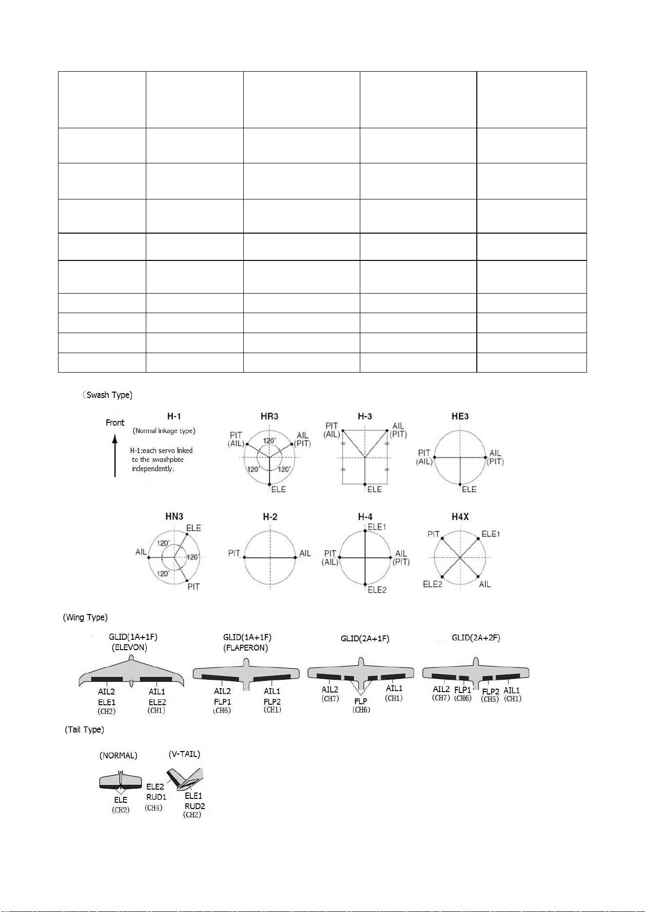
(2)Glider/Sailplane servo connection
RX output & CH
Glider
GLID
(
1
A+
1
F)
GLID (2A+1F)
GLID (2A+2F)
ELEVON
FLAPERON
AILE-DIFF
AILE-DIFF
Radiolink Electronic Ltd
www.radiolink.com
8
1
Combined
elev-2&aileron1
elev-1&aileron-2
Combined flap-2
&aileron-1
aileron-1
Aileron-1
2
Combined
elev-1&aileron-2
Elevator/combined
rudder-2&elev-1¹
Elevator/combined
rudder-2&elev-1¹
Elevator/combined
rudder-2&elev-1¹
3
spare/motor
spare/motor
spare/motor
spare/motor/splr-2¹
4
Rudder
Rudder/combined
rudder-2&elev-2²
Rudder/combined
rudder-2&elev-2²
rudder/combined
rudder-1&elev-2²
5
spare/splr-2¹
spare/spoiler-2¹
spare/spoiler-2¹
flap-2
6
Flaps
Combined
flap-1&aileron-2
flaps
flap-1
7
Spare
spare
ailron-2
Aileron-2
8
spare/splr/splr-1¹
spare/splrs/splr-1¹
spare/splrs/splr-1¹
spare/splrs/splr-1¹
9
Spare
spare
spare
spare
10
Spare
spare
spare
Spare
(3)Helicopter servo connection
Radiolink Electronic Ltd
www.radiolink.com
9
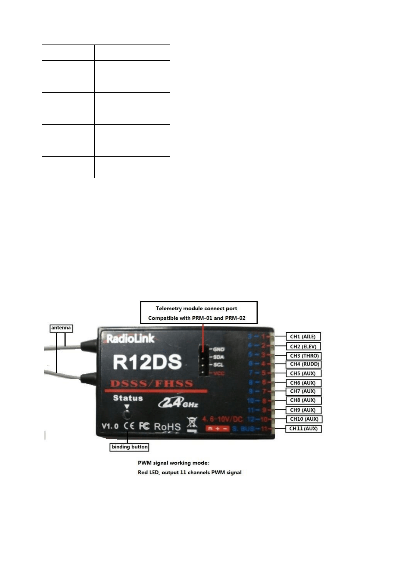
The above listed receiver and channels is referred to the channel 1~11 of the receiver R12DS,
connect the receiver with the related servo, you can control the servos by the correspondent switch.
To be clear, the servo connected with the receiver channel 1 is controlled by the radio aileron lever,
servo connected with channel 2 is controlled by elevator lever, servo connected with channel 3 is
controlled by throttle stick, servo connected with channel 4 is controlled by the rudder lever.
Channel 5~11 can be self-set with the related switches by the menu AUX-CH, and the sub menu.
For SBUS signal channel, is output by the 3 pins of 12 row.
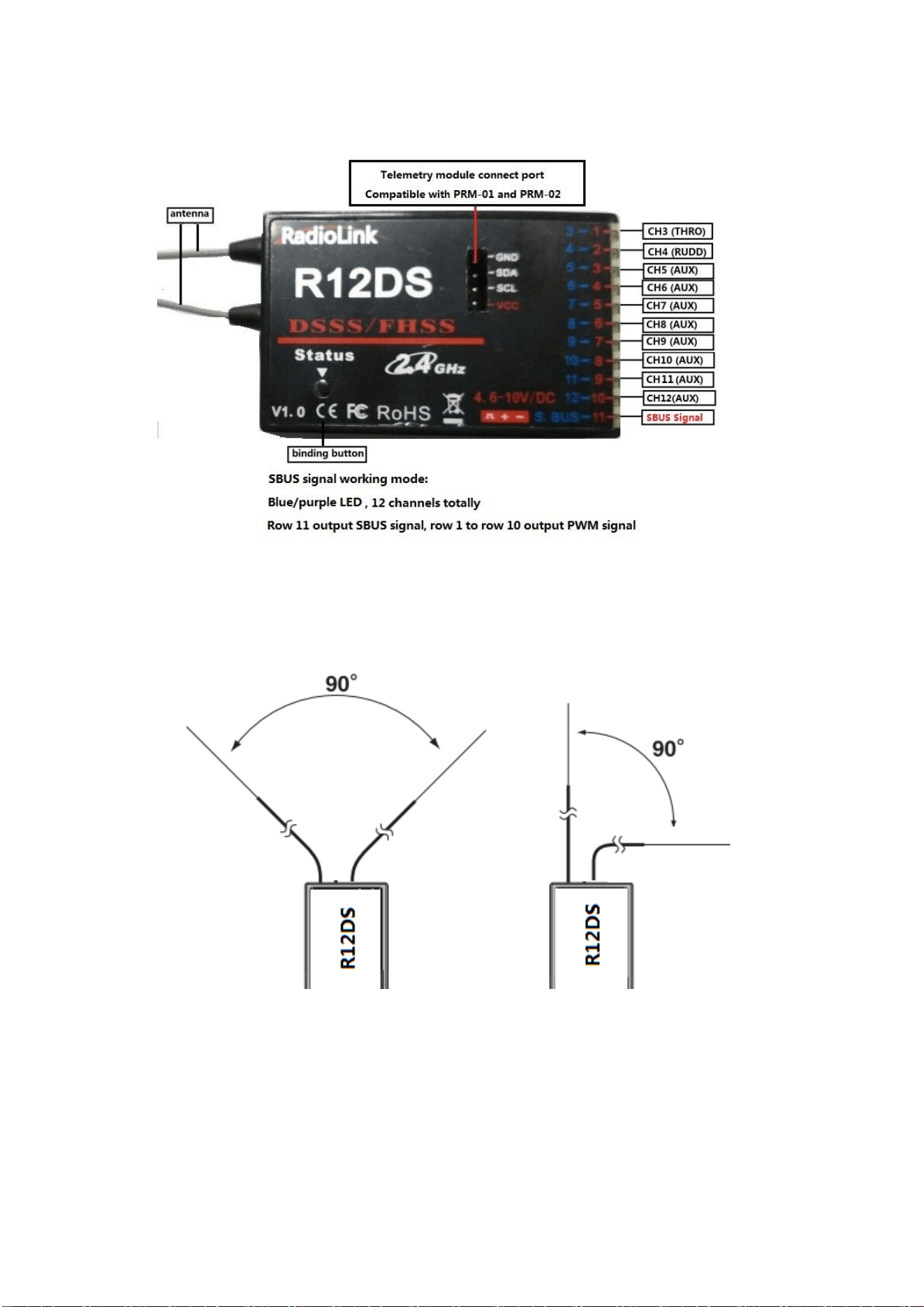
Signal working modes:
There are two signal working modes, PWM and SBUS&PWM signal output. Short press ID SET
twice within 1s, the working mode will change. The RED led indicates the PWM output and
BLUE/PURPLE led indicates SBUS signal.
(1) PWM signal output working mode:RED led indicates PWM signal output, 11 channels totally.
(2) SBUS&PWM dual signal output working mode: BLUE/PURPLE led indicates SBUS&PWM
signal output at the same time with 12 channels totally. SBUS signal channel (3 pin of row 11)
outputs 12 channels of SBUS signal while PWM signal channels (3 pin from row 1 to row 10, i.e.,
CH3 to CH12) output PWM signals with 12 channels in total. The actual channel quantity of PWM
signal output depends on that of SBUS signal output used. E.g., If 4 channels of SBUS signal output
Receiver output
and channel
Helicopter
1
aileron/cyclic roll
2
Elevator/cyclic pitch
3
Throttle
4
Rudder
5
Spare/gyro
6
Pitch(collective pitch)
7
Spare/governor
8
spare/mixture control
9
Spare
10
spare
11
spare
Radiolink Electronic Ltd
www.radiolink.com
10
used, then there are only 8 channels of PWM signal output left.
1.2.3 Installment of antenna
1. Receiver Antenna Installment
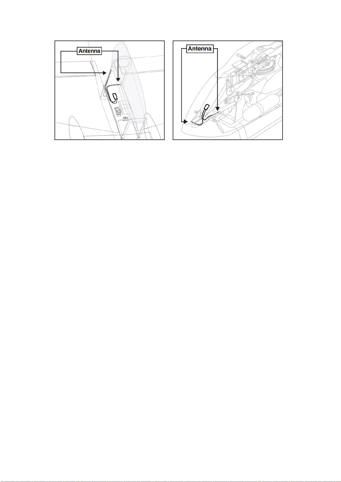
① Keep antennas as straight as possible and 90° as below, or the effective control range will
reduce.
② Big models may contain metal parts that influence signal emission. In this case, antennas should be
positioned at both sides of the model to ensure the best signal status in all circumstances.
Radiolink Electronic Ltd
www.radiolink.com
11
③ Antennas should be kept away from metal conductor and carbon fiber at least half inch
away and no over bending.
④ Keep antennas away from motor, ESC or other possible interference sources.
Note Receiver contains some electronic components of high-precision. Be careful to avoid strong
vibration and high temperature.
When all the above steps are complete, please turn off the transmitter and repower on to test if the
receiver is correctly connected with it.
2. Transmitter Antenna Installment
① The transmitter antenna is adjustable so please make sure that the antenna never points
directly at the model when flying as this may possibly decrease the receiver signal.
②
Keep the antenna perpendicular to the transmitter to optimize the receiver performance. It
also depends on how you hold the transmitter. But in most cases, adjusting the antenna with
perpendicular position to the transmitter surface will achieve the best result. Please adjust the
transmitter antenna according to the way you hold the transmitter.
③
Never grip the antenna when flying as this degrades effective control range.
1.3 RADIO BASIC SETTING
1.3.1 Basic setting of the transmitter
(1) Display language: can be selected the display language of the function name, etc. in each
function menu. The screen reads "LANGUAGE". Change this to the desired language.
(2) Stick Mode: The screen reads "STK-MODE". Change this to the correct mode. Note that this will
NOT change the throttle and elevator ratchets, etc. Those are mechanical changes that must be
done by a service center.
(3) RF Mode: the LED indicator will become solid green when RF Mode is active.
(4) Adjusting Display Contrast: To adjust the display contrast, from the home menu press and hold
the END BUTTON. Turn the DIAL while still holding the END BUTTON: clockwise to brighten and
counterclockwise to darken the display.
(5) User name setting: user name can be set by DIAL and PUSH with letters and numbers.
(6) Alarming voltage:
Transmitter: preset 8.6V, can be self-set
Receiver: preset 4.0V, can be self-set
Ext: preset 10.1V, can be self-set
1.3.2 Model type
Under basic menu, use CURSOR to select MODEL TYPE and enter by pressing PUSH. There are
6 different types included in the system, HELICOPTER, AEROBASIC, GLID(1A+1F), GLID(2A+1F),
GLID(2A+2F), and MULTIROTOR, after model type is selected, press and hold PUSH for 1 second,
when the word “are you sure to change” displayed, model type is changed.
Radiolink Electronic Ltd
www.radiolink.com
12
1.3.3 Binding
Each transmitter has an individually assigned, unique ID code. Receiver should bind to
transmitter before starting operation. Once binding is complete, the ID code will be stored in the
receiver and no further binding is necessary unless the receiver is used with another transmitter.
When you purchase a new R12DS, this procedure is necessary; otherwise, the receiver will not
work.
1. Put the transmitter and the receiver close to each other within 50 centimeters.
2. Power on AT10II and receiver R12DS. The RED LED will be on.
3. Turn on AT10II and it will automatically bind to the closest receiver.
4. There is a black binding button (ID SET) on the side of receiver. Press the button for more than
1 second and release, the RED (by default, could be Purple for SBUS&PWM signal output) LED will
flash, meaning binding process is ongoing.
5. When the LED stops flashing and is always on, binding is complete.
Make sure servos connected with the receiver can be operated by the transmitter.
Note
AT10II is default 12 channels and can be changed to 10 channels. In order to bind to
non-12-channel receivers (R6DS, R6DSM, R9DS), channel quantity needs to change to 10
channels.
How to setup the channel quantity of the transmitter: power on AT10II--Long press MODE to enter
BASIC MENU-- Toggle the CURSOR to select and enter SYSTEM --change CH-SELECT from
12CH to 10CH.
Since RadioLink radio control systems are not open source, that RadioLink transmitters are
ONLY compatible with RadioLink receivers.
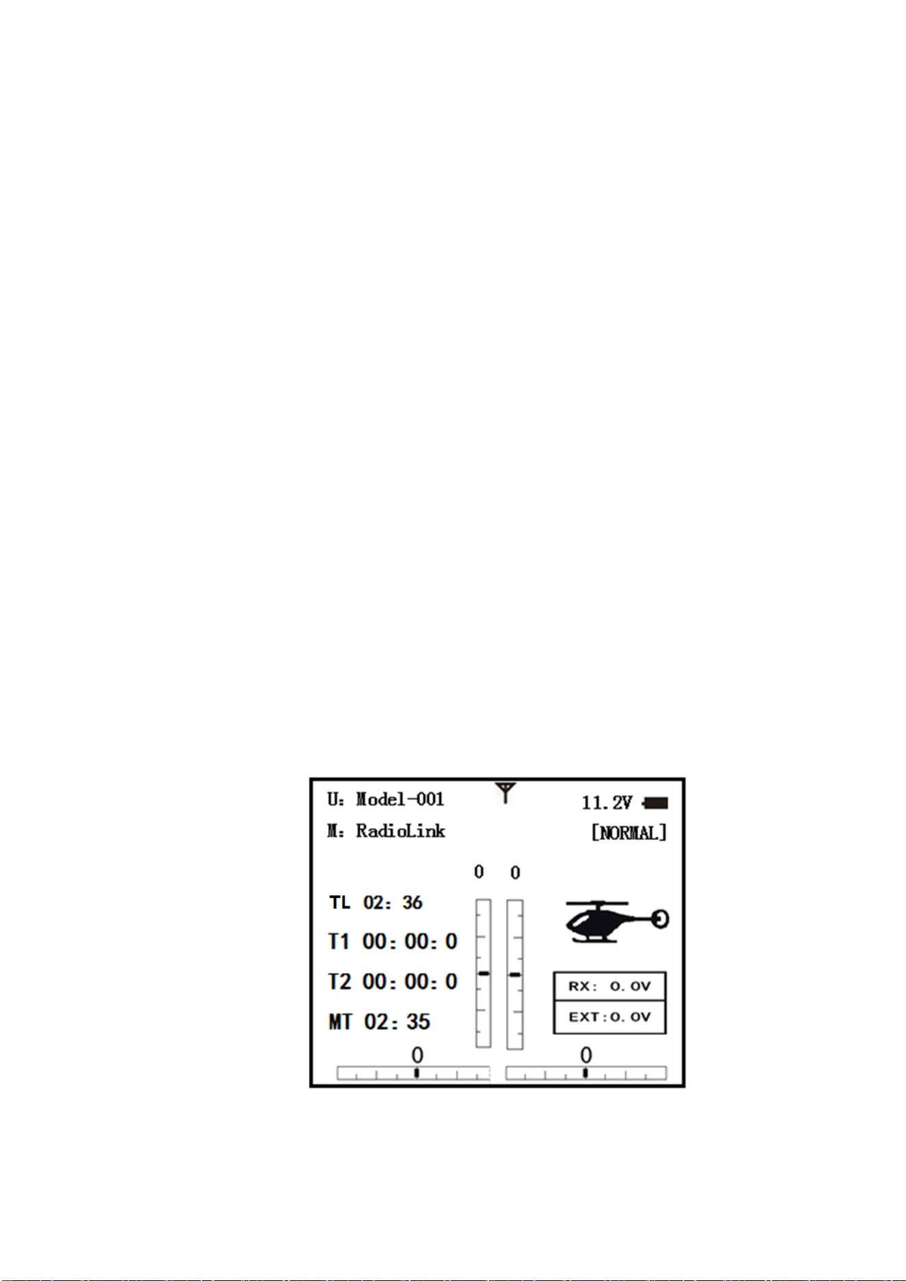
1.3.4 Transmitter Displays & Buttons
When you first turn on your transmitter, a confirmation double beep sounds, and the screen
shown below appears. Before flying, or even starting the engine, be sure that the model type and
name appearing on the display matches the model that you are about to fly! If you are in the wrong
model memory, servos may be reversed, and travels and trims will be wrong, leading to an
immediate crash.
Startup screen
TL: Shows the cumulated-ON times. (Hours: minutes)
T1/T2:T1/T2 timer display. (Minutes: seconds)
MT:Model timer display Shows the cumulated-ON time for each model. (Hours: minutes)
Button instruction

Radiolink Electronic Ltd
www.radiolink.com
13
MODE BUTTON:
Press and hold MODE BUTTON for one second to open programming menus. Press MODE
BUTTON to switch between BASIC and ADVANCE. Press MODE BUTTON to scroll between
conditions in certain functions.
END BUTTON:
Press END BUTTON to return to previous screen. Closes functions back to menus, closes menus
to start-up screen.
PUSH BUTTON:
Press PUSH BUTTON to select a function.
Turn DIAL:
Turn DIAL clockwise or counterclockwise to scroll through choices within an option of a function
Warning and error display
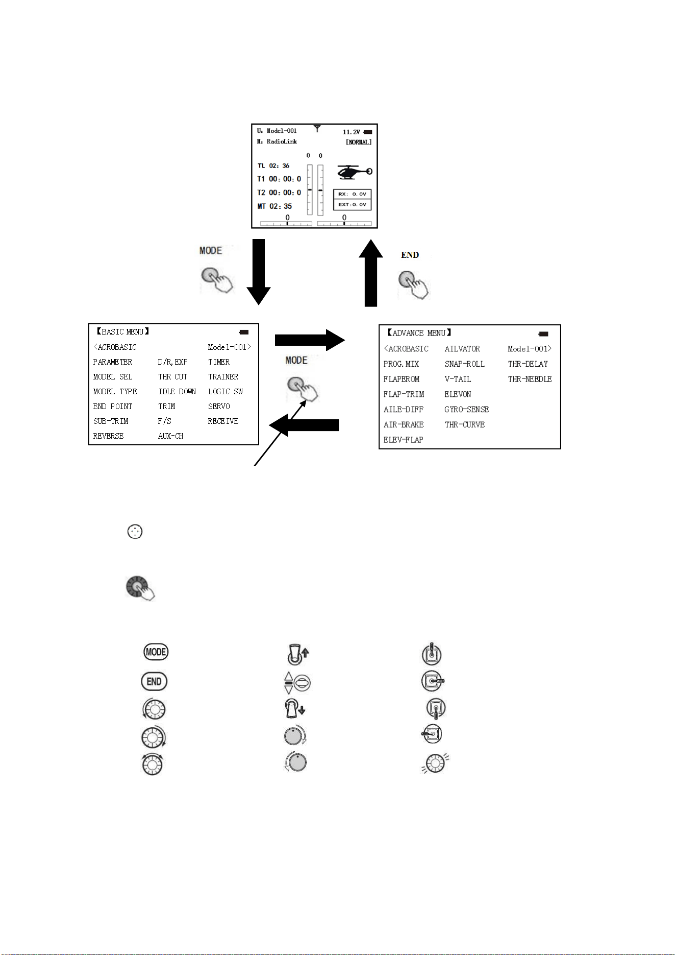
When the transmitter is powered on, warning or error may happen by the following probability:
1. Battery low voltage alarming
Lithium battery 2S-4S can fit for the transmitter, warning voltage can be self-set according to
different battery.
Setting step: power on the transmitter, press and hold MODE one second to enter basic menu,
and press PUSH to enter PARAMETER. Choose TX ALARM by DIAL and PUSH to change relative
data. Suggested min voltage is not less than 7.4V.
When the transmitter voltage is less than the setting voltage, it will beep till the transmitter is
powered off. Most important thing is to land your model plane when the transmitter alarms.
2. Mixing alarm
When the transmitter alarms mixing, it means at least one mixed switch is active. And when it is
inactive, warning will stop then. When the transmitter is powered on, in different model type, mixing
switch is shown as below:
ACRO: throttle cut, idle down, snap roll, air brake
GLID: butterfly, condition
HELI: throttle cut, throttle lock, speed up
If the warning continues even the related switch is set OFF, probably it is because some programs
mixed by one switch and status OFF reversed. Now you need to set mixing alarm again by DIAL.
PART 2. BASIC FUNCTION OF AIRPLANE
Please pay attention that the (BASIC) menu is suitable for all type models (airplane, helicopter,
glider, multicopter). The motor cut will be introduced in Glider (Basic) Menu, except Idle down
&Throttle cut. Helicopter Basic Menu include some extra function (swash plate tilting, throttle and
pitch curves and the tail rotor anti torque mixing under normal flight model) will be discussed in
Helicopter section.
******WARNING!!!******
TX LOW POWER!
Radiolink Electronic Ltd
www.radiolink.com
14
2.1 A QUICK GUIDE OF ACRO BASIC MENU
Mode Select
Switch Up
Stick Up
End Selection
Switch at Center
Stick Right
Dail Left
Switch Down
Stick Down
Dail Right
Turn Knob Right
Stick Left
Dail Right or Left
Turn Knob Left
Press Push Button
2.2 A QUICK GUIDE: GETTING STARTED WITH A BASIC 4-CHANNEL AIRPLANE
This guide is intended to help you acquainted with the radio, to give you some ideas and
direction on how to do. We give you a big picture overview of what we accomplish; a ‘by name’
description of what we’re doing to help you with the radio; then a step-by-step instruction to leave
out the mystery when setting up your model.
For additional details on each function, see that function’s section in this manual.
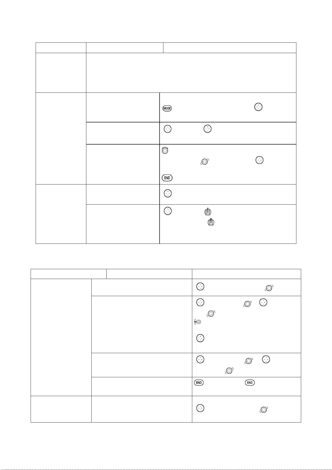
Startup screen
BASIC MENU
ADVANCE MENU
Press MODE BUTTON
for more than one
second to enter BASIC
MENU
Press MODE BUTTON to
switch between BASIC and
ADVANCE MENU
Press END BUTTON to
return to Start up screen
Turn CURSOR KEY to scroll through choices within an option
of a function.
Press PUSH BUTTON to select a function.
Radiolink Electronic Ltd
www.radiolink.com
15
Goals of Example
Steps
Input for Example
Prepare your
airplane
Install all servos, switched, receivers, etc. per your model’s instructions. Turn on
transmitter then receiver; adjust all linkages so surfaces are nearly centered.
Mechanically adjust all linkages as close as possible to proper control throws.
Check servo direction. Make notes now of what you will need to change during
programming
.
Name the model
(Note that you do
not need to do
anything to ‘save’
or store this data).
Open the Basic menu, then
open the PARAMETER
T
urn on the transmitter.
for 1second to basic menu. to choose
model
Go to Model Name
to Mode, to Mode name,press PUSH to
setting
Input airplane’s name
Close the Model submenu
To change first character, when proper character is
displayed, push to select.To move to next
character. Repeat as needed.
return to BASIC menu
Need to adjust EN
D-POINT to meet
with the related ser
vo.
In the BASIC menu find the
END POINT
to END POINT,press PUSH BUTTON to set
Adjust end point (EX:
THRO servo) Close the
function
to Throttle Throttle stick until carburetor
closes as desired. until throttle arm just open
carburetor at fully throttle stick. Repeat for each
channel as needed.
With digital trims you don’t shut the engine off with THROTTLE TRIM. Let’s set up IDLE-DOWN and ‘throttle
cut’
Goals of Example
Steps
Input for Example
Idle down setting: Idle
down is to lower the en
gine speed for landing,
snap rolling acrobatic
display, and launching
etc. It is preset OFF an
d mainly used to start e
ngine and glide, then t
o avoid flameout.
From the BASIC menu choose IDLE
DOWN.
to IDLE DOWN,press
Activate and adjust IDLE DOWN
to MIX,press , to ON,
press
C to center position, screen now reads
ON.
to RATE, to increase rate until engine
idles reliably but low enough to sit still.
Optional: change switch C command
to POSI,press , as you
desired press
Close the function
BASIC menu, again to startup
screen.
THR CUT shuts the
engine off completely
with the flip of a
From BASIC menu, choose THR CUT
to THR CUT,press
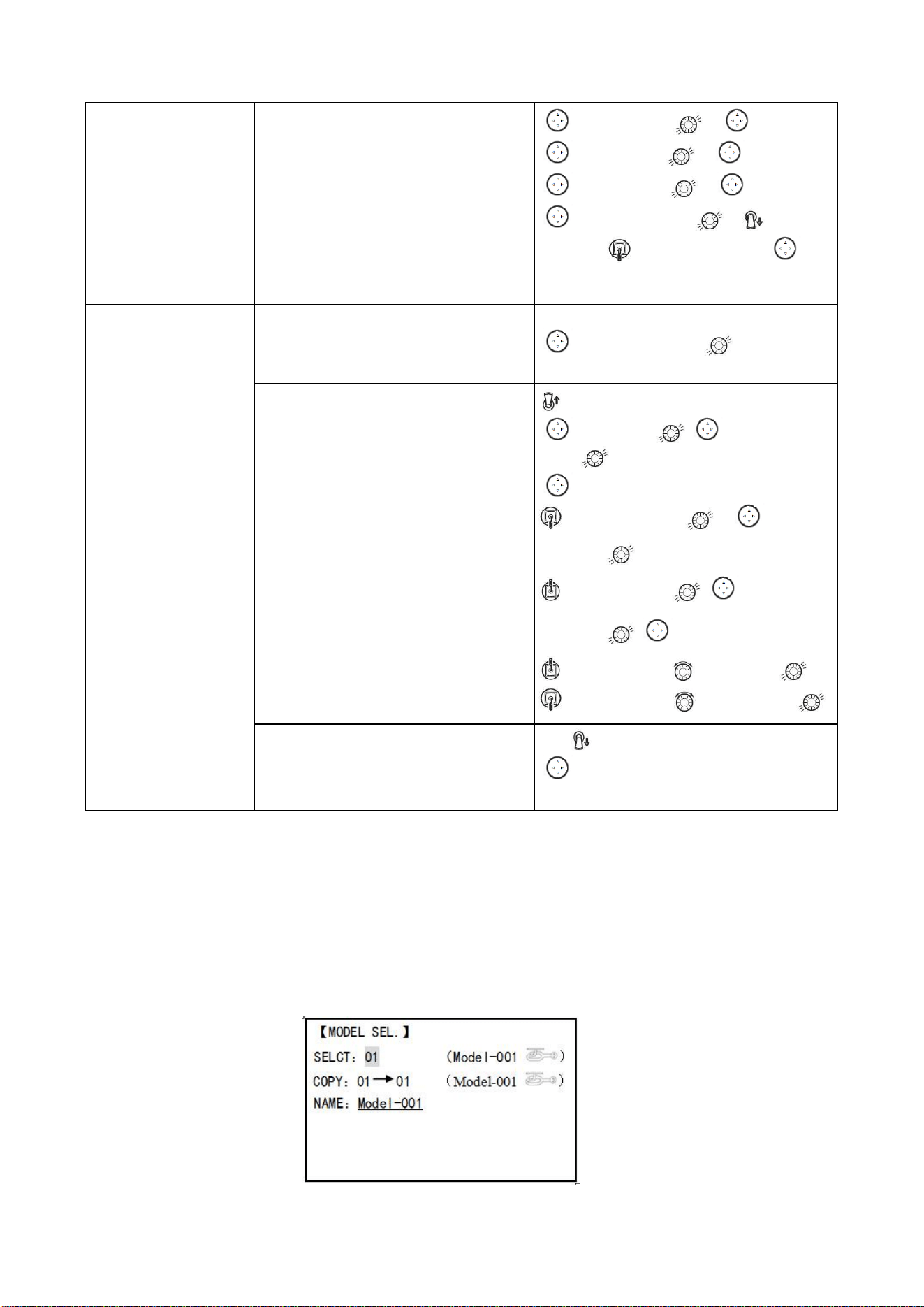
Radiolink Electronic Ltd
www.radiolink.com
16
switch.(Note: Do Not
assign IDLE DOWN and
THR CUT to both
position of a 2 position
switch
Activate, assign SWITCH and adjust.
Close the function
to MIX,press , to INH
to SW,press , to SwC
to POSI, press , to DOWN
to RATE,press , to down
position, throttle stick down until
the throttle barrel closed
Set up dual/triple rates
and exponential
(D/P,EXP) (Note that in
the middle of the left
side of the screen is the
name of the channel and
the switch position you
are adjusting. D/R may
be set per channel by
choosing the desired
switch and mix rate.
From BASIC menu, choose the
D/R,EXP
to D/R,EXP,press
Choose the desired control, and set the
first (EX: high) rate throws and
exponential.
SwA to up position A
to CH, press , to choose CH2,
press
to D/R
Stick down,press , to
set ,press
Stick up,press , to
set ,press , to EXP
Stick up, press to set,press
Stick up, press to set,press
Set the second(low)rate throws and
exponential.
SwA to down position
to D/R
Repeat steps above to set low rate.
2.3 AIRPLANE BASIC FUNCTION
2.3.1 Model Select
Model submenu: includes three function that manage model memory: MODEL
SELECT,MODELCOPY and MODEL NAME. Since these functions are related, and all basic
features are used with most models, they are together in the Model submenu.
MODEL SELECT
Totally there are 15 models stored in the system, followed by model name and plane type to use
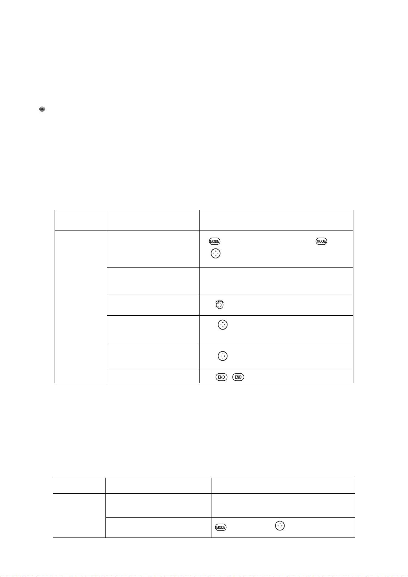
Radiolink Electronic Ltd
www.radiolink.com
17
on tap, thus you don’t need to set every time for different plane. MODEL NAME, MODEL TYPE and
transmitter voltage. Make sure that MODEL TYPE is accomplished with your plane type before flight.
Or it will cause error in servo and rudder.
COPY
Save the present data as another model type, it will be displayed by shadow area to differ from.
When this copy start, the object data will be fully covered including name, type and module type,
and cannot recover.
Caution: when you save the present model type as another, all related data will be copied
including the original model name. Accordingly, if you want to change the model type, the whole
data need to reset, also for model name. The first thing to copy is to change the model type or
delete the original name and rename a new model to avoid confusion.
Model Name
This is used to set the present model name. Name all model to identify each other, and fast
select the model type and reduce possible crash by wrong model type using.
Format to name a model:
•the name can be more than 9 characters
•every character can be letter, number, blank or special characters
•factory setting name MODEL-XXXX will be shown as (example model 1 display MODEL-0001)
Goals
Steps
Inputs
Name
model3
“Cap-232_”
(where
underline
represents a
blank space
Open Model
for 1second.(If ADVANCE, again)
to MODEL SEL. Press PUSH
Confirm correct model
(Ex:3)
If select doesn’t show ‘3’,perform Model
select
Go to Name to change the
first character(Ex: M to C)
M to C, press PUSH.
Change the next character
to choose character, press PUSH to
confirm
Repeat the prior steps until
finish naming model.
to a Repeat.
Close
Sub-menu select: All parameters need one time setting. After the model type selected, you need to
set the related data for it.
•what is the model type
•whether the throttle channel 3 is right for the selected model type? Or you need to make sure
channel 3 is of full range adjustable (glider only). Also to different model, you can set by throttle
reverse correspondingly.
Initialize the original data first, and set new data for the selected model type
Model reset: model reset is available in factory only. If you want to delete a new set model type,
you need to delete one by one.
Goals
Steps
Inputs
Reset model
memory 1
Confirm you’re currently using
the proper model memory(Ex:1)
On home screen, check model name and No.
on top left, if not correct use Model Select.
Open PARAMETER submenu
For 1second to Model SEL, Push.
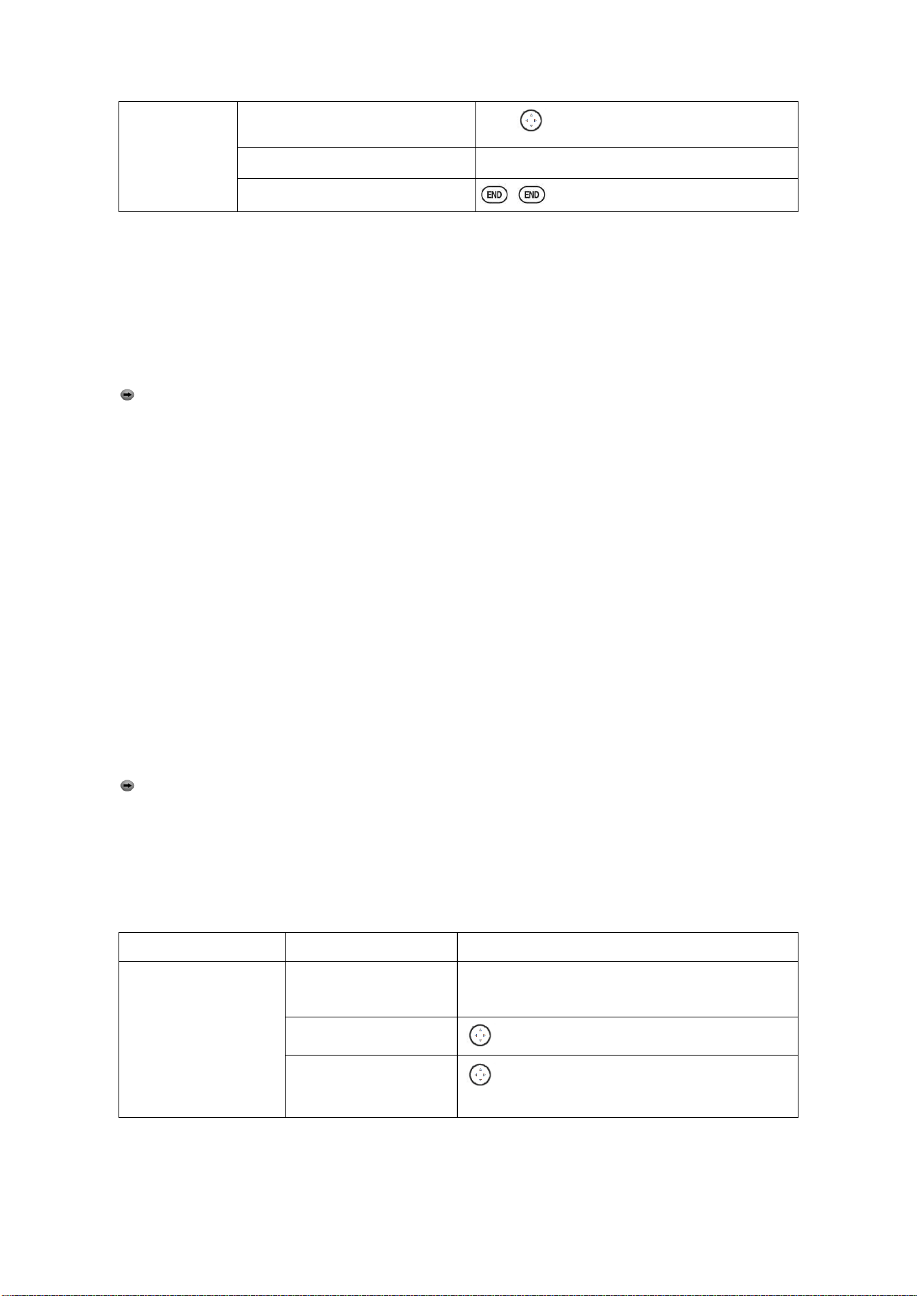
Radiolink Electronic Ltd
www.radiolink.com
18
Reset the memory
Push to Model 1, PUSH
Confirm the change
Are you sure? Press PUSH
Close
Model type select
•ACRO basic:
Drive ACRO basic type (multi airfoil. Detail in Twin Aileron Servos, Twin Elevator Servos,
ELEV-FLAP mix and V-tail)
•glider:
Different tail type (detail in glider type)
•helicopter:
8 swash plate types (detail in helicopter type)
Caution: decide a model type for the model plane. To most fixed wing plane, aero basic is
better, because it has some function glider doesn’t have. While sometimes, glider (2A+1F) is better.
•functions specially for aero basic:
•snap roll
•ELEV-flap mix (twin Elevator Servos support)
•oil power plane: idle down、throttle shut、throttle needle mix etc.
•functions aero basic doesn’t have:
5 individual flight conditions (normal, start, speed, distance, landing)
If the model type selected for glider or helicopter, please go to the related chapter for setting.
After model type changed, all parameters need to reset, including name.
2.3.2 Model Type
Data reset
All set data can be reset to factory setting. This function will not delete all model type set in the
radio.
Setup step:
Enter the basic menu for MODEL TYPE, use dial to choose a proper type and press PUSH for
one second, when the screen displays “are you sure”, press PUSH and the radio will beep,
and it is set to factory data.
Caution: don’t power the radio off before setting is finished, or the setting is invalid.
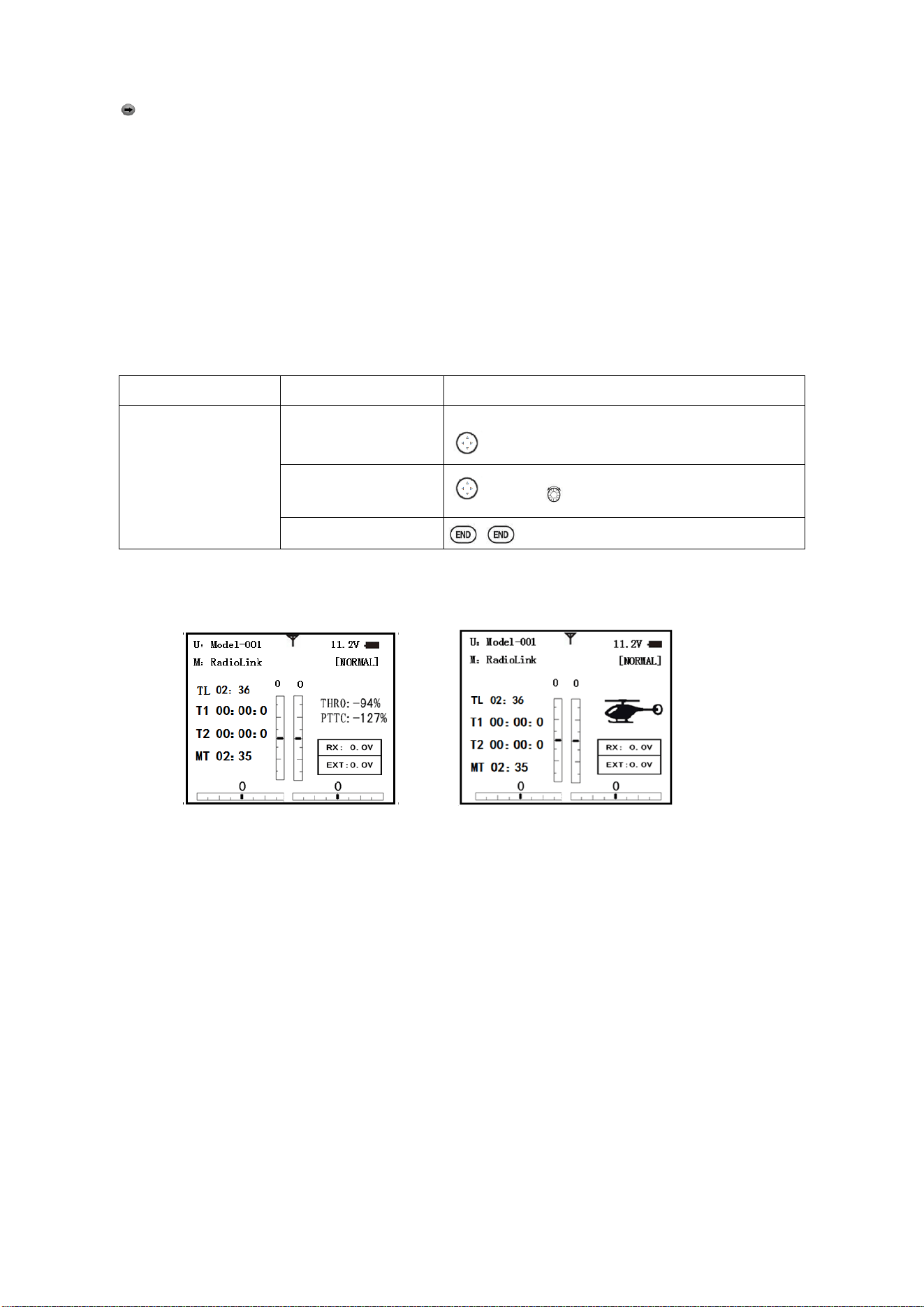
Model Select
Goals
Steps
Inputs
Select proper Model
Type for your mode
l(Ex: ACRO)
Open BASIC menu, then
PARAMETER submenu
Turn on the transmitter. MODE for 1s.(If
ADVANCE, Mode again.
Go to MODEL TYPE.
to Mode TYPE, press PUSH.
Select proper type Ex:
ACRO Confirm the
change. Close.
to ACRBASIC,PUSH for 1s. “Are you sure”
display. PUSH to confirm. End to BASIC menu.
Second aileron :( AILE-2) (ACROGLID1A+1FGLID2A+1F only): change the default choice for dual
aileron servos from channels 6(FLAPERON) to channels 5 and 6, or channel 3 and 6, or channel
7(AIL-DIF) to channels 5 and 7. This allows you to utilize these 2 great functions while utilizing
5-channel receiver.
Radiolink Electronic Ltd
www.radiolink.com
19
Caution: Changing AILE-2 only tells the system which servos to utilize if FLAPERON or AIL-DIF
is activated. You still must activate that function and complete its setup for details on twin aileron
servos, including using AILE-2.
(Only for glider 1A+1F) if the channel 3 is set as the second aileron, the receiver F/S will become
invalid.
Adjustable travel limit (ATL)
Make the channel 3 TRIM LEVER (THROTTLE TRIM) effective only at low throttle, and disabling
the trim at high throttle. This prevents pushrod jamming due to idling trim changes. This function
defaults to ON. If you are not using channel 3 for throttle, you may want trim operation the same as on
all other channels. To do so, set ATL to OFF. If you need the ATL to be effective at the top of the stick
instead of the bottom, reverse the THR-REV setting. Note that this affects all models in the radio, not
just the model you are currently editing.
Goals
Steps
Inputs
Change ATL from ON
to OFF for battling
robots, tanks,
airbrakes and other
channel 3 uses.
Open Basic menu,
then to Mode Type.
Mode for 1s (If ADVANCE, Mode again).
To Mode TYPE, press PUSH.
Go to ATL and
change. (Ex: to OFF)
to ATL, to OFF.
Close
Home screen display
As shown below, home screen will display plane type and throttle pitch:
ILLUST: displays the illustration of helicopter in the home screen. (Default)
THR/PIT: displays the current throttle and pitch position in the home screen.
Step to change plane type image to THR/PIT: under model type helicopter, enter basic menu,
choose MODEL TYPE, and enter HOME DISP, press PUSH, then DIAL to THR/PIT, then press
PUSH.
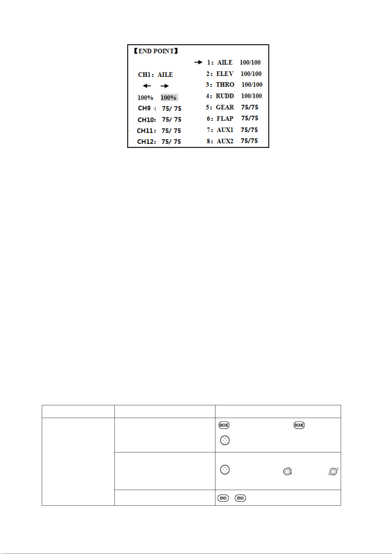
2.3.3 End Point of servo travel adjustment (END POINT, also called EPA)
The most flexible version of travel adjustment is available. It independently adjusts each end of
each individual servo’s travel, rather than one setting for the servo affecting both directions. Again, for
CCPM helicopters, be sure to see SWASH AFR prior to adjusting end points.
Radiolink Electronic Ltd
www.radiolink.com
20
Adjustability:
• Can set each direction independently.
• Ranges from 0% (no servo movement at all) to 140%. At a 100% setting, the
Throw of the servo is approximately 40°for channels 1-4 and approximately 55°for channels 5-8.
• Reducing the percentage settings reduces the total servo throw in that direction.
Examples:
• Adjust the throttle high end to avoid binding at the carburetor, and low end to allow for proper
carburetor closure.
• END POINT may be adjusted to 0 to keep a servo from moving one direction, such as flaps not
intended to also operate as spoilers.
• Retract servos are not proportional. Changing END POINT will not adjust the servo.
END POINT adjusts only the individual servo. It will have no effect on any other servo that is operated
in conjunction with this servo via mix or preset programming such as FLAPERON, AILEVATOR, etc.
This is so that each individual servo can be carefully fine-turn to avoid binding and other conflicts. To
adjust the total travel of a function such as FLAPERON, make the adjustments in that function's
controls. For CCPM helicopters, adjust the total travel of the function, such as collective pitch, in
SWASH AFR. Adjust the linkage or the END POINT? It is nearly always best to adjust your linkages
to get as close as possible prior to utilizing END POINT. The higher the END POINT setting, the better
position accuracy and the more servo power available at nearly any position (except if using digital
servos). Higher END POINT values also mean longer travel time to reach the desired position, as you
are utilizing more of the servo's total travel. (For example, using 50% END POINT would give you
only half the steps of servo travel, meaning every click of trim has twice the effect and the servo gets
there in half the time). End point (and moving the linkage) = torque, accuracy, but transit time to get
there.
• END POINT (instead of adjusting linkages) = travel time, but torque, accuracy.
Engine idle management: IDLE-DOWN and THR-CUT: functions which work with the digital
THROTTLE TRIM to provide a simple, consistent means of engine operation. No more fussing with
getting trim in just the right spot for landings or take offs! For additional engine adjustments, see
THROTTLE-NEEDLE and THROTTLE DELAY.
Goals
Steps
Inputs
Decrease the flap servo
throw in the upward
direction to 5% to allow
trimming of level flight
only and down travel to
85% to prevent binding.
Open END POINT function
for 1s.(If ADVANCE, again)
to END POINT,PUSH
Choose proper channel and move
stick or Knob in direction you
want to adjust and set servo throw
(Ex: flap up 5%)
to FLAP,PUSH, to 5%,press
Close
2.3.4 Trim
Radiolink Electronic Ltd
www.radiolink.com
21
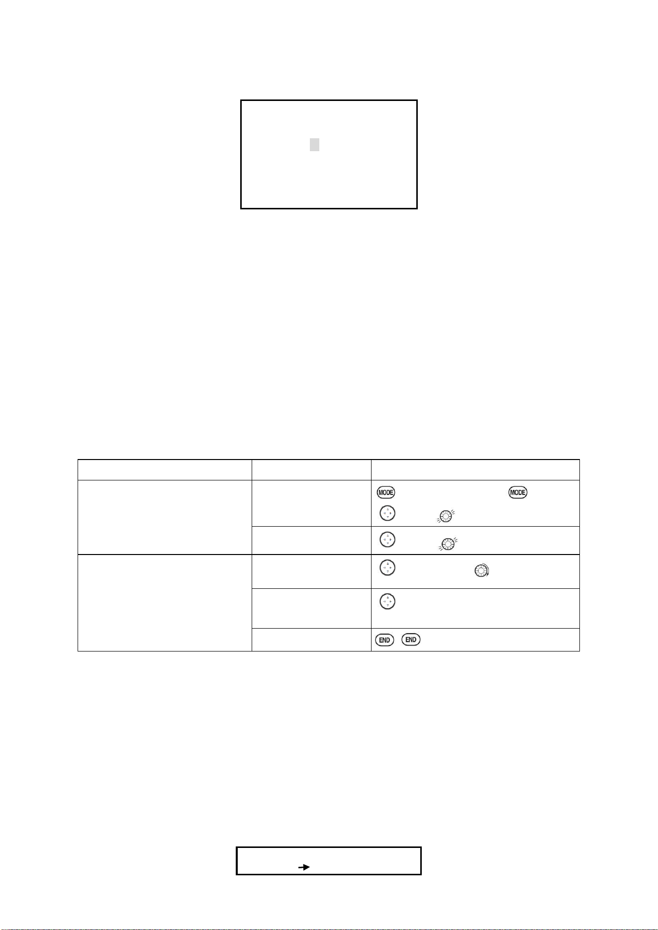
TRIM submenu: resets and adjust effectiveness of digital trims.
【TRIM】
RESET:Execute
STEP-AILE: 4( 0)
ELEV: 4( 0)
THRO: 4( 0)
RUDD: 4( 0)
The AT10II has digital trims which are different from conventional mechanical trim sliders. Each
TRIM LEVER is actually a two-direction switch. Each time the TRIM LEVER is pressed, the trim is
changed a selected amount. When you hold the TRIM LEVER, the trim speed will increase. The
current trim position is graphically displayed on the start up screen. The TRIM submenu includes
two functions that are used to manage the trim options.
(1) Trim reset (RESET): Electronically centers the trims to their default values. Note that the
SUB-TRIM settings and the trim STEP rate are not reset by this command.
(2) Trim step (STEP): changes the rate at which the trim moves when the TRIM LEVER is
activated. It may be set from 1 to 40 units, depending on the characteristics of the
MULTIROTOR. Most ordinary MULTIROTOR do well at about 2 to 10 units. Generally
larger trim steps are for models with large control throws or for first flights to ensure
sufficient trim to properly correct the model. Smaller trim steps are later used to allow
very fine adjustments in flight.
HELI models only: OFFSET is available in the idle ups. If OFFSET is inhibited, adjustment of the
TRIM LEVERS will adjust the trims for all flight conditions. If OFFSET is active, then moving the
trims within any one condition will affect only that condition.
Goals
Steps
Inputs
Reset trims to neutral after having
adjusted all linkage. Note: this is
one of the several functions for
which the radio requires
confirmation to make a change
Open BASIC menu,
then open TRIM
submenu.
For 1s. (If ADVANCE, again)
TRIM .
Confirm the reset.
to reset, for 1s. Beep sounds.
Double the sensitivity of the
AILERONTRIM LEVERS for a
first flight of an aerobatic model
to ensure sufficient range to trim
the model for level flight.
Adjust the size of
thestep (Ex:8)
to AILE, PUSH to 8,PUSH
Repeat for other
channel.
to ELEV,PUSH to new setting.
Repeat as needed.
Close
2.3.5 SUB TRIM
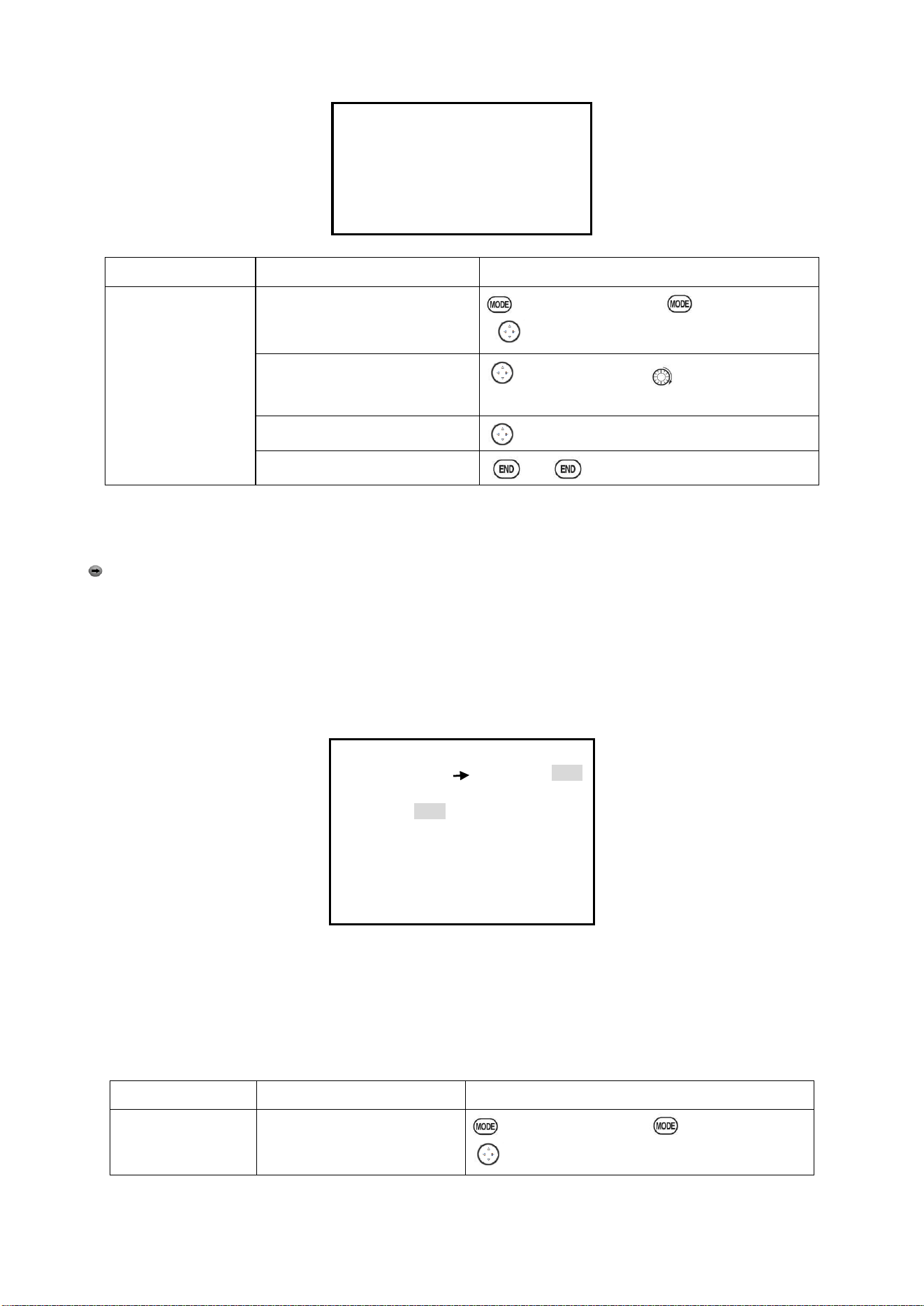
SUB-TRIM: makes small changes or corrections to the neutral position of each servo. Range is
-120 to +120, with 0 setting, the default, being no SUB-TRIM.
We recommend that you center the digital trims before making SUB-TRIM changes, and that you try
to keep all of the SUB-TRIM values as small as possible. Otherwise, when the SUB-TRIM is of large
values, the servo's range of travel is restricted on one side.
The recommended procedure is as follows:
• Measure and record the desired surface position;
• Zero out both the trims (TRIM RESET menu) and the SUB-TRIM (this menu);
• Mount servo arms and linkages so that the control surface’s neutral is as correct as possible; and
• use a small amount of SUB-TRIM to make fine corrections.
【SUB-TRIM】
1:AILE
0
Radiolink Electronic Ltd
www.radiolink.com
22
CH1:
AILE
2:ELEV
0
0
3:THRO
0
4:RUDD
0
CH9:
0
5:GEAR
0
CH10:
0
6:FLAP
0
CH11:
0
7:AUX1
0
CH12:
0
8:AUX2
0
Goals
Steps
Inputs
Adjust the flap
servo’s SUB TRIM
until its center
exactly matches the
aileron servo’s center
as they work together
as FLAPERON.
Open BASIC menu, then open
SUBTRIM
for 1s .(If ADVANCE again)
to SUB-TRIM
Choose the channel to adjust
until surfaces match(Ex: flap)
to FLAP,PUSH, as needed to each
channel.
Repeat for other channels
as needed.
Close
2.3.6 Servo Reversing (REVERSE):
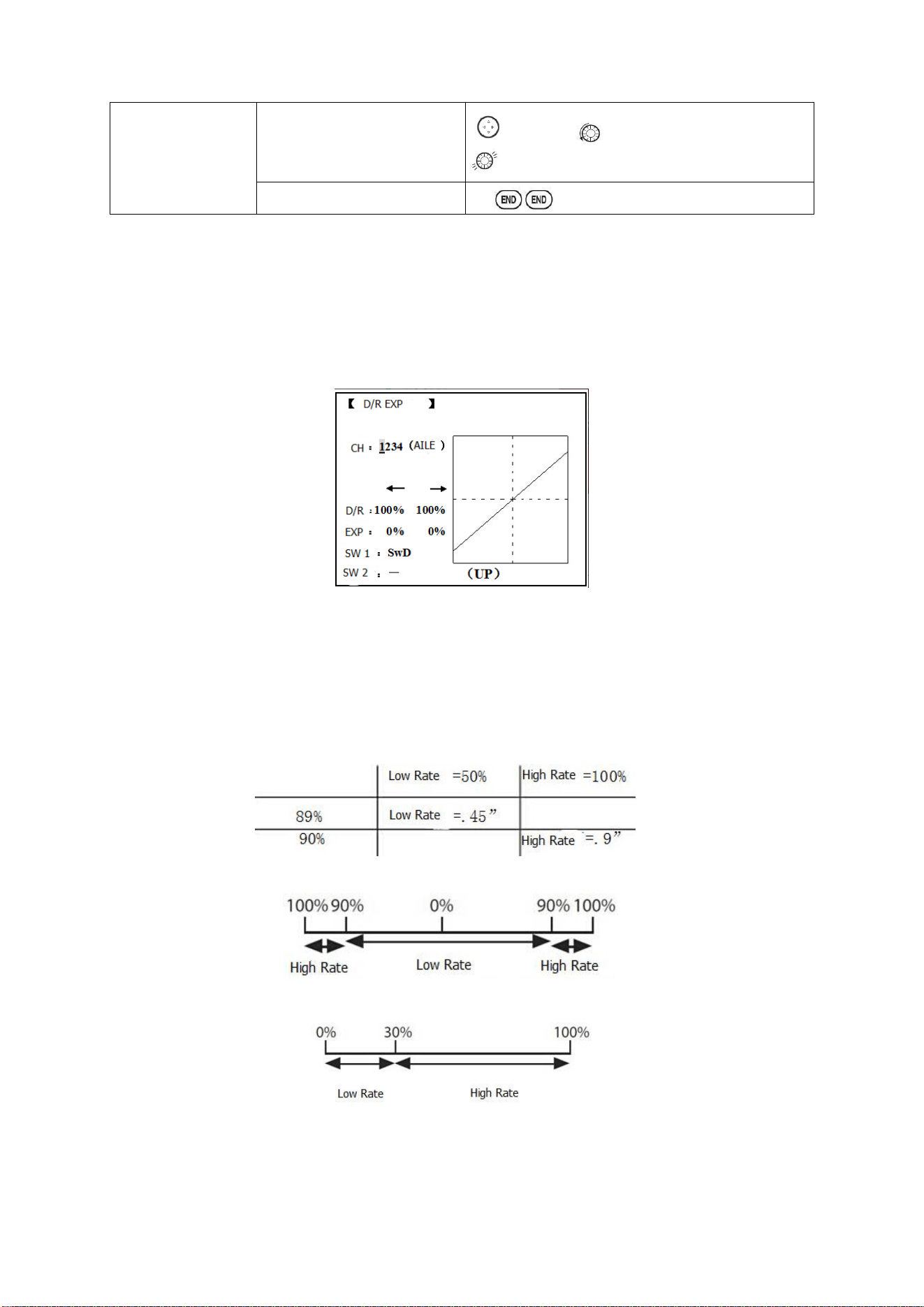
Changes the direction an individual servo responds to a CONTROL STICK motion.
Since channel 9 and 10 are switch only, its servo REVERSE is in the AUX-CH control screen
with its switch assignment. Be sure to read the section on SWASH AFR before reversing any
servos.
Except with CCPM helicopters, always complete your servo reversing prior to any other
programming. If you use pre-built ACRO/ GLID functions that control multiple servos, such as
FLAPERON or V-TAIL, it may be confusing to tell whether the servo needs to be reversed or a
setting in the function needs to be reversed. See the instructions for each specialized function for
further details.
【REVERSE】
1:AILE
NOR
CH1:
AILE
2:ELEV
NOR
REV
NOR
3:THRO
NOR
4:RUDD
NOR
CH9:
NOR
5:GEAR
NOR
CH10:
NOR
6:FLAP
NOR
CH11:
NOR
7:AUX1
NOR
CH12:
NOR
8:AUX2
NOR
Always check servo direction prior to every flight as an additional precaution to confirm proper
model memory, hook ups, and radio functions.
Servo reversing
Goals
Steps
Inputs
Revere the direction
of the elevator servo.
Open REVERSE function
for 1s .(If ADVANCE again)
to REVERSE, PUSH.
Radiolink Electronic Ltd
www.radiolink.com
23
Choose proper channel and
set direction(Ex: ELEV
REV)]
to ELEV,
to REV,’Are you sure? displays
for 1s。
Close
2.3.7 Dual/triple rates and exponential (D/R,EXP)
Dual/Triple Rates: reduce/increase the servo travel by flipping a switch, or (ACROGLID) they can
be engaged by any stick position. Dual rates affect the control listed, such as aileron, not just a
single (ex: channel 1) servo. For example, adjusting aileron dual rate will affect both aileron servos
when using FLAPERON or AIL-DIF, and both aileron and elevator servos’ travel when using
AILEVATOR or ELEVON or a CCPM helicopter.
Activation:
• Any SWITCH, A-H. If you choose a 3-position switch, then that dual rate instantly becomes a triple
rate.
• The glider programming offers you the choice of Condition. This option allows you to have a
separate rate for each of condition. (GLID)
• Stick position (ACRO GLID). (Ex: On rudder you normally use only the center 3/4 of the stick
movement except for extreme maneuvers such as snaps/spins/stalls. As long as your RUDDER
STICK does not exceed 90% (ie. stall turn), the rudder goes to high rate's 90%, which is a MUCH
higher amount of travel than your low rate at 89%)
Adjustability:
• Range: 0 - 140% (0 setting would deactivate the control completely.) Initial value=100%
• Adjustable for each direction (ACRO/ GLID)
(i.e. Up/down, left/right) (Ex: Most models fly upright without any elevator trim, but require some
down elevator when inverted just to maintain level flight. By increasing the down travel by the
amount required to hold the model inverted, the model now has equal travel available from level
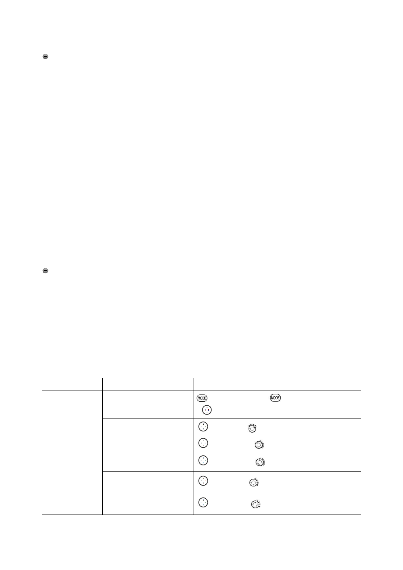
Radiolink Electronic Ltd
www.radiolink.com
24
upright or level inverted.
Only if any stick is chosen by the item of "SW1", a switch can also be chosen by the item of
"SW2." When operated simultaneously, the switch operation has priority over the stick operation.
(ACRO)
Exponential:
Change the response curve of the servos relative to the stick position to make fly more pleasant.
You can make the servo movement less or more sensitive around neutral for rudder, aileron,
elevator, and throttle (except HELI type use THROTTLE CURVE instead). (ACRO type throttle EXP
and THROTTLE CURVE can not be activated simultaneously). Many models require a large
amount of travel to perform their best tricks.
However, without exponential, they are touchy around neutral, making them unpleasant to fly and
making small corrections very difficult. Additionally, by setting different exponentials for each rate,
you can make the effectiveness of small corrections similar in each rate, as in our example below:
The best way to understand exponential is to try it:
• Having made no changes yet in the D/R, EXP screen, move SWITCH D to DOWN (toward the
AILERON STICK).
• Move SWITCH D up. Hold the AILERON STICK at 1/4 sticks and moves SWITCH D down.
• Notice how much less travel there is.
• Go to 3/4 stick and repeat. Notice how the travel is much closer, if not identical.
Adjustability:
• More sensitive around neutral. (Positive exponential)
• Less sensitive around neutral. (Negative exponential)
• Adjustable for each direction. (ACRO/GLID)
For throttle, exponential is applied at the low end to help nitro and gasoline engines have a linear
throttle response, so that each 1/4 stick increases engine RPM 25% of the available range. (In most
engines this ranges from 5-60%)
Special note for helicopters: Helicopter model types have just a single rate for each switch
position rather than a rate for each side of the servo's travel per switch position. Additionally, setting
the D/R, EXP for each switch position requires cursor back to the No. setting and changing the
switch position here. Just flipping the switch does not affect the screen setting, allowing dual rates
to be assigned with idle-up and other features on certain switches, and does not require putting the
model in that condition to make modifications.
Special note for conditions: The helicopter and glider programming offers you the choice of
COND. This option allows you to have a separate rate for each of the 3 controls automatically
selected when changing conditions, for a total of FIVE rates available. Simply change the switch
choice to COND. and then:
(HELI) press the CURSOR LEVER to toggle through the 5 conditions while setting the rates.
(GLID) activate the corresponding condition to edit the rates.
Goals
Steps
Inputs
Set up dual rates
and exponential in
HELI model.
Open D/R,EXP
for 1s.(If ADVANCE again)
to D/R EXP,PUSH.
Choose channel
to CH, Push. to desired channel. PUSH
Choose first channel position
to NO,PUSH. to UP,PUSH.
Set rate and EXP(Ex: High
rate=95%,0%exponential)
to Rate, PUSH. to 95%,confirm 0% EXP.
Go to 2nd switch position and
set rate and exponential.
to NO,PUSH to DOWN,PUSH.
Optional: if using a 3 position
switch, set 3rd rate.
to NO,PUSH. to COND repeat above.
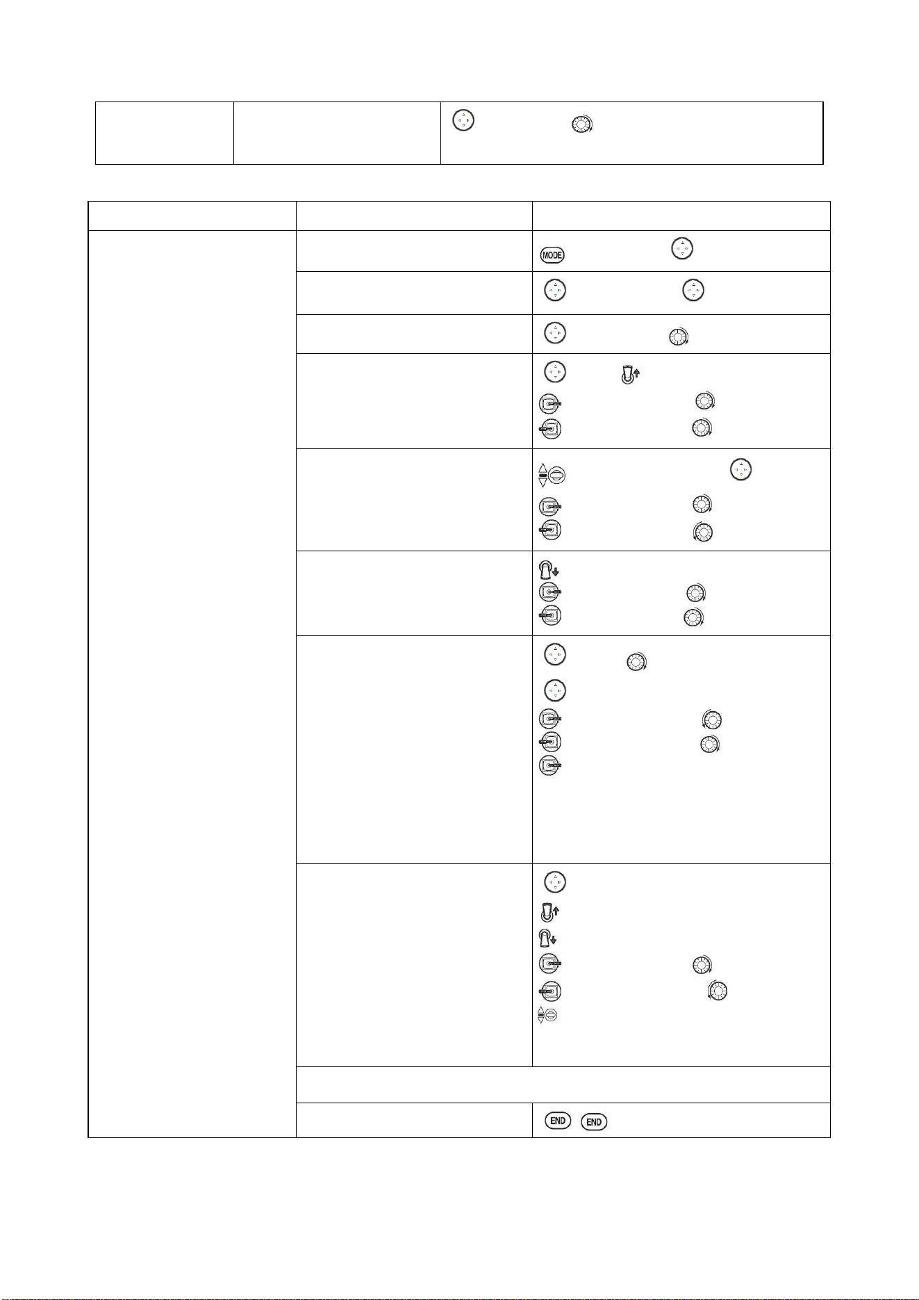
Radiolink Electronic Ltd
www.radiolink.com
25
Optional: assign dual rates to
have one for each condition.
to SW,PUSH. to COND.
Repeat steps above to adjust for each condition.
Goals
Steps
Inputs
Set up aileron triple rates on
SWITCH C with travel
settings of 75%(normal)
25%(slow roll)and 140%
(extreme aerobatics)and
exponential setting of
0%, +15%, and -40%
respectively.
NOTE: This normal rate has
no exponential so it has a
Very linear, normal feel.
This is slow roll rate has
positive exponential
(the opposite of what most
people normally uses),
which makes the servos
more responsive around
center. This makes the servos
feel the same around center
in the normal and low rates,
but still gives a very slow
roll rate at full stick.
3D rate (extreme aerobatics)
has a very high distance of
travel nearly twice that of the
normally rate.
Therefore, using a very high
rate negative exponential
setting softens how the servos
responses around center stick.
Open D/R,EXP
for 1s to BASIC( to D/R,EXP,PUSH.
Choose channel to change
(Ex:aileron is already selected)
to CH,PUSH, to AILE,PUSH
Optional: Change switch position.
to SW,PUSH to SWC,PUSH
Confirm switch is in desired
position and set rate.(Ex: up=high
rate,75%)
to D/R
C
to UP position.
AILERON STICK to75%.PUSH
AILERON STICK to75%.PUSH
Move Switch to 2nd rate position
and set this particular rate (Ex:
center=low rate,25%)
SWC
to center position, to D/R
AILERON STICK to 25%,PUSH
AILERON STICK to 25%,PUSH
Optional: If using a 3 position SW,
move SW to 3rd position and set
this rate.(Ex: DOWN=3D rate,
140%)
SWC to DOWN position.
AILERON STICK to 140%,PUSH
AILERON STICK to 140%,PUSH
Optional: except using a switch,
you can set high rates to be
triggered when the stick moves
past a certain point. To test this,
set aileron high rate to 25%.Now
set switch assignment to AIL
(90%). Move AILERON STICK to
the right and notice the huge jump
in travel after the stick moves 90%
of its distance.
to SWA to AILE(90%)
,
PUSH
to D/R
AILERON STICK
to 25%
AILERON STICK to 25%
AILERON STICK and watch screen
graph. See the change? You may also
change the trigger point by holding the stick
at the desired point then pressing and
holding the PUSH.
Set each rate’s EXP.
(Ex:0%,+15%,-40%)
to EXP .PUSH
C to UP position confirm EXP reads 0.
C to DOWN position.
AILERON STICK to+15% .PUSH
AILERON STICK to+15%.PUSH
C to center position
Repeat to set low rate EXP to -40%.
Repeat above steps for elevator and rudder.
Close
2.3.8 Throttle Cut
AEROBASIC
Throttle cut (THR-CUT) (ACRO0/HELI): provides an easy way to stop the engine by flipping a
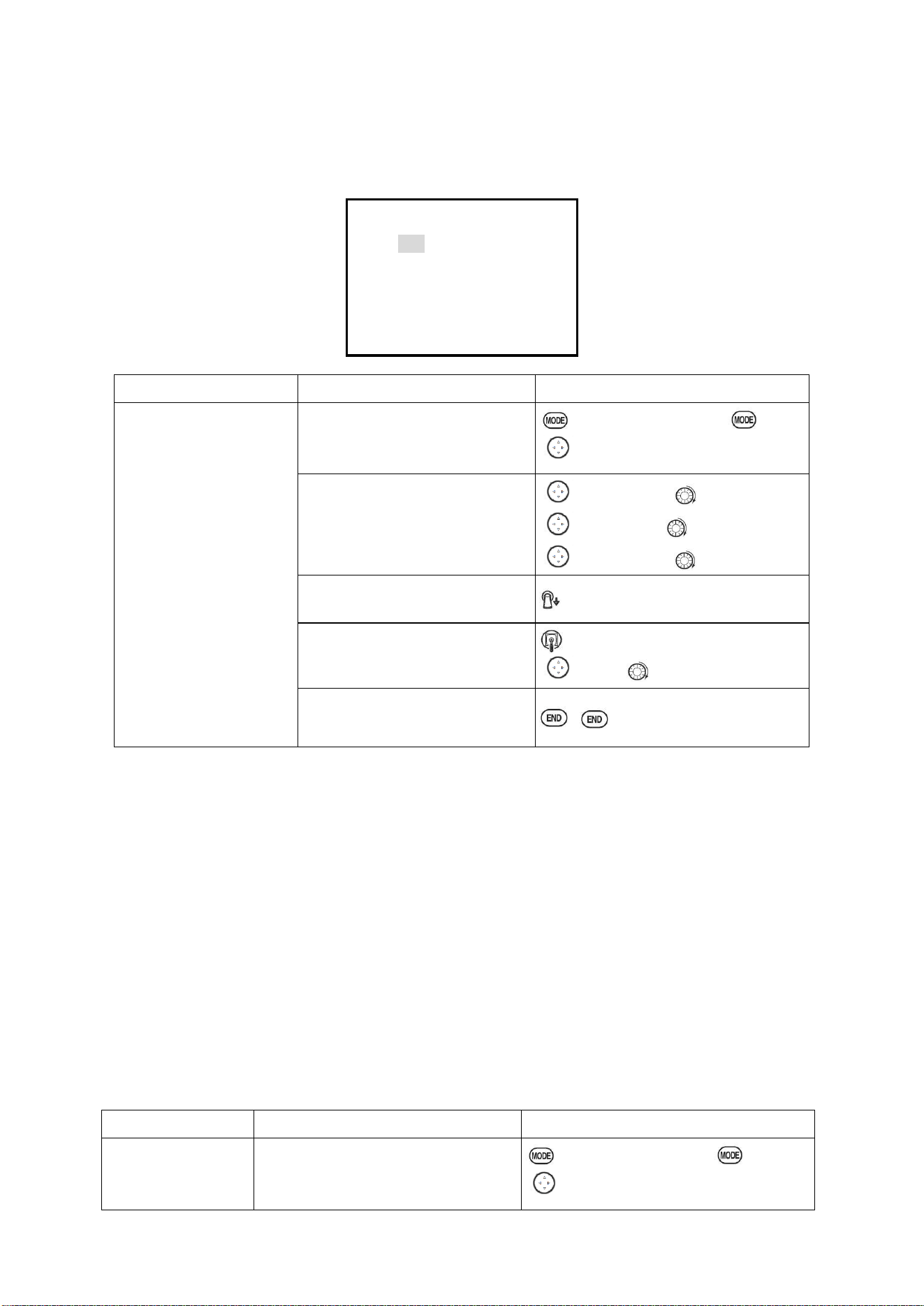
Radiolink Electronic Ltd
www.radiolink.com
26
switch (with THROTTLE STICK at idle). The movement is largest at idle and disappears at high
throttle to avoid accidental dead sticks. In HELI, there is an additional setting.
The switch's location and direction must be chosen. It defaults to NULL to avoid accidentally
assigning it to a switch, which might result in an unintentional dead stick in flight.
【THR CUT】
MIX:INH
RATE: 0%
THR:5%(100%)
SW:SwH
POST:DOWN
Goals
Steps
Inputs
Decrease the throttle
setting (at idle) to stop the
engine with the flip of a
switch.(NOTE that you
MUST assign a switch.
The default is NULL. We
recommend SWICH C in
the down position, with
IDLE-DOWN
programmed to SWITCH
C in the center and down
position.)
Open BASIC menu, then Open
THR CUT
for 1s .(If ADVANCE again) .
to THR CUT. PUSH.
。
Activate the function .Choose
desired switch, and the position
which activates the function.
to MIX,PUSH, to ON,PUSH
to SW,PUSH, SWC,PUSH
to POSI,PUSH to
DOWN,PUSH
With Throttle Stick at idle, adjust
the rate.
SWC to DOWN position.
Until the engine consistently shuts
off but throttle linkage is not
binding.
Throttle Stick.
to Rate. until shuts off.
Close
*Also LOGIC SW(Lsw1 to 3) may be assigned.
** Normally, a setting of 10-20% is sufficient. Viewing the carburetor barrel until it fully closes is
adequate to get an approximate setting; then test with engine running to confirm.
GLIDER
Provides an easy way to stop the engine by flipping a switch no matter where the air brake stick is.
The movement of servo will be -30%. Now you must select switch position and direction. Factory
setting the position is NULL to avoid an accident setting on a switch to cause glitches during flight.
Adjustability:
• Range: -30% to +30%. Movement of servo is 0%, air brake stick is on its min and -30% on the
max.
• SWA-H and logic switch Ls1-3 is selectable
• All position is available for logic switch including NULL (usually MIX OFF), you can set MIX by
different position of a switch (UP & CEN, CEN & DN) and also NORM, REV.
Goals
Steps
Inputs
Flip switch to
decrease the rate until
Open BASIC menu ,then open THR CUT
for 1s .(If ADVANCE again) .
to THR CUT. PUSH.
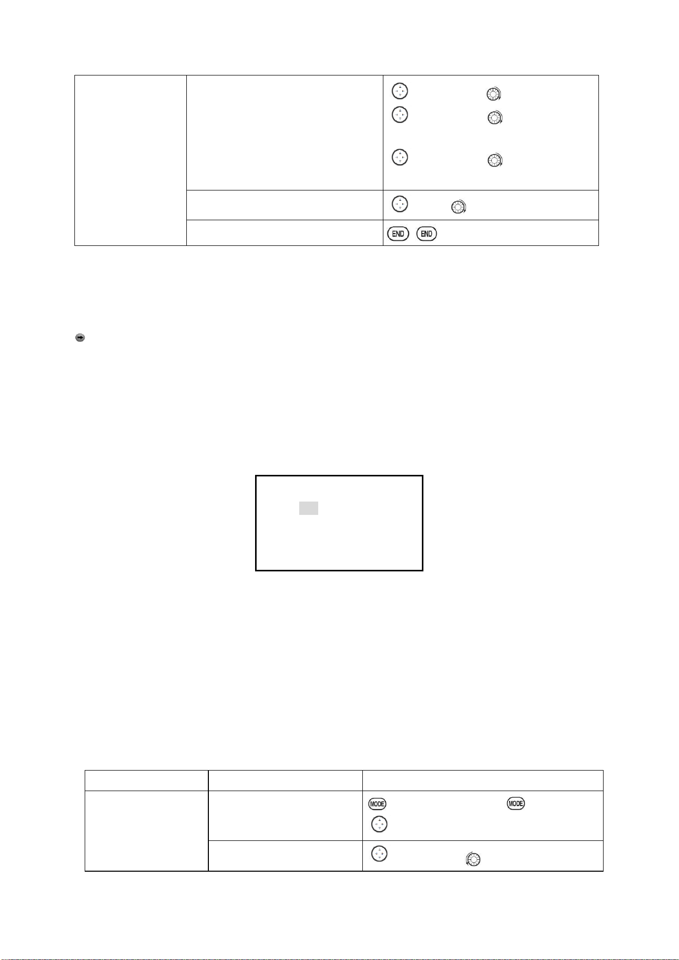
Radiolink Electronic Ltd
www.radiolink.com
27
engine stops. (NOTE:
you MUST assign a
switch to control
which default is
NULL)
Activate the function Choose desired
switch, and the position.
to MIX,PUSH, to ON,PUSH
to SW,PUSH, to desired SW ,
PUSH
to POSI,PUSH to desired position,
PUSH
Adjust Rate until the engine shuts off.
to Rate. until shuts off.
Close
HELICOPTER
This function is used to stop engine after flight is finished. You can set engine powered on/ off,
without shifting trim stick to power off and set again every time before flight. Throttle shut for
helicopter includes THR ON/ OFF (position above idle down). Before resetting throttle cut, throttle
stick must keep below setting point to avoid a sudden speeding up.
Notification: trigger point setting step: under the menu THR CUT, choose THRO by DIAL, and
press PUSH and move the throttle stick to trigger point, then press and hold PUSH one second to
save. This function only when the throttle stick moves below trigger point.
2.3.9 IDLE DOWN (ACRO only)
Lowers the engine idle for: set for sitting on the runway prior to take off, stalls and spins, and
landings. The normal idle setting is a little higher for easier starts and safe flights with less risk of
dead sticks.
【IDLE DOWN】
MIX:INH
RATE: 0%
SW:SwC
POST:Ct&Dn
Important note: The IDLE-DOWN function is not normally used when starting the engine, and its
accidental operation may keep your engine from starting. The AT10II warns that IDLE-DOWN is on
when the transmitter is turned on. Be sure to turn off the function, or override the warning by
pressing CURSOR lever if you intended the function to be on.
This may be assigned to any switch/position. Some modelers accidentally assign IDLE-DOWN to
one side of a switch and THR-CUT to the other. There is no "normal" setting to start the engine. By
default IDLE-DOWN is get to SWITCH C center and down. This works well with THR-CUT also on
SWITCH C down. The SWITCH C up is normal flight/starting, center for slower maneuvers/landing,
and down to cut the engine. If you assign IDLE-DOWN or THR-CUT to the spring-loaded TRAINER
SWITCH H or F, then use the trainer function, you may risk loss of throttle control or dead stick for
your student.
Goals
Steps
Inputs
Decrease the throttle
setting to idle with the
flip of a switch for spins
and landings.
Open BASIC menu,open
IDLE DOWN
for 1s .(If ADVANCE again) .
to IDLE DOWN,PUSH.
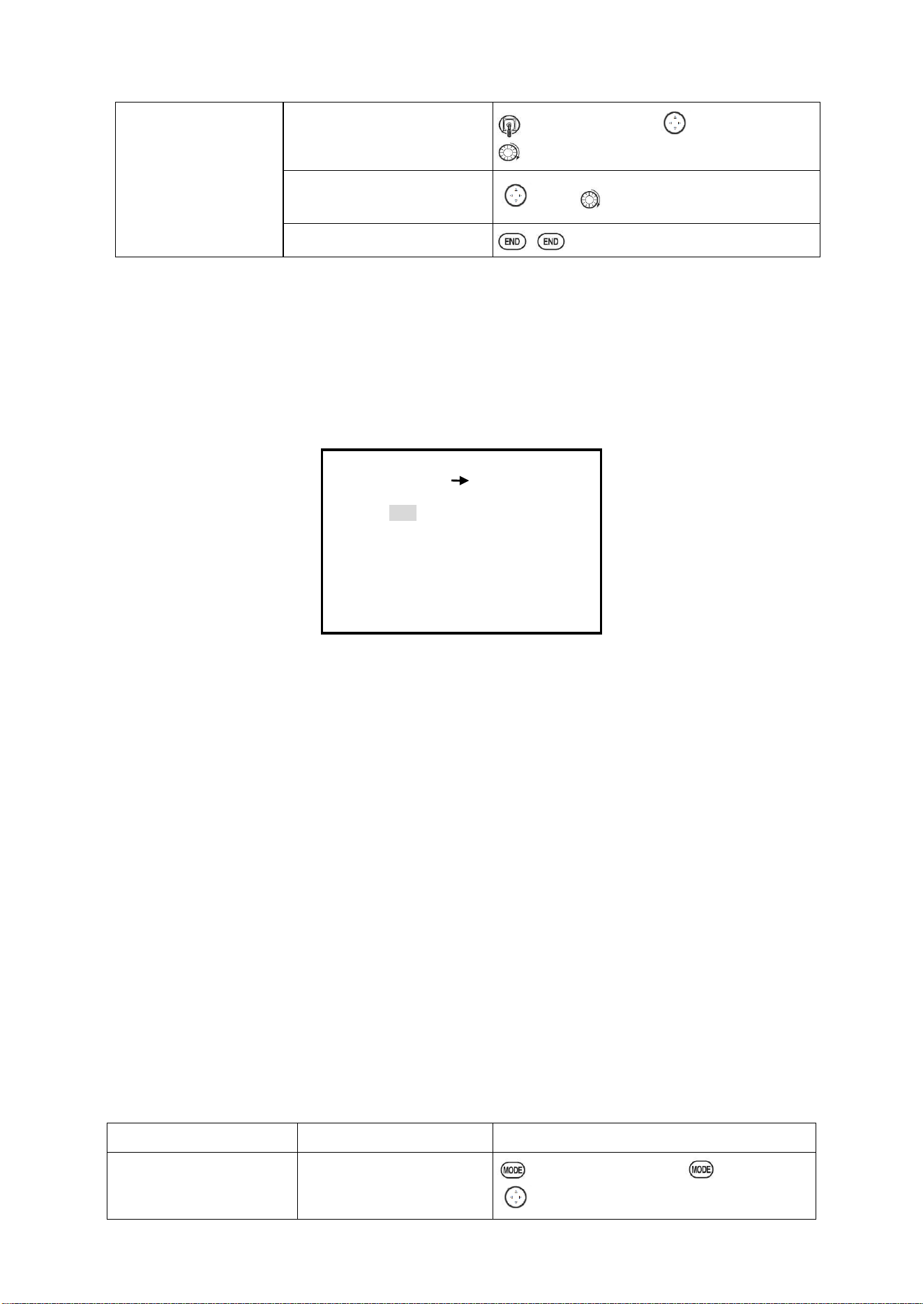
Activate the function
to MIX,PUSH
,
to OFF
Radiolink Electronic Ltd
www.radiolink.com
28
Adjust the rate until engine
idles as desired with Throttle
stick.
Throttle Stick down, to RATE,PUSH,
to desired rate, PUSH
Optional:change switch
assignment .
to SW, to desired position, PUSH.
Close
*Normally a value of 10- 20%. Secure the fuselage, engine running. Set the THROTTLE STICK to
idle. Adjust the IDLE-DOWN switch ON and OFF until the desired idle is achieved. Be sure to
throttle up periodically to allow the engine to “clean out” and idle reliably.
*Also LOGIC SW (Lsw1 to 3) may be assigned.
2.3.10 Fail Safe (F/S) (loss of clean signal and low receiver battery) submenu (F/S): sets
responses in case of loss of signal or low Rx Battery.
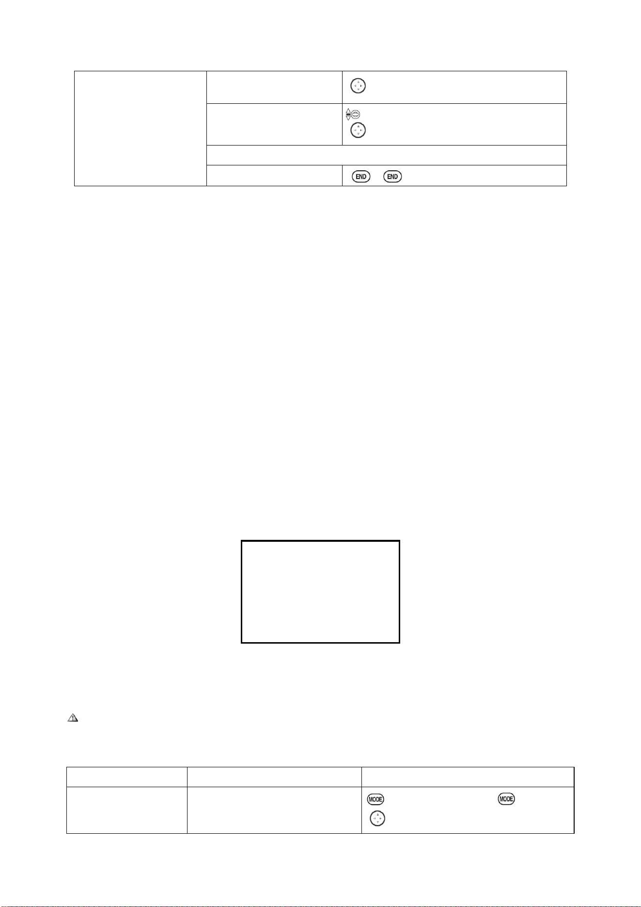
【F/S】
1:AILE NOR
CH1:
AILE
2:ELEV NOR
NOR
F/S
3:THRO 15%
4:RUDD NOR
CH9:
NOR
5:GEAR NOR
CH10:
NOR
6:FLAP NOR
CH11:
NOR
7:AUX1 NOR
CH12:
NOR
8:AUX2 NOR
Adjustability:
•Each channel may be set independently.
• The NOR (normal) setting holds the servo in its last commanded position.
• The F/S (Failsafe) function moves each servo to a predetermined position.
• NOTE: the setting of the throttle's F/S also applies to the Battery F/S.
• The F/S is used in certain competitions to spin the MULTIROTOR to the ground prior to flying
away and doing potential damage elsewhere. Conversely, may also be used to go to neutral on all
servos, hopefully keeping the plane flying as long as possible.
• Competition modelers often maintain the NOR function so that brief interference will not affect
their model's maneuver.
• Set the throttle channel so that the engine idles when there is interference (ACRO). This may
give enough time to fly away from and recover from the radio interference and minimize damage if
crashed.
• For helicopters, NOR is typically the safest choice.
•We also recommend setting a gasoline engine's electronic kill switch to the OFF position in the
F/S function for safety reasons.
If you specify a F/S setting, the Failsafe data is automatically transmitted once each two minutes.
(PCM) When you choose the F/S mode, check that your settings are as desired by turning off the
transmitter power switch and verifying that the servos move to the settings that you chose. Be sure
to wait at least two minutes after changing the setting and turning on the receiver power before
turning off the transmitter to confirm your changes have been transmitted.
Goals
Steps
Inputs
Change the receiver
Failsafe command for
channel 8(gasoline engine
Open BASIC menu, then
Open F/S.
for 1s .(If ADVANCE again) .
to F/S, PUSH
Radiolink Electronic Ltd
www.radiolink.com
29
kill switch) to a preset
position. NOTE: This is
one of several functions for
which the radio requires
confirmation to make a
change.
Choose channel to
change(Ex:CH.8)
to CH8 ,PUSH
Set and confirm fail safe
command.
that controls CH8 to desired OFF position.
to adjust ,PUSH
Repeat as desired
Close
2.3.11 Auxiliary Channel Function (including channel 9-12 controls)
(AUX-CH): defines the relationship between the transmitter controls and the receiver output for
channels 5-12. Also, the CH9-12 POSI are used to change the CH9-12 servo direction.
Note that the CH9-12 functions are only visible in the AUX-CH screen and modulation mode must
be PCM or 2.4G.
Adjustability:
Auxiliary channel: The auxiliary channel switch is used to do some auxiliary functions, such as
opening or closing the throwing chamber, opening or closing the control machine that releases
smoke, etc. Each auxiliary channel can be customized with any switch, slider or knob to control
(The slider knob is usually used in the pan/tilt camera), or multiple channels can be set on the same
switch, slider or knob, and the setting effect can be viewed on the'rudder amount display' interface
of the remote control.
Vehicle and ship models generally have 2 basic channels, and airplane models generally have
4 basic channels. All channels except for the basic channels of the remote control are auxiliary
channels.
AT10II can not only customize the auxiliary channels, but also customize the 4 basic channels
to meet the personalized needs of model friends to a greater extent. The specific setting methods
are as follows:
Long press the Mode button for 1 second to enter the basic menu, turn the CURSOR button to
select'System Settings', tap the Push button for 1 second to enter the'System Settings' menu, then
select the'Joystick Mode' to "—", tap End once Key to return to the basic menu interface, and then
use the CURSOR key to select "auxiliary channel" to see the following interface.
【AUX-CH】
CH1:STK1
CH2:STK2
CH3:STK3
CH4:STK4
CH11:SwD
CH12:VrE
CH5:SwF
CH6:----
CH7:SwC
CH8:VrB
CH9:SwB
CH10:SwA
Related channels:
GYRO SENSE (ACRO): CH. 5, 7, or 8
GYRO SENSE (HELI): CH. 5
GOVERNOR (HELI): CH. 7, or CH. 7 and 8
THR-NEEDLE (ACROHELI): CH. 8
Remember that if you assign primary control of a channel to a switch which you later use for
other functions (like dual/triple rates or airbrakes), every time you use that other function you will
also be moving the auxiliary channel.
Goals
Steps
Inputs
Assign flaps to the right
slider[VR(E)] and set
channel 7 to NULL in
Open BASIC menu, then to
AUX-CH
for 1s .(If ADVANCE again) .
to AUX-CH,PUSH
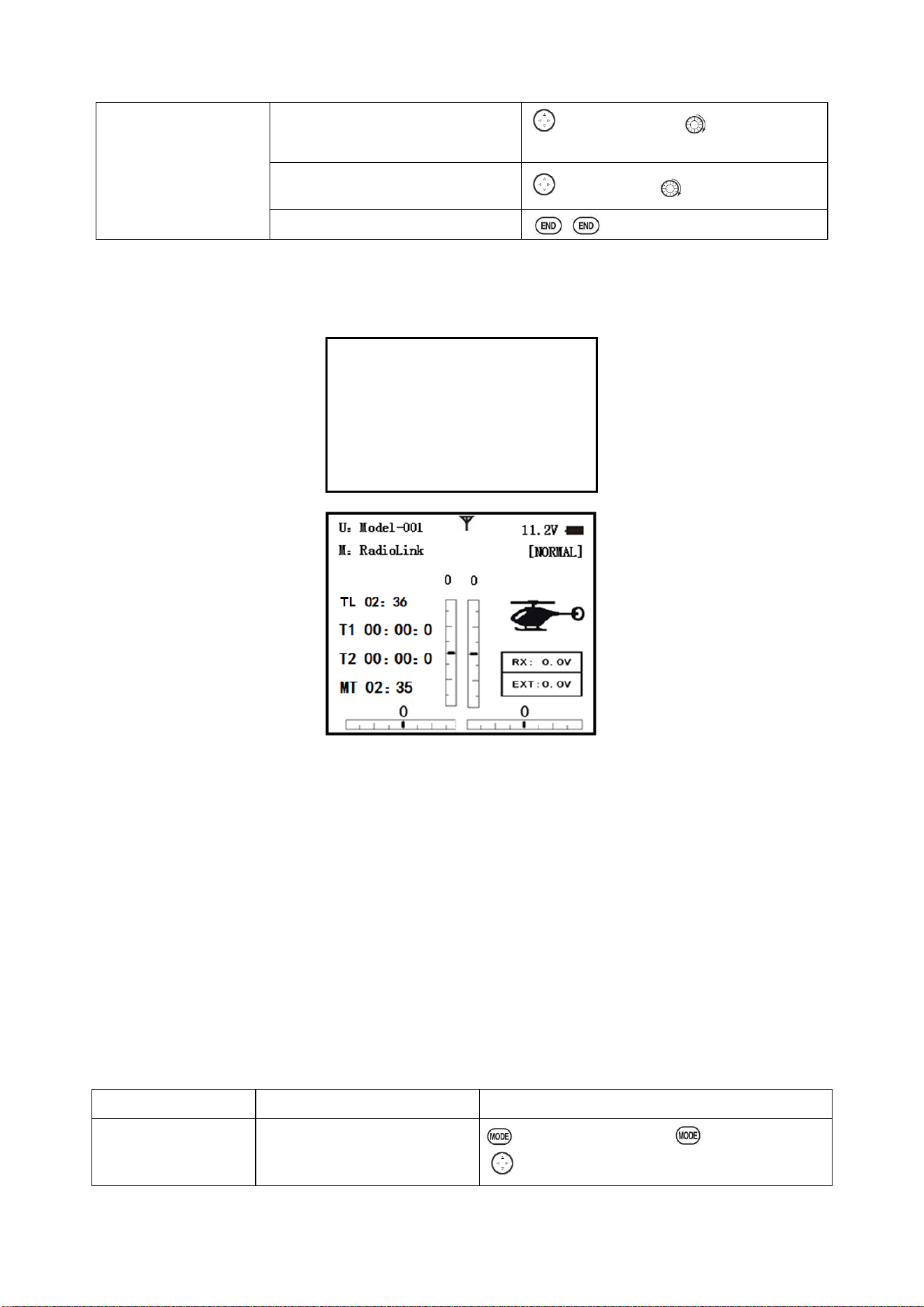
Radiolink Electronic Ltd
www.radiolink.com
30
preparation to use it as a
smoke system control
(the smoke system being
activated later by a
throttle to CH7 MIX).
Choose channel to change (Ex:CH6)
to CH6,PUSH, to desired switch,
PUSH
Repeat above steps as desired.
(Ex:CH7=NULL)
to CH7,PUSH, to NUL
Close
2.3.12 TIMER sub-menu (stopwatch functions):
Controls three electronic clocks used to keep track of time remaining in a competition time allowed,
flying time on a tank of fuel, amount of time on a battery, etc.
【TIMER】
<1>OFF
<2>OFF
<3>ON
TIME:10:00
10:00
---
MODE:UP
UP
MODEL
ON:
SwA
SwA
---
NULL
NULL
---
RSET:
SwA
SwA
---
NULL
NULL
---
Adjustability:
• Count down timer: starts from the chosen time, displays time remaining. If the time is exceeded, it
continues to count below 0.
• Count up timer: starts at 0 and displays the elapsed time up to 99 minutes 59 seconds.
• Count down timer (Stop type): starts from the chosen time, displays time remaining, and stops at
0.
• Model timer: cumulates ON time up to 99 hours 59 minutes each model. Once Model timer
function is turned off, the cumulate time will also be reset to "0:00".
• Independent to each model, and automatically updates with model change.
•In either TIMER mode, the timer will beeps During the last twenty seconds, there's a beep each
second, A long tone is emitted when the time selected is reached. (UP/DOWN TIMER)
• To Reset, choose the desired timer with the CURSOR lever (while at the start-up screen), then
press and hold DIAL for 1 second.
• Activation by either direction of SWITCH A-H, by THROTTLE STICK (STK-THR) (Using the
THROTTLE STICK is convenient if you are keeping track of fuel remaining, or for an electric, how
much battery is left), by LOGIC SWITCH Lsw1-Lsw3 or by the power SWITCH (PWR SW).
• Also the reset switch can be assigned (SWITCH A-H or LOGIC SWITCH Lsw1-Lsw3)
Goals
Steps
Inputs
Set timer 2 to count
down 4 1/2 minutes,
being controlled by
Open BASIC menu, then to
TIMER
for 1s .(If ADVANCE again) .
to TIMER ,PUSH
Radiolink Electronic Ltd
www.radiolink.com
31
Throttle Stick position.
This utilized to keep
track of actual Throttle
on time to better
cooperate with
fuel/battery usage.
Go to TIMER <2>
to TIMER <2> ,PUSH
Adjust time to 4min.30sec.,
count down
to 4,PUSH.
to 00 TIMER<2>, PUSH to 30,PUSH
Assign switch at ST-THK and
set trigger point.
to SWA TIMER<2>, to ST-THK,PUSH
Throttle Stick down to 50%,PUSH for 1s to
NULL.
Throttle Stick down to desired position(Ex:1/4
stick) PUSH button for 1s to set.
Close
2.3.13 TRAINER:
For training novice pilots with optional trainer cord connecting 2 transmitters. The instructor has
several levels of controllability.
【TRAINR】
MIX: INH
1:AILE NORM
2:ELEV NORM
3:THRO NORM
4:RUDD NORM
5:GEAR NORM
6:FLAP NORM
7:AUX1 NORM
8:AUX2 NORM
Adjustability:
• NORM: When the TRAINER SWITCH is ON, the channel set to this mode can be controlled by
the student. The set channel is controlled according to any programming set at the student's
transmitter.
• FUNC: When the TRAINER SWITCH is ON, the channel set to this mode can be controlled by
the student, controlled according to any mixing set at the instructor's transmitter.
• MIX: When the TRAINER SWITCH is ON, the channel set to this mode can be controlled by both
the student and the instructor, controlled according to any mixing set at the instructor's transmitter.
And the student's mixing rate is adjustable. (Default 30%)
[Note] However, it becomes invalid even if it sets up the channel which is not in a student's
transmitter. The channel serves as operation by the instructor's transmitter automatically.
• OFF: The channel set to this mode cannot be controlled by the student even when the TRAINER
SWITCH is ON. The set channel is controlled by the instructor only, even when the TRAINER
SWITCH is ON.
• SWITCH: controlled by spring-loaded SWITCH H only. Not assignable.
• Compatibility: The AT10 may be master or student with any Radiolink transmitter compatible with
the cord. Simply plug the optional trainer cord (For AT10 series, sold separately) into the trainer
connection on each transmitter, and follow the guidelines below.
EXAMPLES:
•When throttle/collective is set to FUNG, 5-channel helicopter practice is possible with a 4-channel
transmitter.
• Set up the model in a second transmitter, use NORM mode to quickly and safely check proper
operation of all functions, and then allow the student radio to fully fly the model.
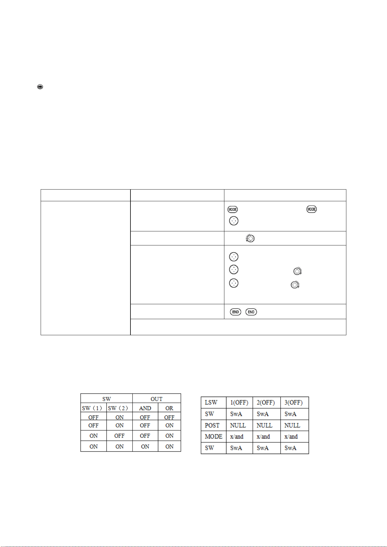
Radiolink Electronic Ltd
www.radiolink.com
32
• Using NORM mode, set lower throws, different exponentials, even different auxiliary channel
settings on the student radio (if it has these features).
• To ease the learning curve, elevator and aileron may be set to the NORM or FUNC mode, with
the other channels set to OFF and controlled by the instructor.
NOTE:
• NEVER turn on the student transmitter power.
•ALWAYS set the student transmitter modulation mode to PPM.
• BE SURE that the student and instructor transmitters have identical trim settings and control
motions. Verify by switching back and forth while moving the control sticks.
• FULLY extend the instructor's antenna. Collapse the student's antenna. (Except 2.4GHz)
• When the TRAINER function is active, the snap roll function is deactivated. Other functions, such
as IDLE-DOWN and THR-CUT, which have been assigned to the same switch, are not deactivated.
Always double check your function assignments prior to utilizing the TRAINER function.
•When you select a different model, the TRAINER function is deactivated in the current model for
safety reasons.
Goals
Steps
Inputs
Turn on the TAINER system
and set up so student has :fully
functional control of aileron
and elevator to support
FLAPERON &AILERON;
normally control of rudder to
allow lowered travel; and no
throttle channel control(with
the instructor for safety)
Open BASIC menu, then Open
TRAINER
for 1s .(If ADVANCE again) .
to TRAINER ,PUSH
Activate TRAINER
PUSH, to PUSH
Choose desired channels and
proper training types
past AILE and ELE(default FUN)
to THRO,PUSH, to OFF, PUSH
to RUDD, PUSH, to
NORM,PUSH
Close
Test student radio function prior to attempting to fly!
2.3.14 Logic Switch Selection (LOGIC SW):
The various functions in the AT10II can be selected by switch..
The Logic switch can be assigned to the functions as following: THR-CUT, IDLE DOWN, AUX-CH,
TIMER, PROG. MIX, AIRBRAKE, ELEV-FLAP, and AILE-FLAP. The logic switch can activate
functions by two switches combination. The 2 types of logic, either AND or OR, can be selected.
Adjustability:
• Three logic switches can be used. (LSW1, LSW2, and LSW3 )
• SW (1): Any SWICH A-H or THRSTKS, SW (2): Any SWICH A-H
• Switch position (POSI)
• Logic mode: AND or OR (MODE)
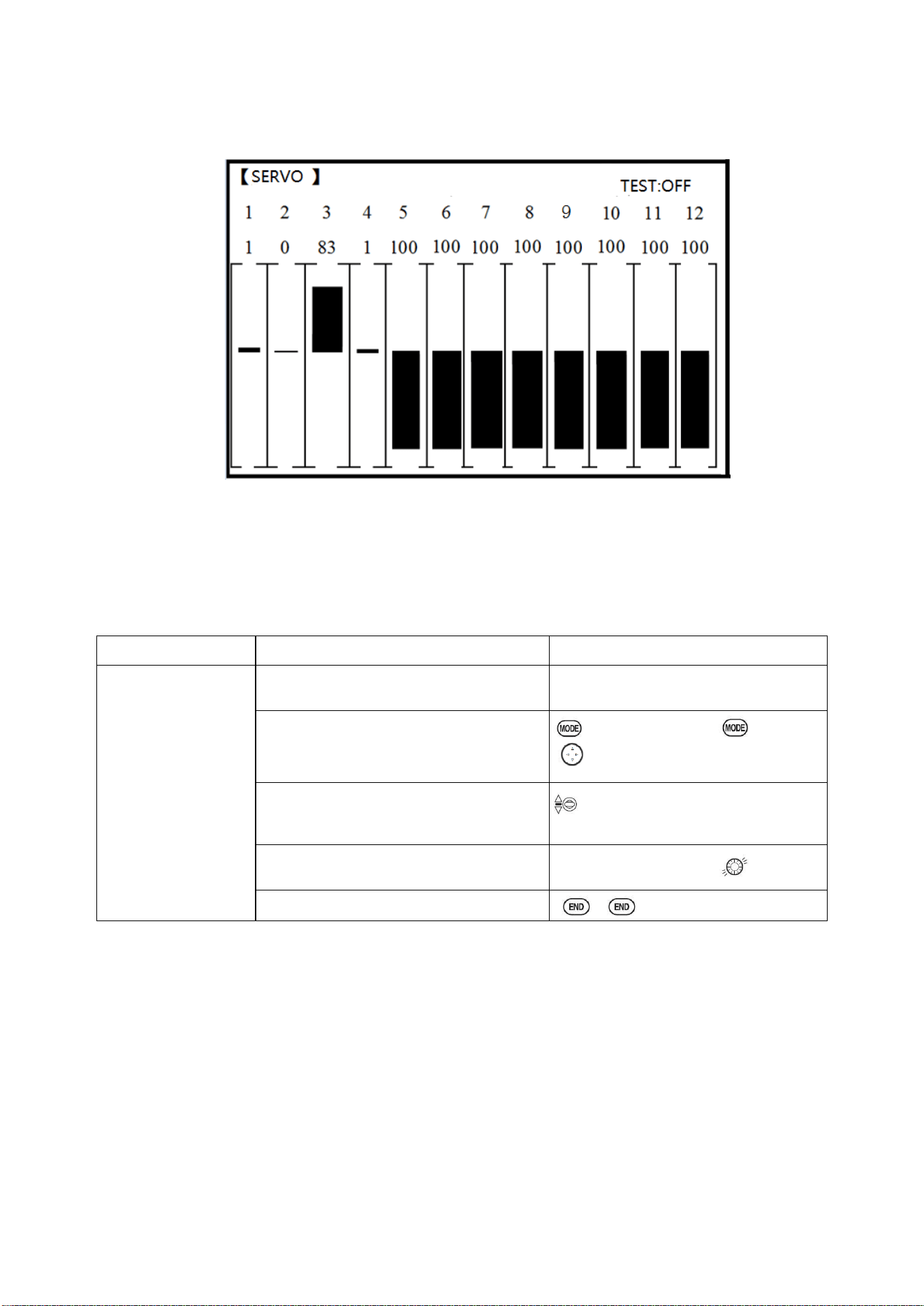
Radiolink Electronic Ltd
www.radiolink.com
33
2.3.15 SERVO display and cycle sub-menu:
Displays radio's output to channels 1-12.
The servo sub-menu includes two features:
• Real-time bar-graph display to demonstrate exactly what commands the transmitter is sending to
the servos. (This can be particularly handy in setting up models with complicated mixing functions,
because the results of each stick, lever, knob, switch input and delay circuit may be immediately
seen.)
• Servo cycle function to help locate servo problems prior to in-flight failures. (Channels 1-12)
Goals
Steps
Inputs
View the result of
reassigning channel 6
from VR(A) knob to
three-position
SWITCH C
Cycle the channel 6
servo.
Complete desired programming
function.(Ex: in AUX-CH,move ch.6 to
SWITCH C)
See AUX-CH for details.
Open SERVO function
for 1s .(If ADVANCE again) .
to SERVO , PUSH
Move each control to see the
operation.(Ex: SWITCH C in all positions)
C to center position. Note change in
position of ch.6 servo.
Prepare all servos to be cycled and cycle
Plug in servos. Power on.
Close
2.3.16 TELEMETARY
Signal strength and receiver voltage integrated into the radio transmitter. It is displayed as the
following configure, also it is in the sub menu RECEIVE.
Receiver voltage is shown as RX,
External voltage is shown as EXTY.
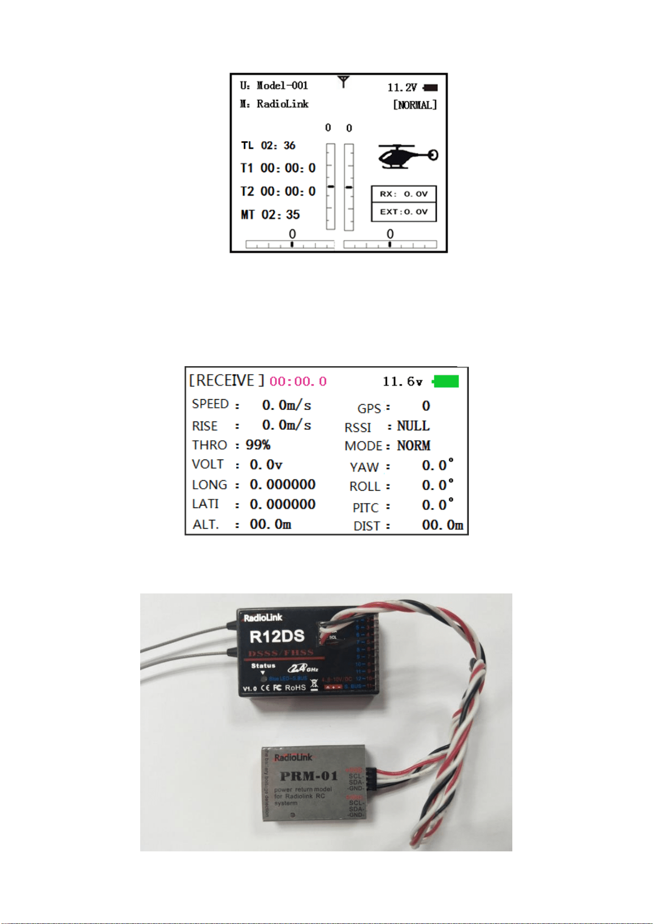
Radiolink Electronic Ltd
www.radiolink.com
34
Find telemetry information: under BASIC MENU, select RECEIVE, presses PUSH to enter, you can
find the telemetry info, shown as below. RX is receiver voltage, EXT is external voltage. Also
temperature and engine speed (EXT, TEMPERATURE, RPM, and GPS all need telemetry sensor).
RSSI is signal strength, NULL is for no signal, and 0 is for max.
Connection of telemetry sensor: sensor of EXT, TEMPERATURE, RPM, GPS can connect one by
one with the receiver port DATA.
Linkage as below:
Connect to telemetry module PRM-01
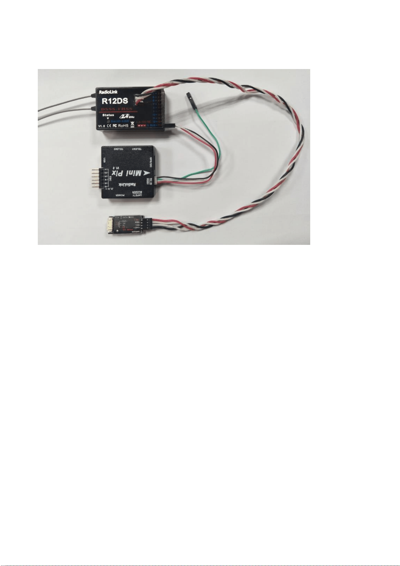
Radiolink Electronic Ltd
www.radiolink.com
35
Connect to telemetry module PRM-03(the product in the middle is flight controller Mini Pix from
Radiolink)
Part 3. ACRO ADVANCE MENU FUNCTIONS
3.1 AIRPLANE WING TYPES (ACRO/GLID):
There are 3 basic wing types in MULTIROTOR models:
• Simple. Model uses one aileron servo (or multiple servos on a Y-harness into a single receiver
channel) and has a tail. This is the default setup and requires no specialized wing programming.
• Twin Aileron Servos. Model uses 2 aileron servos and has a tail. See TWIN AILERON SERVOS.
• Tail-less models (flying wing). Model uses 2 wing servos working together to create both roll and
pitch control. See ELEVON.
Twin Aileron Servos (with a tail) (ACRO/GLID): Many current generation models use two aileron
servos, plugged into two aileron servos, plugged into two separate receiver channels. (If your model
is a flying wing without separate elevators, see ELEVON)
ADVANTAGE:
• Ability to adjust each servo's center and end points for perfectly matched travel.
• Redundancy, for example in case of a servo failure or mid-air collision.
• Ease of assembly and more torque per surface by not requiring torque rods for a single servo to
drive 2 surfaces.
• Ease of assembly and more torque per surface by not requiring torque rods for a single servo to
drive 2 surfaces.
• Having more up aileron travel than down travel for straighter rolls, aileron differential. (See
glossary for definition.)
• Set a negative percentage to reverse the operation of one of the servos.
Options:
• 5-channel receiver. Set up AILE-2 prior to continuing with FLAPERON or AIL-DIFF.
• FLAPERON:
•Uses CH6 for the second servo
• Allows flap action as well as aileron action from the ailerons.
• Provides FLAP-TRIM function to adjust the neutral point of the FLAPERON for level flight.
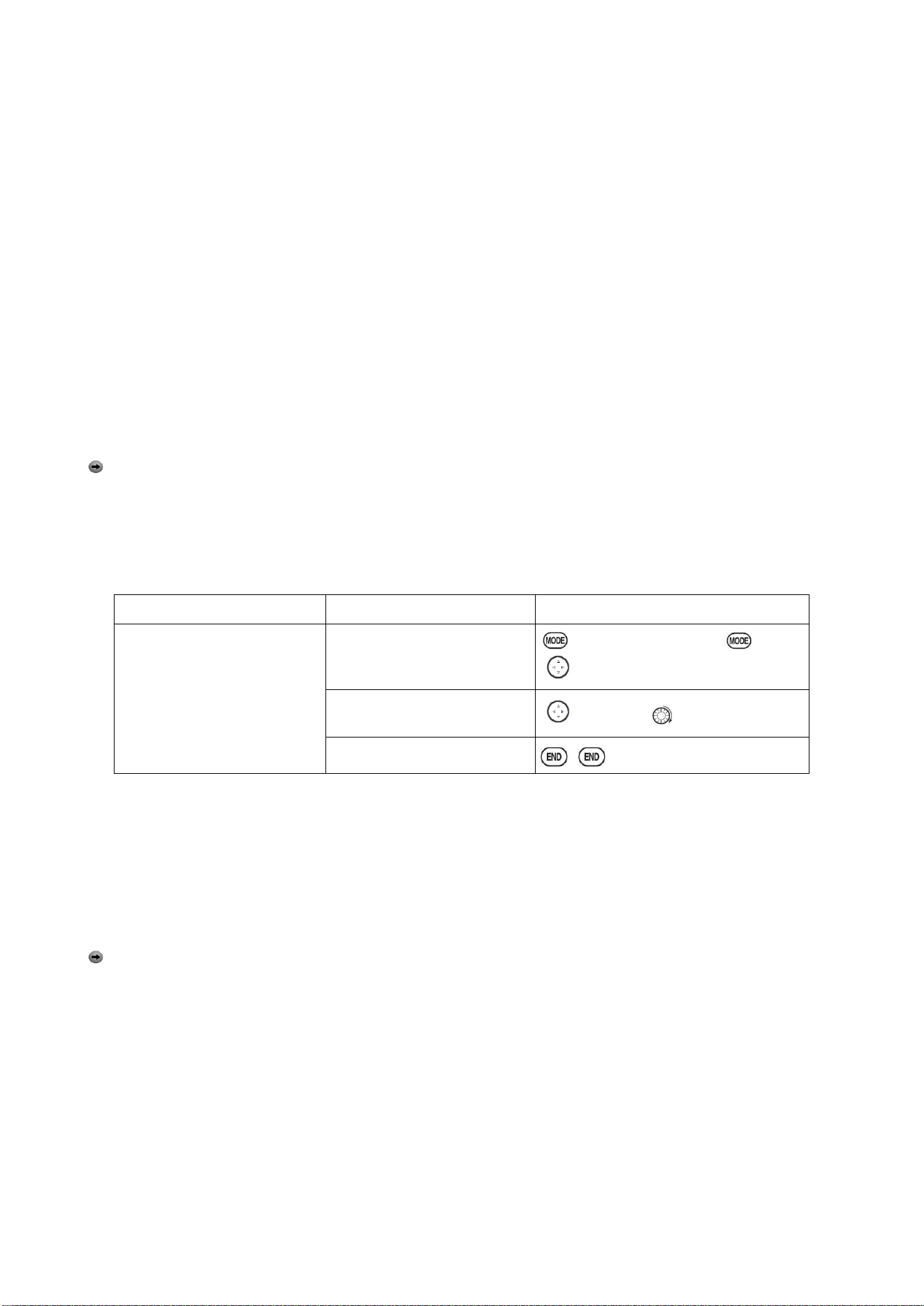
Radiolink Electronic Ltd
www.radiolink.com
36
• Also allows aileron differential in its own programming (instead of activating AIL-DIFF).
• Uses CH7 for the 2nd servo (see AIL-2 use CH5)
• Leaves CH5 & CH6 free for flap operation, such as FLAPERON and flap action together, in
AIRBRAKE.
• Allows for more up aileron travel than down for straighter rolls. You will need to choose which of
FLAPERON or AIL-DIFF is better for your model's setup. If you need the ailerons to also operate as
flaps, you most likely want to use FLAPRON. If your model has 2 aileron servos and flaps, then
AIL-DIFF is probably the easiest choice.
NOTE: Only one of the three wing-type functions (FLAPERON, AIL-DIFF, and ELEVON) can be
used at a time. All three functions cannot be activated simultaneously. To activate a different wing
type, the first must be deactivated.
3.2
TWIN AILERON SERVOS (5-channel receiver, AILE-2 , ACRO/GLID)
AILE-2 allows FLAPERON and AIL-DIFF with a 5-channel receiver. AILE-2 only tells the radio that
you are using CH5 and CH6 (FLAPERON), or CH5 and CH7 (AILDIFF), not CH6 or CH7, as the
second servo in FLAPERON or AILE-DIFF. You still must activate and set up the
FLAPERON/AILE-DIFF function.
Note that selecting CH6&5 or CH7&5 does NOT free up CH6 or CH7 to be used for other
functions when using a receiver with more than 5 channels. Both 5 and 6 (FLAPERON/AILE-DIFF)
are dedicated to the FLAPERON or AILE-DIFF programming. [This is beneficial with four aileron
servos that need to have their end points or sub-trims set separately. CH1, CH5 and CH6 are
already fully set up to operate as ailerons. Mix the CH7 or CH8 (the second aileron servo on the
other side) into ailerons to function properly.
Goals
Steps
Inputs
Adjust the 2
nd
aileron servo
output from CH6or7 to
channel CH6&5 Allow twin
aileron servos operating with a
5-channel receiver.
Open PARAMETER
submenu.
For 1s. (If ADVANCE again) .
to PARAMETER ,PUSH
Select AILE-2 and change to
CH6&5.
To AILE-2. to CH6&5
Close
There are 4 basic tail types in MULTIROTOR models:
• Simple. Model uses one elevator servo and one rudder servo (or multiple servos on a Y-harness).
This is the default.
• Dual Elevator servos. Model uses 2 elevator servos.
• Tail-less models. Model uses 2 wing servos together to create roll and pitch control. See ELEVON
(ACRO/ GLID 1A+1F).
• V-TAIL. Model uses 2 surfaces, at an angle, together to create yaw and pitch control. see V-TAIL
(ACRO/ GLID).
Note
: Only one of the three tail-type functions (AILEVATOR, V-TAIL, and ELEVON) can be used
at a time. The radio provides a warming and will not allow the activation of another tail type until the
first is deactivated. An error message of OTHER WING MIXING IS ON will display.
Using ELEVON (ACRO/GLID 1A+1F): it is used with delta wings, flying wings, and other tailless
MULTIROTOR that combine aileron and elevator functions, using two servos, each one on the
ELEVON. The aileron/elevator responses of each servo can be adjusted independently. This is also
popular for ground model use, such as tanks, which drive two motors together for forward, and one
motor forward/ one backward for turning.
3.3 ACRO ADVANCE FUNCTION MENU
Mixes are special programs within the radio that command one or more channels to act together
with input from only one source, such as a stick, slider or knob.
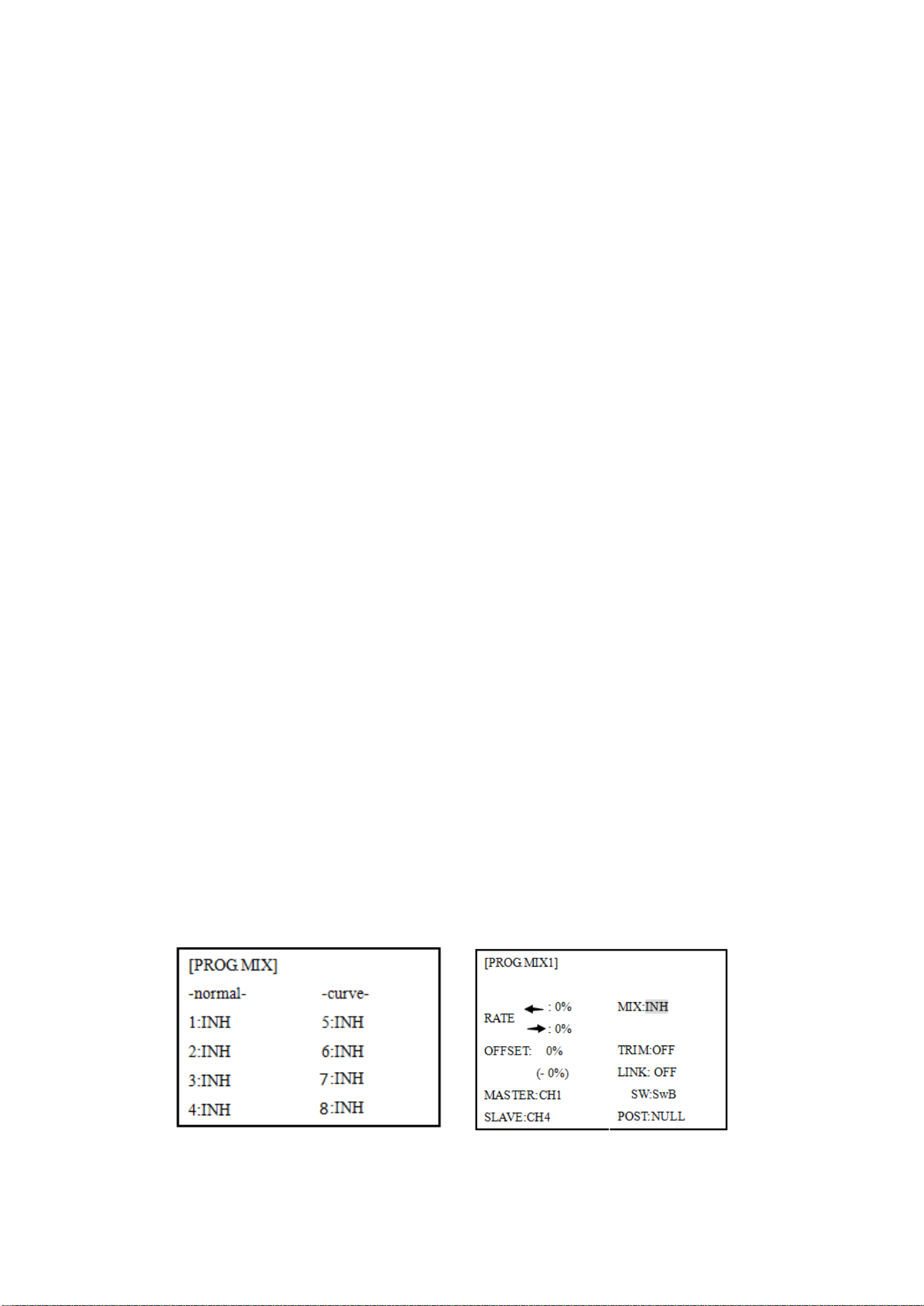
Radiolink Electronic Ltd
www.radiolink.com
37
There are a variety of types of mixes:
TYPE:
• Linear: Most mixes are linear. A 100% linear mix tells the slave servo to do exactly what the
master servo is doing, using 100% of the slave channel’s range to do so. An example is
FLAPERON, when aileron stick is moved, the flap servo is told to move exactly the same amount. A
50% linear mix would tell the slave servo, for example, to move to 50% of its range when the
master’s control is moved 100%.
• Offset: An OFFSET mix is a special type of linear mix. When the mix is turned on (usually a flip of
a switch), the slave servo is moved a set percent of its range. An example of this is AIRBRAKE,
moving flaps, FLAPERON, and elevator all to a set position at the flip of a switch.
• Curve: Curve mixes are mostly used in helicopters, but may also be used in airplanes and gliders.
An example is THROTTLE-NEEDLE mixing, where the in-flight needle’s servo is moved, changing
the mixture, as the throttle servo is moved.
• Delay: Delay mixes are part of a few very special functions that make the servo move to its desired
range more slowly.
THROTTLE DELAY (simulates turbine engines) and the elevator delays in AIRBRAKE are two
examples of this. DELAY in HELI is another example that slows the servo movement to the trim
settings for the other conditions.
Essentially every feature in the radio's programming is really a mix, with all
assignments/programming set up and ready to use. Additionally, the AT10II ACRO and GLID
programs both provide 4 linear and 4 curve fully-programmable mixes ( HELI provides 4 linear and
2 curve) that allow you to set up special mixes to resolve flight difficulties, activate additional
functions, etc.
Let’s look quickly at a few examples that are features we’ve already covered. This may help to
clarify the mix types and the importance of mixes:
Additional example:
• Exponential is a preprogrammed curve mix that makes the servos’ response more (+) or less (-)
sensitive around center stick (works in conjunction with dual rate, a linear mix that adjusts the total
range). see D/R,EXP,
• IDLE-DOWN and THR-CUT are two OFFSET pre-programmed mixes. These tell the throttle servo,
when below a certain point, to move toward idle an additional set percentage to help close the
carburetor.
• ELEV-TO-FLAP mixing is a pre-programmed linear mix to move the flaps proportionally to elevator
control, helping the model loop even tighter than it can on elevator alone.
• THROTTLE-NEEDLE mixing is a curve mix (like PROG.MIX 5 to 8) for proper in-flight needle
setup.
• THROTTLE DELAY mixing is a pre-programmed delay mix that slows down the response of the
CH3 servo.
Next, we'll get an in-depth look at some pre-programmed mixes (mixes whose channels are
predefined for simplicity) we’ve not covered yet, and last, look at the fully-programmable mix types.
3.3.1 Program MIX
AT10II contains four separate linear programmable mixes. (Note that mixer #5-8’s mixing RATE are
set with a 5-point curve. HELI has mixer #5-6's mixing. See CURVE MIXES
There are a variety of reasons you might want to use these mixes. A few are listed here. All of the
adjustable parameters are listed below, but don’t let them scare you. For your first few times

Radiolink Electronic Ltd
www.radiolink.com
38
experimenting with mixes, just turn on the default mixes, adjust them how you think they need to be,
then use the servo screen to check and see if you were correct. As with all functions, a sample
setup follows, step by step, to assist you.
Sample reasons to use linear programmable mixes:
• To correct bad tendencies of the MULTIROTOR (such as rolling in response to rudder input).
• To operate 2 or more servos for a single axis (such as two rudder servos).
• To automatically correct for a particular action (such as lowering elevator when flaps are lowered).
• To operate a second channel in response to movement in a first channel (such as increasing the
amount of smoke oil in response to more throttle application, but only when the smoke switch is
active).
• To turn off response of a primary control in certain circumstances (such as simulating one engine
flaming -out on a twin, or throttle-assisted rudder turns, also with a twin).
Adjustability:
• Defaults: The 4 programmable mixes default to the most frequently used mixes for simplicity. If
you want to use one of these mixes, simply select that mix number so that the master and slave
servos are already selected for you.
• PROG.MIX1 aileron-to-rudder for coordinated turns
• PROG.MIX2 elevator-to-flap for tighter loops (HELI mixes default to ELEV-to-pitch.)
• PROG.MIX3 flap-to-elevator to compensate pitching with flaps (HELI mixes default to
pitch-to-ELEV)
• PROG.MIX4 throttle-to-rudder ground handling compensation
•Channels available to mix: All four mixes may use any combination of CH1-8. (CH9-10 is not
proportional and cannot be mixed.) Offset and dials may also be set to the master channels.
•Master: the controlling channel, the channel whose movement is followed by the slave channel.
•Another channel: Most mixes follow a control channel. (Ex: rudder-to-ailerons, 25%, no switch,
corrects roll coupling.)
MASTER
SLAVE
LINK
TRIM
SWITCH
POSITION
RATE
OFFSET
RUDD
AILE
ON
OFF
ANY
NULL
25%
0
•Offset as master: To create an OFFSET mix, set the master as OFST. (Ex: Move FLAPERON as
flaps 20% of their total throw when SWITCH C is in down position.)
MASTER
SLAVE
LINK
TRIM
SWITCH
POSITION
RATE
OFFSET
OFST
FLAP
ON
N/A
C
DOWN
20%
0
• Dial as master: To directly effect one servo’s position by moving a dial, set the master as the
desired dial. (Ex: create a second throttle trim on left slider.)
MASTER
SLAVE
LINK
TRIM
SWITCH
POSITION
RATE
OFFSET
VR(D)
THRO
OFF
N/A
ANY
NULL
5%
0
•Slave: the controlled channel. The channel is moved automatically in response to the movement of
the master channel. The second channel is in a mix’s name (i.e. aileron-to-rudder).
•Link: Link this programmable mix with other mixes.
Ex: PMIX FLAP-ELEVATOR mixing to correct for ballooning when flaps are lowered, but model has
a V-tail. Without LINK, this mix only moves CH2 elevator when flap is commanded, resulting in a
dangerous combination of yaw and roll. With LINK ON, mixing is applied to both CH2 and CH4.
MASTER
SLAVE
LINK
TRIM
SWITCH
POSITION
RATE
OFFSET
FLAP
ELEV
ON
OFF
ANY
NULL
5
%
0
•Trim: Master’s trim affects slave. Not displayed if master is not CH 1-4, because 5-9 have no trim.
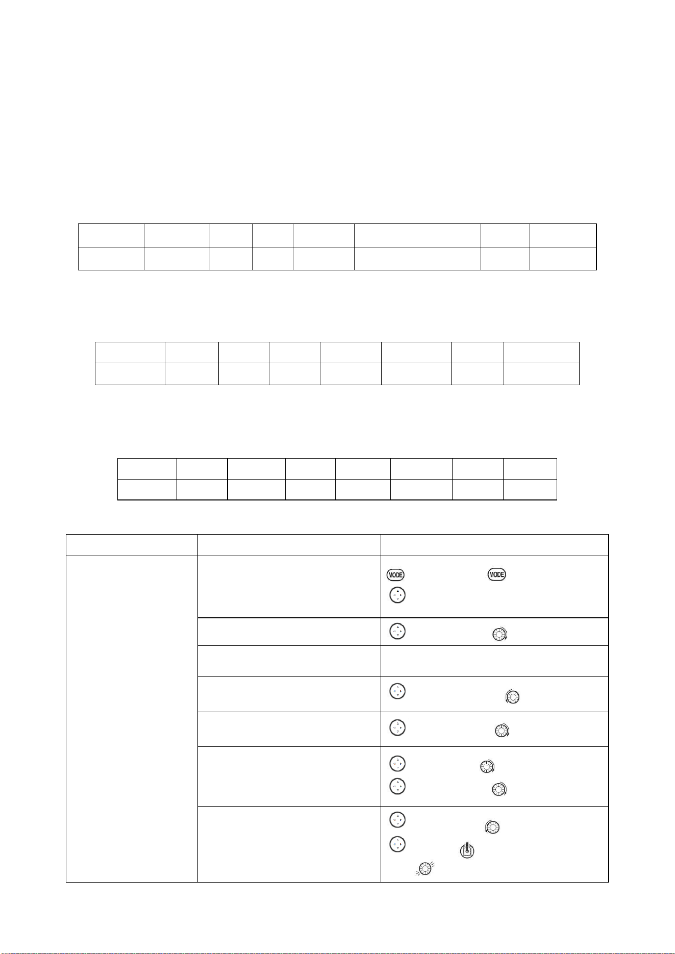
Radiolink Electronic Ltd
www.radiolink.com
39
Ex: two rudder servos. With TRIM OFF, rudder trim would bind the two servos. TRIM ON resolves
this.
• On/off choices:
• SWITCH: Any of the positions of any of the 8 switches may be used to activate a mix. Up&Cntr,
Cntr&Dn options allow the mix to be ON in 2 of the 3 positions of a 3-position SWITCH.
• NULL: No SWITCH can turn this mix OFF. This mix is active at all times.
• LOGIC SW (Lsw1 to 3) may be assigned.
• STK-THR: Turn on/off by THROTTLE STICK movement. Trigger point/direction are selectable. Ex:
OFST-to-(gear doors) mix to open gear doors at idle, which is only active if throttle is below half.
MASTER
SLAVE
LINK
TRIM
SWITCH
POSITION
RATE
OFFSET
OFST
AUX2
OFF
ON
STK-THR
Stick at 1/2.for 1 sec.
100%
0
• Rate: the percentage of the slave’s range it will move upon maximum input from the master
channel. Ex: RUDDERAILERON mix, 50%. Ail range=1''. When rudder is moved full right, ailerons
move 1/2''.
MASTER
SLAVE
LINK
TRIM
SWITCH
POSITION
RATE
OFFSET
RUDD
AILE
OFF
OFF
ANY
NULL
50%
0
• Offset: Offsets the slave’s center is relative to the master. Ex: Smoke valve opens wider per
throttle servo position when smoke SWITCH is ON. Smoke servo’s neutral is moved down from
THROTTLE STICK center to the bottom.
MASTER
SLAVE
LINK
TRIM
SWITCH
POSITION
RATE
OFFSET
THRO
AUX2
OFF
OFF
E
DOWN
100%
100
%
Goals
Steps
Inputs
Set up a FLAP-ELEV
mix:
ON when SWITCH C is
in the down position.
No elevator movement
when flaps move
up(spoilers),5%elevator
movement when flaps
move down. Link should
be ON if mode has twin
elevator servos.
Otherwise, Link remains
OFF.
Open an unused programmable
mix.(Ex: use PROG.MIX3 since it is
already set up for
FLAP-ELEVATOR)
to BASIC menu, again to ADVANCE
to PROG.MIX PUSH
Activate the function
to MIX, PUSH, to ON, PUSH
Choose master and slave channels.
Already CH6 .Already CH2
Optional: set Master as OFST or
VR(A-E)
to Master, PUSH,
to desired choice
Set LINK and TRIM as needed.
to LINK, PUSH , to DWON
Assign SWITCH and position.
(Ex: change from E to C, Down)
to SW, PUSH, to SwC
to POSI, PUSH to DOWN
Optional: set switch to STK-THR to
activate mix with THROTTLE
STICK.
to SW, PUSH to STK-THR
to POSI, Throttle Stick to desired
point .
Push 1sec.to set.
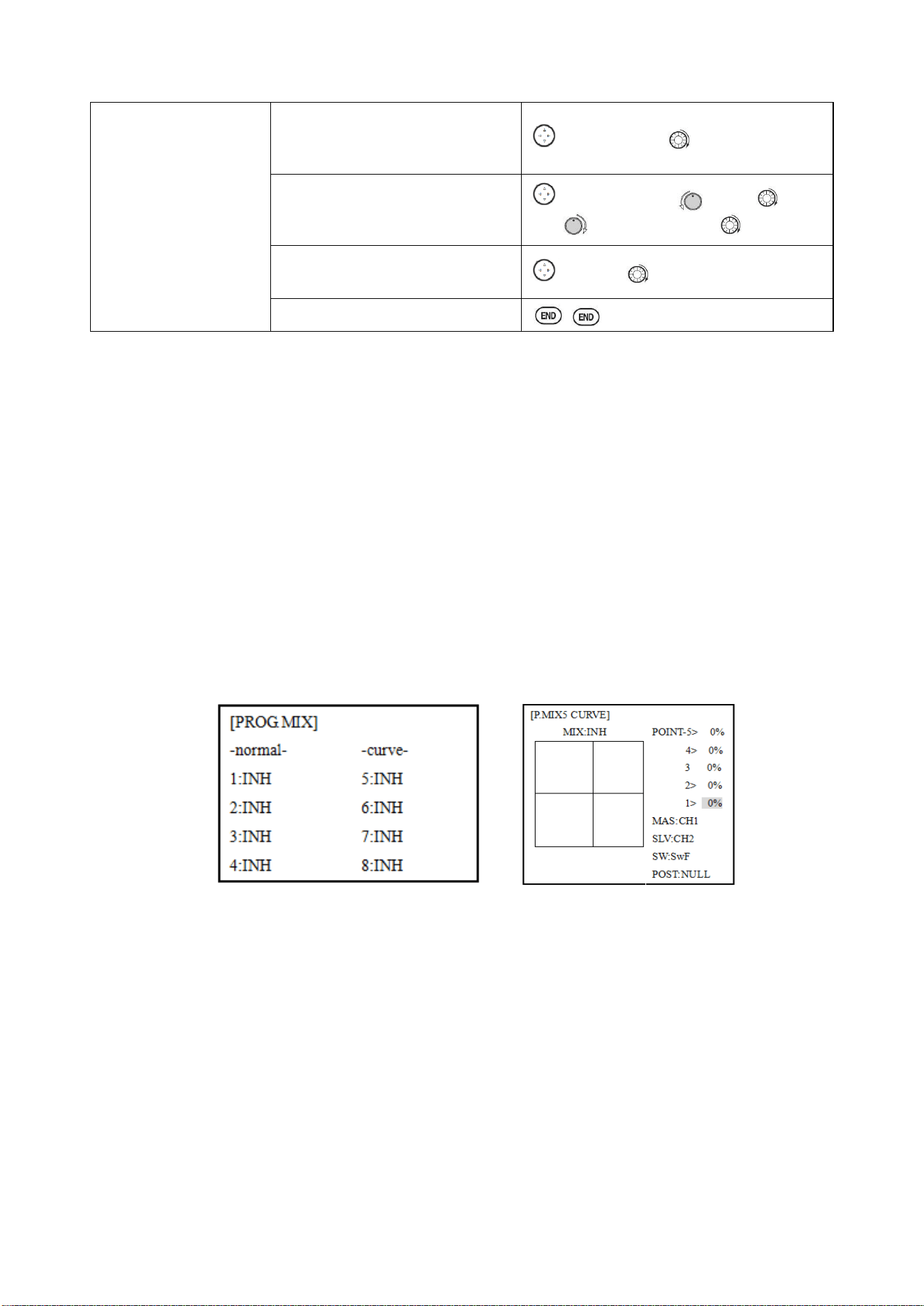
Radiolink Electronic Ltd
www.radiolink.com
40
Optional: set switch position to
NULL. Make mix active at all time.
Not complete with STK-THR.
to POSI, PUSH, to NULL
Set rate. (Ex: Lo=0%,Hi=5%)
to RATE ,PUSH VR(A), leave at
0%, VR(A)past center . to 5%
Set OFF SET, if needed.(Ex:0)
to OFST to 0%
Close
Other samples:
• RUD-ELEV (ACROGLID) mix: Compensate for pitching up or down when rudder is applied.
• AIL-RUD mix (ACRO): Coordinate turns by applying rudder automatically with aileron input. All
model types.
• ELEV-PIT (HELI) mix: Compensate for the loss of lift of tilting the model
3.3.2 Curve Programmable Mixes (PROG.MIX5-8)(HELI: PROG.MIX5-6 ):
AT10’s ACRO/GLID programs contain four separate curve programmable mixes. HELI contains two.
There are a variety of reasons you might want curve mixes. Usually a linear mix doesn't fit your
needs along the whole range. One pre-programmed curve mix is the THROTTLE-NEEDLE function.
This curve is adjustable at 5 points, allowing you to adjust the motor’s tuning at 5 points along its
RPM range.
One programmable curve mix defaults to RUDDER-AILERON. A linear mix that keeps the model
from rolling in knife-edge is probably too much aileron when rudder is applied in level flight. Create a
curve mix and set all 5 points to match the linear mix. Inhibit the linear mix, and then adjust the
curve to get the right response all along the rudder channel’s travel.
ADJUSTABILITY:
• ACRO/GLID Defaults: The 4 programmable curves mixes default to the most frequent choices, but
can be set to any channel.
• PROG.MIX5 rudder-to-aileron for roll coupling compensation (GLID mixes default to
aileron-to-ELEV.)
• PROG.MIX6 rudder-to-aileron for roll coupling compensation (GLID mixes default to
aileron-to-ELEV.)
• PROG.MIX7 rudder-to-elevator for pitch coupling compensation (GLID mixes default to
elevator-to-airbrake.)
• PROG.MIX8 rudder-to-elevator for pitch coupling compensation (GLID mixes default to
elevator-to-airbrake.)
• HELI Defaults:
• PROG.MIX5 aileron-to-elevator for coordinated turns
• PROG.MIX6 aileron-to-elevator for coordinated turns
• Master: The controlling channel can only be a channel. Cannot OFFSET or dial.
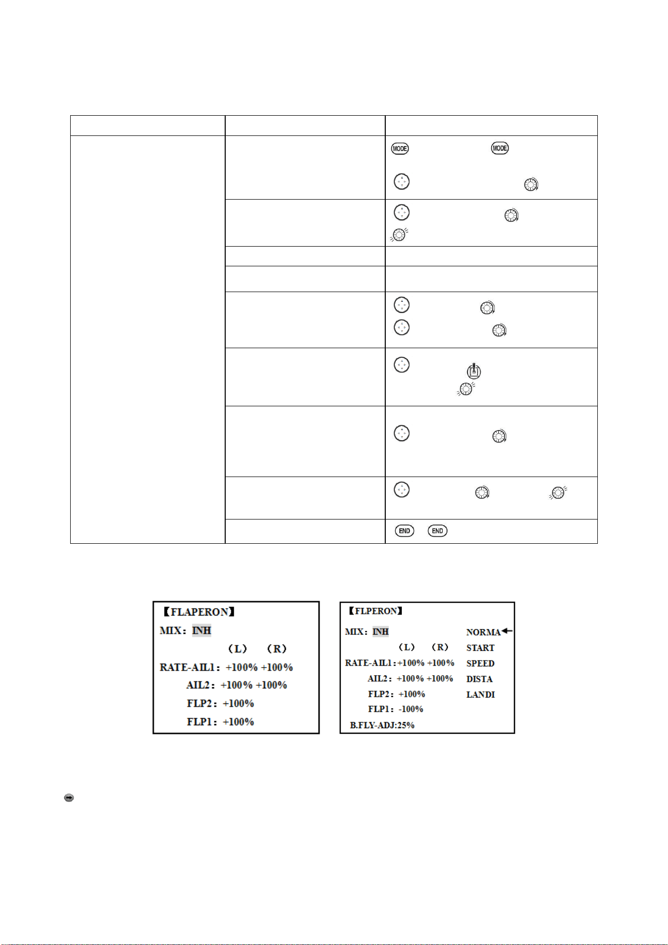
Radiolink Electronic Ltd
www.radiolink.com
41
• Trim: not available in curve mixes.
• Offset: not available in curve mixes.
Goals
Steps
Inputs
Set up a RUDD-ELEV curve
mix on a model that pitches
down severely at full rudder
and not at all with minimal
rudder input, and pitches worse
on right rudder than left:
Point 1: 25%
Point 2: 8%
Point 3: 0%
Point 4: 10%
Point 5: 28%
ON
when SWITCHC is down.
LINK
should be
ON
if model
has twin elevator servos.
Otherwise,
LINK
remains
OFF
.
(Note that point 3 is 0%.
Otherwise, the elevator would
be retrimmed when the mix is
active and no rudder input is
given.)
Open an unused programmable
mix.(Ex: use PROG.MIX7 since
it is already set up for
FLAP-ELEVATOR)
to BASIC menu, again to
ADVANCE
to PROG.MIX PUSH 7,PUSH
Activate the function
to MIX,PUSH, to ON, PUSH
Choose master and slave
channels.
Already RUDD. Already ELEV
Set LINK as needed( Ex: off)
Assign SWITCH and position.
(Ex: change from F to C,Down)
to SW.PUSH. to C,PUSH
to POSI, PUSH. to DOWN
Optional: set switch to
STK-THR to activate mix with
THROTTLE STICK.
to POSI, Throttle Stick to
desired point .
Push 1sec.to set.
Optional: set switch position to
NULL. Make mix active at all
time. Not complete with
STK-THR.
to POSI, PUSH, to NULL
Set desired percent at five stick
points.
to POINT -1 to 25% ,
Repeat for points 2-5.
Close
3.3.3 FLAPERON (ACRO/GLID 1A+1F ):
ACRO GLID
The FLAPERON mixing function uses one servo on each of the two ailerons, and uses them for
both aileron and flap function. For flap effect, the ailerons raise/lower simultaneously. Of course,
aileron function (moving in opposite directions) is also performed.
Note: When changing the polarity of a rate, "change rate dir?" is displayed for a check. Please
set up after pressing DIAL for 1 second and canceling an alarm display. (GLID only)
Once FLAPERON is activated, any time you program CH6 or "flap" (i.e. ELEVATOR mixing), the
radio commands both servos to operate as flaps. The amount of travel available as flaps is
independently adjustable in FLAPERON. A trimming feature is also available (see FLAP-TRIM) to
adjust both neutral positions together for straight-and-level flight or slight increases/decreases of
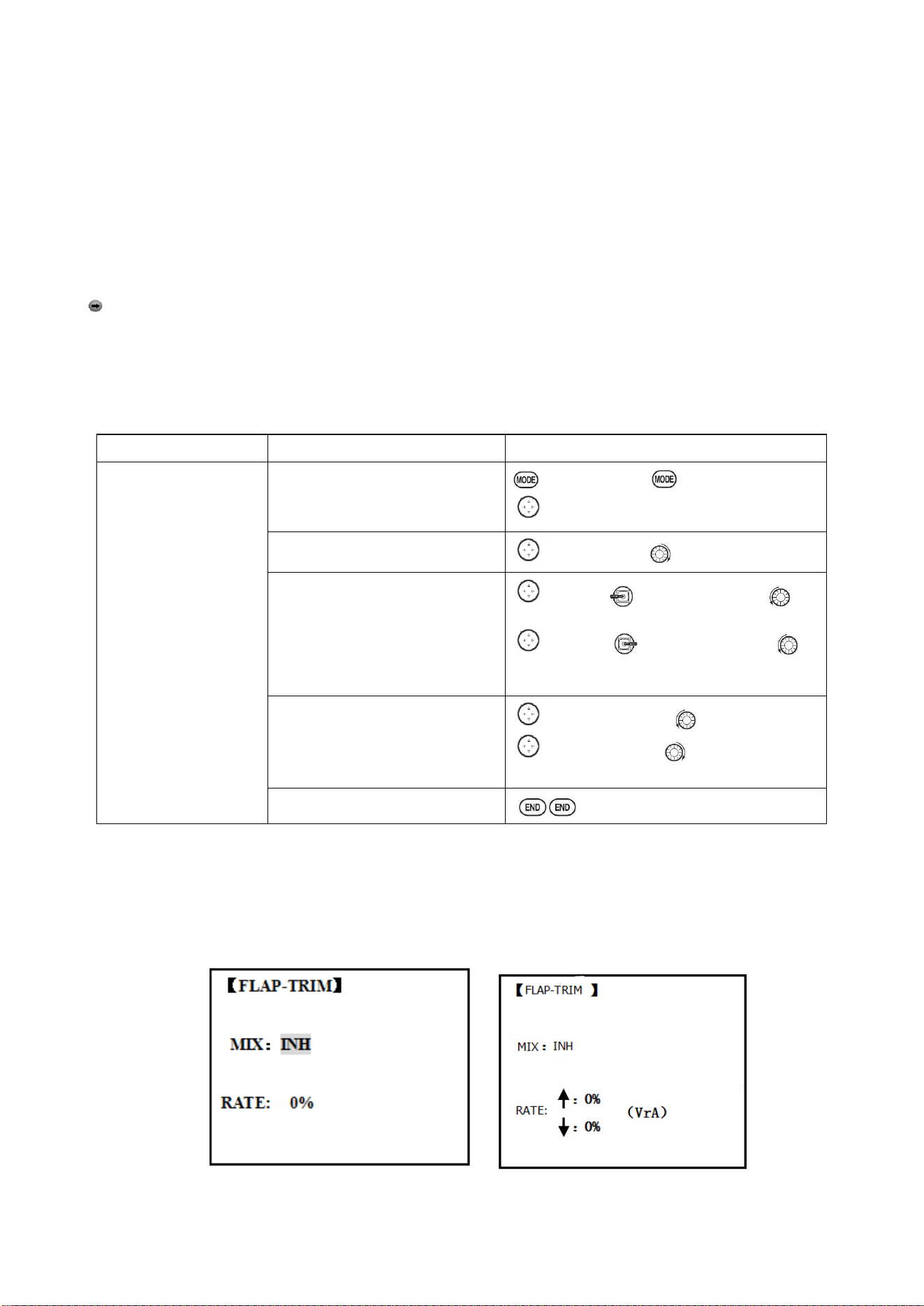
Radiolink Electronic Ltd
www.radiolink.com
42
the flap angle. END POINT and SUB-TRIM both still adjust each servo individually.
Adjustability:
• Each aileron servo up travel can be set separate from its down travel, creating aileron differential.
(See example).
• Each aileron servo's travel when actuated as a flap is separately adjustable.
• AILE-2 can be utilized to use a 5-channel receiver and still have FLAPERON. NOTE: The AILE-2
function only commands the channel 5 servo to operate with the aileron servo as ailerons, and to
obey the primary flap control (travel adjusted in FLAP-TRIM.) It does not provide full flap mix
capability as when using a 6+ channel receiver and channel 6.
• The separate FLAPERON settings for each condition can be set. (GLID)
Note: Activating FLAPERON only makes the ailerons work as ailerons and tells the radio how far
you want them to move as flaps. If you then activate other programming that moves them as flaps.
FLAP-TRIM is the flap-trimming feature that allows the flaps to move in reaction to the channel 6
control. It is meant only for trimming the flaps' center but can also be used as full flap control.
ELEVATOR-FLAP would add elevator mixing into the flap movement from the flap dial after
FLAP-TRIM is activated.
Goals
Steps
Inputs
Activate twin aileron
servos, FLAPERON.
Input 10% less down
travel than up travel
(aileron differential)
within the FLAPERON
programming.(Decrease
right aileron down travel
to 90%,decrease left
aileron down travel to
90%)
Adjust total flap travel
available to 50% of
aileron travel available.
Open the FLAPERON.
to BASIC menu, again to ADVANCE
to FLAPERON .PUSH.
Activate the function.
to MIX. PUSH. to ACT
Optional: adjust the up/down
travel for 2 servos.(Ex:90% down)
to AILE1 AILERON STICK. to
90%
to AILE2, AILERON STICK, to
90%
Optional: Use as total flap control.
Resign CH6 is primary control in
AUX-CH to desired flap
control.(Ex: right slider)
to FLAP2 PUSH, to +50%
to FLAP1.PUSH, to -50%
Close
* If you receive an error message that OTHER WING MIXING IS ON, you must deactivate AIL-DIFF
or ELEVON.
3.3.4 FLAP-TRIM
Using FLAP-TRIM to adjust FLAPERON (ACRO/GLID)
ACRO GLID
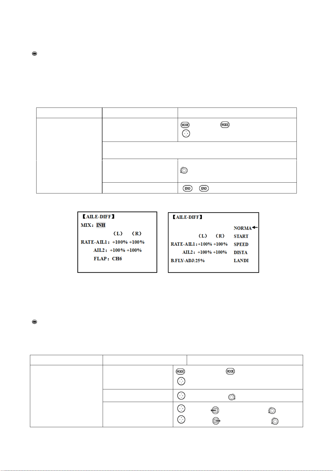
Radiolink Electronic Ltd
www.radiolink.com
43
FLAP-TRIM assigns the primary FLAPERON control [defaults to VR(A)] to allow trimming in flight of
the flap action of FLAPERON.
Note: Even if FLAP-TRIM is made active with AIL-DIFF, it will not have any effect. The ONLY
function that allows control of the ailerons as flaps in the AIL-DIFF configuration is AIRBRAKE. Most
modelers use AIRBRAKE, or programmable mixes, to move the flaps to a specified position via
movement of a switch.
FLAP-TRIM may also be used as the primary flap control in flight. By doing so, you can assign CH6
to a 3-position switch, with a "SPOILERON", neutral, and "FLAPERON" position, and even adjust
the percentage traveled as FLAPERON/SPOILERON by changing the Flap Trim travel.
Goals
Steps
Inputs
Add FLAP-TRIM to
allow the model’s ailerons
to be trimmed together as
flaps at any time during
the flight, with a
maximum travel of 5% of
the total flap travel set in
FLAPERON.
Open FLAP-TRIM function
to BASIC again to ADVANCE
to FLAP-TRIM.PUSH.
The function is automatically activate with FLAPERON; however the default
travel is 0.
Adjust the travel available to
the FLAPERON when turning
the CH6 dial.
to 5%
Close
3.3.5 AILE DIFF (ACRO/ GLID 2A+1F/ GLID 2A+2F)
ACRO GLID (2A+1F)/GLID (2A+2F)
Aileron differential is primarily used on 3 or 4-servo wings, with one servo operating inboard flap on
CH6 or CH5 & CH6, and AILE-DIFF controlling proper aileron operation of 2 aileron servos, plugged
into CH1 and CH7. The ailerons can not be moved like flaps when using AILE-DIFF, except if using
AIRBRAKE. (Note that even if you make FLAP-TRIM active while using AILE-DIFF, it will not have
any effect. ONLY AIRBRAKE controls the ailerons as flaps in the AILE-DIFF configuration.)
Note: When changing the polarity of a rate in camber-flap, "change rate dir?" is displayed for a
check. Please set up after pressing DIAL for 1 second and canceling an alarm display. (GLID only)
•
FLAP function allows you to set up 1 or 2 servos for flap action.
• The separate AILE-DIFF settings for each condition can be set. (GLID only)
Goals
Steps
Inputs
Activate twin aileron servos
using AILE-DIFF.
Note that the function
defaults to no difference in
down travel vs. up travel. If
you want differential travel,
simply adjust each side. (Ex:
90%)
Open the FLAPERON.
to BASIC menu, again to ADVANCE
to AILE-DIFF .PUSH.
Activate the function.
to MIX,PUSH. to ACT
Optional: adjust the
up/down travel for 2
servos..(Ex:90% down)
to AILE1 AILERON STICK. to 90%
to AILE2, AILERON STICK, to 90%
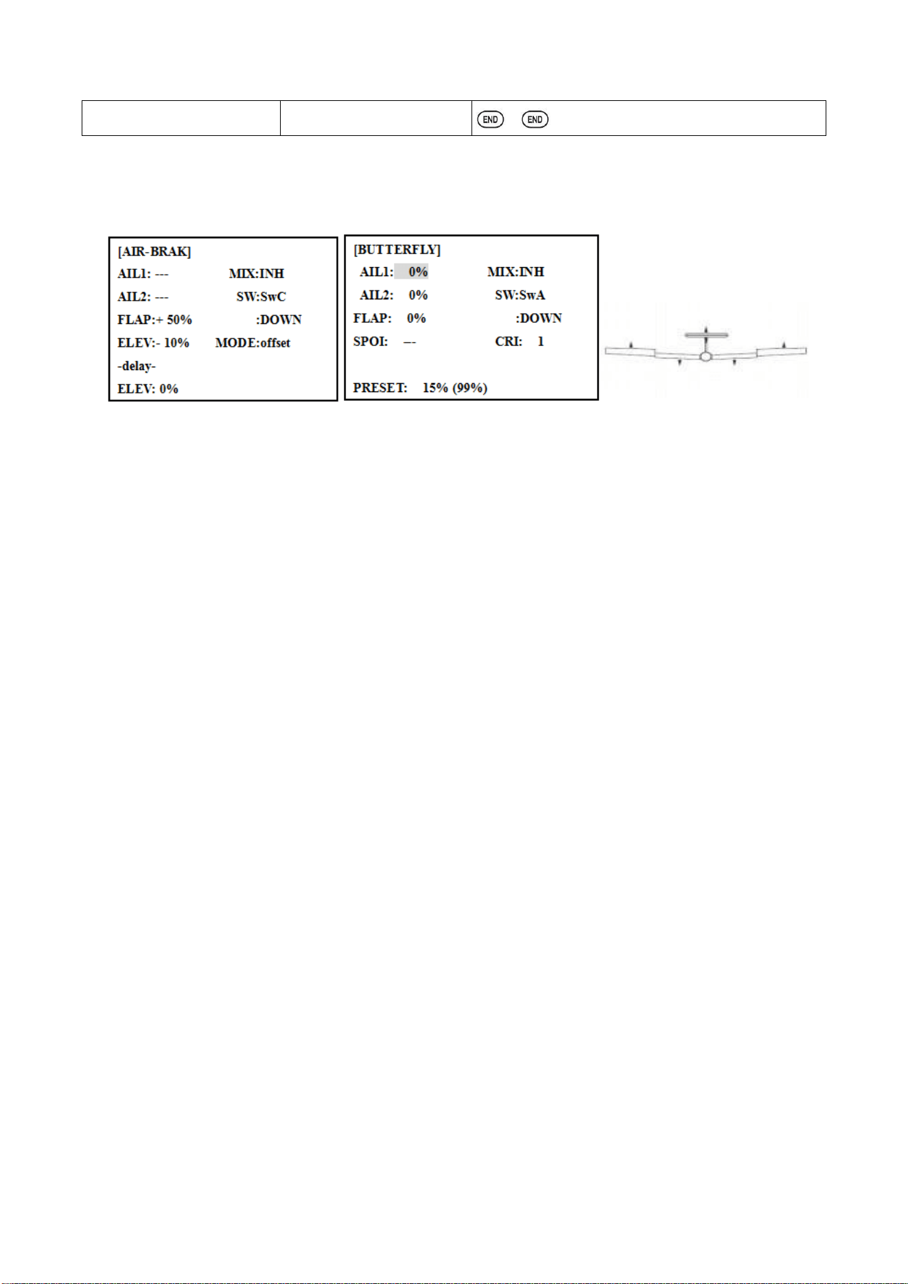
Radiolink Electronic Ltd
www.radiolink.com
44
Close
*If you receive an error message that OTHER WING MIXING IS ON, you must deactivate ELEVON
or FLAPERON.
3.3.6 Air Break (ACRO/ GLID)
ACRO GLID
Like FLAPERON and AILEVATOR, AIRBRAKE is one function that is really made up of a series of
pre-programmed mixes all done for you within the radio. AIRBRAKE (often called "crow" or
BUTTERFLY - see GLID, p. 62 for details) simultaneously moves the flap (if installed), twin ailerons
(if installed) and elevator, and is usually used to make steep descents or to limit increases in
airspeed in dives.
This function is often used even on models without flaps as an easy way to use the FLAPERON and
FLAP-ELEVATOR mixing together.
ADJUSTABILITY:
• Activation: be proportional by moving the THROTTLE STICK, or set positions by flipping the
assigned switch.
• Switch: Mix SWITCH is selectable.
• Also LOGIC SW (Lsw1 to 3) may be assigned.
• Linear(Inversely proportional to THROTTLE STICK): Provides a proportional increase in amount
of AIRBRAKE action as THROTTLE STICK is lowered and assigned switch is on. It provides
gradually more AIRBRAKE as you slow the engine. Includes selectable stick position where
AIRBRAKE begins, gradually increasing to the same setting as the THROTTLE STICK is lowered. If
you would like to have the airbrake be directly proportional to throttle stick, you will
need to reverse the THR-REV function. Note that this changes the throttle stick direction for all
models.
• Offset: Provide AIRBRAKE response immediately upon switch movement, going to a pre-set
travel on each active channel without any means of in-flight adjustment.
• During Airbrake operation, the elevator travel is displayed on the elevator trim display in the
Startup screen.
•Delayed reaction: You can suppress sudden changes in your model's attitude when AIRBRAKE
BUTTERFLY is activated by setting the delay (delay-ELEV) item, to slow down the elevator
response, allowing the flaps/ailerons/elevator to all reach their desired end point together. A setting
of 100% slows the servo to take approximately one second to travel the prescribed distance. (GLID:
B.FLY-ELEV function)
• Adjustable in flight (ACRO): Using the aileron (when AILE-DIFF or FLAPERON is activated) and
elevator trim lever in flight can be set to adjust the aileron and elevator settings in your airbrake
rather than adjusting the model's actual aileron and elevator trim. This allows easy adjustment for
any ballooning while in flight. When the airbrake switch is moved to off the trim is again adjusting
the normal elevator trim.
• Channels controlled: Elevator, twin ailerons and flap may be set independently in AIRBRAKE,
including set to 0 to have no effect.
• If FLAPERON is active, the travel of the ailerons can be independently adjusted for the servos
plugged into CH1 and CH6. The flap choice has no effect on the FLAPERON.
• If AIL-DIFF is active, then CH1 and CH7 may be independently adjusted.
• Normally both ailerons are raised equally in AIRBRAKE, and the elevator motion is set to maintain
trim when the ailerons rise. Different amounts may be set for each aileron to correct for torque
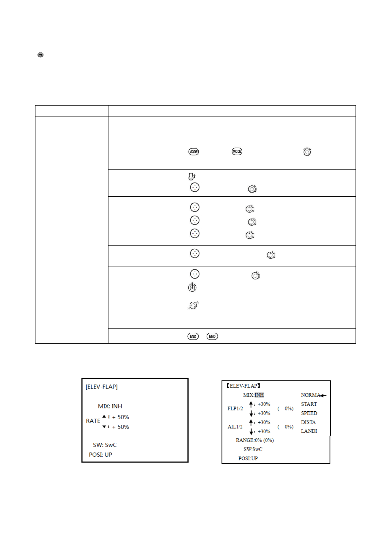
Radiolink Electronic Ltd
www.radiolink.com
45
reactions and other unique characteristics of the model.
Be sure you understand what dropping ailerons will do when in AIRBRAKE BUTTERFLY. Along
with creating an enormous amount of drag (desirable for spot landings), this also creates "wash-in",
a higher angle of attack where the ailerons are, and encourages tip stalling.
If you are using this for aerobatic performance and not "sudden stops", consider raising the ailerons
and dropping the flaps instead as shown in the diagram above.
Goals
Steps
Inputs
Activate AIR-BREAK
on a FLAPERON.
Mode. Adjust the
FLAPERON travel to
75%, with negative
elevator(push) of 25%.
Confirm FLAPERON is
active.
See FLAPERON instructions.
Open AIR-BREAK.
to BASIC . again to ADVANCE to
AIR-BREAK. PUSH.
Activate the function
SW C in up position
to MIX. PUSH to OFF
Adjust the travels as
needed. (Ex: Ailerons
each 75%, Elevator-25%)
to AIL1.PUSH. to +75%, PUSH
to ELEV.PUSH. to -25%, PUSH
to AIL2.PUSH. to +75%, PUSH
Optional: delay the speed
of the elevator servo.
to delay-ELEV. PUSH. to 25%, PUSH
Optional: change the
mixing from full amount
upon switch to
proportional to the
Throttle Stick’s proximity
to idle.
to MODE.PUSH. to Linear(0%), PUSH.
Throttle Stick to desired 0 point.
for 1sec.till beeps
(Display changes if new setting is different from prior
setting)
Close
3.3.7 ELEV-FLAP mixing (ACRO/GLID):
ACRO GLID
ELEV-FLAP mixing is the first pre-programmed mix we'll cover. This mix makes the flaps drop or
rise whenever ELEVATOR STICK is moved. It is most commonly used to make tighter pylon turns
or squarer corners in maneuvers. In most cases, the flaps droop (are lowered) when up elevator is
commanded.
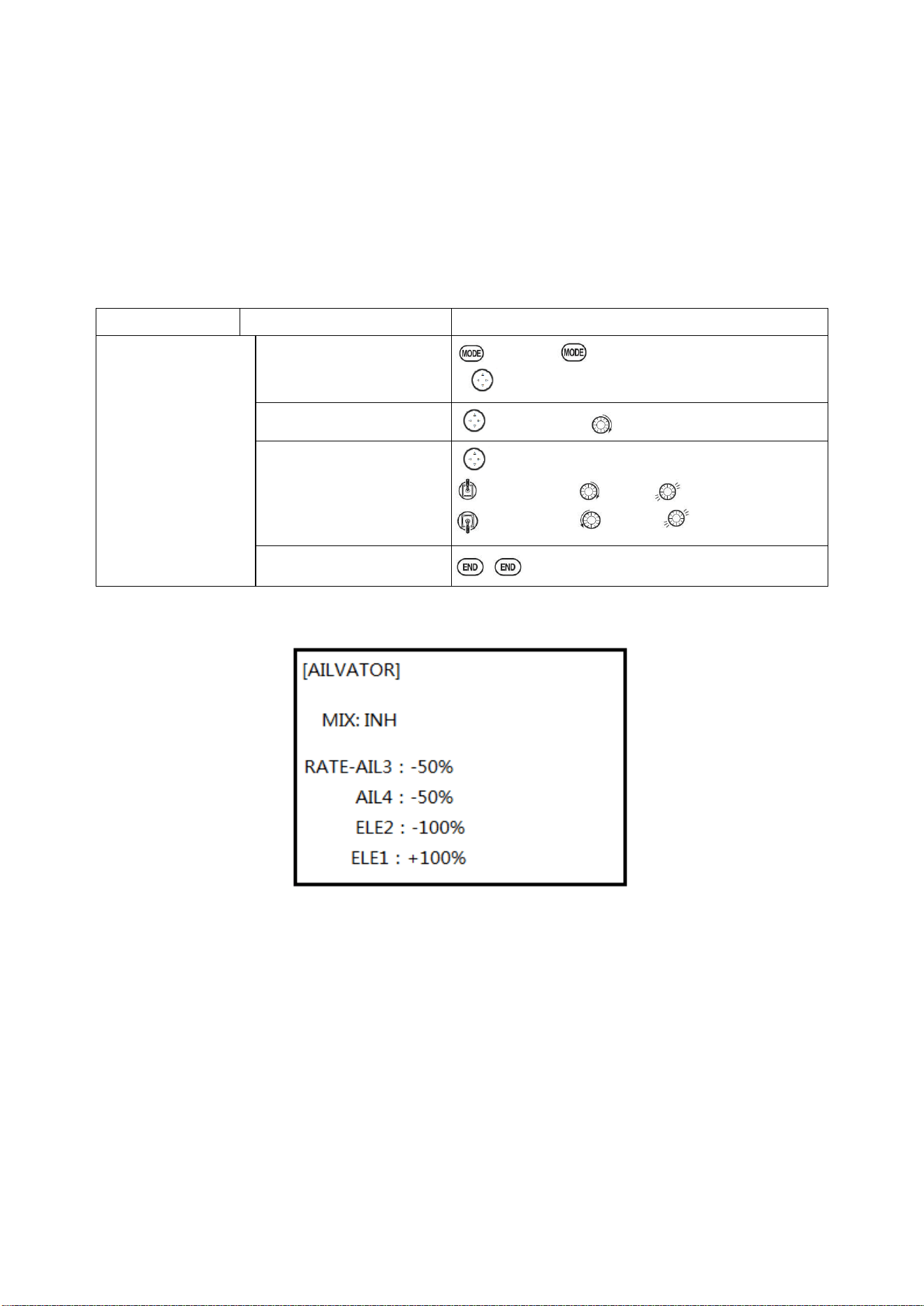
Radiolink Electronic Ltd
www.radiolink.com
46
Adjustability:
• Rate: -100% (full up flap) to +100% (full down flap), with a default of +50% (one-half of the flap
range is achieved when the ELEVATOR STICK is pulled to provide full up elevator.)
• Switch: Fully assignable. Also LOGIC SW (Lsw1 to 3) may be assigned. IF you set it to NULL, the
mix does not work. (ACRO)
•Range (GLID): The range that mixing does not work near neutral of an elevator stick can be set up.
Hold the stick to the desired point (upper or lower side) , then press DIAL and hold one second to
set the range.
• Condition (GLID): The separate ELEV-FLAP settings for each condition can be set.
Goals
Steps
Inputs
Activate ELEV-FLAP
mixing. Adjust flap
travel to 0% flaps with
negative elevator
(push) and 45%flaps
with positive elevator.
Open ELEV-FLAP
to BASIC . again to ADVANCE
to ELEV-FLAP. PUSH.
Activate the function
to MIX,PUSH. to ON.PUSH
Adjust the travels as
needed. (Ex:0%, to45%)
to RATE.
Elevator Stick to 0%,
Elevator Stick
to + 45%,
Close
3.3.8 Dual Elevator Servos (with a rudder) (AILEVATOR) (ACRO):
Many models use two elevator servos, plugged in separate receiver channels. (Flying wings without
a separate aileron control use ELEVON. V-shaped tail models use V-TAIL,
ADVANTAGE:
•Ability to adjust each servo's center and end points for perfectly matched travel.
• Ease of assembly, not requiring torque rods for a single servo to drive 2 surfaces.
• Elevators acting also as ailerons for extreme stunt flying or more realistic jet flying (optional).
• Redundancy, for example in case of a servo failure or mid-air collision.
ADJUSTABILITY:
• CH2 and CH8 only. (With programmable mixing, could utilize CH5 as the 2nd elevator servo.
THROTTLE-NEEDLE uses CH8 and cannot be active simultaneously).
• Direction of each servo's travel may be reversed in REVERSE or the set percentages may be
reversed here.
• Elevator travels independently adjustable (both directions and percent).
•Optional action as ailerons (defaults to 50% response). This response cannot be activated/
deactivated in flight. Setting AIL1 and 2 to 0 disables this feature.
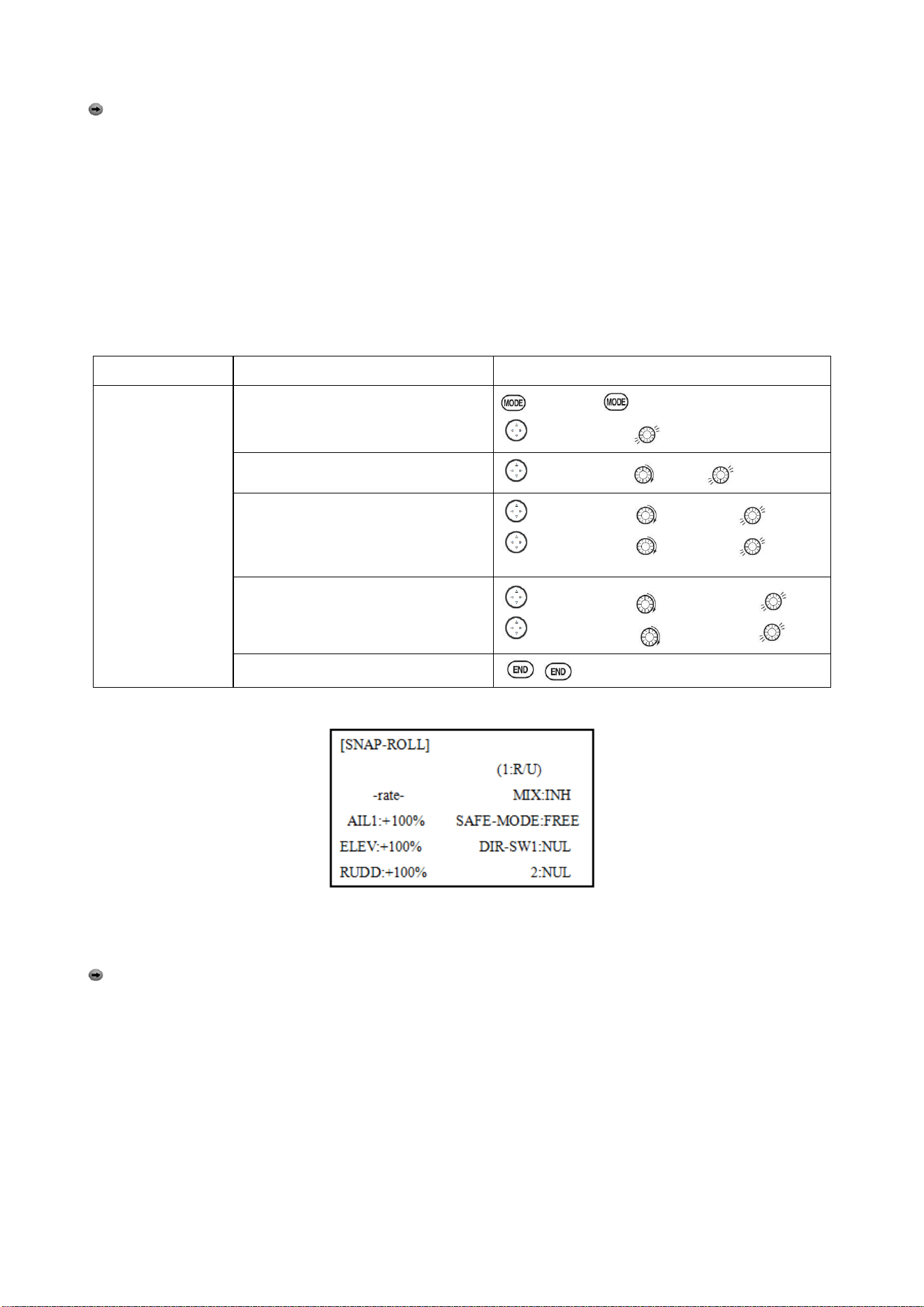
Radiolink Electronic Ltd
www.radiolink.com
47
Note: if you want this, but on/off with a switch, set AIL1 and 2 to 0 here, and use 2 mixes.
AIL-to-AUX2 (link/trim off, assign a switch), get aileron action from the elevator servos when the
assigned switch is on.
The AILEVATOR mixing function uses one servo on each of the two elevators, and combines the
elevator function with the aileron function (unless aileron travel is set to 0). For aileron effect, the
elevators are raised and lowered opposite of one another in conjunction with the ailerons.’
Once AILEVATOR is activated, unless you zero out the aileron figures (see below), any time you
move your ailerons or any programming moves your ailerons (i.e. RUDDER-AILERON mixing), the
radio automatically commands both elevator servos to also operate as ailerons. To deactivate this
action, simply set the 2 aileron travel settings to 0 in the AILEVATOR function. This way the
elevators will work only as elevators.
Goals
Steps
Inputs
Activate twin
elevator servos.
Deactivate the
elevator-acting
–as-ailerons portion
of this function.
Note: depending
upon your model’s
geometry, may need
to reverse one servo
or set a negative
percentage here.
Open the AILEVATOR
to BASIC . again to ADVANCE
to AILVATOR,
Activate the function.
to MIX,PUSH. to ACT.
Optional: adjust up/down travel when
operating as ailerons. (Ex:0)
to AIL3,PUSH. to 0%, press
to AIL4,PUSH. to 0%, press
Optional: adjust total elevator travel
of each servo. (Ex: right servo
elevator travel to 98%,left to 96%)
to ELE2.PUSH to 98%, press
to ELE1.PUSH. to 96%, press
Close
3.3.9 Snap Rolls (ACRO)
This function allows you to execute snap rolls by flipping a switch, providing the same input every
time. It also removes the need to change dual rates on the 3 channels prior to performing a snap, as
SNAP-ROLL always takes the servos to the same position, regardless of dual rates, inputs held
during the snap, etc.
Note: Every MULTIROTOR snaps differently due to its C.G., control throws, moments, etc. Some
models snap without aileron; others snap on elevator alone. Most models snap most precisely with
a combination of all 3 surfaces. Additionally, rate of speed and acceleration when using the snap
switch will affect how the model snaps. For information using gyros with airplanes for cleaner
precision maneuvers, such as snaps and spins without over rotation.
ADJUSTABILITY:
• Travel: Adjust the amount of elevator, aileron and rudder travel automatically applied.
• Range: -120 to +120 on all 3 channels. Default is 100% of range of all 3 channels.
• Directions: Up to 4 separate snaps is fully adjustable regarding travels and direction on each of the
3 channels.
Note: for simplicity, the radio refers to snaps that use “UP” or positive elevator as “U” or “UP” snaps.
This is more commonly referred to as a positive or inside snap. “D” or “DOWN” snaps are more
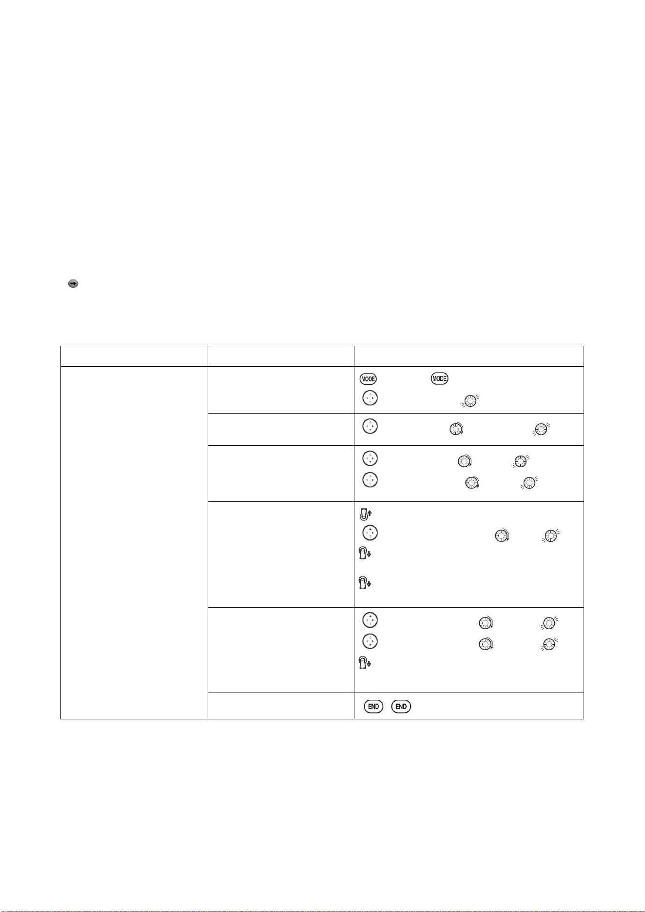
Radiolink Electronic Ltd
www.radiolink.com
48
commonly referred to as negative or outside snaps.
• R/U = Right positive R/D = Right negative L/U = Left positive L/D = Left negative snap roll.
• Assignment of the 2 switches (DIR-SW1/2) to change snap directions is fully adjustable and
optional. If you wish to have only one snap, leave the switches as NULL. (If assigned,
SW1=up/down, SW2=left/right)
• Safety Switch (SAFE-MOD): a safety may be set up on your landing gear SWITCH, preventing
accidental snap rolls while the landing gear is down. The safety switch is turned on and off with the
landing gear SWITCH.
• ON: the safety mechanism is activated when the landing gear SWITCH is in the same position as
at the time this feature is changed to ON. Snap rolls will not be commanded even if the snap roll
SWITCH is turned on with the gear SWITCH in this position. When the landing gear SWITCH is
moved to the opposite position, snap rolls may be commanded.
• OFF: Activate the safety mechanism in the opposite position from the ON function.
• FREE: The safety mechanism is completely turned off. Snaps can be commanded regardless of
the gear SWITCH POSITION.
Note: The location of the safety switch always follows channel 5. If channel 5 is reassigned to
switch C, for example, switch C is now the safety. If channel 5 is null or used as the second aileron
servo, the safety function will not be available.
• Trainer Safety: SNAP-ROLL is automatically disabled when the trainer function is activated.
Goals
Steps
Inputs
Activate SNAP-ROLL. Adjust
elevator travel to 55%, rudder
travel to 120% in the right/up
snap. Activate SAFE-MODE
so snaps can not be performed
when gear is down.
Adjust rudder travel in the
left/down snap to 105%.
(Note:using negative percents
can change any of the 4snap
directions. For example.
change snap 1to ‘down’ by
changing the elevator percent
to -100%)
Open SNAP-ROLL.
to BASIC . again to ADVANCE
to SNAP-ROLL,
Activate the function
to MIX.PUSH to OFF or ON.
Adjust the travel as needed.
(Ex: elevator to 55%,rudder
to 120%)
to ELEV.PUSH. to 55%
to RUDD.PUSH . to 120%,
Optional: Activate
SAFE-MOD.(Ex: ON when
Sw E or Sw G is down,
meaning snap function is
deactivate when that switch is
in the down position)
E or G to UP position
to SAFE-MODE.PUSH. to ON.
snap switch
NOTE: MIX is OFF.
E or G to DOWN position.
NOTE: MIX is ON.
Optional: Assign switches
up/down and left/right.(Ex:
Change to the left/down snap
and adjust rudder to 105%)
to DIR-SW1.PUSH to SwA
to DIR-SW2.PUSH to SwB,
A down, B down
Repeat steps above to set percentages.
Close
3.3.10 V-Tail (ACRO/ GLID)
V-TAIL mixing is used with v-tail MULTIROTOR so that both elevator and rudder functions are
combined for the two tail surfaces. Both elevator and rudder travel can be adjusted independently
on each surface.
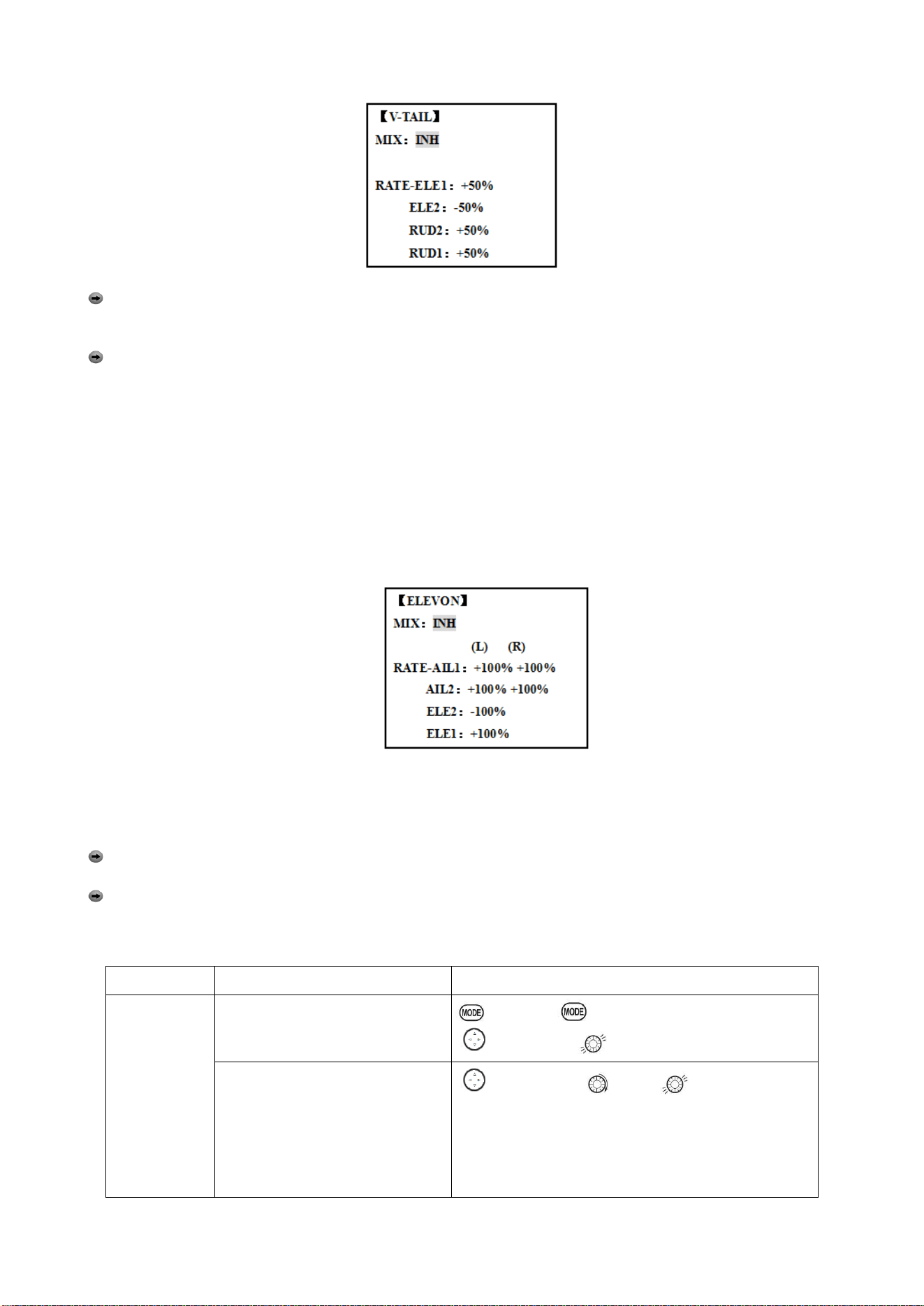
Radiolink Electronic Ltd
www.radiolink.com
49
Note: NOTE: If V-TAIL is active, you cannot activate ELEVON or AILEVATOR functions. If one of
these functions is active, an error message will be displayed and you must deactivate the last
function prior to activating ELEVON.
Note: Be sure to move the elevator and rudder sticks regularly while checking the servo motions.
If a large value of travel is specified, when the sticks are moved at the same time, the controls may
bind or run out of travel. Decrease the travel until no binding occurs.
Adjustability:
• Requires use of CH2 and CH4.
• Independently adjustable travels allow for differences in servo travels.
• Rudder differential is not available. (To create rudder differential, set RUD1 and 2 to 0, then use
two programmable mixes, RUD-ELE and RUD-RUD, setting different percents for up and down.
These are your new rudder travels. Trim and link off, switch assignment null so you can’t
accidentally turn off rudder.
3.3.11 ELEVON
ADJUSTABILITY:
• Requires use of CH1 and CH2.
• Independently adjustable aileron travel allows aileron differential.
• Independently adjustable elevator travel allows for differences in up vs. down travel.
• The separate ELEVON settings for each condition can be set. (GLID only)
Note: When changing the polarity of a rate, "change rate dir?" is displayed for a check. Please
set up after pressing DIAL for 1 second and canceling an alarm display. (GLID only)
Note: Be sure to move the elevator and aileron sticks to full deflection during setup. If large
travels are specified, when the AILERON and ELEVATOR STICKS are moved at the same time the
controls may bind or run out of travel.
Goals
Steps
Inputs
Activate
ELEVON.
Adjust aileron
down travel to
90% of up
travel, creating
aileron
differential.
Open ELEVON
to BASIC . again to ADVANCE
to ELEVON,
Activate the function.
to MIX,PUSH to ACT.
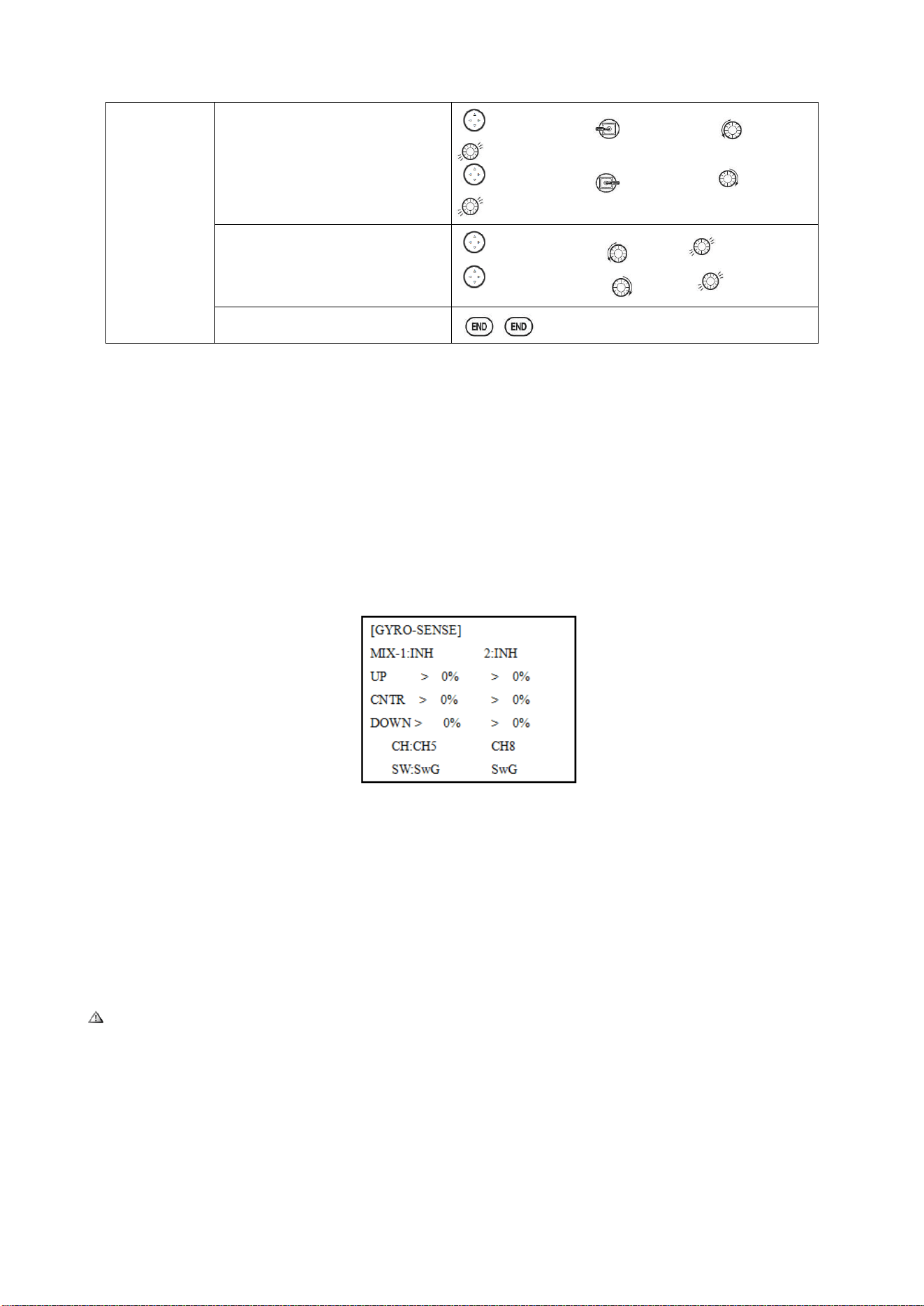
Radiolink Electronic Ltd
www.radiolink.com
50
Optional: adjust up/down travel
separately for the servos as
ailerons.(Ex: down to 90%)
to AIL1.PUSH. Aileron Stick. to 90%
to AIL2.PUSH. Aileron Stick. to 90%
Optional: adjust the elevator travel
of each servo.(Ex: right servos
elev. Travel to 98%, left to 105%.)
to ELE2.PUSH. to 98%.
to ELE1.PUSH.
to 105%
Close
3.3.12 Gyro Sense
The gyros have two operations modes: GY mode and STD mode.
•STD mode: This mode performs general proportional control operation. For instance, it controls the
gyro so that changes are countered when the attitude of the MULTIROTOR is changed by
cross-wind, etc.
•GY mode: This mode performs both proportional and integrated control operation. The difference
between Normal mode and GY mode operation is that where as the Normal mode only counters
changes in attitude, the GY mode returns to the original controlled variable simultaneously with
countering changes in attitude. For example, during knife edge flying, aileron and elevator meeting
rudder is normally necessary, but in the GY mode, meeting rudder is performed automatically by the
gyro.
Adjustability:
• Plug the gyro's sensitivity adjustment to channel 5, 7, or 8 of the receiver. (Selectable)
• Full switch assignable (SWITCH A-H)
• Each rate setting may be set from 0 to NOR100% or AVC100% gain. NOR: GY mode gain. AVC:
STD mode gain
• Larger percentages indicate more gain, or gyro responsiveness.
• MIX-1,2: Two surfaces' sensitivity can be adjusted independently.
GYRO GAIN ADJUSTABILITY:
• When the servo hunts, the gyro gain is too high. Lower the gain until the hunting stops.
• The gyro will display best performance at a gain just before hunting occurs. Perform adjusting by
flying the MULTIROTOR repeatedly.
Precaution:
• When taking off and landing, always switch to the Normal mode. Taking off and landing in the GY
mode is dangerous.
•We recommend that you use the rudder control gyro in the Normal mode. In the GY mode, rudder
operation is necessary when turning because the weather vane effect is lost. Use the gyro in the
Normal mode unless you are an expert in rudder operation.
• And we recommend that you also set to off (0%) mode for safety as follows.
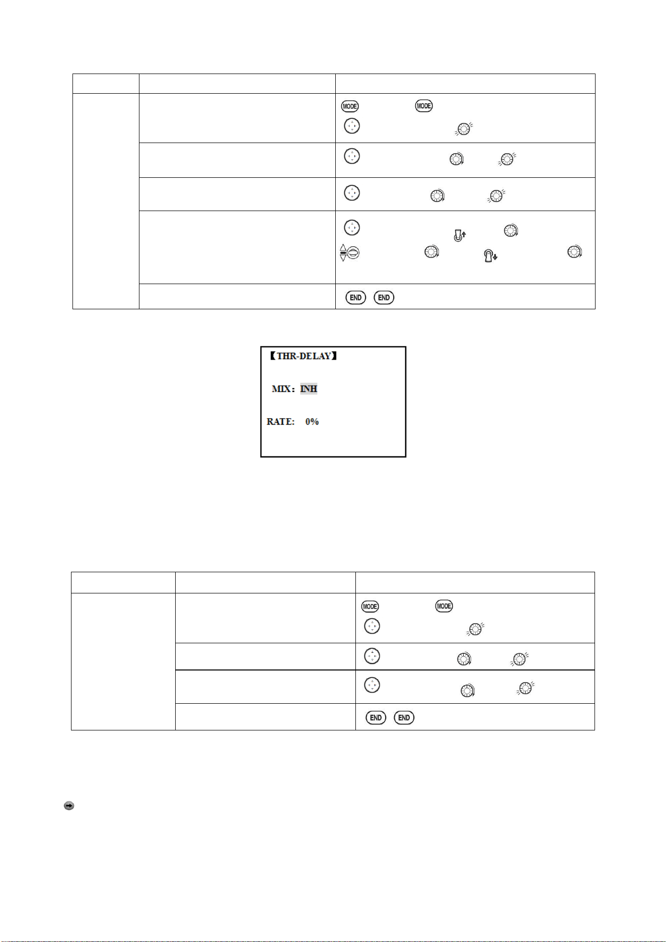
Radiolink Electronic Ltd
www.radiolink.com
51
Goals
Steps
Inputs
Set up a
GYA gyro
setting
(Ex:MIX-1)
Open GYRO-SENSE
to BASIC . again to ADVANCE
to GYRO-SENSE,
Activate the function.
to MIX-1.PUSH to ON.
Optional: change switches assignment.
Ex: select E.
to SW.PUSH. to SwE
Adjust gyro rates as needed.(Ex: UP to
NOR70%,CNTR to 0%[off], DOWN to
AVC70% as starting points.
to gyro rate. Push. E up. to NOR 70%,
E to CNTR, to 0%, E DOWN, to
AVC70%
Close
3.3.13 THR-DELAY (ACRO)
The THR-DELAY function is used to slow the response of the throttle servo to simulate the slow
response of a turbine engine. A 40% delay setting corresponds to about a one-second delay, while
a 100% delay takes about eight seconds to respond. This function may also be used to create a
“slowed servo” on a channel other than throttle. This is accomplished by plugging the desired servo
(Ex: gear doors) into CH3 (THR), throttle into an auxiliary channel such as 8, and then using some
creative mixes.
Goals
Steps
Inputs
Activate
THR-DELAY for a
ducted-fan replica of
a turbine-powered
MULTIROTOR.
Slow the servo
response by one
second.
Open THR-DELAY
to BASIC . again to ADVANCE
to THR-DELAY,
Activate the function.
to MIX.PUSH. to ACT.
Adjust the RATE to match the
desired servo speed.(Ex:40%)
to RATE.PUSH to 40%
Close
3.3.14 THR CURVE (ACRO)
This function adjusts the throttle operation curve for optimum the engine speed to throttle stick
movement.
Note: If the throttle EXP function is activated, you can not use THR-CURVE function
simultaneously.
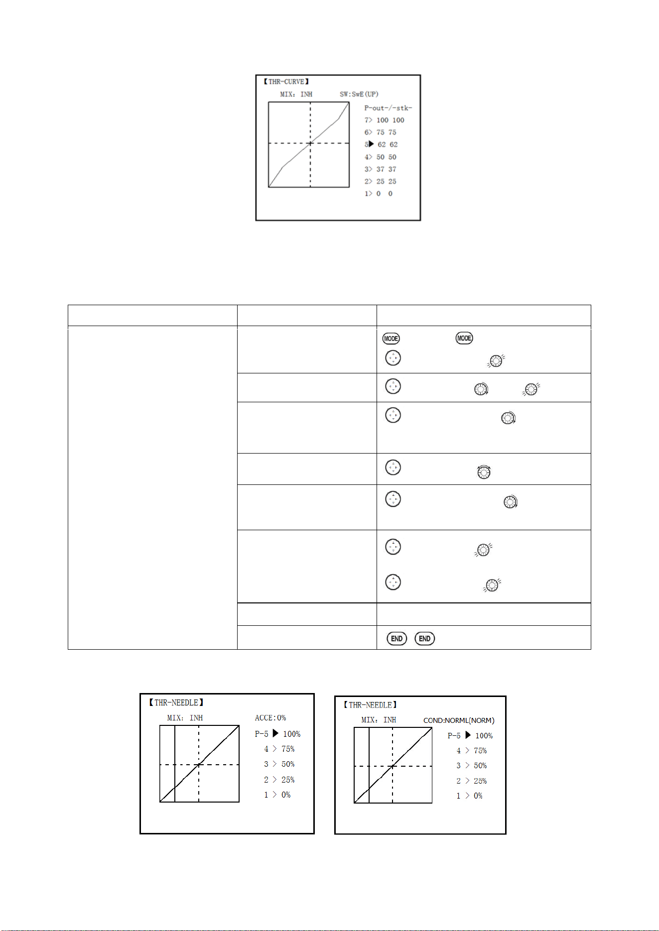
Radiolink Electronic Ltd
www.radiolink.com
52
Adjustability:
• Separate curves for each switch position are available.
• Moving and deleting the curve point: The curve point (-STK-) can be moved to the left or right by
turning the DIAL (up to 2% in front of the adjoining point) and deleted/returned by pressing the DIAL
for one second alternately.
Goals
Steps
Inputs
Base point: Adjust base point of
throttle curve until engine idles
reliably.
-Out-:output,servo position.
-STK-: curve point, stick position.
Open THR-CURVE
to BASIC . again to ADVANCE
to THE-CURVE,
Activate the function.
to MIX.PUSH to ON.
Adjust the 1
st
point
to P1(-out-).PUSH to desired
servo position
Optional: assign the switch.
to SW.PUSH, to desired switch.
Optional: Move the curve
point.(Ex: point 3)
to P 3 (-stk-),PUSH to desired
curve point to move to left or right.
Optional: delete the curve
point. And return the curve
point.(Ex: point 3)
to P 3 (-stk-). for 1sec.to delete
the curve point.
to P 3 (-stk-), for 1sec.to return
Adjust the next point.
Repeat as needed.
Close
3.3.15 THROTTLE-NEEDLE mixing (ACRO/ HELI):
ACRO HELI
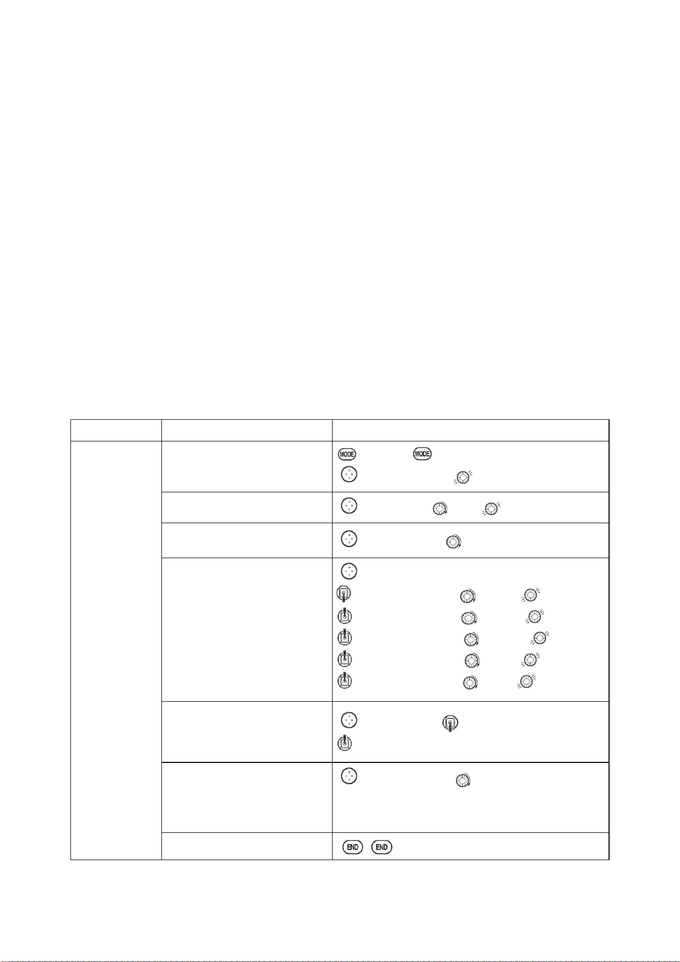
Radiolink Electronic Ltd
www.radiolink.com
53
THROTTLE-NEEDLE is a pre-programmed mix that automatically moves an in-flight mixture servo
(CH8) in response to the THROTTLE STICK inputs for perfect engine turning at all throttle settings.
This function is particularly popular with contest pilots who fly in a large variety of locations, needing
regular engine tuning adjustments, and requiring perfect engine response at all times and in all
maneuvers. Also popular to minimize flooding at idle of inverted engine installations or installations
with a high tank position. Not needed for fuel injection engines, which do this automatically.
ADJUSTABILITY:
• Five-point curve allows adjustment of engine mixture at varied throttle settings.
• The in-flight mixture servo must connect to receiver CH8.
• In-flight mixture servo may also be used as a second servo for tuning a twin.
• Throttle cut feature also moves the in flight needle servo.
• The CH8 knob adjusts the high throttle mixture (may be deactivated. see AUX-CH).
• Because both use CH8, this function cannot be used simultaneously with AILEVATOR.
• An acceleration (ACCE) function (ACRO only) helps the engine compensate for sudden, large
amounts of throttle input by making the mixture suddenly richer, then easing it back to the proper
adjustment for that throttle setting. This function requires some adjustment to best fit your engine
and your flying style. Adjust engine's response until no hesitation occurs on rapid throttle input.
• Separate curves are available (HELI only) for normal, idle-ups 1 and 2 combined, and idle-up 3.
Immediately below MIX the radio displays the curve you are editing; ex: >NORML; and then which
condition is currently active by your switches ex: (ID1/2). Note that you can edit the mix for a
different condition without being in that condition, to allow editing without having to shut off the
helicopter’s engine every time. Be sure you are editing the proper curve by checking the name after
the > and not the one in parentheses.
Goals
Steps
Inputs
Activate
THROTTLE-
NEEDLE
mixing.
Adjusting the
points as
follows: to
resolve a slight
lean midrange
problem:
1:40%
2:45%
3:65%
4:55%
5:40%
Open THROTTLE-NEEDLE
to BASIC . again to ADVANCE
to THR-NEEDLE,
Activate the function.
to MIX.PUSH to ON.
HELI only. Select the condition
to edit.
to COND.PUSH. as needed.
Adjust the travels as needed to
match your engine by slowly
moving the stick to each 5 points,
then adjusting the percentage at
that point until the engine is
properly tuned.
to PIONT.
Throttle Stick to P 1, to 40%,
Throttle Stick to P 2, to 45%,
Throttle Stick to P 3, to 65%,
Throttle Stick to P 4 , to 55% ,
Throttle Stick to P 5, to 40%,
ACRO only . Optional: increase
mixture when throttle is applied
rapidly-ACCE.(see above for
details)
to ACCE. Push Throttle Stick to idle
Throttle Stick to full open quickly.
Heli only: set curves for another
conditions.
to condition name to next condition name to
edit.
Repeat above steps as needed.
Close
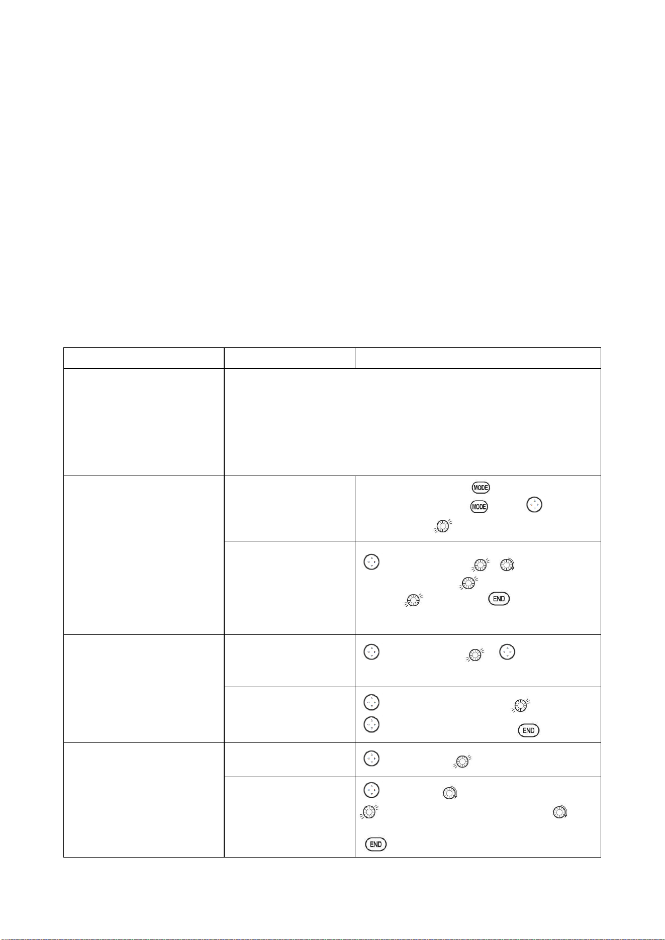
Radiolink Electronic Ltd
www.radiolink.com
54
PART 4 GLIDER MODEL FUNCTIONS
Please note that nearly all of the BASIC menu functions are the same for airplane (ACRO setup),
sailplane (GLID 1A+1F/ 2A+1F/ 2A+2F setups), and helicopter (HELI setups). The features that are
identical refer back to the ACRO chapter. The glider BASIC menu includes MOTOR CUT and does
not include IDLE-DOWN or THR-CUT.
○
→
Note: in all cases where ACRO programming labels channel 3 as throttle, GLID programming
labels channel 3 as ARB (airbrake), since airbrakes are normally operated on channel 3 in gliders.
This includes STK-THR reading STK-ARB.
4.1 SET BASIC MENU OF GLID
This guideline is intended to help you get acquainted with the radio, to give you a jump start on
using your new radio, and to give you some ideas and direction in how to do with this powerful
system.
Goals
Steps
Inputs
Prepare your airplane.
Install all servos, switches, receiver per your model’s instructions. Turn on
transmitter then receiver; adjust all linkages so surfaces are nearly centered.
Mechanically adjust all linkages to get as close as possible to proper control
throws and minimize binding prior to radio set up.
Check servo direction and throws.
Make notes now of what you will need to change during programming.
Select the proper MODEL
TYPE for your model. (Ex:
GLID 1A+1F)
[NOTE: This is one of several
functions that require
confirmation to make a change.
Only critical changes such as a
MODEL RESET require
additional key strokes to accept
the change.]
In the BASIC menu, open
PARAMETER submenu.
Turn on the transmitter. for 1 sec. to
BASIC.(If ADVANCE again.) to choose
PARAMETER.
Choose proper MODEL
TYPE. Ex: GLID
(1A+1F).
Confirm the change.
Close submenu.
to MODEL TYPE , to
GLID(1A+1F), press for 1 sec. Are you sure?
Displays.
to confirm.
Return to BASIC
menu.
Name the model
Note that you do not need to
do anything to ‘save’ or store
this data.
In BASIC menu open the
MODE SEL submenu.
to MODEL SEL. , to NAME.(1
st
character of model’s name is highlighted).
Input airplane name.
Close the submenu.
to change the 1
st
character. to confirm.
to next character and repeat. to return.
REVERSE servos as needed for
proper control operation.
In the BASIC menu, open
REVERSE.
to REVERSE.
Choose desired servo and
reverse its direction of
travel.
(Ex: reverse rudder
servo.)
to 4:RUDD, REV is highlighted. Press
for 1 sec. ‘Are you sure?’ Displays. to
confirm.
To BASIC menu.
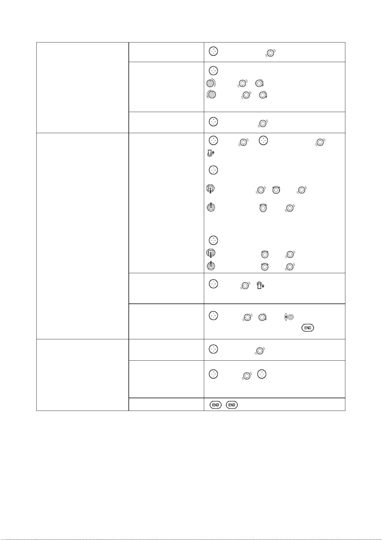
Radiolink Electronic Ltd
www.radiolink.com
55
Adjust travels as needed to
match model’s recommended
throws (usually listed as high
rates).
In BASIC menu choose
END POINT.
to END POINT.
Adjust the servos’ end
points. (Ex: flap servo).
Close the function.
to FLAP
VR(A). , to desired travel.
VR(A). , to desired travel.
Repeat as needed.
Choose D/R,EXP
to D/R,EXP
Set up dual/triple rates and
exponential (D/R, EXP).
(Note that in the middle of the
left side of the screen is the
name of the channel and the
SWITCH position you are
adjusting. Two or even three
rates maybe set per channel by
simply choosing the desired
SWITCH and programming
percentages with the SWITCH in
each of its 2/3 position.)
Choose the desired
control, and set the first
(Ex: high) rate throws and
exponential.
to CH , to CH2(ELEV).
A to UP position. Screen reads ELEV [UP]
to D/R
Elevator Stick. , to set .
Elevator Stick. to set.
(Normally the same for both direction)
to EXP
Elevator Stick to set
Elevator Stick to set
Set the second (Ex: low)
rate throws and
exponential.
to D/R , A to down position. Repeat
above to set low rate.
Optional: change dual
rate SWITCH assignment.
Ex: elevator to SWITCH
G with 3 positions.
to SW , to G, G to center.
Repeat steps above to set 3rd rate.
Move flap control from the (VR
(A)) dial to the left slider.
[VR(D)](AUX-CH) .
In the BASIC menu, open
AUX-CH.
to AUX-CH
Choose CH5. Change
primary control to VR(D).
Change other channels as
needed.
to CH5 , to VR(D)。
Repeat steps above to set other channels.
Close
4.2 SET GLID TYPE
TYPE: (GLID 1A+1F), GLID (2A+1F), GLID (2A+2F)
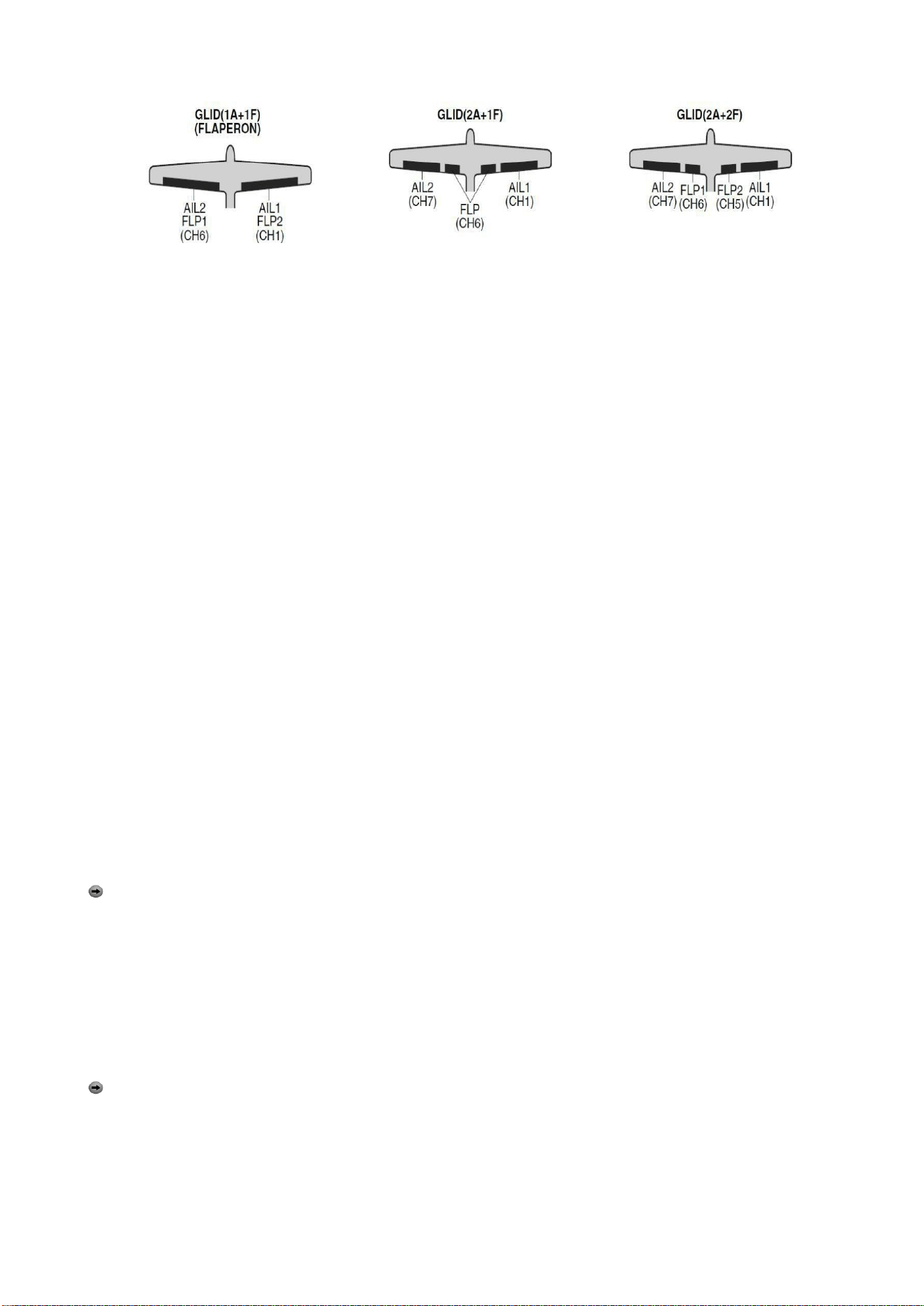
Radiolink Electronic Ltd
www.radiolink.com
56
Before doing anything else to set up a glider or sailplane, first you must decide which MODEL TYPE
best fits your MULTIROTOR.
• GLID(1A+1F): The GLID (1A+1F) MODEL TYPE is intended for sailplanes with one or two aileron
servos (or none), and a single flap servo (or two connected with a y-connector). This TYPE is meant
to be a very simplistic version to set up a basic glider without a lot of added features. Additional
flight condition is available.
• GLID (2A+1F): The GLID (2A+1F) MODEL TYPE is intended for sailplanes with dual aileron
servos and a single flap servo (or two connected with a y-connector). Additional flight conditions are
available. These flight conditions contain different offset trims and aileron differentials to make the
sailplane perform certain maneuvers more easily.
• GLID (2A+2F): The GLID (2A+2F) MODEL TYPE supports dual flap servos that can also act as
ailerons, creating full-span ailerons and flap. Additional flight conditions are available. These flight
conditions contain different offset trims and aileron differentials to make the sailplane perform
certain maneuvers more easily.
4.3 GLID ADVANCE MENU
MIXES:
• Linear Programmable mixes (PROG.MIX1-4): Fully assignable programmable mixed with a linear
response.
• Curved Programmable mixes (PROG.MIX5-8): Fully assignable programmable mixed with a
curved response.
• ELEV-FLAP pre-programmed mix creates elevator movement from the inboard flaps as well as
elevators.
• BUTTERFLY: Often called crow, BUTTERFLY is the glider version of AIRBRAKE. (BUTTERFLY
does not have the option to activate it solely from a switch, and its activation switch. It always
provides progressively more BUTTERFLY as the CHANNEL 3 (THROTTLE) STICK is lowered, or
raised if used THR-REV) See AIRBRAKE.
• CAMBER-MIXAILE-FLAP: This pre-programmed mix is used to create full span flap/aileron
action on a glider with 4 wing servos. This changes the camber over the entire wing, which
produces less drag than just dropping the flaps by themselves.
Note: When you have ELEV-FLAP mixing also, the trailing edge droops with the elevators,
increasing pitch response.
• FLAPERON (GLID 1A+1F only): 2 aileron servos operate in opposite directions as ailerons and
same direction as flaps.
• CAMBER FLAP: Provides camber movement or trimming of flaps. For sailplanes, this function is
also used as wing camber. The amount depends on the model but usually a small amount (less
then 10%) is preferred, since too much camber produces excess drag. Don't use more than about
1/16" travel up or down for glider camber. Some airfoils, such as the RG15, should be flown with NO
reflex/camber. Be sure to consult your model's manual for guidelines.
Note: even though you may make CAMBER FLAP active while using AILE-DIFF, it will not have
any effect. The ONLY function that allows control of the ailerons as flaps in the AILE-DIFF
configuration is airbrake/ butterfly
• ELEVON: for flying wings
• V-TAIL: For models with 2 servos operate together to create roll and pitch control.
• AILEVATOR: Not available in GLID model types.
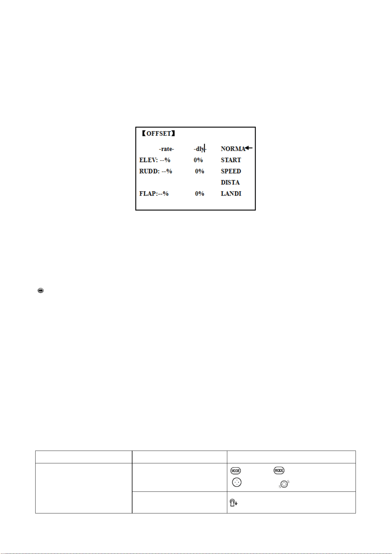
Radiolink Electronic Ltd
www.radiolink.com
57
4.3.1
AILE DIFF (FIND IN ACRO FUNCTION MENU 3.3.5)
4.3.2 FLAPERON (GLID 1A+1F, FIND IN ACRO FUNCTION MENU 3.3.3)
4.3.3 V-TAIL (FIND IN ACRO FUNCTION MENU 3.3.10)
4.3.4 OFFSET (GLID 2A+2F):
Additional flight conditions are available specifically for sailplanes.
These additional flight conditions contain different offset trims to make the sailplane perform certain
maneuvers more easily. Aileron differential functions may be set to provide separate rates per
condition selected.
Prior to setting up OFFSET, you must active the conditions and assign the switches in the
CONDITION/FUNCTION.
Unnecessary fuselage motion is generated when there are sudden changes in the servo position
and variations in the operating time between channels can be suppressed by using the delay
function.
Note: The same delay amount for elevator and rudder is recommended when using V-tail
function.
The AT10II provides 5 additional setups along with the normal flight condition. (NORMAL,
START, SPEED, DISTANCE and LANDING) These offset trims have same setting abilities
basically except the switch and dial assignment. For an example of trim settings, please see the
following:
ADJUSTABILITY:
• Separate adjustments for each aileron, elevator, rudder and flap servo, for each condition.
• SWITCH G (AT10) or E (AT10) is programmed for NORMAL, START, and SPEED trims. SWITCH
C is programmed for DISTANCE and LANDING trims. These switch/position assignment is
adjustable. (CONDITION/FUNCTION)
• TRIM item (Digital trim operation mode):
NORM: normal trim operation mode.
MIX: offset rate trim operation mode while mixing is on.
• Optional assignable knob (CAMBER MIX) to allow trimming in flight of the aileron and flap action
of each flight condition.
• During OFFSET operation, the aileron and elevator travels are displayed on each trim display in
the Startup screen.
Goals
Steps
Inputs
Set up a START to gain
maximum possible lift on launch.
Each Aileron: 50%. Each Flap:
100%.
Elevator: -5% to compensate.
Open OFFSET function
to BASIC . again to ADVANCE
to OFFSET,
Switch to the START condition.
G or E from NORMA to START
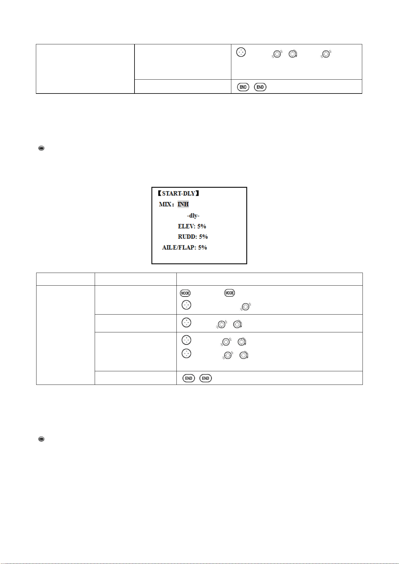
Radiolink Electronic Ltd
www.radiolink.com
58
SWITCH (AT10II=G,
AT10II=E.)
Note: switch is assignable.
(CONDITION)
KNOB(null)
Note: knob is assignable.
(CAMBER MIX)
Set the rates. (Ex: AIL 50%,
FLP 100%, ELEV -5 %.)
to AIL , to 50%,
Repeat for FLP and ELEV.
Close
4.3.5 START DELAY (GLID 1A+1F only):
START DELAY automatically switch the offset trims (OFFSET) from the START condition's trims to
the normal condition’s trims after proceeding the delay time (max.10sec.) which is set by the -DLY-
item when activating the START condition. (It is convenient for hand launch glider.)
Note: The same delay amount for elevator and rudder is recommended when using V-tail
function.
ADJUSTABILITY:
• Delay time (-DLY-) range of 0 to 100%. The delay time is 10 second at 100%.
Goals
Steps
Inputs
Ex: delay time=5
second.
Open ADVANCE menu,
then open START DELAY.
to BASIC . again to ADVANCE
to START-DLY,
Activate the function
to MIX , to OFF or ON
Set the delay time.
(Ex:50% each surface)
to ELEV , to 50%
to RUDD , to 50%
Repeat as needed.
Close
4.3.6 CHAMBER-FLP
CAMBER FLAP assigns the primary flap control [defaults to VR (A)] to allow trimming in flight of the
flap action. The up and down travel of each flap (camber flaps: FLP1/2) can be adjusted
independently. Also the center position of flap servo can be offset.
Note: If FLAP-TRIM is activated, you can not use CAMBER FLAP function simultaneously.
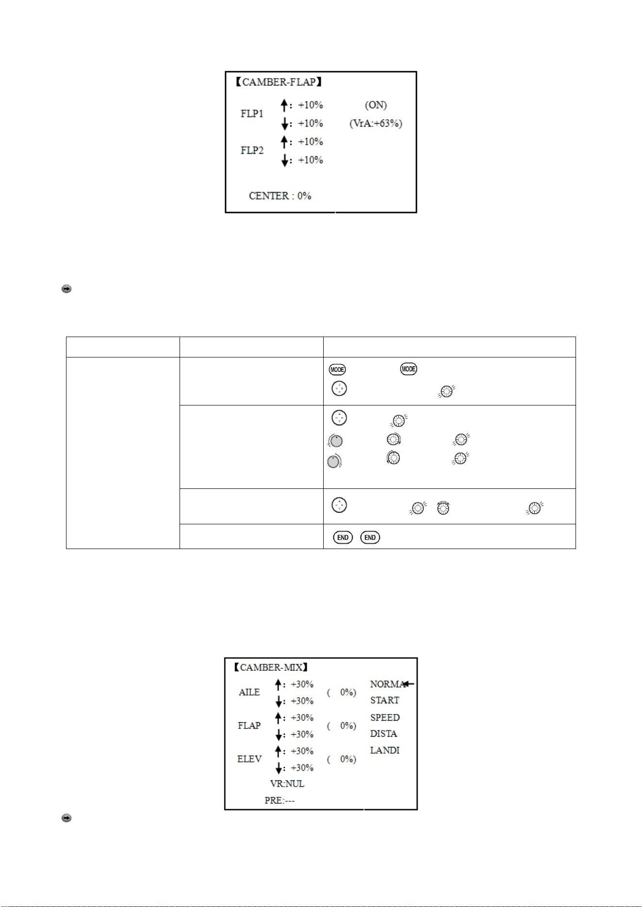
Radiolink Electronic Ltd
www.radiolink.com
59
ADJUSTABILITY
• Rate: -100% to +100%, with a default of +30%
• Center position (CENTER): The operation reference point of flap can be offset. -100% to +100%,
with a default of 0%.
Note: When changing the polarity of a rate, "change rate dir?" is displayed for a check. Please
set up after pressing DIAL for 1 second and canceling an alarm display.
Goals
Steps
Inputs
Ex: Set the maximum
travel of 35% of the
total flap travel.
Open the CAMBER FLAP
function.
to BASIC . again to ADVANCE
to CAMBER-FLP,
Adjust the up/down trim
amount separately.(Ex: adjust
to 35%)
to FLP 。
VR (A), to 35%,
VR (A), to 35%, 。
Repeat.
Or: adjust the center position
of flap servo
to CENTER , to desired point.
Close
4.3.7 Camber Mixing:
This function adjusts the mixing rate of camber operation which operates the wing camber (ailerons
and flaps) in the negative and positive directions. The aileron, flap, and elevator rates can also be
adjusted independently and attitude changes caused by camber operation can be corrected.
Also the operation reference point of camber control can be offset. (PRE)
Note:
Camber control is not assigned at initial.
ADJUSTABILITY:
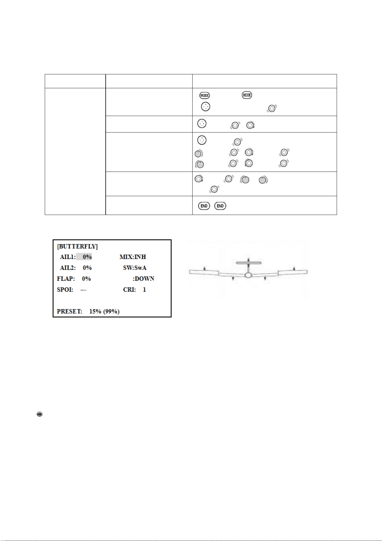
Radiolink Electronic Ltd
www.radiolink.com
60
• Rate: -100% to +100%, with a default of +30%
• Reference point (PRE): The operation reference point of camber control can be offset. -100% to
+100%, with a default of 0%.
Goals
Steps
Inputs
Ex: set the mixing
amount for aileron to
40%, camber control
to VR (E), reference
point to desired
point.
Open the CAMBER MIX
function.
to BASIC . again to ADVANCE
to CAMBER-MIX,
Choose desired slider.
to VR , to VrA
Adjust the mixing amount for
AILE. (Ex: adjust to 40%)
to FLP
to VrA , to 40%,
to VrA , to 40%,
Set the reference point.
to PRE , or VrA to desired
point for 1 sec.
Close
4.3.8 BUTTERFLY (crow) mixing
BUTTERFLY simultaneously moves the flaps, twin ailerons and elevator, and is usually used to make
steep descents or to limit increases in airspeed in dives. Separate two BUTTERFLY settings are
available. (CRI1/CRI2)
ADJUSTABILITY:
• Activation: Get proportional by moving the THROTTLE STICK.
• Switch: Mix SWITCH is selectable. A to H: SWITCH A to H. Also LOGIC SW (Lsw1 to 3) may be
assigned. NULL: always on.
• Inversely proportional to THROTTLE STICK: provides a proportional increase in amount of airbrake
action as THROTTLE STICK is lowered (when SWITCH A (assignable) is in down position). Includes
selectable stick position where airbrake begins. If you would like to have the airbrake be directly
proportional to throttle stick, you will need to reverse the THR-REV function.
Note:
this changes the throttle stick direction for all models.
INSTRUCTIONS:
• Elevator settings: (Adjustable in the B.FLY-ELE)
B.FLY-ELE works linking with BUTTERFLY function. Elevator rate is adjustable in a 3 point curve.
Point 1: PRESET point. (Fixed)
Point 2: MID point. Position and rate are adjustable.
Point 3: END point. Position and rate are adjustable.
• Delayed reaction: You can suppress sudden changes in your model's attitude when BUTTERFLY is
activated by setting the delay (DELAY) item, to slow down the elevator response, allowing the
flaps/ailerons/elevator to all reach their desired end point together. A setting of 100% slows the servo to
take approximately one second to travel the prescribed distance.
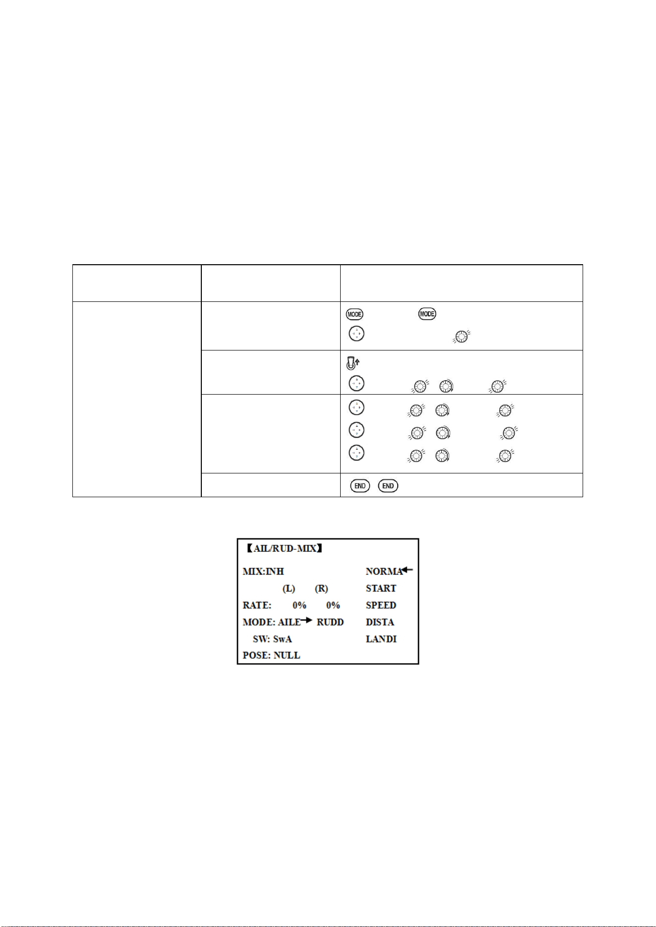
Radiolink Electronic Ltd
www.radiolink.com
61
• Channels controlled: Twin ailerons, flap and spoiler may be set independently in BUTTERFLY,
including set to 0 to have no effect.
• Twin aileron servos: If AIL-DIFF function is inhibited, then AIL1 and AIL2 settings will have no
effect. If AIL-DIFF is active, then CH1 and CH7 may be independently adjusted.
• Normally both ailerons are raised equally in BUTTERFLY, and the elevator motion is set to
maintain trim when the ailerons rise. Different amounts may be set for each aileron to correct for
torque reactions and other unique characteristics of the model.
Be sure you understand what dropping ailerons will do when in BUTTERFLY. Along with creating an
enormous amount of drag (desirable for spot landings), this also creates "wash-in", a higher angle
of attack where the ailerons are, and encourages tip stalling. If you are using this for aerobatic
performance and not "sudden stops", consider raising the ailerons and dropping the flaps in stead
as shown in the diagram above.
Goals
Steps
Inputs
Activate BUTTERFLY.
Adjust the aileron and
flap travel to 75%
Elevator setting is
adjustable in the
B.FLY-ELE.
MIX switch is selectable
Open the BUTTERFLY
function
to BASIC . again to ADVANCE
to BUTTERFLY,
Activate the function
SWA to UP position
to MIX , to OFF
Adjust the travels as
needed.
(Ex: Aileron each 75%, Flap
75%)
to AIL1 , to 75%,
to FLP , to75%,
to AIL2 , to 75%,
Close
4.3.9 AILE/ RUDD MIX
You can select a pre-programmed mix which is used to mix the rudders with aileron operation or the
ailerons with rudder operation.
Aileron-to-rudder mix (AILERUDD): automatically creates a "coordinated turn".
Rudder -to-aileron mix (RUDDAILE): used to counteract undesirable roll (roll coupling) that
happens with rudder input, especially in knife-edge.
ADJUSTABILITY:
• RATE range of -100 to +100. Negative setting would result in opposite rudder (aileron) action from
aileron (rudder).
• SWITCH A-H fully assignable. Also LOGIC SW (Lsw1 to 3) may be assigned.
• POSITION fully assignable, including NULL (mix always on) and Up&Cntr and Cntr&Dn to activate
the mix in 2 separate positions of the same SWITCH.
• Condition: The separate AILERUDD setting for each flight condition can be set.
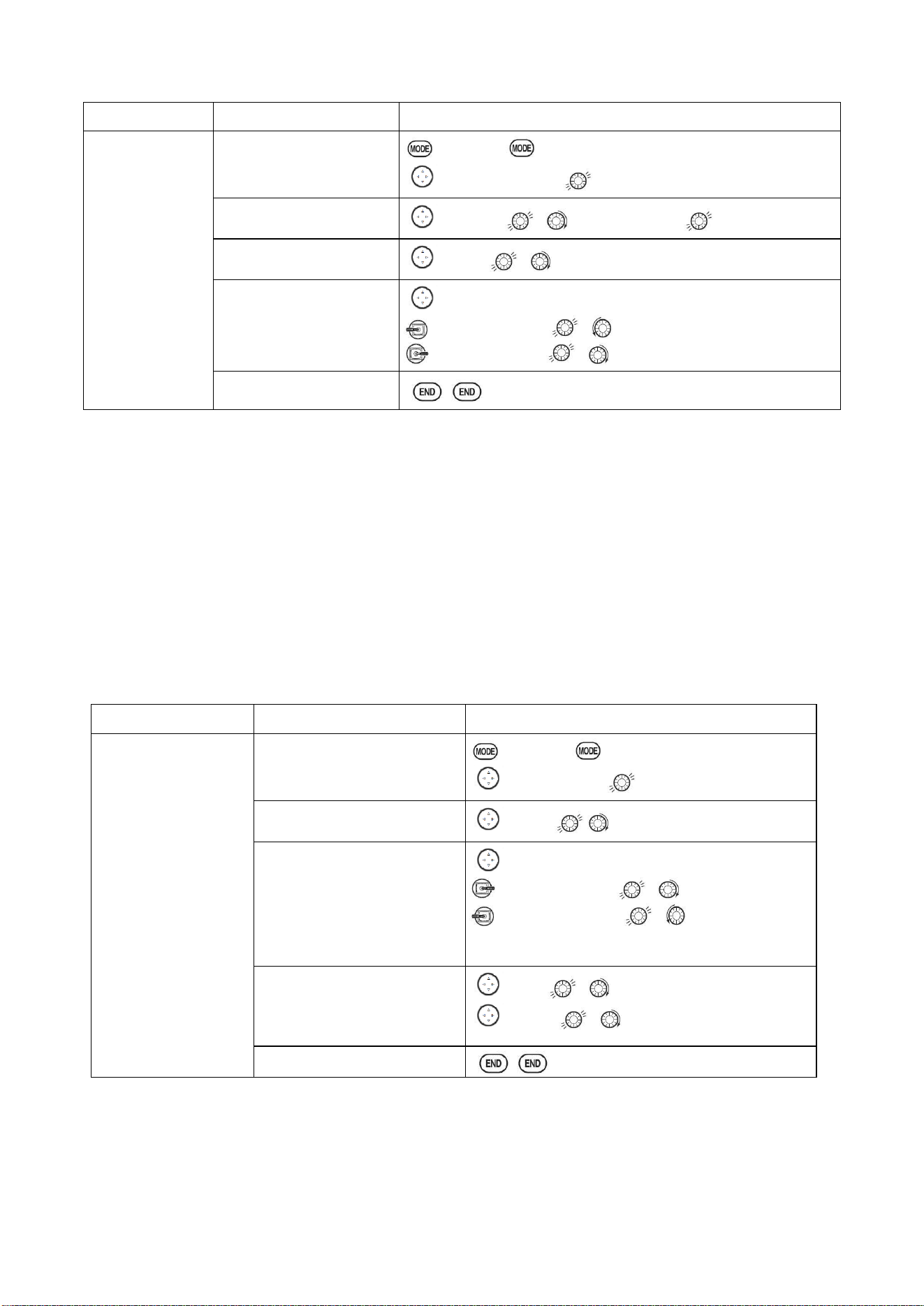
Radiolink Electronic Ltd
www.radiolink.com
62
Goals
Steps
Inputs
Ex:RUDD-AILE,
25%,no switch,
corrects roll
coupling.
Open AIL/RUD-MIX
submenu.
to BASIC . again to ADVANCE
to AIL/RUD-MIX,
Select the mixing mode.
to MODE , to RUDD-AILE
Activate the function
to MIX , to ON
Set the rate (Ex:100%
each way)
to RATE
RUDDER STICK , to +25%
RUDDER STICK , to +25%
Close
4.3.10
ELEV-FLAP mixing (see GLID menu 3.3.7)
4.3.11 AILE-FLAP(GLID 2A+2F only):
This pre-programmed mix is used to create full span aileron action on a glider
with 4wing servos. This increases the roll rate and decreases induced drag. For normal flying, a
value of about 50% is often used. For slope racing or F3B models in speed runs, you may wish to
use a larger value approaching 100%.
ADJUSTABILITY:
• RATE range of -100 to +100. Negative setting would result in opposite aileron action from flaps.
• SWITCH A-H fully assignable. Also LOGIC SW (Lsw1 to 3) may be assigned.
• POSITION fully assignable, including NULL (mix always on) and Up&Cntr and Cntr&Dn to activate
the mix in 2 separate positions of the same SWITCH.
• Condition: The separate AILE-FLAP settings for each flight condition can be set.
Goals
Steps
Inputs
Turn on AILE-FLAP
mixing. Set rate to
100% for maximum
possible flap travel
with ailerons .Assign
to SWITCH C center.
Open AILE-FLAP submenu.
to BASIC . again to ADVANCE
to AILE-FLAP,
Activate the function
to MIX , to ON
Set the rate (Ex:100% each
way)
to FLP1
AILERON STICK , to 100%
AILERON STICK , to 100%
Repeat above to set FLP2
Assign the SWITCH and
position.
to SW , to SwC
to POSI , to UP
Close
4.3.12 SPOILER MIX (GLID):
Moves the spoiler by flipping the assigned switch and is used to make steep decent. SPOILER MIX
works linking with BUTTERFLY MIX.
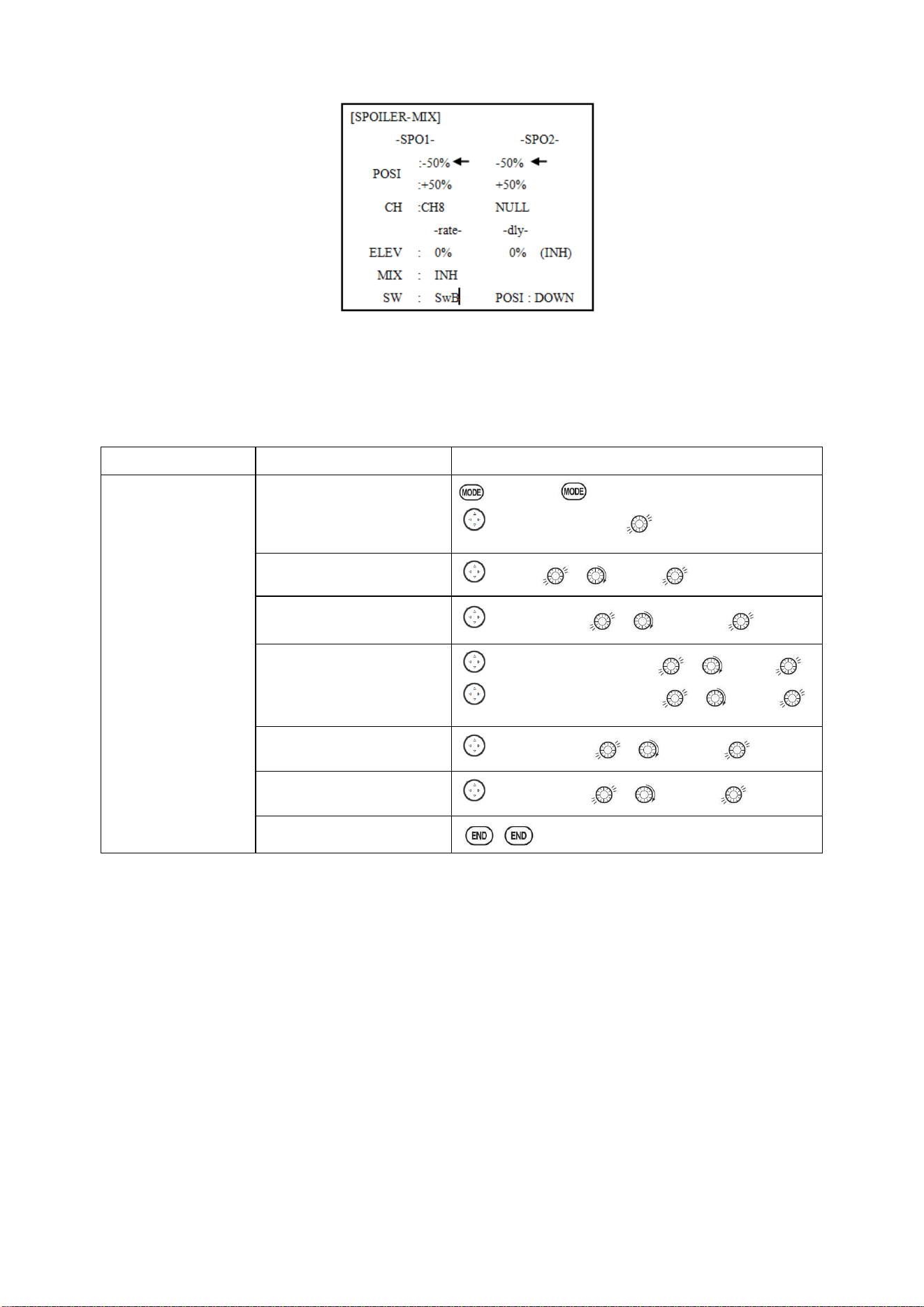
Radiolink Electronic Ltd
www.radiolink.com
63
ADJUSTABILITY:
• Position: -100% to +100%, with a default of -50% (off), +50% (on)
• Channel: Spoiler 1: ch8, or 3 (ch8 or 3*), Spoiler 2: NULL, or 3 (NULL or ch3*) *GLID (2A+2F)
mode.
• Elevator setting: Rate: -100% to +100%, Delay: 0% to 100%
• SWITCH A-H fully assignable. Also LOGIC SW (Lsw1 to 3) may be assigned.
Goals
Steps
Inputs
2-servo spoiler mode.
Adjust the spoiler
servo position to 60%
Open the SPOILER MIX
function and move to 2
nd
page.
to BASIC . again to ADVANCE
to SPOILER - MIX,
Activate the function.
to MIX , to ON.
Assign the SPO2-CH.(Ex:
CH3)
to –SPO2- CH , to CH3,
Adjust the spoiler servo
position. (Ex:
SPO1/SPO2=+55% to
+60%)
to –SPO1-POSI to -50%, , to 60%,
to –SPO2-POSI to +50%, , to 60%,
Optional: Set the elevator
rate.(Ex:10%)
to –rate- ELEV , to 10%,
Optional: set the delay.
(Ex:25%)
to –dly- ELEV , to 25%,
Close
4.3.13
FLAP-TRIM (see GLID 3.3.4)
4.3.14 CONDITION
Channel 3's function is selectable in the ARBK-FUNC item. (Throttle stick, switches, or knobs) By
choosing except STK, channel 3's function may be separated from Butterfly’s function, so channel 3
can be used for other functions.
ADJUSTABILITY:
• Channel 3's function:
STK: THROTTLE STICK
Sw-A to H: SWITCH A to H
Vr-A to Vr-E: KNOB A to E
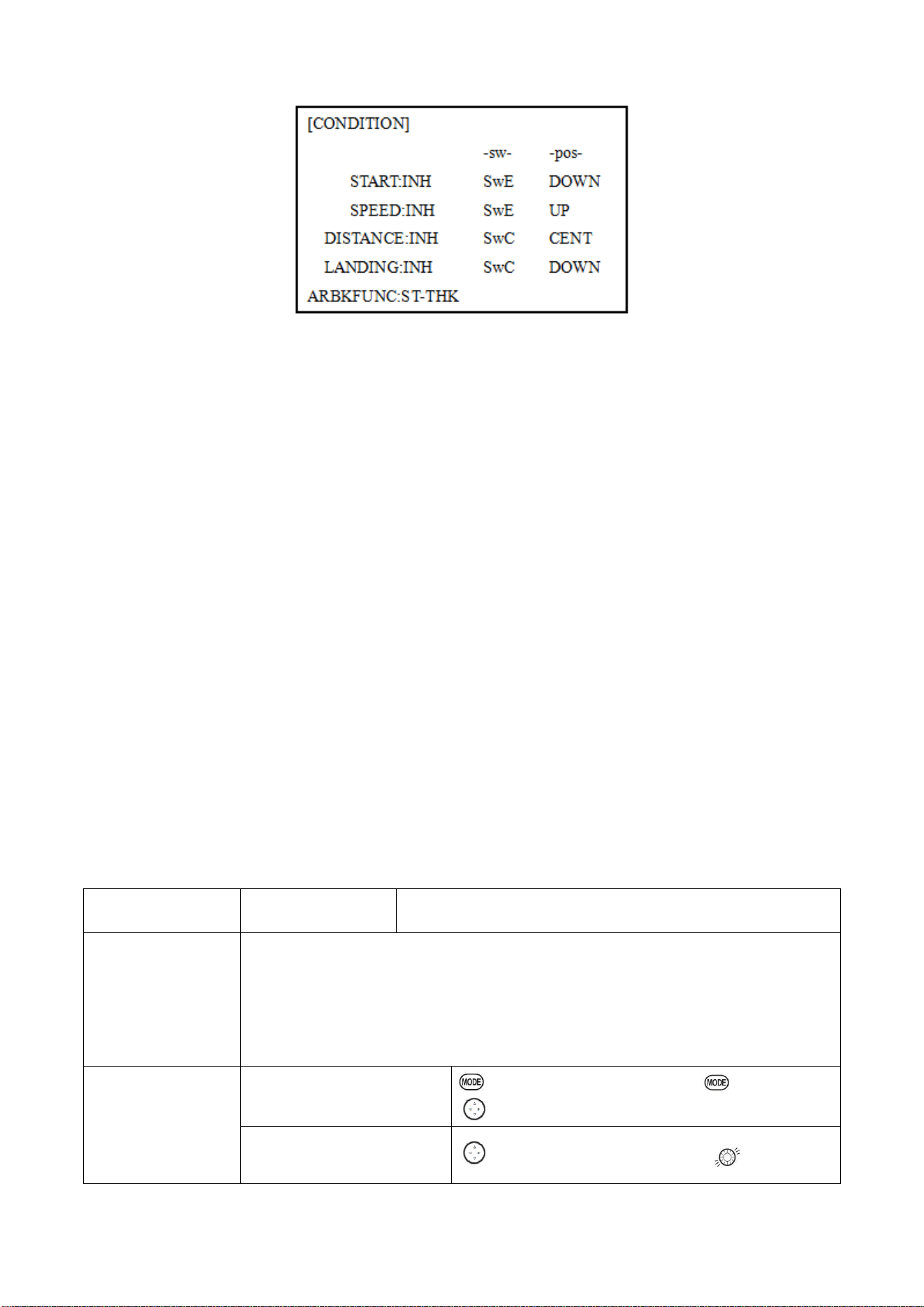
Radiolink Electronic Ltd
www.radiolink.com
64
Part. 5 HELICOPTER MODEL FUNCTIONS
Please note that nearly all of the BASIC menu functions are the same for airplane (ACRO setup),
sailplane (GLID setups), and helicopter (HELI) setups. The features that are identical refer back to
the ACRO chapter.
5.1 BASIC SETTING WITH HELICOPTER
This guideline is intended to help you set up a basic (H-1) helicopter, to get acquainted with the
radio, to give you a jump start on using your new radio, and to give you some ideas and direction on
how to do even more with this powerful system than you may have already considered.
Briefly, the typical helicopter's controls are as follows:
• Aileron: Changes cyclic lateral (roll). Roll the helicopter. Tilt the swash plate to the left or right CH1.
• Elevator: Changes cyclic pitch. Change the helicopter’s angle of attack (nose up or nose down).
Tilt the entire Swash plate fore and aft. CH2.
• Rudder: Change the angle of the tail rotor and yaw the helicopter left or right. CH4.
• Collective Pitch: Adjusts main rotor collective [angle of the paddles], changing the main blades’
pitch. Increased collective pitch (with throttle) causes the helicopter to rise. Moves in conjunction
with throttle on the THROTTLE STICK. CH6.
• Throttle: Open/close carburetor. Move in conjunction with collective pitch on the THROTTLE
STICK. CH3.
• REVO: mix that adds rudder in conjunction with pitch. This helps compensate for rotation of the
helicopter caused by the increased engine torque. (Never use REVO. mixing with a
heading0hold/AVCS gyro; the gyro already does this.)
Goals
Steps
Inputs
Prepare your
helicopter.
Install all servos, switches, receiver per your model's instructions. Set all trims, dials and
sliders to neutral.
Confirm all control linkages are 90 degrees (or per instructions ) from the servo
horn to the ball link for proper geometry and that no slop is present.
Mechanically adjust all linkages to get as close as possible to proper control throws
and minimize binding prior to radio set up.
Select proper mode
type for your model.
Ex: HELI H-1
In the BASIC menu, find
PARAMETER.
for 1s to BASIC.(If ADVANCE again) .
to PARAMETER , PUSH
Go to MODEL TYPE.
to MODEL TYPE, then to TYPE.
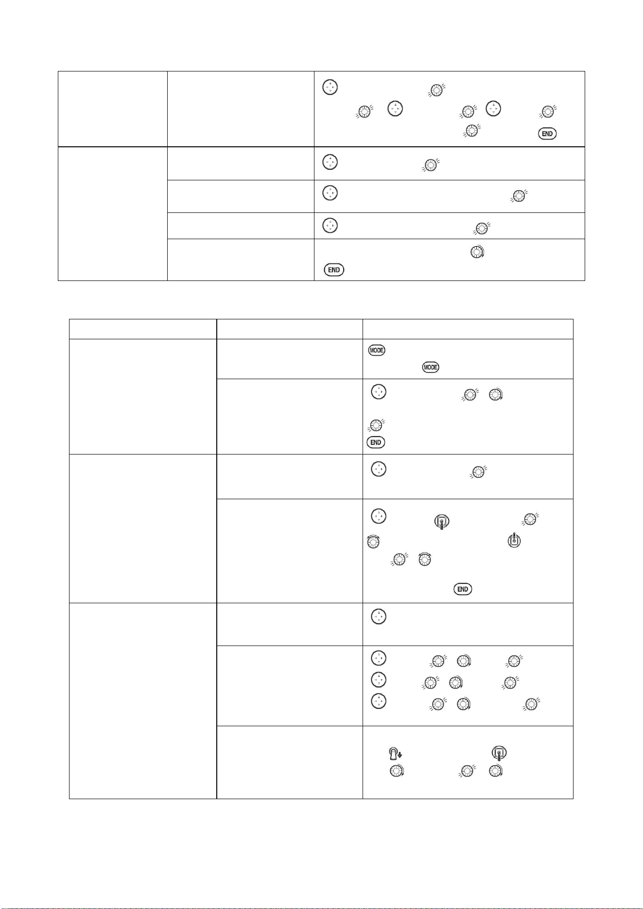
Radiolink Electronic Ltd
www.radiolink.com
65
Select proper mode type. Ex:
HELI H-1. Confirm the
change.
Close.
to HELICOPTER. for 1 sec. ‘Are you sure?’
displays , to SWASH ,
to H-1
for
1sec,’Are you sure ?’ displays. to confirm.
Then , NAME the
model.
In the BASIC menu, find
PARAMETER.
to MODEL SEL.
Go to MODEL SEL.-NAME
to Name(1
st
character is highlighted)
Input name.
to change the first character.
Close the submenu when
done.
When proper character is display. to next. Repeat.
Goals
Steps
Inputs
Reverse servos as needed for
proper control operation. Ex:
Left Rudder Stick results in
leading edges of tail rotor
blades moving left. Reverse to
operate properly.
In BASIC menu, open
Reverse.
for 1s to BASIC.(If
ADVANCE again) .
to REVERSE ,
Choose desired servo and
reverse its direction of travel.
Ex: reverse rudder servo.
to CH4:RUDD , to REV is
highlighted. ‘Are you sure ?’ displays
for 1 sec.
Adjust travels as needed to
match model’s recommended
throws.(usually listed as high
rates.
In BASIC menu, choose END
POINT.
to END POINT to choose end
point.
Adjust the servo’s end points.
(Ex: elevator servo).
Return to BASIC menu.
to ELEV. Elevator Stick ,
until up travel is as desired. Elevator
Stick , until down travel is as
desired.
Repeat as needed.
Activate THR-CUT.
Open THROTTLE-CUT
function.
to THR CUT
Activate the function. Choose
desired switch and position to
activate.
to MIX, , to OFF
to SW , to SwC,
to POSI , to DOWN,
With THROTTLE STICK at
idle, adjust the rate until the
engine consistently shuts off,
but throttle linkage is not
binding.Close
SwC to down position, Throttle
Stick ,to RATE , until shuts off.
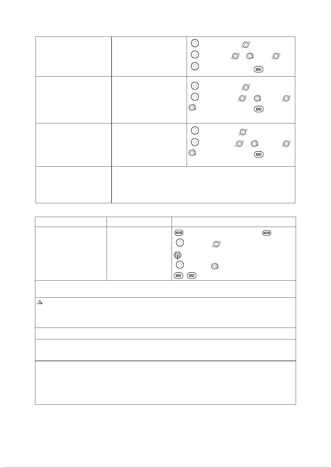
Radiolink Electronic Ltd
www.radiolink.com
66
Set up throttle curve for
normal. (Usually changes will
not need to be made prior to
first flight.)
Open the THR-CURV/NOR
function. Adjust if needed.
Close the function.
to THR-CURVE ,COND:NORM,
to point 1> , to 5%, .
Move to next. Repeat.
Set up collective pitch curve
for normal as base of -4,
center of +5,end of +8 to +10
degrees of blade pitch for
aerobatics.2 (If just learning to
fly, ask your instructor.)
Open the PIT-CURV/NOR
function.
Adjust each point to desired
Curve.(Ex: first Point:8%)
Close the function.
to PIT-CURVE , COND:NORM,
to point 1> , to 8%, ,
to next point. Repeat.
Set up REVO. Mixing for
normal. (For heading-hold
gyros, inhibit REVO.)
Open the REVO./NOR
function.
Adjust to your desired starting
point.
(Ex: 10%.)
Close the function.
to REVO.MIX , COND:NORM,
to point 1> , to 10%, ,
to next point. Repeat.
Confirm gyro direction.
With radio on, move helicopter’s tail to the right by hand.
The gyro should give right rudder input (leading edge of the tail rotor
blades move left).
If the gyro gives the opposite input, reverse direction on the gyro unit itself.
Goals
Steps
Inputs
Learn how to operate
HOVERING PITCH
and
HOVERING THROTTLE
Notice at half throttle,
the VR(B) dial adjusts
the throttle separately
from the pitch. VR(A)
adjusts the pitch
separately from the
throttle.
for 1s to BASIC.(If ADVANCE again) .
to SERVO .
Throttle stick to center
VR (B), VR (A).
Be sure to follow your model’s instructions for preflight checks, blade tracking, ect. Never assume a set of
blades are properly balanced and will track without checking.
Check receiver battery voltage! Always check voltage with a voltmeter prior to each and every engine
start.(Never assume being plugged in all night means your radio gear is ready to fly).Insufficient charge,
binding servo linkages ,and other problems can result in a dangerous crash with the possibility of injury to
yourself, others and property.
Confirm the swashplate is level at 0 travel. Adjust arms if needed.
Apply full collective and check that the swashplate remained level and there is no binding. Repeat for full
cyclic pitch and
roll. If not, adjust as needed to correct in
END POINT
:
Important note: prior to setting up throttle hold, idle-ups, offsets, etc, be sure to get your normal condition
operating properly.
Checking setup prior to going airborne: Check voltage! Then, with the assistance of an instructor, and having
completed all range checks, etc, gradually apply throttle until the helicopter becomes “light on the skids.”
Adjust trims as needed to correct for any roll, pitch, or yaw tendencies. If the tail “wags,” the gyro gain is too
high. Decrease gyro gain.
1. Periodically move the throttle stick to full and back down to ensure proper servo settings.
2. It is critical that dials A and C be centered when the pitch and throttle curves are setup.
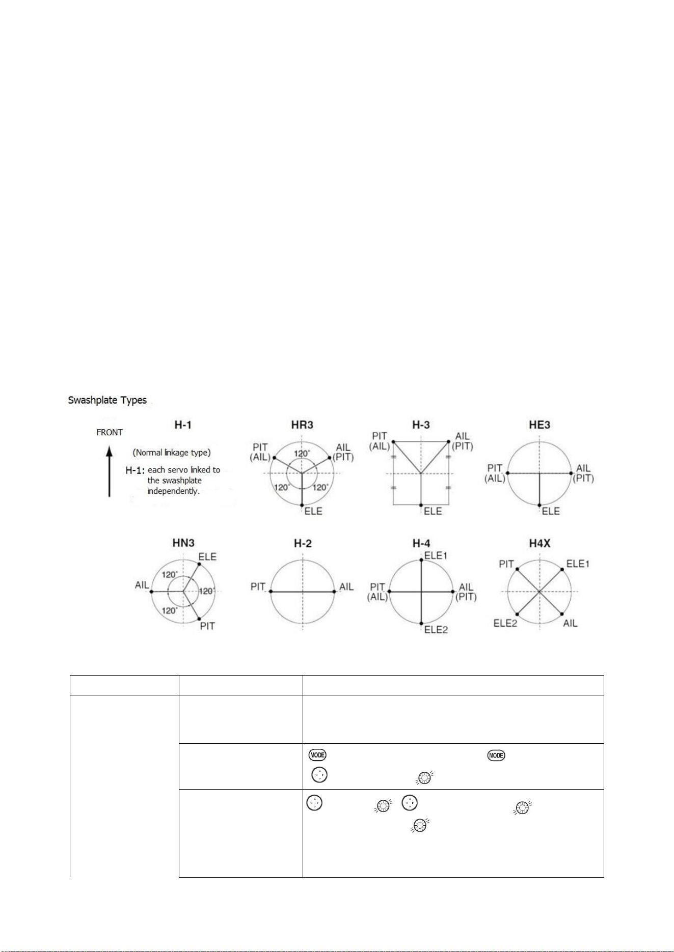
Radiolink Electronic Ltd
www.radiolink.com
67
5.2 HELI-SPECIFIC BASIC MENU FUNCTIONS
MODEL TYPE: This function of the PARAMETER submenu is used to select the type of model
programming to be used. Before doing anything else to set up your model, first you must decide
which MODEL TYPE best fits your MULTIROTOR.
HELICOPTER SWASHPLATE TYPES:
The AT10II radios support 8 basic swash plate setups, including "single servo" (H-1-most
helicopters use this type) and 7 types of CCPM (cyclic and collective pitch mixing). A "single servo"
swash plate uses one servo for each axis: aileron, elevator (cyclic pitch), and collective pitch.
CCPM helicopters utilize a combination of servos working together to achieve the 3 axes of motion.
There are 7 basic CCPM types, displayed below. CCPM has several advantages, the most obvious
of which is far less mechanical complexity to properly move the swash plate of the helicopter.
Additionally, several servos working in unison (ex: HR3, all 3 servos together create elevator
movement) dramatically increases the torque available as well as the precision and centering.
Please note that some helicopters are type HR3 or HN3, except off by 180 degrees. If your model 's
swash plate is off by 180 you will still use that swash plate type, but also use SWASH AFR to adjust
the functions as needed until it operates properly. Additionally, different angles of CCPM may also
be created utilizing the fully assignable programmable mixes.
5.2.1 Swash Plate Types
Goals
Steps
Inputs
Change the model
type and swashplate
of model#3 from
MULTIROTOR to
120 degree CCPM
with 2 servos
working in unison
for collective pitch
and aileron (Ex:
HELI HR3)
Confirm you are using
the proper model
memory(Ex:3)
On home screen, check model name and # on top left. If it is
not the correct model (Ex:3) see MODEL SEL.
Open PARAMETER, go
to MODEL SEL.
for 1s to BASIC.(If ADVANCE again) .
to MODEL SEL.
Select proper MODEL
TYPE (HELICOPTER)
Confirm
to TYPE. , to HELICOPTER. for 1sec. ‘Are
you sure?’ Displays.
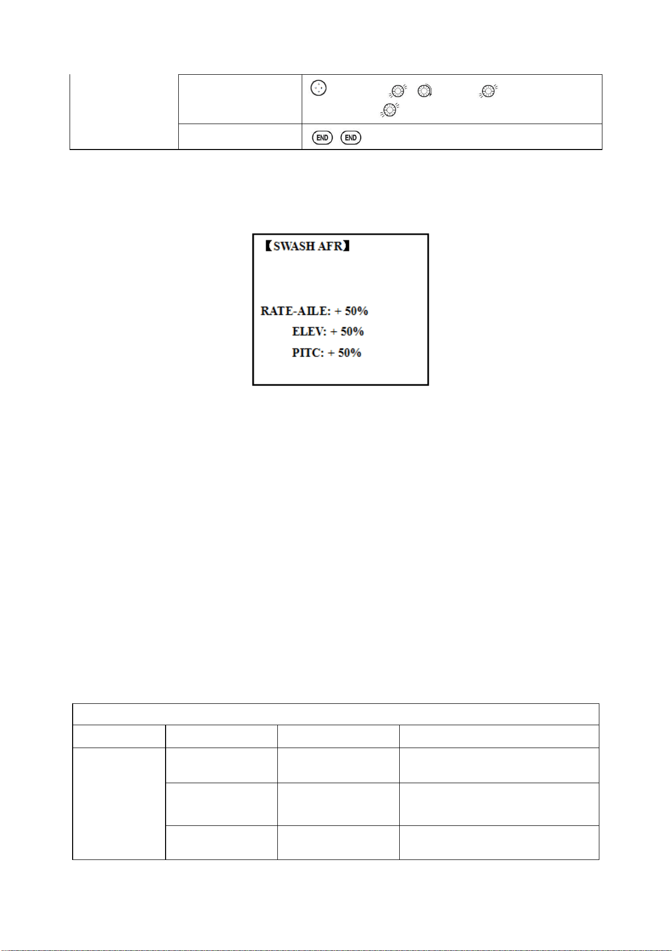
Radiolink Electronic Ltd
www.radiolink.com
68
Change to desired
SWASH TYPE (Ex:
HR3) Confirm.
to SWASH. , to HR3,
for 1 sec. ‘Are you
sure?’ displays.
Close
Radio emits a repeating “beep” and shows progress on screen as the model type is being changed.
Note that if the power switch is turned off prior to completion, the model type will not be changed.
5.2.2 SWASH AFR (not in SWH1)
Except SWASH PLATE, function menu of helicopter is same as GLID/ ACRO. Please find the
former instructions.
Swash plate function rate settings (SWASH AFR) reduce/increase/reverse the rate (travel) of the
aileron, elevator (except H-2) and collective pitch functions, adjusting or reversing the motion of all
servos involved in that function, only when using that function. Since these types utilize multiple
servos together to create the controls, simply adjusting a servo's REVERSE or END POINT would
not properly correct the travel of any one control. Since H-1 uses one servo for each function, there
is no need for AFR in H-1.
Since aileron always uses no more than 2 servos, check it first. Either both operate properly (no
change needed), both operate backwards (reverse the whole function), or one servo operates
backwards (reverse that servo alone). Next check elevator. Remember, the aileron servo(s) operate
correctly, so if elevator does not, we should only have 2 choices left—the whole function needs to
be reversed, or the servo(s) not shared with aileron need to be reversed. If aileron and elevator are
not working properly, the only thing that could be wrong is the whole direction collective operates
(reverse the whole function). In our example, HR3 is 180 degrees off from the swash plate of the
Caliber. Therefore, it is very likely that several functions will not operate properly. The collective
pitch operation is backwards; but reversing all three servos would also reverse the aileron and
elevator operations. Changing the collective pitch rate, however, from +50% to -50%, will reverse
the collective pitch without affecting the aileron action.
Checking For Proper Motion On An HR3 Swashplate
HR3 Swash Typ
Proper Motion
Wrong Motion
How to Fix
AILERON
STICK.
Swashplate tilts left.
Reverse
AIL
setting in
SWASH
to
-50%
.
Swashplate tilts right.
Back of Swashplate
moves up.
Ch6 servo moves incorrectly;
REVERSE.
Back of Swashplate
moves down.
Ch1 servo moves incorrectly;
REVERSE.
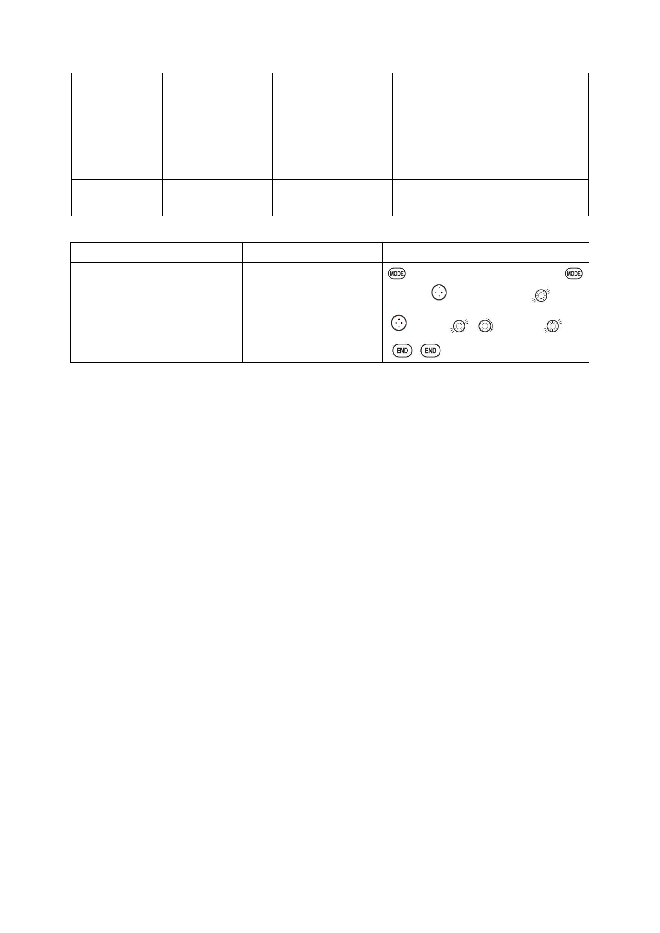
Radiolink Electronic Ltd
www.radiolink.com
69
ELEVATOR
STICK.
Front of swash plate
moves
down;
Swashplate moves
the opposite.
Reverse ELE setting in SWASH. (ex:
+50 to -50)
back of swashplate
moves up.
Entire swashplate
moves up.
Ch2 servo moves incorrectly;
REVERSE.
RUDDER
STICK.
The leading edges of
tail blades rotate left.
Blades rotated right.
REVERSE the rudder servo.
THROTTLE
STICK.
Entire Swashplate
lifts.
Swashplate lowers.
Reverse PIT setting in SWASH.
Goals
Steps
Inputs
Adjust the travel of the collective
pitch from +50% to -23%,
reversing the travel of all 3 servos
and decreasing their travel in
collective pitch only, on an HR3
SWASH TYPE.
Open SWASH AFR
function.
for 1s to BASIC.(If ADVANCE
again) . to SWASH
AFR
Adjust PITC travel to -23%
to PITC , to -23%,
Close
5.3 HELI-SPECIFIC ADVANCE MENU FUNCTIONS
5.3.1 THR-CURVE and PIT-CURVE:
These 7-point curves are utilized to best match the blade collective pitch to the engine RPM for
consistent load on the engine. Curves are separately adjustable for normal, idle-up 1, idle-up 2, and
idle-up 3. In addition, a separate collective pitch curve is available for throttle hold. Sample curves
are displayed in the appropriate setup types (ex: normal flight condition) for clarity.
Suggested defaults:
• Normal: Collective pitch curve that results in points 1, 4 and 7 providing .4, +5, (+8 to +10)*
degrees pitch. A throttle curve setting of 0, 25, 36, 50, 62.5, 75, 100%.
• Idle-ups 1 & 2: Idle-ups 1 and 2 are typically the same except for the gyro settings, with one being
heading-hold/AVCS and the other being normal mode. The pitch curve will likely be similar to the
normal curve above.
• Idle-up 3: Collective pitch curves that result in points 1, 4 and 7 providing (.8 to .10), 0, (+8 to +10)
degrees. A throttle curve of 100, 75, 62.5, 50, 62.5, 75, 100 provide full throttle for inverted
maneuvers.
• Throttle Hold pitch curve: Start with the normal pitch curve (for inverted autos, start from the
idle-up 3 pitch curve), but increase the last point approximately 1-2°, if available, to ensure sufficient
pitch at landing.
This default recommendation assumes you are doing forward flight. If you are just learning, please
follow your instructor's guidance. Some instructors like a +1 base point for training so that the
helicopter comes down very slowly, even if your instincts pull the throttle/collective stick to the
bottom in a hurry.
ADJUSTABILITY:
• Normal condition curves are editable in the BASIC menu for convenience.
• All curves may be adjusted in the ADVANCE menu.
• Automatically selected with the proper condition.
• The idle-up curves are programmed to maintain constant RPM even when the collective pitch is
reduced during flight (including inverted).
• To change which condition’s curve is being edited, cursor up to <COND> and change the curve
named.
• For clarity, the name of the condition currently active (switched on in the radio) is shown in
parentheses behind name of condition whose curve is being edited. (Example: see curve displays
below. Note that the normal condition is active but the idle-up 1 condition’s curves are currently
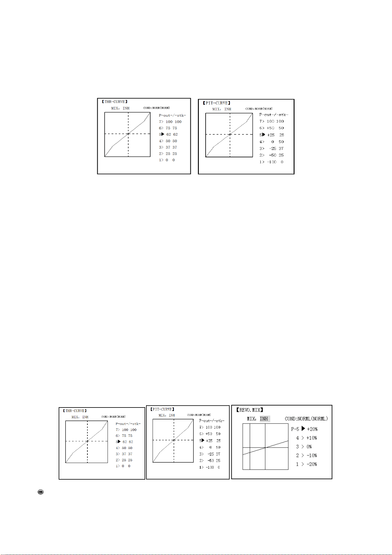
Radiolink Electronic Ltd
www.radiolink.com
70
being edited.
• Moving and deleting the curve point: The curve point (-stk-) can be moved to the left or right by
turning the DIAL (up to 2% in front of the adjoining point) and deleted/returned by pressing the DIAL
for one second alternately.
• Idle-ups and throttle hold pitch curves may be edited even before the conditions have been made
active. Activating their throttle curves activates these conditions.
5.3.2 REVO MIX:
This 5-point curve mix adds opposite rudder input to counteract the changes in torque when the
speed and collective pitch of the blades is changed.
ADJUSTABILITY:
• Three separate curves available: normal for hovering; idle-ups 1 and 2 combined; and idle-3.
• Normal condition curves are editable in the BASIC menu for convenience.
• All curves may be adjusted in the ADVANCE menu.
• Correct mix is automatically selected in-flight with each condition and automatically activated
when the throttle setup for that condition is activated in the programming (i.e. THROTTLE HOLD or
THR-CURVE.)
• To change which condition’s curve is being edited, cursor up above POINT5 and select. For clarity,
the name of the condition currently active (switched on at the radio) is shown in parentheses behind
the name of the condition whose curve is being edited.
Revo. Mixing rates are 5-point curves. For a clockwise-turning rotor, the rudder is mixed in the
clockwise direction when collective pitch is increased; for counterclockwise-turning, the opposite.
Change the operating direction setting by changing the signs of the numbers in the curve from plus
(+) to minus (-) and vice versa.
Suggested defaults:
Clockwise rotation: -20, -10, 0, +10, +20% from low throttle to high.
Counterclockwise rotation: +20, +10, 0, -10, -20% from low throttle to high.
Adjust to the actual values that work best for your model.
Revo. Curves for idle-ups are often v-shaped to provide proper rudder input with negative pitch and
increased throttle during inverted flight.(Rudder is needed to counter the reaction whenever there is
increased torque. In inverted flight, throttle stick below half has increased throttle and negative pitch,
therefore increasing torque and rotating the helicopter unless the revo. Mix is also increasing
appropriately.)
Note: The throttle and pitch curves for the normal condition is always on. They cannot be
inhibited. The other four conditions are activated with their throttle curves or throttle hold.
• THR-CURV/NOR: Inputs the normal (NORM) throttle curve, which is usually not a linear response
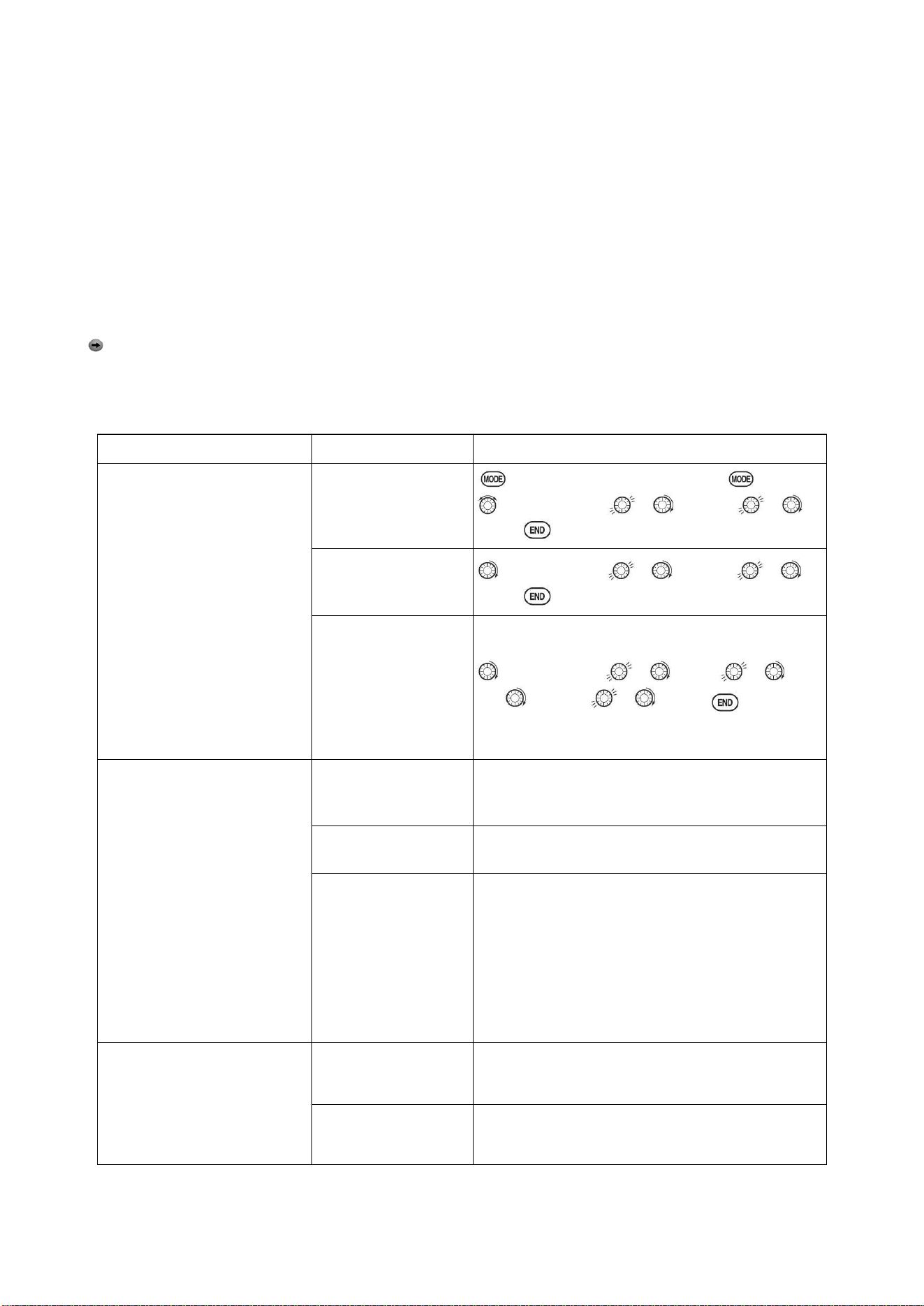
Radiolink Electronic Ltd
www.radiolink.com
71
to THROTTLE STICK motion. Adjusting point 4 of the curve adjusts the engine's RPM at the
THROTTLE STICK midpoint, the desired position for hovering. The other 6 points are then adjusted
to create the desired idle and maximum engine speed, and a smooth transition in-between.
• PIT-CURV/NOR: inputs the normal (NORM) collective pitch curve, the collective pitch curve for
flight near hover. The normal collective pitch curve is adjusted to match the throttle curve, providing
the best vertical performance at a constant engine speed, with a starting curve of 4 base, +5 neutral,
and +8 to +10 degrees of blade pitch maximum. You can program the response over a 7-point
curve for the best collective pitch angle relative to THROTTLE STICK movement.
• REVO./NORM: mixes collective pitch commands to the rudder (a PITCH-RUDDER mix) to
suppress the torque generated by changes in the main rotor's collective pitch angle, keeping the
model from yawing when throttle is applied.
Note: There are three revo, mixes available: normal (NORM), idle-up 1/2 (IDL1/2), and idle-up 3
(IDL3). All 3 are adjustable in the ADVANCE menu. Never use revo mixing in conjunction with
heading-hold/AVCS gyros. For details on revo, including default points for clockwise and
counterclockwise rotating rotors.
Goals
Steps
Inputs
Set up Normal Flight
Condition
Throttle/Collective Pitch
Curves and Revo.
Base point: Adjust base point
of throttle curve until engine
idles reliably on ground.
Adjust base point of collective
pitch curve to achieve -4
degrees of blade pitch.
Apply throttle until the
model sits ‘light’ on its
skids. Adjust
base point of
REVO
. until model does not
rotate its nose at all.
Open the
THR-CURVE, Adjust
the first point.(5%)
for 1s to BASIC.(If ADVANCE again) .
to THR-CURVE , to point 1 , to
5%,
。
Open the PIT-CURVE,
Adjust the first
point.(8%)
to PIT-CURVE , to point 1 , to
8%,
Open the REVO.MIX
Adjust the first
point.(4%)
to REVO.MIX , to MIX , to
ON. to point 1 , to 4%,
。
Hover point: Adjust
collective pitch curve to +5
degrees. Ease heli into a
hover. Land/shut engine
off. Adjust throttle curves
and rudder trim. Repeat until
model hovers smoothly at
half throttle. Rapidly apply
throttle from 1/4 to 1/2
stick. Adjust
REVO
.
points 2 and 3
until the model does not rotate
its nose up on throttle
application.
Adjust
THR-CURV/NOR
Repeat above as needed
Adjust
PIT-CURV/NOR
Repeat above as needed
Adjust
REVO.MIX
Repeat above as needed
High point: Adjust
collective pitch curve to +8
to +10 degrees. From hover,
throttle up rapidly. If
engine bogs, increase the
throttle curve. If engine
Adjust
THR-CURV/NOR
Repeat above as needed
Adjust
PIT-CURV/NOR
Repeat above as needed
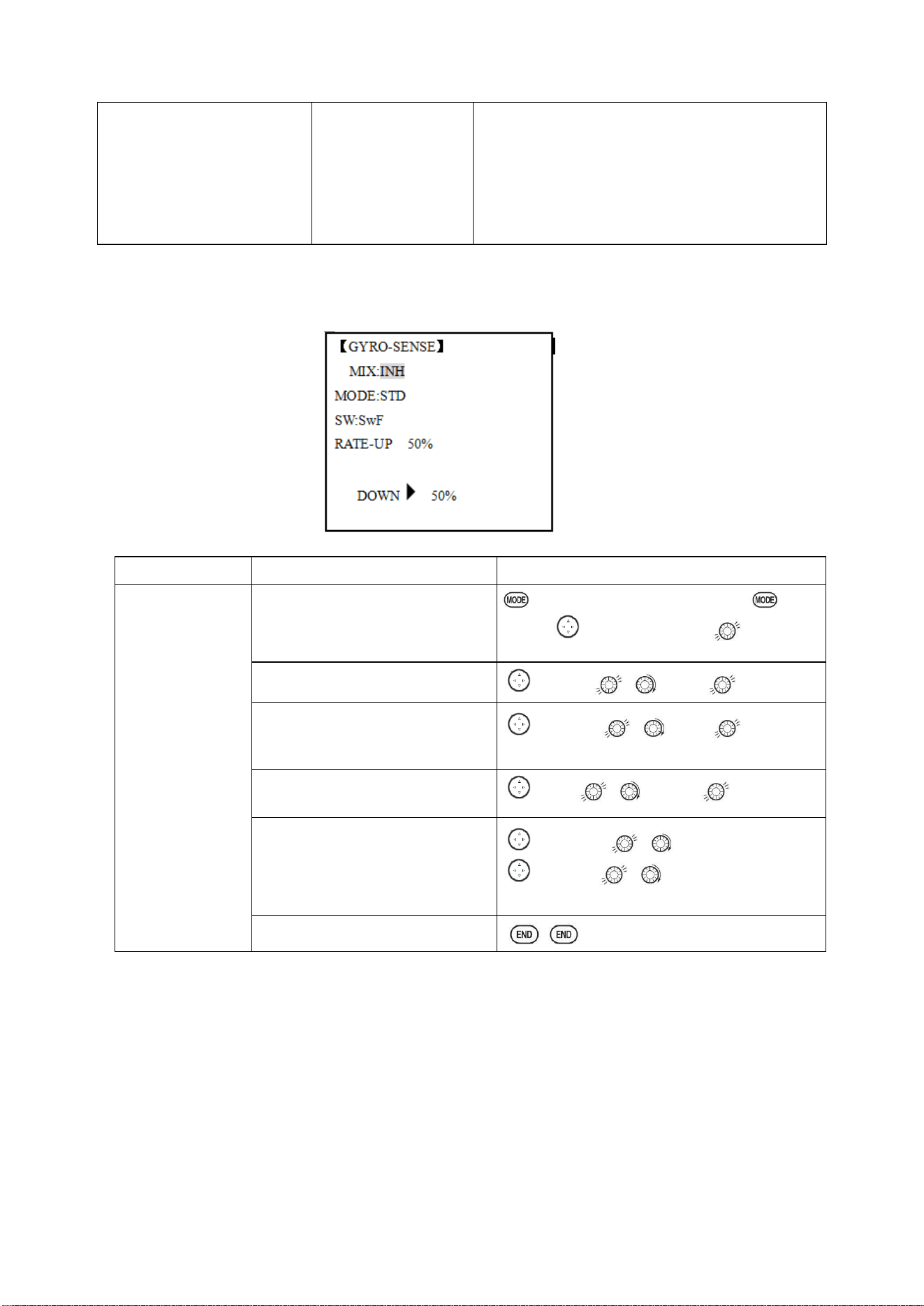
Radiolink Electronic Ltd
www.radiolink.com
72
over-revs, increase the
collective pitch curve at points
6 or 7. Apply full throttle
while hovering, then descend
back to
hover. Adjust
REVO
.
until the nose does
not change
heading.
Adjust
REVO.MIX
Repeat above as needed
5.3.3 GYRO SENSE
About GYRO SENSE, please refer to 3.3.12, by following steps:
5.3.4 THROTTLE HOLD
This function holds the engine in the idling position and disengages it from the THROTTLE STICK
when SWITCH AT10II is moved. It is commonly used to practice auto-rotation. Prior to setting up
THR-HOLD, hook up the throttle linkage so that the carburetor is opened fully at high throttle, then
use the digital trim to adjust the engine idle position. To have THR- HOLD maintain idle, move the
THROTTLE STICK to the idle position, then move the hold SWITCH on and off and keep changing
the offset value until the servo does not move. To lower the engine idle speed, or if you want to shut
off, input a more negative number.
ADJUSTABILITY:
• Idling position: Range of -50% to +50% centered about the throttle idle position to get the desired
engine RPM.
Goals
Steps
Inputs
Set up heading-
hold /AVCS gyro
with
heading-hold/AVC
S setting in
idle-ups 1 and 2
and normal mode
setting in idle- up3
and normal.
Open and activate the GYRO
SENSE function.
for 1s to BASIC.(If ADVANCE
again) .
to GYRO-SENSE
Activate the function.
to MIX , to ACT.
Optional: Change gyro types to
Heading- hold
(
GY
).
to MODE , to GY
Optional: Changes switch
assignment.
Ex: select
Cond
.
to SW , to Cond
Adjust gyro rates as needed.
(Ex:
NORM
,
IDL3
to
NOR 50%
.
IDL1
and
2
to
AVC 50%
as starting
points.)
to NORM, , to NOR 50%
to IDL1 , to AVC 50%
Repeat.
Close
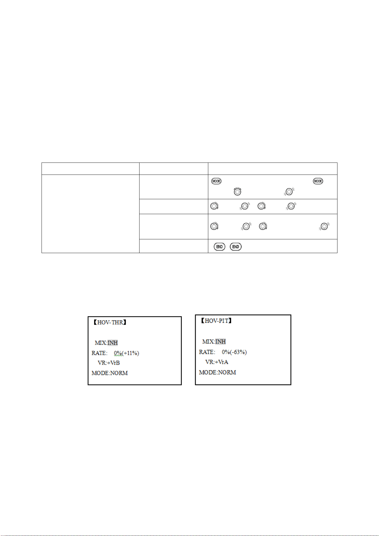
Radiolink Electronic Ltd
www.radiolink.com
73
• Switch assignment: Assigned to SWITCH E(AT10) or G (AT10) down. Adjustable in the
CONDITION (THR-HOLD item), (2-position type switch only)
• Throttle curve: Since the throttle is moved to a single preset position, no curve is available for
THR-HOLD.
• Collective pitch curve: Independent curve, typically adjusted to create a blade pitch range of -4%
to +10% to +12%, is automatically activated with THRHOLD.
• Revo. mix: Since revo. mix adjusts for torque from the engine, no revo. mix is available for
THR-HOLD.
• Priority: The throttle hold function has priority over idle-up. Be sure that the throttle hold and
idle-up SWITCHES are in the desired positions before trying to start the engine. (We recommend
starting your engine in throttle hold for safety reasons.)
• Gyro: Gyro programming includes an option to have a separate gyro setting for each condition,
including THR-HOLD. This avoids the potential problem of the user being in the wrong gyro setting
when going to THR-HOLD, resulting in an improper rudder offset and the model pirouetting.
Goals
Steps
Inputs
Set up throttle hold.
Determine desired throttle
position by
idling engine, turn
on
THR-HOLD
, and
adjust
percentage as required to reach
the desired running point.
Open
THR-HOLD
function.
for 1s to BASIC.(If ADVANCE
again)
to THR-HOLD
Activate the function.
to MIX , to OFF
Set desired engine
position.
to POSI , to desired percent
Close
5.3.5 HOVERING ADJUSTMENTS (HOV-THR and HOV-PIT):
Hovering throttle and hovering pitch are fine-turning adjustments for the throttle and collective pitch
curves individually, affecting performance only around the center point and only in the normal
condition. They allow in-flight tweaking of the curves for ideal setup.
ADJUSTABILITY:
• Rotor speed changes caused by temp., humidity, altitude or other changes in flying conditions are
easily accommodated.
• Both adjustments may be inhibited if not desired.
• Both adjustments may also be set to NULL, temporarily turning off the knob but maintaining the
last memorized setting.
• Adjustments may be memorized and then the knobs returned to center point to use that amount of
adjustment, allows easy use of the trimming knobs for multiple models. (Note that when
memorization is repeated with the knob offset from center, the trim value accumulates.)
• Adjustments are quickly reset to the initial value by turning the dial until the trim reads 0%,
memorizing, then returning the knob to its center position.
• Note that all functions, including these, assume the model hovers at half stick.
•Available in normal (NORM) or normal/ idle-up1 (NORM/IDL1) condition only.
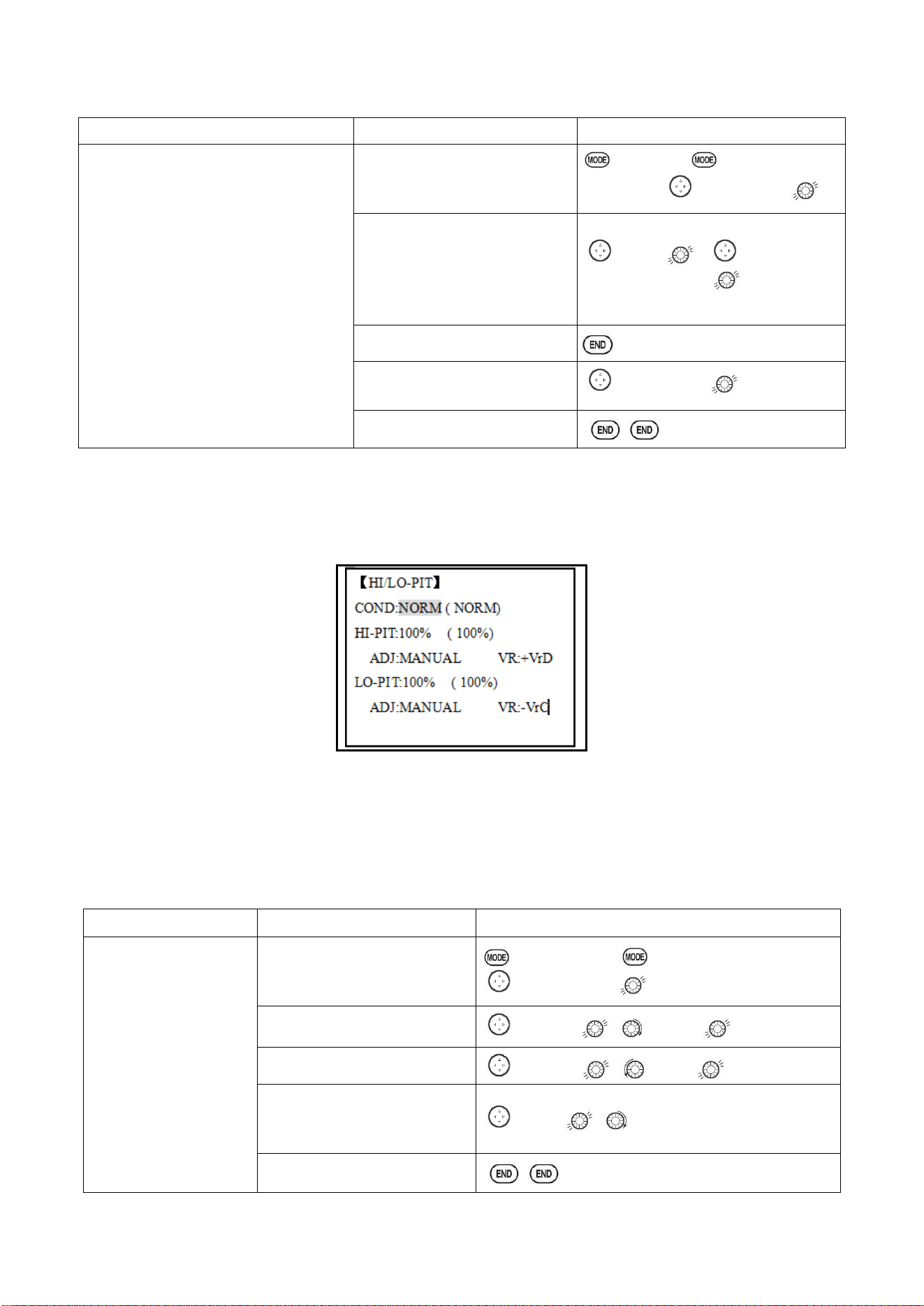
Radiolink Electronic Ltd
www.radiolink.com
74
Goals
Steps
Inputs
Fine-tune hovering with the hovering
adjustments. Remember these affect
only the hovering (normal) condition.
Adjust throttle and collective pitch
curves until model hovers nicely. In
flight,adjust collective pitch and
throttle
curves near hover point independently
with
HOV-THR
and
HOV-PIT
knobs.
Store new settings after flight.
Open the
HOV-THR
function
to BASIC. again to
ADVANCE
,
to HOV-THR.
Optional: change which
knob adjust
search hovering
curve.
NULL
locks in
curve
in last stored position.
to VR , to desired
knob and direction
Close
Open the
HOV-PIT
function.
to HOV-PIT. Repeat.
Close
5.3.6 HIGH/LOW PITCH (HI/LO-PIT):
This function may be used to adjust the curves high and low side individually for each flight
condition (normal, idle-up 1, idle-up 2, idle-up 3, throttle hold).
ADJUSTABILITY:
• You may define high and low side rate trim knobs (the high side pitch trim control is defined as the
right side lever at initial setting).
• The conditions are activated in the CONDITION SELECT function.
• Both adjustments may be set to MANUAL, temporarily turning off the knob.
• Adjustments may be memorized and then return the knobs to center point to use that amount of
adjustment, allows easy use of the trimming knobs for multiple models.
Goals
Steps
Inputs
Set up a high pitch curve
in the idle-up 1condition.
Open the HI/LO-PIT
to BASIC menu, again to ADVANCE menu.
to HI/LO-PIT.
Select the idle-up 1 condition
to COND , to IDL1
Set the rate (Ex:80%)
to HI-PIT ,
to
80%
Optional:Change which knob
adjusts high pitch curve.
to VR , to desired knob and direction.
Close
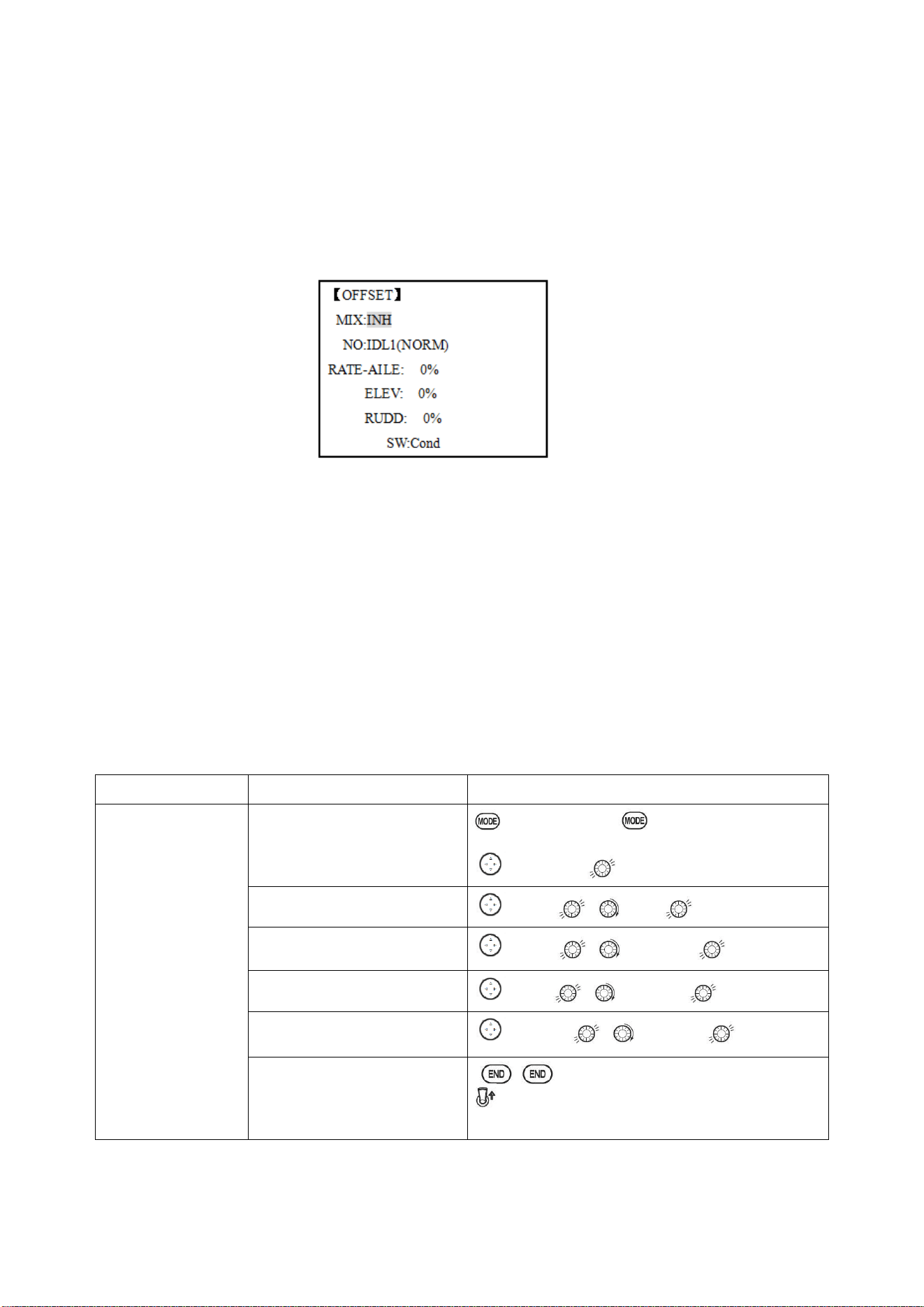
Radiolink Electronic Ltd
www.radiolink.com
75
5.3.7 OFFSET
Optional separate trims in addition to those for the normal condition. This function is used to
automatically change the trim of a helicopter, for example, when transitioned from hover to flying at
high speed. A clockwise-rotation rotor helicopter tends to drift to the right at high speed, so an
aileron offset may be applied to offset the helicopter to the left.
The necessary elevator offset varies with model geometry, so it must be determined by noting
collective pitch changes at high speed. The rudder offset is affected by both revo. mixing and trim
lever movement while in the offset function.
ADJUSTABILITY:
• Complete switch assign ability, plus a CONDITION option that creates/ switches between
individual trims for each of the idle-ups.
• When OFFSET is active (its switch is on), moving the TRIM LEVERS adjust the stored offset, not
the trims in the normal condition.
•When OFFSET is inactive (its switch is off), the OFFSET and any trim adjustments to it have no
effect (model obeys the trim settings of the currently-active flight condition.)
• When OFFSET is inhibited, trim adjustments made in any flight condition affect all flight
conditions.
• Rapid jumps caused by large offsets can be slowed using the DELAY function.
• During OFFSET operation, the aileron, elevator, and rudder travels are displayed on each trim
display in the Startup screen.
Note: Remember, offsets and revo mixes are not recommended when using heading-hold/AVCS
gyros because they conflict with the automatic corrections to trim and torque that AVCS provides.
Goals
Steps
Inputs
Set up separate
trims for each of the
three idle-up
conditions.
Adjust the idle-up
2 rudder trim to
correct for torque at
high speeds.
Open the
OFFSET
function.
to BASIC menu, again to ADVANCE
menu
to OFFSET.
Activate the function.
to MIX , to ON.
Change switch setting to
Cond
.
to SW , to Cond,
Select
IDL2
.
to NO. , to IDL2,
Adjust trim settings as needed.
(Ex:rudder to
+8%
.)
to RUDD , to +8%,
Close menus and confirm
slowed transitions.
E (AT10II) from NORMAL to IDL2.Check the
changes of rudder trim.
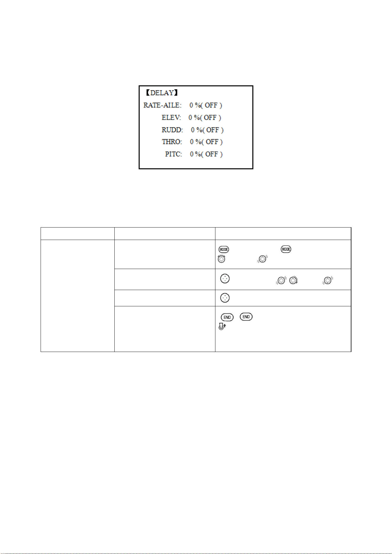
Radiolink Electronic Ltd
www.radiolink.com
76
5.3.8 DELAY:
The Delay function provides a smooth transition between the trim positions whenever OFFSET,
REVO, MIXING, or THROTTLE HOLD functions are turned on and off.
ADJUSTABILITY:
• Separate delay times are available for aileron, elevator, rudder, throttle, and pitch.
• With a 50% delay setting, the servo takes about a half-second to move to its new position, quite a
long time.
• In general, delays of approximately 10-15% are sufficient.
Goals
Steps
Inputs
Set up a delay on all
channels to ease the
transition from one flight
condition to another so
there are no ‘hard
jumps’.
Open the
DELAY
function.
to BASIC menu, again to ADVANCE
to DELAY
Adjust
AILE response
as
needed. (Ex: aileron to
+8%
.)
to RATE-AILE , to 8%,
Repeat for other channels.
to ELEV. Repeat steps above.
Close menus and confirm
slowed transitions.
E(AT10II) from NORMAL to
IDL2.Check that the servos move gradually to
new positions.
5.3.9 GOVERNORS:
The Governor mixing function is used to adjust the Governor speed settings (rS1, rS2, rS3) from
the transmitter.
What is a governor? A governor is made up of a set of sensors which read the RPM of the
helicopter’s head, and a control unit that automatically adjusts the throttle setting to maintain a
constant head speed regardless of changes in pitch of blades, weather conditions, etc. Governors
are extremely popular in competition helicopters due to the consistency provided.
How does it help in helicopter setup? The governor eliminates the need to spend large amounts of
time setting up throttle curves, as it automatically adjusts the engine’s RPM to maintain the desired
head speed.
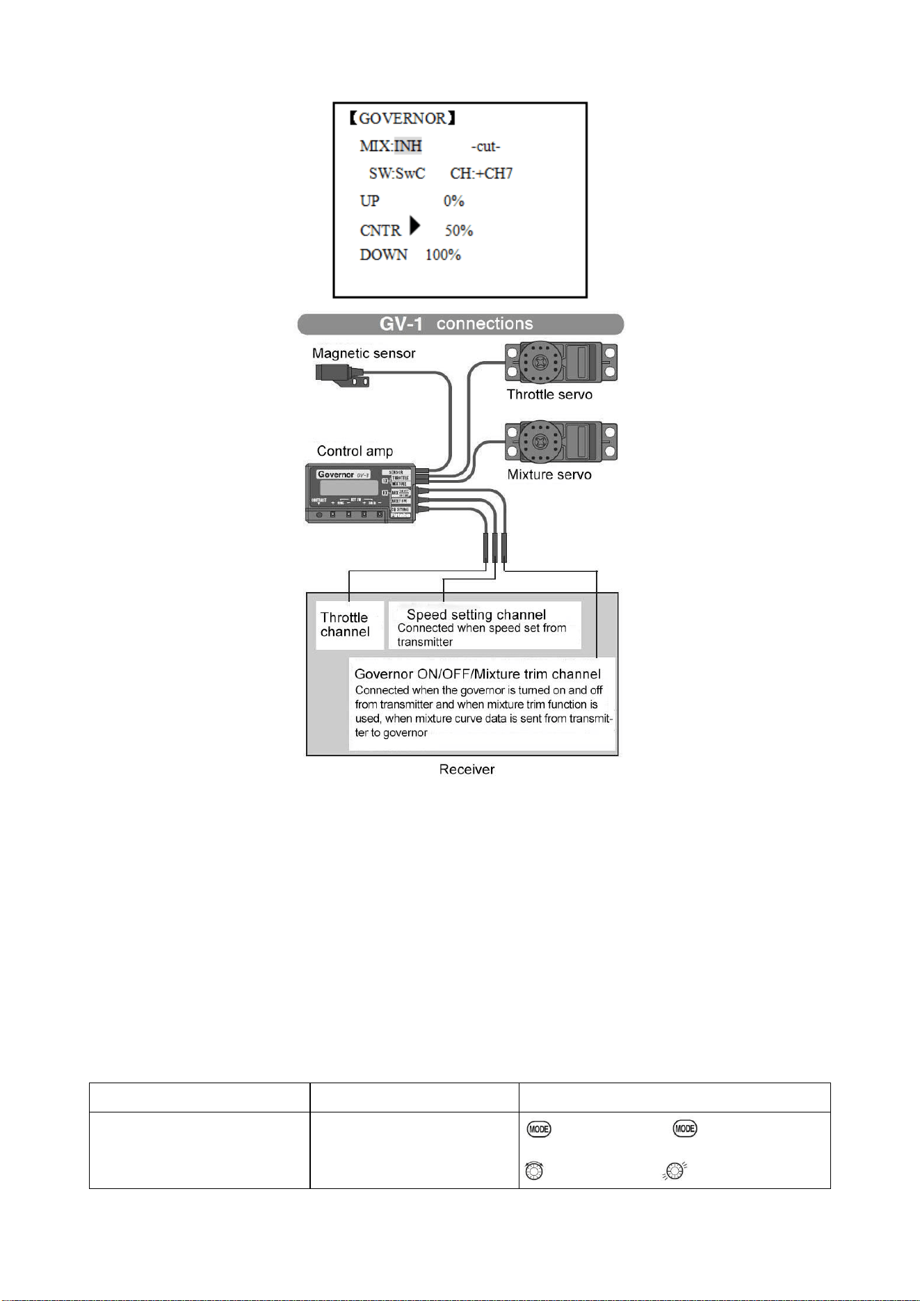
Radiolink Electronic Ltd
www.radiolink.com
77
ADJUSTABILITY:
• On/off may be separate from speed switching by plugging governor on/off into CH8 and changing
CUT-CH setting.
• If using separate on/off, switch assignment is totally adjustable. Be careful not assign governor off
to a condition switch if you want the governor to function in that condition.
• Speed switching and governor ON/OFF may be together using one switch or ON/OFF switching
may be performed using an independent switch/channel.
• When speed setting control uses CH7 and separate ON/OFF switch is not used, CH8 can be used
for other functions.
• In-flight adjustment of the head speed (for easy adjustment during turning) may be created using
an additional channel and a programmable mix.
The GV-1 controls throttle when it is active, so the throttle will not obey any Failsafe settings preset
for throttle in the transmitter. Always set the Failsafe setting for the GV-1's on/off channel to OFF.
This way the governor is shut off and the throttle obeys the Failsafe throttle commands.
Goals
Steps
Inputs
Set up a governor to use
both channels into the receiver
and switch between the
Open and activate the
GOVERNOR
Function.
to BASIC menu, again to
ADVANCE
to GOVERNOR
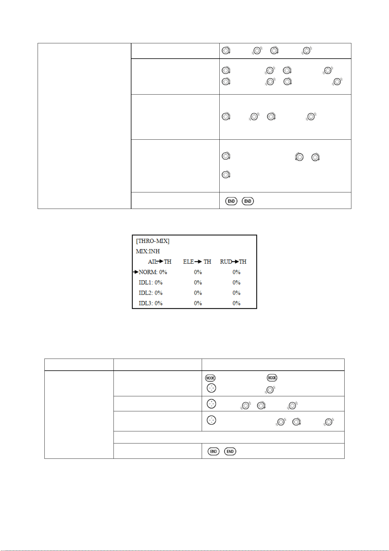
Radiolink Electronic Ltd
www.radiolink.com
78
governor settings
automatically when changing
conditions. Consider setting the
battery Fail Safe settings and
other helpful functions on the
governor itself.
Activate the function.
to MIX , to ACT.
Optional: change cut-off
channel to channel 8 and
assign switch and direction
for on/off (channel 8).
to -cut- CH: , to+CH8,
to -cut-SW , to desired SW
Optional: Changes switch
assignment to select governor
settings.
Ex: select switch that
selects the conditions.
to SW , to Cond,
Adjust governor speed
settings per switch position
or condition as needed.
(Ex: defaults are fine.)
Allows head speed
adjustment from transmitter.
to each Cond position or as
needed.
to next Cond,repeat .
Close
5.3.10 Throttle Mixing (THROTTLE MIX):
This function can be set for each flight condition, and is used to correct the tendency of the model
to change altitude when the rotor is tilted by aileron, elevator, and rudder controls.
ADJUSTABILITY:
• Mixing may be set from 0 to 100% each flight condition.
Goals
Steps
Inputs
Correct the tendency
of the model to
change altitude.
Open
THRO- MIX
function.
to BASIC menu, again to ADVANCE
to THRO-MIX
Activate the function.
to MIX , to ON
Adjust the rate.
Ex:
IDL1
(AIL to TH) 10%
to IDL1 (AIL→TH) , to 10%,
Repeat as needed.
Close
5.3.11 SWASH-RING
This function is to limit movement of swash plate to avoid damage to the SWASH ROB during
operation aileron and ELEVATOR. It is affected in 3D flight. Movement of AILERON and ELEV is
limited in the circle.
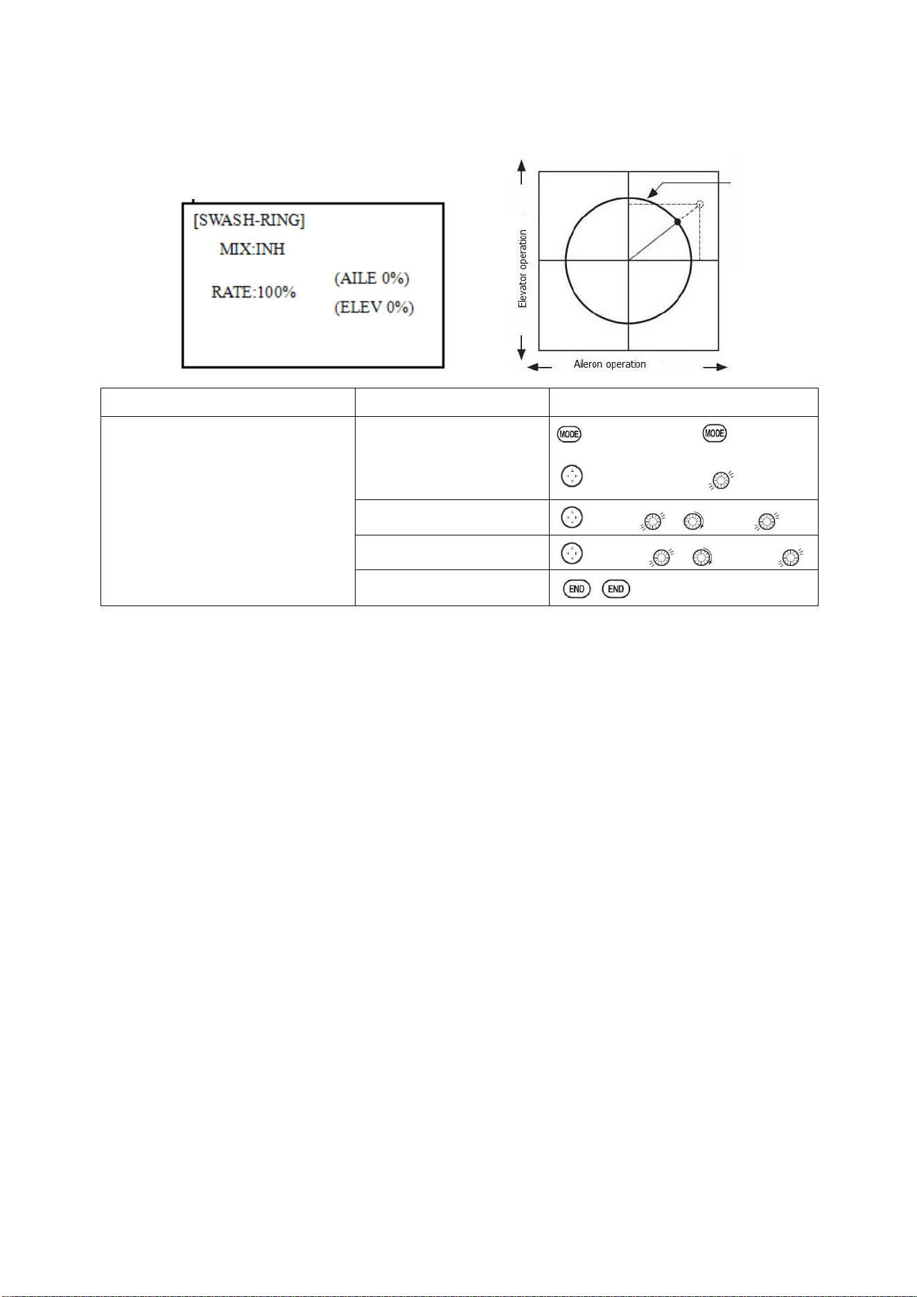
Radiolink Electronic Ltd
www.radiolink.com
79
ADJUSTABILITY:
• Initial: 100%
• adjusting range: 0-200%
5.3.12 THROTTLE NEEDLE (see ACRO MENU 3.3.15)
5.3.13 PROG MIX (see ACRO MENU 3.3.1)
5.3.14 CONDITION
Revo., curves for idle-ups are often v-shaped to provide proper rudder input with negative pitch
and increased throttle during inverted flight. (Rudder is needed to counter the reaction whenever
there is increased torque. In inverted flight, throttle stick below half has increased throttle and
negative pitch, therefore increasing torque and rotating the helicopter unless the revo. mix is also
increasing appropriately.)
Additional flight conditions are available specifically for helicopters. These additional flight
conditions contain different throttle curves, collective pitch curves, revo. mixing, and trims (except
IDLE-3) to make the helicopter perform certain maneuvers more easily. Lastly, the gyro and dual
rate functions may be set to provide separate rates per condition selected, including one for each
idle-up.
Additional idle-ups may be used to maximize the helicopter's flight characteristics in certain
types of flight (i.e. fast forward motion, backward) or maneuvers (loops, rolls, stall turns), or even
the same maneuver but changing from heading-hold/AVCS gyro mode to normal gyro mode. The
AT10II provides 3 idle-ups to allow the modeler 3 additional setups along with the normal flight
condition. (Note that IDL3 does not include governor settings.)
Goals
Steps
Inputs
To prevent damaging the swash
linkage by simultaneous operation of
the ailerons and elevators, set the
limit point where swash throw stops.
Adjust the rate at the maximum
swash tilt by simultaneous operation
of the ailerons and elevators.
Open SWASH-RING
function.
to BASIC menu, again to
ADVANCE
to SWASH-RING
Activate the function.
to MIX , to ACT
Adjust the rate Ex:
90%
to RATE , to 90%,
Close
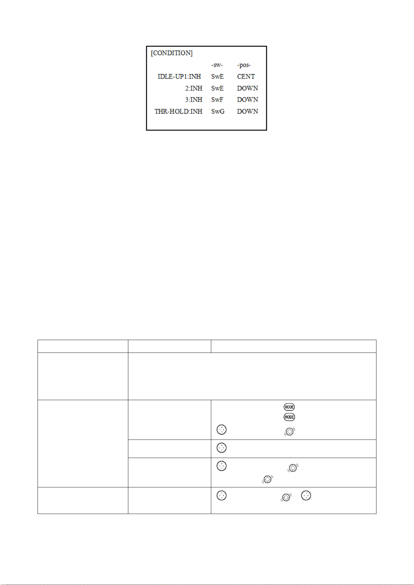
Radiolink Electronic Ltd
www.radiolink.com
80
ADJUSTABILITY:
• SWITCH G (AT10II) or E (AT10II) is programmed for normal (NORM), idle-up 1 (IDLE-UP1), and
idle-up 2 (IDLE-UP2) curves, adjustable in CONDITION SELECT (IDLE-UP1/2, IDLE-UP3 items).
(IDLE-UP1/2 3-position type switch only, IDL3 2-position type switch only)
• Activated with the throttle curve for that condition in THR-CURVE.
• Curves are adjusted to maintain constant RPM even when the collective pitch is negative
(inverted). Note that REVO mixing has one curve for idle-ups 1 and 2 and a second curve just for
idle-up3.
•Gyro settings may be set separately for each idle-up.
• Governor settings may be set up to follow Normal/Idle1/Idle2, but do not offer a setting to adjust
for each of the 5 conditions like gyro.
• Activating OFFSET makes the TRIM LEVERS adjust the trim separately in each of the idle-up
conditions.
Part 6. MULTIROTOR FUNCTIONS
MULTIROTOR menu is the most differ between AT10II and AT10. The menu makes it easier to fly
multirotor. The basic function menu is same like ACRO, GLID and HELI, please find the detail in the
former chapters.
Now let’s start the basic setting, take a quad copter for example:
Goals
Steps
Inputs
Prepare your
MULTIROTOR.
Install all servos switched, receivers, etc. per your model’s instructions. Turn on
the transmitter then receiver; adjust all linkages so surfaces are nearly centered.
Mechanically adjust all linkages as close as possible to proper control throws.
Check servo direction. Make notes now of what you will need to change during
programming
.
Select proper MODEL
TYPE.
(Ex: MULTIROTOR)
Open the BASIC menu
find the MODEL TYPE.
Turn on the transmitter, for 1 sec. to BASIC
menu (If ADVANCE, again)
to MODEL TYPE
Go to TYPE
to TYPE
Choose proper model type
(Ex: MULTIROTOR).
Confirm the change.
to MULTIROTOR, for 1 sec. ‘Are you
sure?’ Displays, to confirm.
Name the model.
Note that you do not need to
In BASIC menu, Open
MODEL SEL.
to MODEL SEL. , to NAME (the 1
st
character of model name is highlighted)
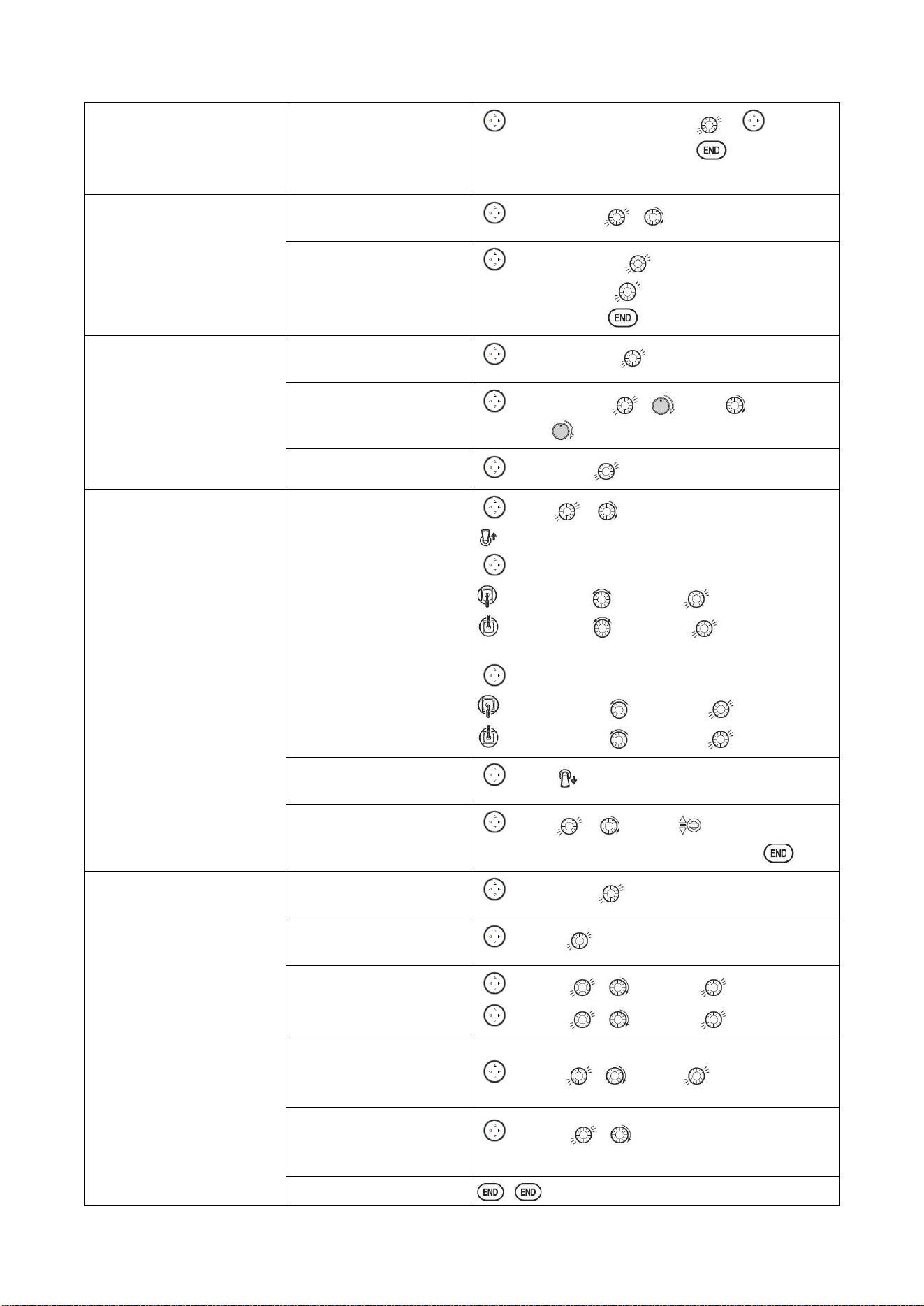
Radiolink Electronic Ltd
www.radiolink.com
81
do anything to ‘save’ or store
this data.
Input MULTIROTOR’s
name.
Close
to change the 1
st
character. . move to
next character, repeat as needed. to BASIC.
For proper control operation,
reverse servos as needed.
In the BASIC menu, open
REVERSE.
to REVERSE , to choose REV.
Choose desired servo and
reverse its direction of
travel.(Ex: reverse rudder
servo)
to CH4:RUDD , so REV highlighted, ‘Are
you sure?’ Displays.
Repeat as needed. to BASIC.
Adjust travels as needed to
match model’s recommend
throws(usually listed as high
rates)
From BASIC menu
choose END POINT.
to END POINT,
Adjust the servo’s end
points.(Ex: throttle servo)
Close
to CH1:AILE , VR(A), to desired
percentage. VR(A) to repeat above steps.
Back to choose D/R EXP.
to D/R,EXP
Set up dual/triple rates and
exponential (D/P, EXP)
(Note that in the middle of
the left side of the screen is
the name of the channel and
the switch position you are
adjusting. Two or even
THREE rates may be set per
channel by simply choosing
the desired switch and
programming percentages
with the switch in each of its
2 or 3 positions.
Choose the desired
control, and set the first
(Ex: high) rate throws and
exponential.
to CH , to CH:2 (ELEV)
SwA screen reads ELEV (UP)
to D/R
Elevator Stick to set rate.
Elevator Stick to set rate. (Normally set the
same as down.
to EXP
Elevator Stick to set rate.
Elevator Stick to set rate.
set the first (Ex: low) rate
throws and exponential.
to D/R SwA to down,repeat to set low rate.
Optional: change dual rate
switch assignment.
to SW , SwG, SwG to center
position. Repeat steps above to set 3
rd
rate.
Adjust AUX-CH and Knob.
On BASIC menu, then
open AUX-CH function.
to AUX-CH,
Choose CH5 to set
ATTITUDE
to CH5, to ATTITUDE
Assign the switch to
control attitude. Ex: SW3
is SWC,SW2 is SWB
to SW3, , to SWC,
to SW2, , to SWB,
Set the rate in each
attitude. Ex: ATTI is 50%.
to ATTI , to 50%
Change CH6, use VR (D)
to control change other
channels as needed.
to CH6 , to VR(D).
Repeat as needed.
Close
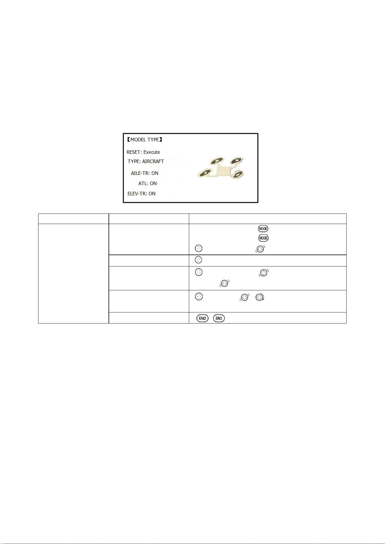
Radiolink Electronic Ltd
www.radiolink.com
82
6.1 MULTIROTOR BASIC MENU
The basic function menu is same like ACRO, GLID and HELI, please find the detail in the former
chapters. Below is the special option:
6.1.1 MODEL TYPE
Different from ACRO, GLID AND HELI, MODEL TYPE for MULTIROTOR has an additional function
TRIM, which is controlled by the VR switch. Set the TRIM OFF to avoid a mis-operation damage to
the model.
Goals
Steps
Inputs
Select proper MODEL
TYPE. (Ex:
MULTIROTOR)
Open BASIC menu, find
MODEL TYPE.
Turn on the transmitter, for 1 sec. to BASIC
menu (If ADVANCE, again)
to MODEL TYPE
Go to MODEL TYPE
to TYPE
Choose proper model type
(Ex: MULTIROTOR).
Confirm the change.
to MULTIROTOR, for 1 sec. ‘Are you sure?’
Displays, to confirm.
Turn on the trim.
to AILE-TR , to ON.
Repeat above to turn on other trims
Close
6.1.2 AUX Channel setting
AUX channel for MULTIROTOR is channel 6 to 10, same like ACRO, GLID and HELI, to set
auxiliary channel. CH5 is special for ATTITUDE, enter CH5 and press PUSH for ATTITUDE. Select
3-section and 2-section switch to get 6 different attitudes. By DIAL set 6 different rates according to
the attitudes.
6.2 ADVANCE MENU FOR MULTIROTOR
6.2.1 ATTITUDE
There are 6 different attitude modes for MULTIROTOR: NORMAL, ATTI, GPS, HOVER, F/S and
AUX. Every mode will have a different rate to get a unique signal. NORMAL mode preset 0%, ATTI
50%, GPS 100%, HOVER 25%, F/S 75% and AUX 50%.
0% means a output signal 1ms, and 100% means 2ms. You can totally get 6 different modes by
adjusting the related rates.
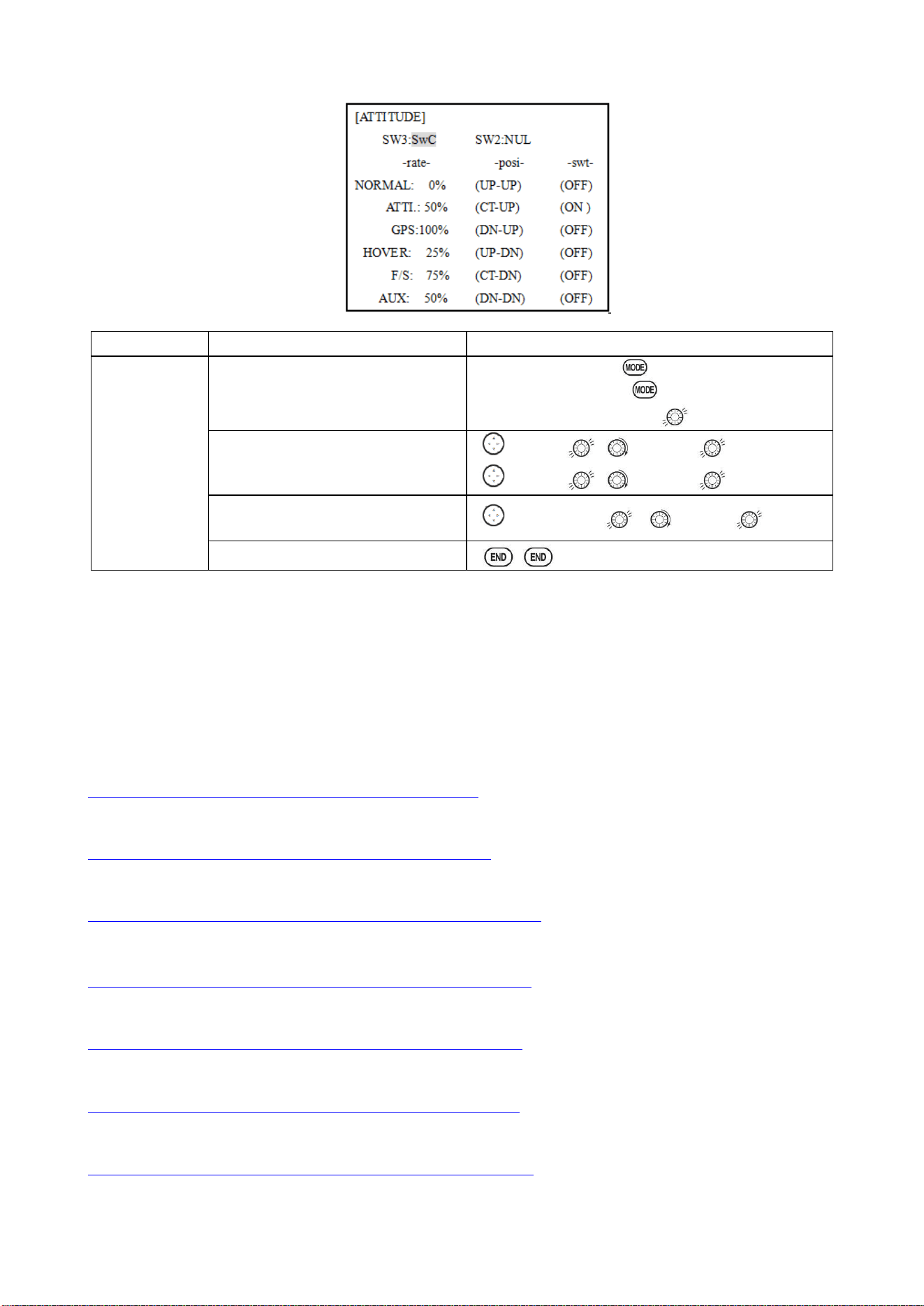
Radiolink Electronic Ltd
www.radiolink.com
83
Goals
Steps
Inputs
Set the
ATTITUDE of
MULTIROTO
R.
In ADVANCE menu find the
ATTITUDE function.
urn on the transmitter, for 1 sec. to BASIC
menu (If ADVANCE, again)
Press MODE to ATTITUDE
Assign the switch to control attitude.
Ex: SW3 is SWC,SW2 is SWB
to SW3, , to SWC,
to SW2, , to SWB,
Set the rate in each attitude.
Ex: ATTI is 60%.
to rate-ATTI, , to 60%,
Close
6.2.2 THROTTLE CURVE (see ACRO 3.3.14)
6.2.3 PROG. MIX (see ACRO 3.3.1)
AT10II Using Tutorials
RadioLink AT10 + R10D Binding
https://www.youtube.com/watch?v=rhdB6KgVsMw
RadioLink AT10 + PRM-01 Telemetry Module
https://www.youtube.com/watch?v=uWSxWrYUwAg
AT10 Firmware Upgrade
https://www.youtube.com/watch?v=SU-AclRNwWY&t=47s
RadioLink AT10 and NAZA in SBus
https://www.youtube.com/watch?v=nxU8RnwjTs4&t=372s
Mission Planner Calibration and Radiolink AT10 setup Flight Modes
https://www.youtube.com/watch?v=3jtOA4m1csA&t=26s
3 Axis CNC Gimbal with Storm32 Controlled by AT10
https://www.youtube.com/watch?v=iPna6LhoBZ8&t=19s
RADIOLINK AT10. SETUP FOR APM 2.6. APM 2.8
https://www.youtube.com/watch?v=S7DdYLgSZ7E&t=12s