
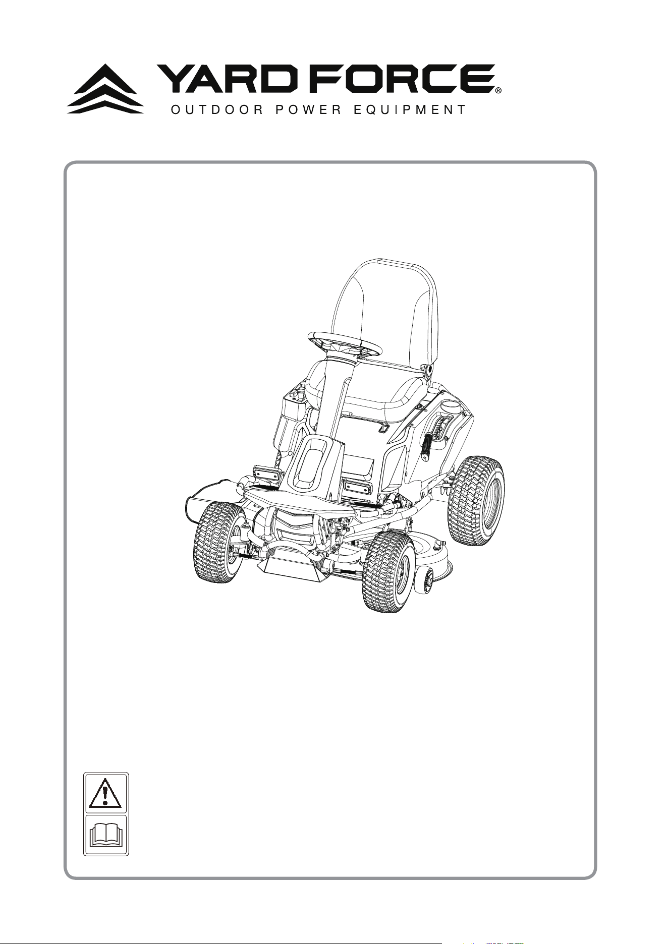
YF56vRX-RER38-Li50
YF56vRX-RER38-Li50
RIDING LAWN MOWER
OWNER'S MANUAL
Our Customer Service staff is ready to provide assistance.
In the case of a damaged or missing part, most replacement parts ship directly from Merotec
USA in Atlanta or from one of our service partners in the US & Canada.
For immediate help with assembly, or for additional product information, email support@
MerotecUSA.com. Or for the USA call 1-866-902-9690 M-F 8:30am – 5:00pm ET, for Canada
call 1-833-818-4111 M-F 8:30am - 4:30pm ET.
More information can be found on www.MerotecUSA.com.
SAVE THIS MANUAL FOR REFERENCE
You will need this manual for safety
instructions, operating procedures, and Warranty.
The original sales receipt is required for warranty service.

2
1-866-902-9690
Safety Instructions……………….........….........….........….........….........…....…....…....…....….........3
Safety Rules for Charger………….......…...........….........….........….........…....…....…....…....….........7
Description of Symbols………….......…..........….........….........….........…....…....…....…....…...........9
Parts List………….......….........….........….........….........…....…....…....…....…............…....….........11
Technical Specications……….......….........….........….........….........…....…....…....…....…............15
Assembly…………….......….........….........….........….........…....…....…....…....…............…............16
Operation………………….......….........….........….........….........…....…....…....…....…...................21
Maintenance and Storage……….......…..........….........….........….........…....…....…....…....….........29
Troubleshooting………… .......….........….........….........….........…....…....…....…....….........…........41
Warranty…………….......….........….........….........….........…....…....…....…....….................…........43
TABLE OF CONTENTS
YF56vRX-RER38-Li50 Original Instructions
3
1-866-902-9690
SAFETY INSTRUCTIONS
WARNING!
To reduce the risk of injury, the user must read and understand the operator’s manual
before using this product.
WARNING!
READ AND UNDERSTAND ALL INSTRUCTIONS. Failure to follow all instructions listed
below and on the machine could result in electric shock, re, serious personal injury
and/or death.
READ ALL INSTRUCTIONS
• This cutting machine is capable of amputating hands and feet and throwing objects. Failure to
observe all safety instructions could result in serious injury or death.
• Avoid dangerous environment — Do not use the lawn mower in damp or wet conditions or
operate in the rain.
• Keep children away — Keep all bystanders, children, and pets at least 100 ft. away. Stop the
mower and turn off the machine if anyone enters the area.
• Tragic accidents can occur if the operator is not alert to the presence of children. Children
are often attracted to the machine and the mowing activity. NEVER assume that children will
remain where you last saw them.
• Keep children out of the mowing area and in the watchful care of a responsible adult other
than the operator.
• Be alert; stop and turn machine off if a child enters the area.
• Before and while backing, look behind and down for small children, bystanders, and pets.
• Be especially careful before and when backing with the bagger kit installed, as it may limit
visibility. Always look closely behind and down for small children, bystanders, and pets, and
move the mower slowly.
• Never carry children, even with the blades shut off. They may fall off and be seriously injured
or interfere with safe machine operation. Children who have been given rides in the past may
suddenly appear in the mowing area for another ride and be run over or backed over by the
machine.
• Never allow children to operate the machine.
WARNING!
CHILDREN CAN BE KILLED OR SERIOUSLY INJURED BY THIS EQUIPMENT. The
American Academy of Pediatrics recommends that children be a minimum of 16
years of age before operating a riding lawn mower.
• Use extreme care when approaching blind corners, shrubs, trees, or other objects that may
block your view of a child.
• Dress properly — Do not wear loose clothing or jewelry. They can be caught in moving
parts. The use of rubber gloves and substantial, fully enclosed footwear with good traction is
recommended when using this mower.
• Never leave a running machine unattended. Always turn off blades, set parking pedal, turn off
the mower and remove key before dismounting.
• Check brake operation before each use and frequently during use. Adjust and service as
required.
• Keep hands and feet away from cutting area, which is located under the mower deck and
inside the side discharge chute. Keep clear of the side discharge chute opening at all times.
Do not reach under the mower deck.

4
1-866-902-9690
• Operate the lawn mower only in daylight or good articial light.
• Use safety glasses — Always wear eye protection with side shields marked to comply with
ANSI Z87.1. Use face mask if operation is dusty.
• Use the right appliance — Do not use the lawn mower for any job except that for which it is
intended.
• Do not force the lawn mower — It will do the job better and safer at the rate for which it was
designed.
• Do not charge lawn mower in rain, or in wet locations.
• Stay alert — Watch what you are doing and use common sense when operating the lawn
mower. Do not operate the mower while tired, upset, or under the inuence of drugs, alcohol,
or medication. A moment of inattention while operating the lawn mower may result in serious
personal injury.
• Maintain lawn mower with care — Keep machine in good working condition. Keep blades
sharp and guards in place and in working order. To prevent serious personal injury, damage to
the mower, and for best performance, replace damaged or unevenly worn blades.
• Check all nuts, bolts, and screws before each use for proper tightness to be sure the
equipment is in safe working condition. Mower blades are sharp. Wrap the blades or wear
gloves, and use extra caution when servicing them.
• Turn off the mower, wait until blades come to a complete stop, and remove the start key
before cleaning the lawn mower, removing the bagger, or removing the mulch cover.
• Replace blade if it is bent or cracked. An unbalanced blade causes vibration that could
damage the motor drive unit or cause personal injury. Sharpen a dull blade equally at each end
to maintain the balance. Clean the blade thoroughly and check its balance by supporting it
horizontally on a thin nail through its center hole. The nail should be in a horizontal position. If
either end of the blade rotates downward, remove some metal from the heavy lower end until
the blade is balanced. It is balanced when neither end drops.
• The side discharge chute is a spring-loaded guard that covers the side discharge opening
on the mower deck and deects grass clippings and debris away from the operator. Always
ensure that the mower is off and the blades have stopped moving before inspecting, moving,
cleaning, or performing maintenance on the side discharge chute.
• Always use safety protective devices. Do not operate the mower without the side discharge
chute in place and working properly. Mulch cover should be correctly installed and working
properly during mulching operation and bagger kit should be correctly installed and working
properly during bagging operation.
• Never interfere with the intended function of a safety device or reduce the protection provided
by a safety device. Check their proper operation regularly.
• Never tamper with safety devices. Check for proper operation regularly.
• Follow manufacturer’s instructions for proper operation and installation of accessories. Only
use accessories approved by the manufacturer. The use of other accessories may increase the
risk of injury.
• Clear the work area before each use. Remove all objects such as rocks, sticks, metal, wire,
bones, toys, fallen tree limbs, tree nuts, or other objects which can be thrown by the blade.
• Objects struck by the lawn mower blades can cause severe injuries to persons. The lawn
should always be carefully examined and cleared of all objects prior to each mowing. If the
lawn mower strikes a foreign object, follow these steps:
• Stop the lawn mower, set the parking pedal, wait until the blades come to a complete stop,
and then remove start key.
• Thoroughly inspect the mower for any damage.
SAFETY INSTRUCTIONS

5
1-866-902-9690
• Replace the blade if it is damaged in any way. Repair any damage before restarting and
continuing to operate the mower.
• Slopes are a major factor related to loss of control and tip-over accidents, which can result in
severe injury or death. Operation on all slopes requires extra caution. If you cannot back up
the slope or if you feel uneasy on it, do not mow it. Never use on steep slopes greater 15°.
• Never attempt to ride on a steep slope or mow a slope that is greater than 15°. To determine
the angle of your slope, use the Slope Guide at the back of this manual.
• Mow up and down slopes, not across.
• Watch for holes, ruts, bumps, rocks, or other hidden objects. Uneven terrain could overturn
the machine. Tall grass can hide obstacles.
• Use a slow speed so you will not have to stop suddenly or accidentally accelerate while on a
slope.
• Do not mow on wet grass. Tires may lose traction and you may lose control.
• Always keep the direction control switch in the forward position when going down slopes. Do
not shift to neutral and coast downhill, which may cause you to lose control of the mower.
• Avoid starting, stopping, or turning on a slope. If the tires lose traction, disengage the blades
and proceed slowly straight down the slope.
• Keep all movement on slopes slow and gradual. Do not make sudden changes in speed or
direction, which could cause the machine to roll over.
• Use extra care while operating machine with baggers or other attachments; they can affect the
stability of the machine. Do not use on steep slopes greater than 15°.
• Do not try to stabilize the machine by putting your foot on the ground.
• Do not mow near drop offs, ditches, or embankments. The machine could suddenly roll over
if a wheel goes over the edge or if the edge caves in and result in death or serious personal
injury.
• Never direct discharged material toward anyone. Plan your mowing pattern to avoid discharge
of material toward bystanders, roads, sidewalks, windows, cars, and the like. Also, avoid
discharging material against a wall or obstruction, which may cause the material to ricochet
back toward the operator.
• Stop the blade when crossing gravel surfaces to avoid discharging gravel and rocks and drive
the mower slowly and carefully to avoid loss of control.
• Use extra care when approaching blind corners, shrubs, trees, or other objects that may block
your view.
• Never make any adjustments or repairs with the mower on and/or blades moving. Turn off
power switch and remove key.
• Turn off the mower, set the parking pedal, wait until the blades come to a complete stop, and
remove start key before unclogging the side discharge chute or opening. The cutting blades
continue to rotate for a few seconds after the motor is shut off. Never place any part of the
body in the blade area until you are sure the blades have stopped rotating.
• If the mower should start to vibrate abnormally, turn off the mower and check immediately for
the cause. Replace the blades if they are unevenly worn or damaged in any way. Vibration is
generally a sign of a damaged mower blade.
• Disengage mower blades when not mowing.
• Service on the product and charger must be performed by qualied repair personnel only.
Service or maintenance performed by unqualied personnel could result in injury to the user or
damage to the product.
• Use only authorized replacement parts when servicing the product. Use identical replacement
SAFETY INSTRUCTIONS

6
1-866-902-9690
blades only. Use of unauthorized parts may create a risk of serious injury to the user or
damage to the product.
• Maintain or replace safety instructions labels, as necessary.
• Remove start key — Remove start key from the mower before storing, servicing, or changing
accessories such as blades. Such preventive safety measures reduce the risk of starting the
mower accidentally.
• Stop the unit and remove the start key when not in use. Transport the unit with the mower off
and the start key removed from the mower.
• Battery tools do not have to be plugged into an electrical outlet; therefore, they are always in
operating condition. Be aware of possible hazards when not using your battery tool or when
changing accessories. Following this rule will reduce the risk of electric shock, re, or serious
personal injury.
• Do not use battery-operated mower in rain.
• Remove the start key before servicing, cleaning, or removing material from the gardening
appliance.
• Store idle lawn mower indoors — When not in use, mower should be stored indoors in a dry,
locked place out of the reach of children. The start key should also be removed and stored in
a separate location out of the reach of children.
• Follow instructions for lubricating and changing accessories.
• Only allow responsible adults, who are familiar with and understand the instructions, to
operate this machine.
• Never carry passengers.
• Never operate machine in a closed area.
• Do not mow in reverse unless absolutely necessary. Always look down and behind before and
while backing.
• Slow down before turning.
• Watch for trafc when operating near or crossing roadways.
• Use extra care when loading or unloading the machine into a trailer or truck and press the
brake pedal as needed to control the speed. The mower will freely roll if it is moved on an
inclined surface without pressing the brake pedal or setting the parking pedal. When loading
or unloading the mower, do not exceed the maximum recommended operation angle of 15°.
• Data indicates operators age 60 years and above are involved in a large percentage of riding
mower related injuries. These operators should evaluate their ability to operate the riding
mower safely enough to protect themselves and others from serious injury.
• Keep machine free of grass, leaves, or other debris build up. Allow machine to cool before
storing.
• Do not spray with a garden hose to clean. Use an air moving device, such as a compressor or
leaf blower to clean the mower.
• The bagger assembly (if equipped) is subject to deterioration and wear and should be checked
each time the mower is used. If replacement is needed, make sure the new bagger meets
original manufacturer’s recommendations and specications.
ADDITIONAL SAFETY RULES FOR BATTERIES
Do not open or mutilate the batteries. Released electrolyte is corrosive and may cause damage to
the eyes or skin. It may be toxic if swallowed.
• Do not dispose of the batteries in a re. The batteries could explode. Check with local codes
SAFETY INSTRUCTIONS

7
1-866-902-9690
for possible special disposal instructions.
• When batteries are not in use, keep away from other metal objects like paper clips, coins,
keys, nails, screws, or other small metal objects that can make a connection from one terminal
to another. Shorting the battery terminals together may cause serious burns or a re.
• Exercise care in handling batteries in order not to short the battery with conducting materials
such as rings, bracelets, and keys. The battery or conductor may overheat and cause burns.
• Under extreme usage or temperature conditions, battery leakage may occur. If liquid comes
in contact with your skin, wash immediately with soap and water. If liquid gets into your eyes,
ush them with clean water for at least 10 minutes, then seek immediate medical attention.
Following this rule will reduce the risk of serious personal injury.
• Do not charge battery in an area of extreme heat or cold. Batteries will charge best at
temperatures from 41˚F to 104˚F.
• Only use YARD FORCE Electric Riding Lawn Mower 50Ah Li-ion battery (Part number:
1004554000).
ADDITIONAL SAFETY RULES FOR TOWING
• Use common sense when towing. Too heavy of a load while on a slope is dangerous. Tires can
lose traction with the ground and cause you to lose control of your mower.
• Follow manufacturer’s recommendations for wheel weights or counterweights.
• Total towed weight must not exceed the weight that you can safely control with the mower.
• Do not attach towed equipment except at the approved hitch point.
• Never allow children or others in or on towed equipment.
• Stopping distance increases with speed and weight of load being towed. Travel slowly and
allow extra time and distance to stop.
• Do not turn sharply when towing. Use additional caution when turning or operating under
adverse surface conditions. Use care when reversing.
1. SAVE THESE INSTRUCTIONS - DANGER - TO REDUCE RISK OF FIRE OR ELECTRIC
SHOCK, CAREFULLY FOLLOW THESE INSTRUCTIONS. This manual contains important
safety and operating instructions for battery charger WTL5608PNG.
2. Before using battery charger, read all instructions and cautionary markings on battery charger,
battery, and product using battery.
CAUTION!
To reduce the risk of injury, charge only YARD FORCE Electric Riding Lawn Mower 50 Ah
lithium iron phosphate battery. Other types of batteries may burst, causing personal injury
or damage.
DANGER!
TO REDUCE THE RISK OF FIRE, ELECTRIC SHOCK, DEATH, OR SERIOUS PERSONAL
INJURY, CAREFULLY FOLLOW THESE INSTRUCTIONS.
• This manual contains important safety and operating instructions for the charger. Refer to them
frequently and use them to instruct others who may use this product. If you loan someone
this product, loan them these instructions also to prevent misuse of the product and possible
injury.
• Before using the charger, read and understand all instructions and cautionary markings in this
SAFETY RULES FOR CHARGER
SAFETY INSTRUCTIONS
8
1-866-902-9690
manual, on battery charger, batteries, and 56V mower to prevent misuse of the products and
possible injury or damage.
• This charger is to be used only for charging this 56V mower. Use with other products or
batteries may cause personal injury as well as damage to the product or charger.
• The charger is not meant for use by children.
• Provide adequate ventilation for the charger to dissipate heat during charging. The charger will
get hot. Keep away from ammable and combustible material and do not cover the charger.
• Risk of Burn Hazard — Charger surfaces may be hot during operation. Use the charger handle
only. Mount charger on a table or wall with the cooling ns vertical.
• Risk of electric shock. Do not touch uninsulated portion of output connector or uninsulated
battery terminal.
• Do not use charger outdoors or expose to wet or damp conditions. Water entering charger
will increase the risk of electric shock. The charger must be plugged into a Class A GFCI
receptacle when used outdoors.
• Keep charger and charger plug free of contamination and dirt. Do not let gasoline, oils,
petroleum-based products, etc. come in contact with plastic parts. They contain chemicals
that can damage, weaken, or destroy plastic.
• Keep cord and charger away from heat to prevent damage to housing or internal parts.
• Do not operate charger with a damaged cord or plug, which could cause shorting and electric
shock. If damaged, have the charger replaced by an authorized service person.
• Do not operate charger if it has received a sharp blow, been dropped, or otherwise damaged
in any way. Take it to an authorized service person for electrical check to determine if the
charger is in good working order.
• Make sure cords are located so that they will not be stepped on, tripped over, come in contact
with sharp edges or moving parts, or otherwise subjected to damage or stress. This will
reduce the risk of accidental falls, which could cause injury, and damage to the cords, which
could result in electric shock.
• An extension cord should not be used unless absolutely necessary. Use of improper extension
cord could result in a risk of re and electric shock. If extension cord must be used, make
sure:
a. That pins on plug of extension cord are the same number, size, and shape as those of plug
on charger.
b. That extension cord is undamaged and in good electrical condition; and
c. That wire size is large enough for AC ampere rating of charger as specied below:
Cord Length (Feet) 25' 50' 100'
Cord Size (AWG) 14 14 12
NOTE: AWG = American Wire Gauge
• Do not disassemble charger. Opening the charger will void its warranty. If charger requires
service or repair during the warranty period, take it to an authorized service center to be
replaced.
• Service person must unplug charger from the AC wall outlet and from the mower charge port
before attempting any maintenance or cleaning to reduce the risk of electric shock.
SAFETY RULES FOR CHARGER
9
1-866-902-9690
The following symbols are used on the product and in this manual to alert the operator of potential
safety hazards. Read them carefully, and understand their meaning.
DANGER!
Indicates an imminently hazardous situation which, if not avoided, will result in death or
serious injury.
WARNING!
Indicates a potentially hazardous situation which, if not avoided, could result in death or
serious injury.
CAUTION!
Indicates a potentially hazardous situation which, if not avoided, may result in minor/
moderate injury.
NOTICE!
Indicates a practice not related to personal injury which, if not avoided, may result in
property damage.
Other Symbols
Some of the following symbols may be used on this product. Please study them and learn their
meaning. Proper interpretation of these symbols will allow you to operate the product better and
safer.
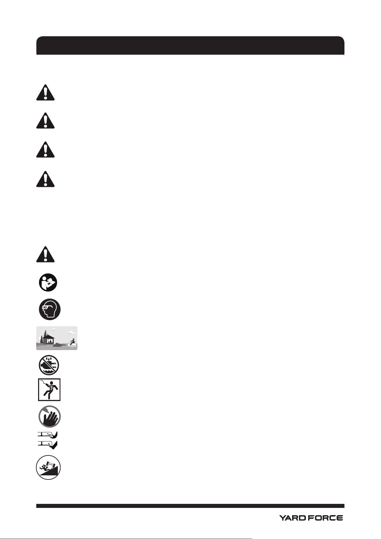
Look for this symbol to point out important safety precautions. It means: Attention!
Become Alert! Your Safety Is Involved.
Read operator’s manual before operating this machine. Failure to follow directions could
result in serious injury.
Wear eye protection complying with ANSI Z78.1 and hearing protection.
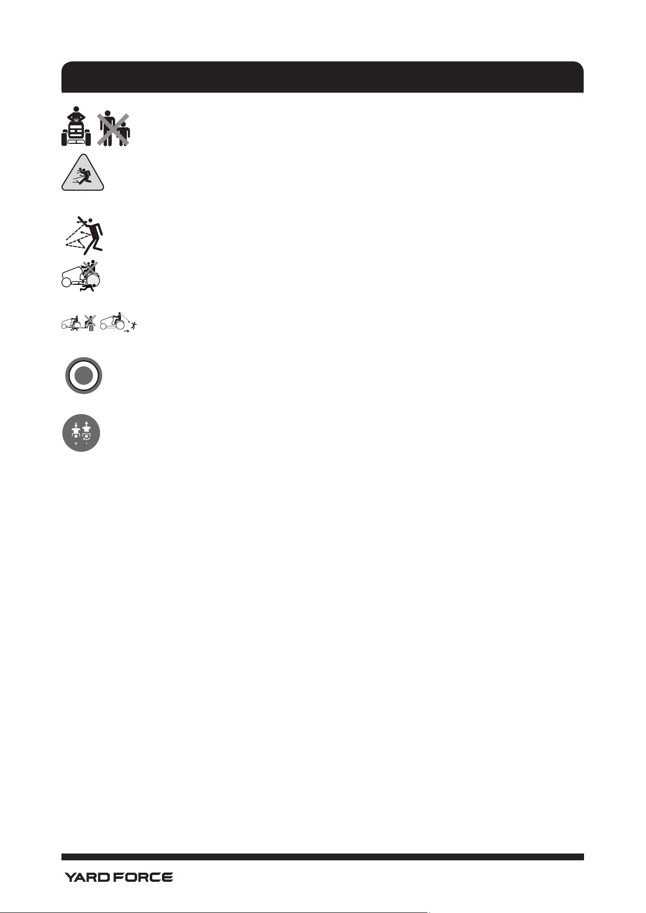
Keep children out of the mowing area and in the watchful care of a responsible
adult other than the operator.
Wet Conditions Alert. Do not expose to rain or use in damp locations.
Failure to use in dry conditions and to observe safe practices can result in electric shock.
Keep hands and feet away from blade and cutting area.
Do not reach hands or feet under mower deck.
Do not operate on steep slopes or inclines greater than 15º. Mow up and down the face
of slopes, never across.
DESCRIPTION OF SYMBOLS
Keep children safe
and away from mower.
Supervise Children!
10
1-866-902-9690
Keep all children, bystanders, and animals at least 100 ft. away.
Thrown objects can ricochet and result in personal injury or property damage.
Thrown objects can ricochet and result in personal injury or property damage. Never
direct discharged material toward anyone.
Never carry children or anyone, even when the blades are off.
Always look down and behind you before and during backing and make sure
children, bystanders, and pets are clear of the area.
Mower can be operated in reverse with blades engaged when RMO button is pushed and
red button light is on. Always look down and behind you before and when manuevering in
reverse. Mowing in reverse is not recommended
Lift the blade engagement button up to engage. Press the blade engagement button
down to disengage.
DESCRIPTION OF SYMBOLS
11
1-866-902-9690
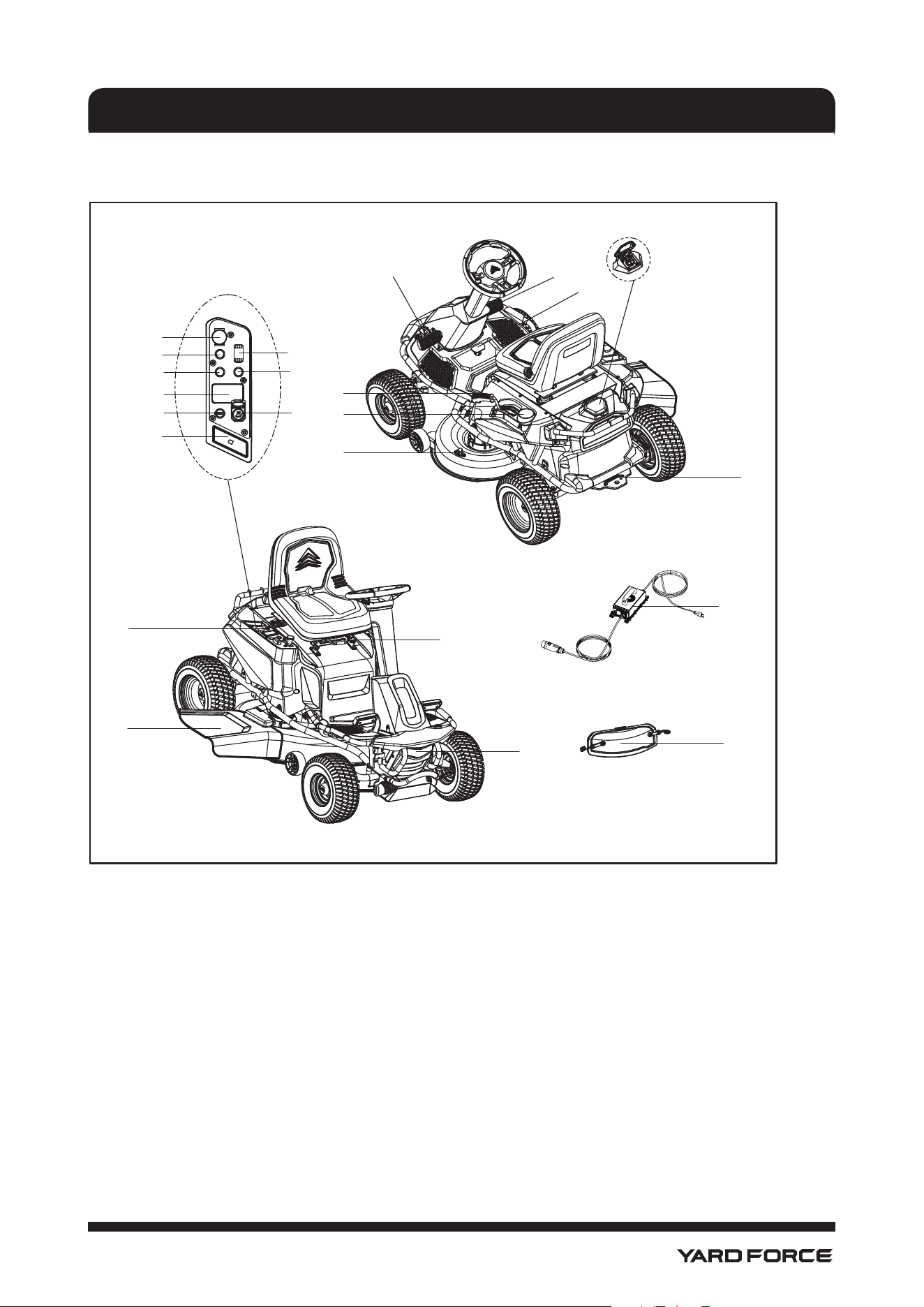
KNOW YOUR LAWN MOWER (See Fig.1)
PARTS LIST
1. Brake Pedal
2. Accelerator Pedal
3. Parking Pedal
4. Charging Port
5. Hitch Point
6. Wash Port
7. Cup Holder
8. Deck Height Adjustment Lever
9. Seat Adjustment Lever
10. Headlight
11. Side Discharge Chute
12. Control Pannel
12a. Media Holder
12b. Power Switch with Start Key
12c. Headlight Button
12d. Reverse Mode Button
12e. Blade Engage Knob
12f. Direction Control Switch
F= Forward
N=Neutral
R=Reverse
12g. Cruise Control Button (CCS)
12h. Battery Level Indicator/
Odometer/Parking Brake Indicator
12i. USB Port
13. Mulch Cover
14. Charger
1
12f
12e
12c
12d
12h
12b
12a
12
9
10
13
14
11
12g
12i
2
3
4
5
8
7
6
Fig. 1

12
1-866-902-9690
The safe use of this product requires an understanding of the information on the product and in this
operator’s manual as well as a knowledge of the project you are attempting. Before use of this product,
familiarize yourself with all operating features and safety rules.
• ACCELERATOR PEDAL
The accelerator pedal controls the speed of the mower.
• BATTERY LEVEL INDICATOR/ODOMETER/PARKING BRAKE INDICATOR
The battery level indicator shows the amount of battery charge remaining. The parking brake indicator
shows if the brakes are applied. The odometer tracks the total distance the mower has been used (key
in on position) for maintenance purposes.
• BLADE ENGAGE KNOB
Pull the blade engage knob up to activate the mower’s cutting blades. Push the knob down to stop the
cutting blades.
NOTE: For cutting in reverse, the reverse mode button must also be activated.
• BRAKE PEDAL
The brake pedal is used for slowing down and stopping the mower.
• CHARGER
The mower’s charger has a eyelets for convenient mounting or space saving storage. When mounting
the charger, use screws in both holes of the mounting ange to secure in place. Always mount in such a
way that the charger’s LED status light is visible while charging.
• CRUISE CONTROL BUTTON (CCS)
The cruise control button allows you to continue forward at a set speed without needing to press the
accelerator pedal. While active, pressing the brake pedal, accelerator pedal or CCS button will interrupt
cruise control.
• DECK HEIGHT ADJUSTMENT LEVER
The deck height adjustment lever is used to raise or lower the cutting deck.
• DIRECTION CONTROL SWITCH
The direction of movement of the mower is controlled using the direction control switch. Available
settings are forward (F), neutral (N) and reverse (R).
• HEADLIGHT BUTTON
Turn the headlights on and off using the headlight button.
• MEDIA HOLDER
The media holder offers a convenient place to store your cell phone or MP3 player when charging with
the USB port.
• MULCH COVER
Your mower is equipped with a mulch cover that covers the side discharge opening, which allows the
mower blade to cut and recut for ner clippings.
• PARKING PEDAL
Use the parking pedal to lock the mower in the braked position. Brake pedal must be depressed before
the parking pedal will lock.
• POWER SWITCH WITH START KEY
The power switch is used to turn the mower on and off. The start key must be inserted before the switch
can be operated.
• REVERSE MODE BUTTON
Press the reverse mode button to allow the mower to cut when maneuvering in the reverse direction.
The blades will disengage if mower is operated in reverse without rst pressing the reverse mode
button. Once the button is engaged the mower will remain in both reverse and forward mowing mode
until the button is pressed again or the blades are disengaged. NOTE: The blade engage knob must also
be pulled up for mowing to occur when driving in reverse.
• SEAT ADJUSTMENT LEVER
Use the seat adjustment lever to move the seat to the desired position.
• USB PORT
The USB charging port provides charging power of 5 Volts DC at up to 2 amps for your cell phone,
MP3 player, or other USB devices. Consult the owner’s manual for your device for specic charging
requirements. Connect one end of a USB cable (not provided) to your device and the other end to the
USB charging port on the mower, to begin charging your device.
PARTS LIST
13
1-866-902-9690
NOTE: The USB port is only powered when the start key is in the ON position.
NOTICE!
Attempting to charge devices rated more than 2 amps could damage the USB charging port and/or
the mower.
WARNING!
Never use headphones or any electronic device, such as a smart phone or tablet, while operating
the mower. Distracted operation can result in an accident that could result in death or serious
personal injury to the operator or a bystander.
WARNING!
If any parts are damaged or missing, do not operate this lawn mower until the missing parts are
replaced. Failure to heed this warning could result in serious personal injury.
NOTICE!
Always recycle the packaging in accordance with local recycling programs.
WARNING!
This item requires a two-person lift to remove from the packaging. Make sure that you have sufcient
space to put the lawn mower down. Keep your feet apart so that you have a stable position, bend at
the knees and keep your back straight.
PARTS LIST
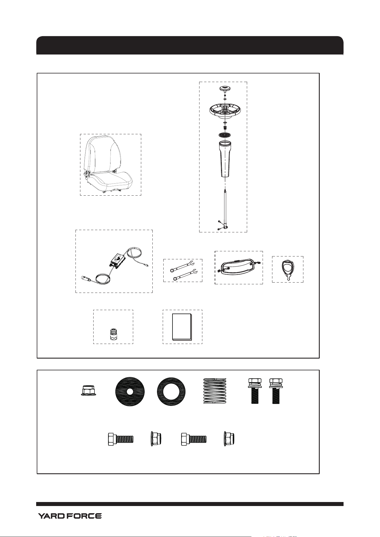
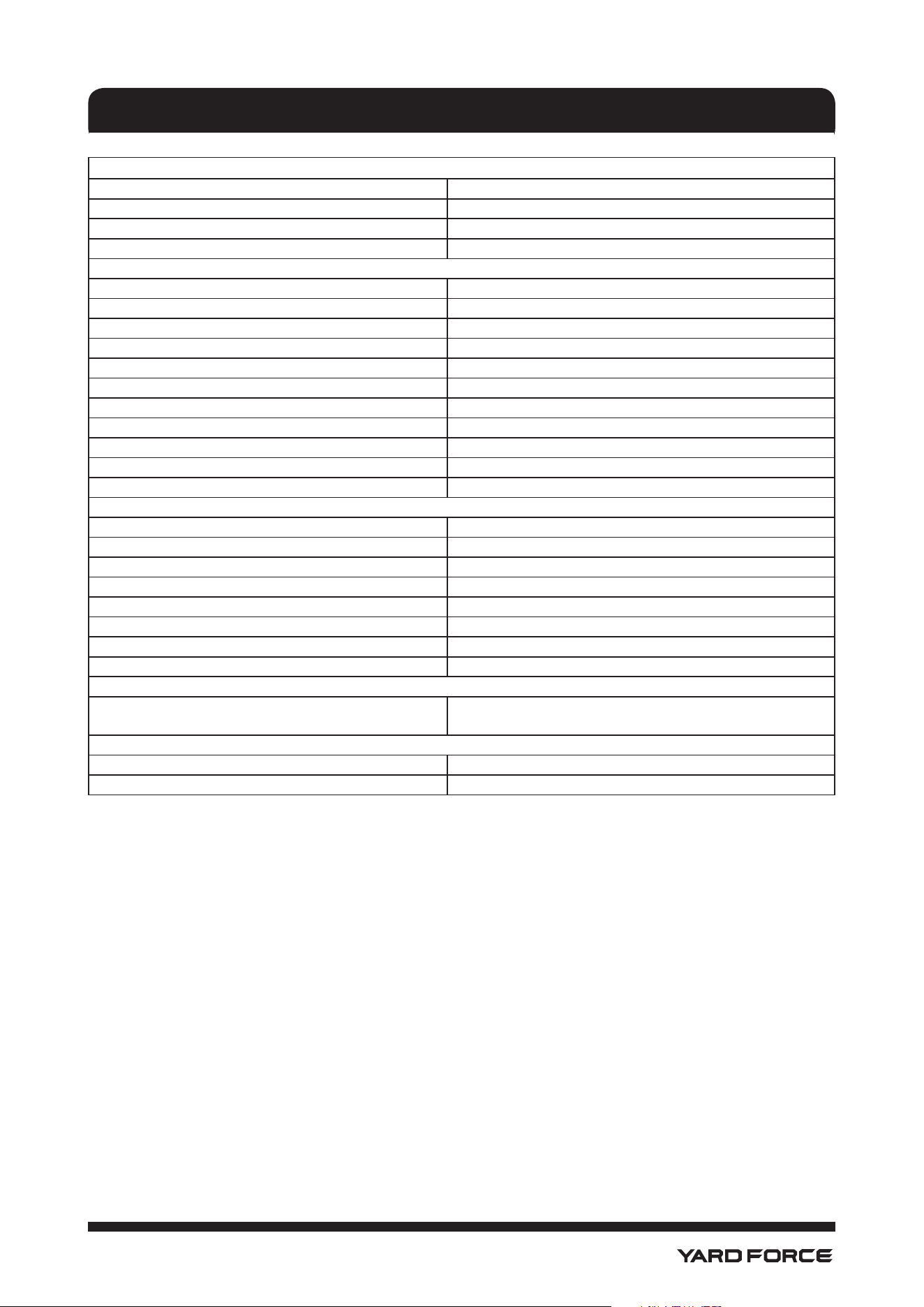
Carefully remove all parts from their packaging and check that the following parts are included. See Fig 2 &
Fig. 2A:
A. Seat Assembly with Safety Interlock Cable 1pc
Flange Nut (A) 2pcs
Bolt (B) 2pcs
B. Steering Column Assembly
Spring (C) 1pc
Washer (D) 1pc
Washer (E) 1pc
Flange Nut (F) 1pc
Bolt (G) 2pcs
Spring Washer (H) 2pcs
Washer (I) 2pcs
Upper Steering Shaft 1pc
Steering Column 1pc
Steering Column Cover 1pc
Steering Wheel 1pc
Steering Wheel Cover 1pc
C. Charger 1pc
D. Wrenches 2pcs
E. Mulch Cover 1pc
F. Key 3pcs
G. Wash-port Quick Coupler 1pc
H. Owner’s Manual 1pc
PARTS LIST
14
1-866-902-9690
PARTS LIST
Fig. 2
A
C
D
E
F
HG
B
MANUAL
Fig. 2a
Flange Nut (A) Washer (E) Washer (D) Spring (C) Bolt (G),
Spring Washer (H),
Washer (I)
Flange Nut (A)Bolt (B)
Flange Nut (A)Bolt (B)
Note: Both Flange Nuts (A) and Bolt (B) are attached to seat for shipment.
15
1-866-902-9690
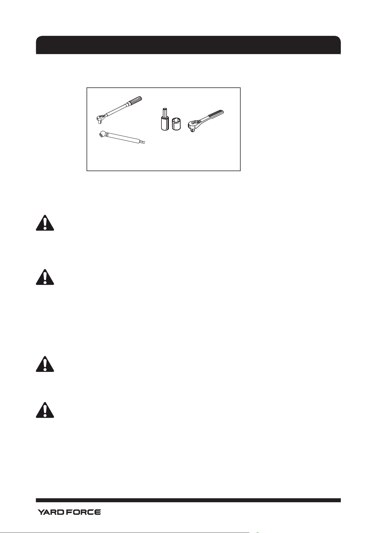
Dimension
Assembled Length 63.5" (1610mm)
Assembled Height 45.5" (1155mm)
Assembled Width Without Discharge Deector 38" (960mm)
Net Weight 463 lb (210 kg)
Mower & Deck
Pneumatic Tire Sizes 15" x 6" x 6" Front, 16" x 6.5" x 8" Rear
Cutting Width 38" (96cm)
Blade Cutting Diameter 19" (49cm)
Number Of Blades 2
Number Of Deck Wheels 2
Cold Tire Pressure 20 PSI (138 kPa)
Blade Speed 3500 rpm
Deck Lift System Hand operation
Minimum Cutting Height 1.5" (38mm)
Maximum Cutting Height 4.5" (114mm)
Number of Cutting Height Positions 12
Battery
Battery Type Li-ion (LFP)
Battery Voltage(V) 51.2
Battery Amp Hours (Ah) 50
Charge Time (hours) 8
Number of Batteries 1
Charge Cycle 3000~4000
Charger and Mower Operating Temperatures 32°F~104°F
Charger and Mower Storage Temperatures -4°F ~ 131°F (-20°C-55°C)
Charger
Type
Input:100~240V,50~60HZ, Max. 5A;
Output: 57.6V DC,8A
Performance
Maximum Forward Speed 8 mph(12.9 km/h); 5 mph (mow, 8 km/h)
Maximum Reverse Speed 3 mph (4.8 km/h)
PRODUCT SPECIFICATIONS
16
1-866-902-9690
ASSEMBLY
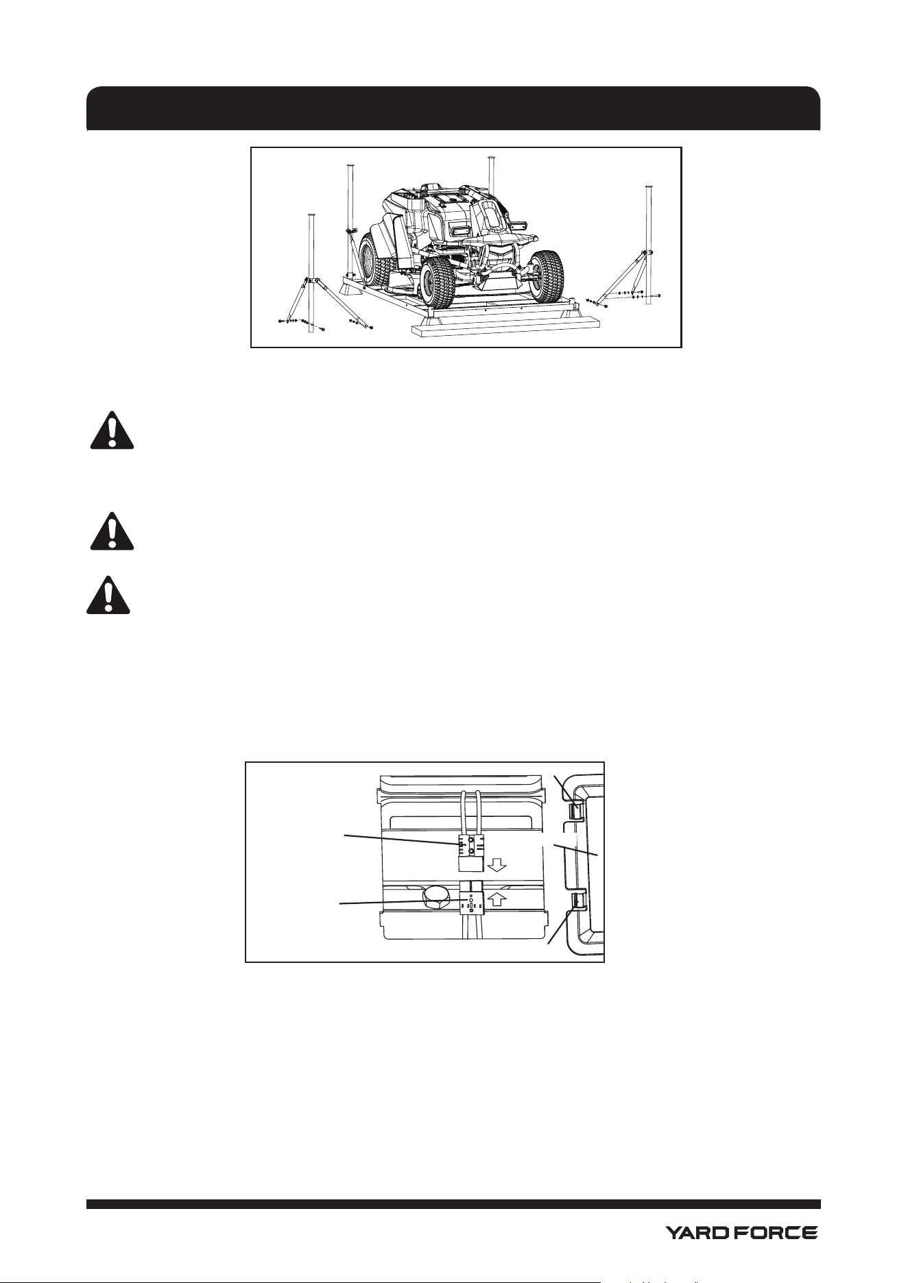
TOOLS NEEDED
The following tools (not included or drawn to scale) are needed for assembly:(See Fig. 3)
UNPACKING (See Fig. 4)
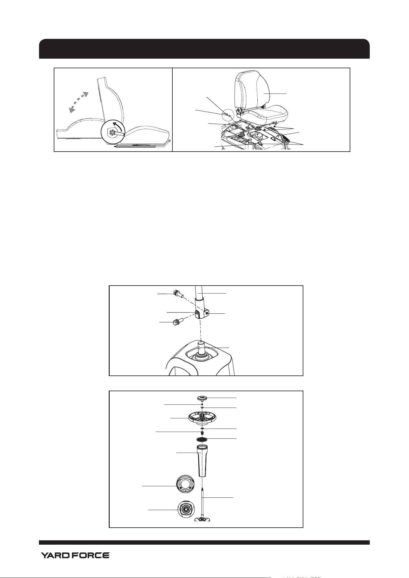
• Remove the hardware securing the corner and side braces to the frame bottom, then lift the braces to
remove.
WARNING!
Do not discard the hardware to avoid any personal injury.
• Cut the nylon straps securing the front and rear wheel axles to the frame.
• Remove and set aside all accessible packaging and wrap from unit and parts. Do not discard the
packing material until you have carefully inspected and satisfactorily operated the product.
WARNING!
If any parts on the Parts List are already assembled to your product when you unpack it, verify the
parts are assembled correctly, are properly tightened, and are torqued correctly (where applicable)
before proceeding to the next assembly step. Use of a product that may have been improperly
assembled could result in serious personal injury.
• Inspect the product carefully to make sure no breakage or damage occurred during shipping.
• If any parts are damaged or missing, please call Yard Force customer service at 1-866-902-9690 (US),
or 1-833-818-4111 (CA).
NOTE: Mower should be assembled while positioned on the frame bottom. Once assembly is complete,
raise the cutting deck to its highest position. Position a board such as a standard 2"x4" along the front of
the pallet to create a gradual transition between the frame and the ground. Slowly drive the mower forward.
WARNING!
Use care when driving the mower off of the frame and press the brake pedal as needed to
control the speed. The mower will freely roll if it is moved on an inclined surface without
pressing the brake pedal or setting the parking brake. Failure to follow these instructions
can result in loss of control and result in death, serious personal injury, or property damage.
NOTICE!
Driving the mower off the frame in the forward direction without a transition board can
cause damage to the mower’s cutting deck.
Torque Wrench
Tire Pressure Gauge
20
30
40
0
50
Socket Wrench with 12 mm, 13 mm,
and 14 mm sockets And 6mm Hex Bit
Fig. 3
17
1-866-902-9690
ASSEMBLY
ASSEMBLY
WARNING!
Strictly adhere to all torque wrench tightening specications. Failure to do so could cause
serious personal injury.
WARNING!
Do not attempt to modify this product or create accessories not recommended for use with
this product. Any such alteration or modication is misuse and could result in a hazardous
condition leading to possible serious personal injury.
WARNING!
To prevent accidental starting that could cause serious personal injury, always remove the
start key from the tool when you are assembling parts.
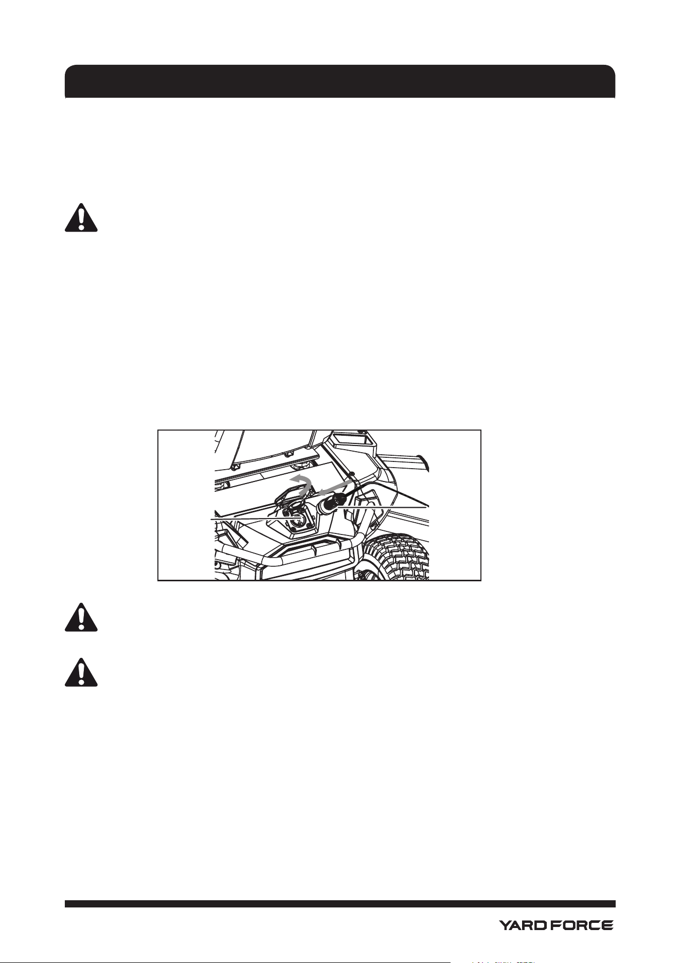
CONNECT THE BATTERY (See Fig. 5)
When shipped from the factory, the mower’s batteries are disconnected. To connect:
• Press the tabs on the wiring cover and lift the cover to remove.
• Connect the two ends of the battery quick-connect plug together.
NOTE: Before reinstalling the wiring cover, install the seat as described in the next section.
INSTALL THE SEAT (See Fig. 6)
• Put the seat on a at ground, Kneel on the seat and hold the back of the seat with one hand, rotate
the adjusting handle upward with another hand to set the seat back to vertical position ,release the
adjusting handle to lock the position.
• Remove ange nuts (A) and bolts (B) from seat mounting brackets.
• Place the seat assembly over the mounting brackets and align holes as shown.
• Reinstall ange nuts (A) and bolts (B) and tighten securely.
• Route seat safety interlock cable through hole in wiring cover, then attach to plug on mower.
• Reinstall wiring cover and make sure it is securely seated.
Fig. 5
Tab
Tab
Battery Quick-
connect Plug
Battery Quick-
connect Plug
Wiring Cover
Fig. 4
18
1-866-902-9690
ASSEMBLE THE STEERING COLUMN (See Fig. 7&8)
• Install the upper steering shaft onto the lower steering shaft, rotate as needed to align the holes in both
shafts.
• Install washers (I), spring washers (H), bolts (G) and tighten securely. Torque to 6 ft.lbs.
• Insert steering column over shaft. Note the tabs on the bottom of the steering column that t into the
holes in the opening and make sure steering column is securely seated.
• Align the groove on the steering column cover with the top of the steering column then install the
steering column cover. The upper steering shaft will protrude through the opening in the cover.
• Install spring (C) and washer (D) onto the upper steering shaft.
• Make sure the mower's wheels are pointed straight ahead, then install the steering wheel onto the upper
steering shaft.
• Install washer (E) and ange nut (A), tighten securely, Torque nut to 6ft.lbs.
• Install the steering wheel cover.
ASSEMBLY
Fig. 7
Bolt (G)
Bolt (G)
Bolt Hole
Lower Steering Shaft
Bolt Hole
Upper Steering Shaft
Fig. 8
Steering Wheel Cover
Flange Nut (A)
Spring (C)
Tab
Hole
Washer (E)
Steering Wheel
Washer (D)
Steering Column Cover
Steering Column
Upper Steering Shaft
Fig. 6
Seat Asembly
Wiring Cover
Safety Interlock
Cable
Plug
Flange Nut (A)
Bolt (B)
Bolt (B)
Mounting Bracket
19
1-866-902-9690
FINAL PREPARATION
CHECK TIRE PRESSURE
Check the air pressure in all tires before use. Improper air pressure will affect handling, steering response,
traction, tire life, level cutting, and operator comfort. Be sure tires are inated to the pressure shown below.
NOTE: Tire pressure should only be measured or adjusted when tires are cold.
Recommended Pressure: 20 PSI (137 kPa)
WARNING!
Check the tire pressure carefully while inating. Too much air in the tire could cause the tire to burst,
causing serious personal injury.
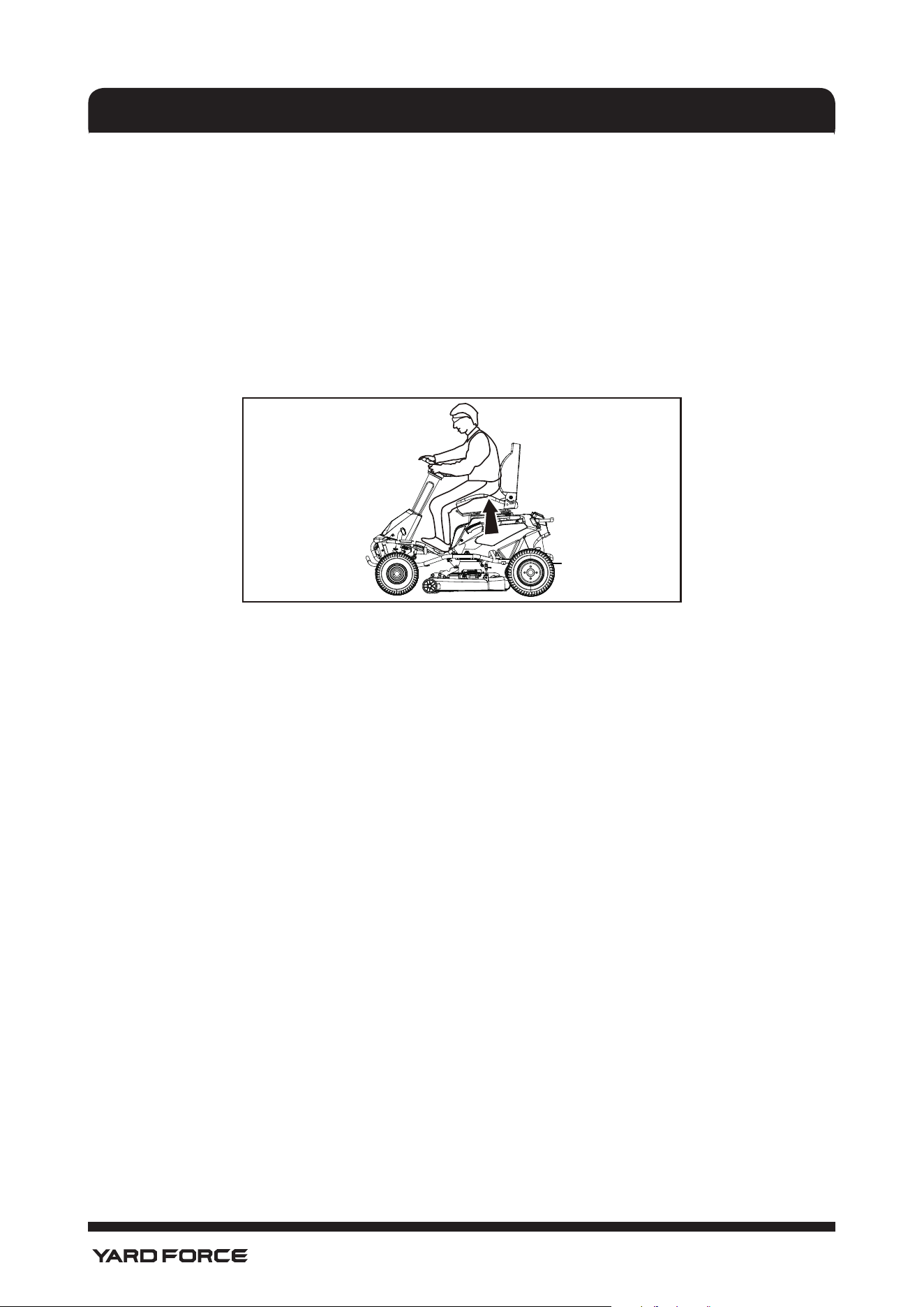
CHARGE THE MOWER (See Fig.9.)
Mower batteries must be fully charged before rst use. To verify mower batteries are fully charged, check
the battery level indicator. It is recommended the batteries are charged for minimum 4 hours before rst use
regardless of battery level indicator reading 100% charge.
To charge:
Turn the key to OFF position.
Insert charger plug into charging port on mower, making sure it is properly connected.
Connect charger to power supply using normal household current of 120 V, AC only, 60 Hz.
Do not charge in an area of extreme heat or cold.
Remove the charger from the mower once it is fully charged and ready for use.
WARNING!
To avoid accidental starting or movement of the mower that could result in serious personal injury,
always remove the start key and set the parking pedal when leaving the mower unattended.
NOTICE!
Make sure to charge the batteries fully at least once a month.
ASSEMBLY
Fig. 9
Charger
Plug
Charging
Port
20
1-866-902-9690
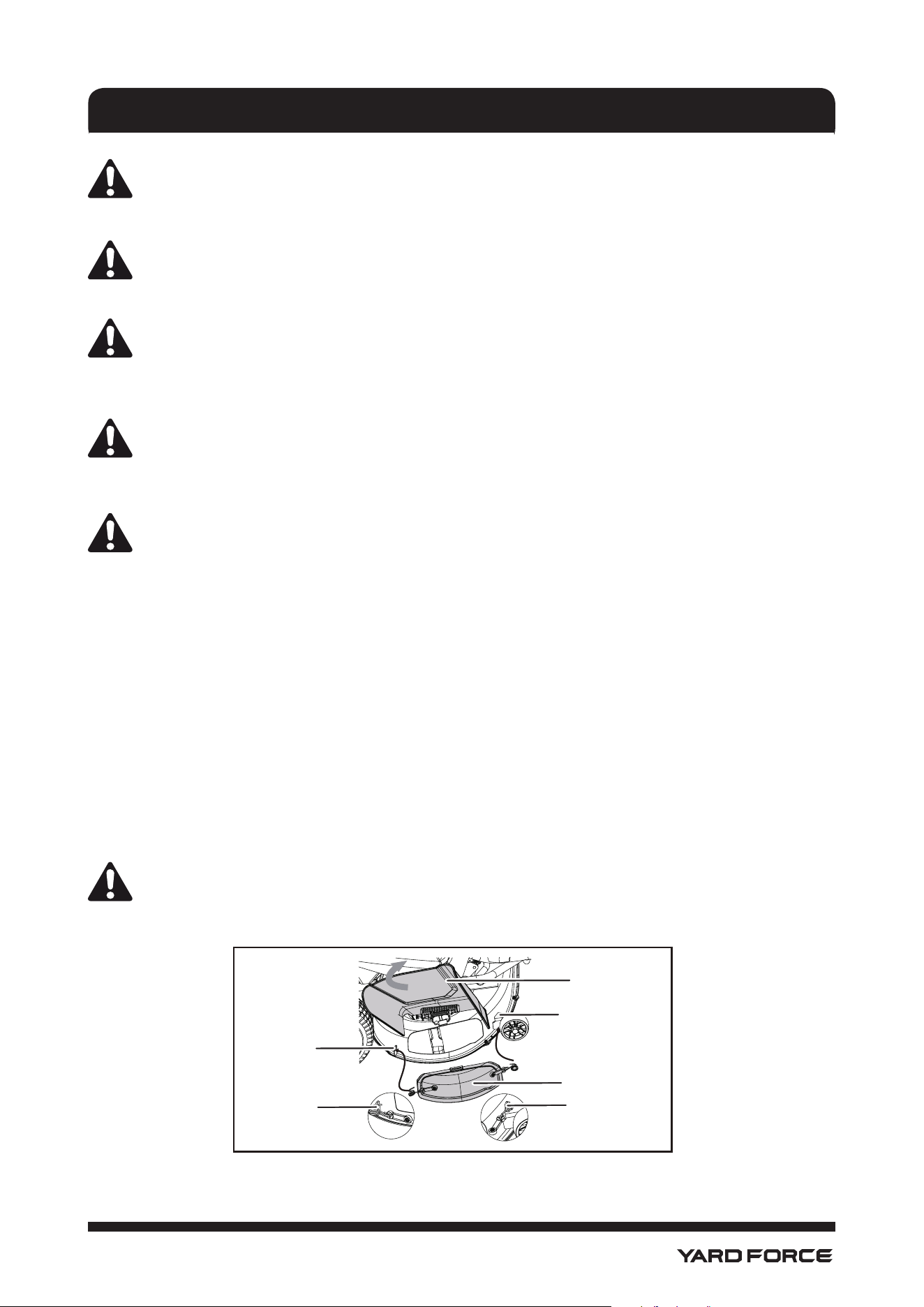
Fig. 10
TEST THE SAFETY INTERLOCK SYSTEM (See Fig. 10.)
This mower features a Safety Interlock System to protect the operator by shutting off the blades if the
operator leaves the seat with the blades running. Test the system to be sure it is working correctly.
To test:
• Make sure direction control switch is in neutral (N) position and blade engage knob is down.
• Install start key and turn to ON position.
• Raise blade engage knob to activate blades.
• Briey lift off the seat, but do not get off the mower.
• The blades should shut off within 5 seconds. If they don’t, verify you connected the safety interlock
cable as described on page 17. If the cable is connected but the system still doesn’t function, contact
Yard Force Customer Service at 1-866-902-9690 (US), or 1-833-818-4111 (CA). Do not operate the
mower until the safety interlock system has been repaired.
ASSEMBLY
21
1-866-902-9690
OPERATION
WARNING!
Do not allow familiarity with products to make you careless. Remember that a careless fraction of a
second is sufcient to inict serious injury.
WARNING!
Always wear eye protection with side shields marked to comply with ANSI Z87.1. Failure to do so
could result in objects being thrown into your eyes resulting in possible serious injury.
WARNING!
Always turn off mower, make sure blades have stopped moving, and remove the start key from the
mower when you are assembling parts, making adjustments, cleaning, or when not in use. This will
prevent accidental starting that could cause serious personal injury.
WARNING!
Always inspect mower for missing or damaged parts and blades for damage or uneven or excessive
wear prior to use. Use of the mower with damaged or missing parts can result in serious personal
injury.
NOTICE!
Before each use, inspect the entire product for damaged, missing, or loose parts such as screws,
nuts, bolts, caps, etc. Tighten securely all fasteners and caps and do not operate this product until
all missing or damaged parts are replaced. Please Yard Force Customer Service at 1-866-902-9690
(US), or 1-833-818-4111 (CA) or a qualied service center for assistance.
APPLICATIONS
You may use this product for the purpose listed below:
• Mowing your lawn
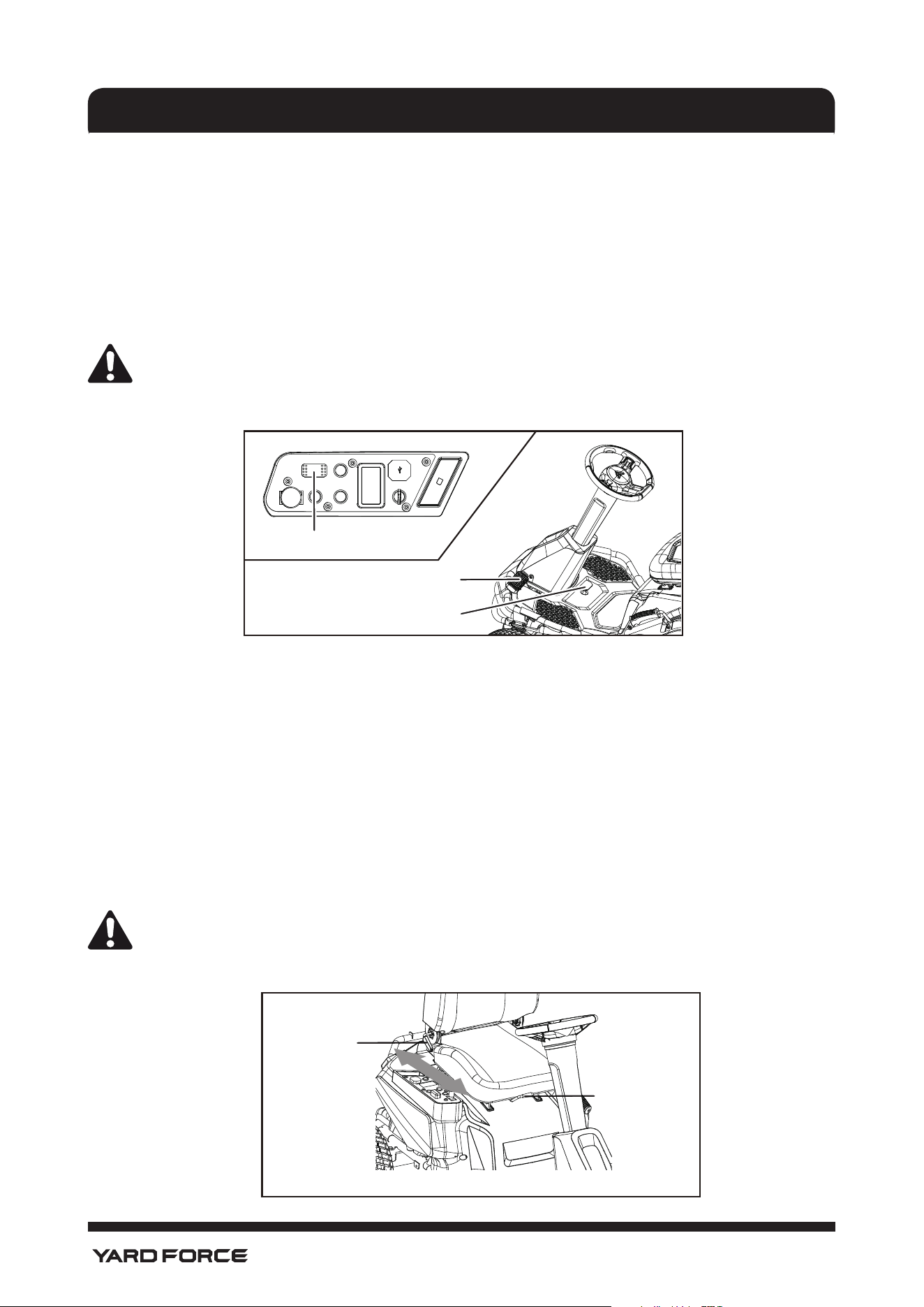
INSTALLING MULCH COVER (See Fig.11.)
The mower is congured for side discharge when shipped. If mulching is desired:
• Set parking pedal, turn off mower and remove key. Ensure the blades have stopped.
• Lift the side discharge chute.
• Place the mulch cover over the opening for side- discharge.
• Connect the mulch cover latches to the two side mounting points on the mower deck housing.
• Release the side discharge chute.
WARNING!
Make sure the side discharge chute fully closes when nished. Failure to do so could cause serious
personal injury.
Fig. 11
Side Discharge
Chute
Hole
Mulch Cover Set
Hole
Hole
Hole
22
1-866-902-9690
OPERATION
SETTING AND RELEASING THE PARKING BRAKE (See Fig.12.)
To set the parking brake:
• Place the direction control switch in the neutral (N) position.
• Fully depress and hold the brake pedal.
• Fully depress and hold the parking pedal.
• Release the brake pedal.
• Release the parking pedal.
To release the parking brake:
• Depress and release the brake pedal.
WARNING!
Never leave the mower unattended when the product on or running. Verify that the parking pedal is
set and the key has been removed. Failure to set the parking pedal could cause the mower to move,
and leaving the key could allow unauthorized use that could result in serious personal injury.
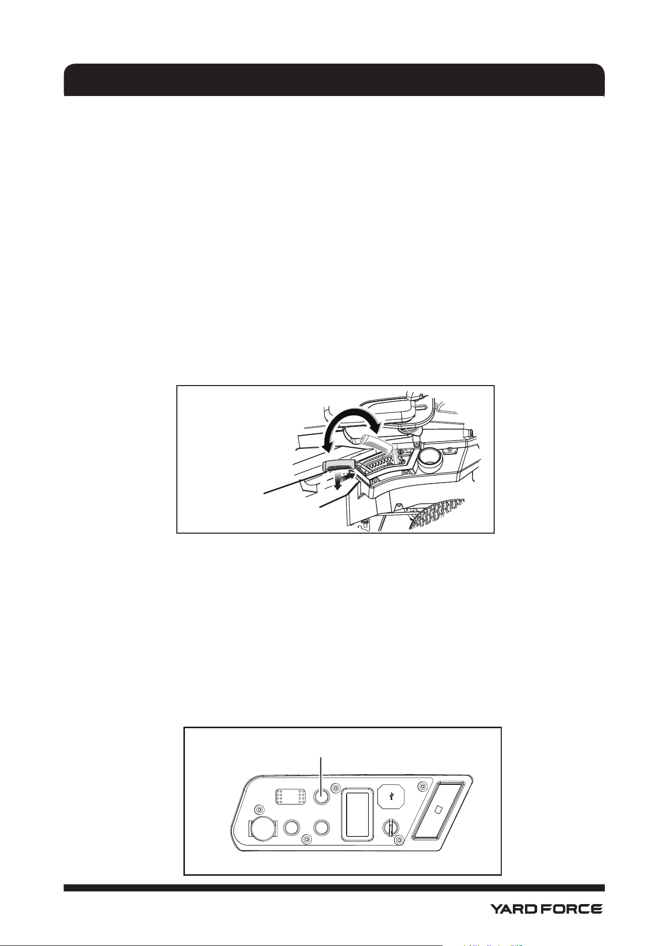
ADJUSTING THE SEAT (See Fig.13.)
Adjust the seat position to ensure you are able to make rm contact with the accelerator and brake pedals
before operating the mower.
To move the seat:
• Sit down on seat and lift the seat adjustment lever.
• While holding the lever, slide the seat to the desired position.
• Release the lever and make sure the seat is locked in position before operating the mower.
To adjust the seat back
• Sit down on the seat, keep your back in contact with the seat back.
• Lift the adjusting handle and move the back to a desired position.
• Release the handle to lock the position.
WARNING!
Be sure the seat is locked into place before operating the mower. A seat that is not secure can
cause the operator to shift and lose control of the mower and result in possible death or serious
personal injury.
Fig. 12
Parking Pedal
Brake Pedal
Direction Control Switch
Fig. 13
Seat Adjustment
Lever
Seat back adjusting
handle
23
1-866-902-9690
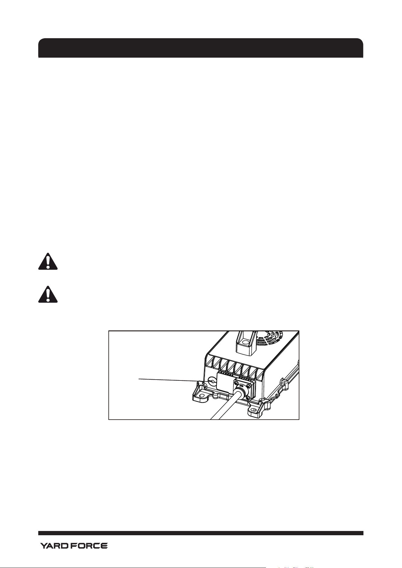
SETTING THE CUTTING DECK HEIGHT (See Fig.14.)
It is recommended the batteries are charged minimum 4 hours before rst use regardless of battery level
indicator reading. Mower batteries must be fully charged before rst use. To verify mower batteries are fully
charged, check the battery level indicator.
NOTE: To prevent scalping the lawn when encountering high spots, the cutting deck wheels should be
positioned approximately 1/2 in. off the ground when the mower is at the desired cutting height. When
shipped, the cutting deck wheels are set to the 1.5 in. position. Depending on your desired cutting height,
you may need to change the position of the cutting deck wheels. To do so, refer to Adjusting Cutting Deck
Wheels in the Maintenance section of this manual.
To adjust the cutting deck height:
• Stop the mower and disengage blades.
• Turn key to OFF position and set the parking pedal.
• To raise the cutting deck, grasp the deck height adjustment lever, push left to disengage from slot, move
toward the back of the mower, then push right into slot to secure.
• To lower the cutting deck, grasp the deck height adjustment lever, push left to disengage from slot,
move toward the front of the mower, then push right into slot to secure.
Hold the deck height adjustment lever rmly when setting the deck height and only release when it is secure
in the desired slot. Quickly letting go of the lever may create a pinching or pulling hazard to the operator’s
hand.
SETTING THE CRUISE CONTROL (See Fig.15.)
Cruise control allows the mower to remain at a constant speed without the operator having to maintain
pressure on the accelerator pedal. It should only be used in the forward position on relatively smooth,
straight surfaces, and should never be used on slopes or rough terrain.
To set the cruise control:
• While driving the mower forward, press the accelerator pedal until the desired rate of speed is achieved.
• Press the cruise control button. The light around the button will illuminate to show cruise control is
active.
• Release pressure on the accelerator pedal. Mower speed should remain constant.
• To release cruise control: tap on the accelerator pedal, depress the brake pedal, or press the cruise
control button again. The light around the cruise control button will go out to indicate cruise control is
no longer active.
OPERATION
Fig. 14
Deck Height
Adjustment Lever
Fig. 15
Cruise Control Button (CCS)
24
1-866-902-9690
CHARGING THE MOWER (See Fig.16.)
It is recommended the batteries are charged minimum 4 hours before rst use regardless of battery level
indicator reading. Mower batteries must be fully charged before rst use. To verify mower batteries are fully
charged, check the battery level indicator.
For best results:
• Do not charge in an area of extreme heat or cold.
• Never charge a frozen battery.
• Mount or place the charger in an area with adequate ventilation, ideally with the charger in a horizontal
position with the cooling ns facing up.
To charge:
• Make sure both the charger and mower connections are clean and free of dirt or debris.
• Insert charger plug into charging port on mower, making sure it is properly connected.
• Connect charger to power supply using normal household current of 120 V, AC only, 60 Hz. The
batteries should automatically begin to charge.
NOTE: The charger is equipped with a plug featuring a grounding pin and must be plugged into a
matching standard three-prong outlet that has been properly installed and grounded in accordance with
all local codes and ordinances. Do not use a two-prong outlet, adaptors, or modify the plug provided. If
it will not t the outlet, have the proper outlet installed by a qualied electrician.
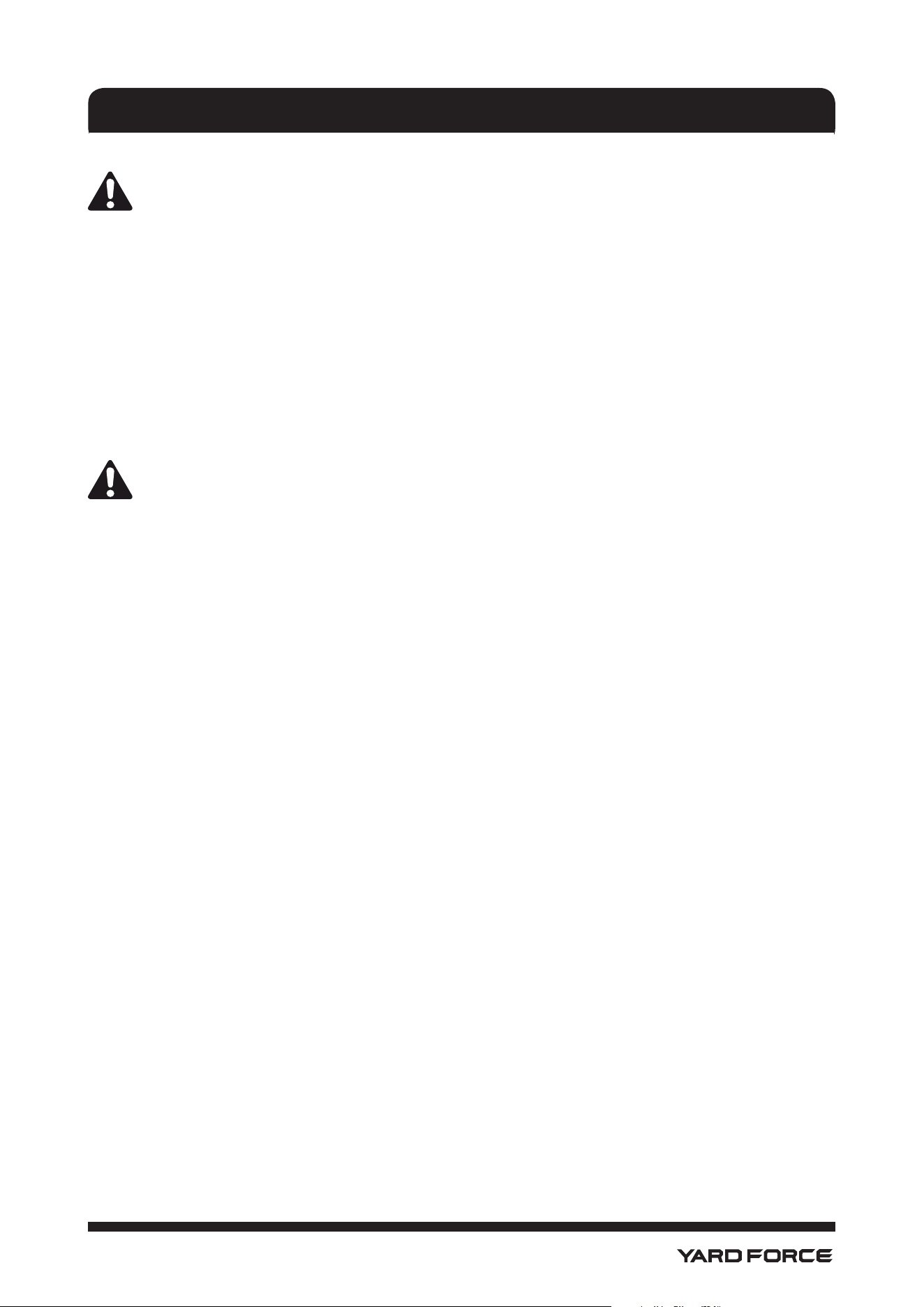
• When powered, the LED indicator on the charger will illuminate to indicate the charger’s status. Refer to
the chart below Fig. 16 to determine the meaning of the LED’s display.
• When you are ready to mow, disconnect the charger from the power supply, then disconnect the
charger from the mower.
NOTICE!
Always turn power switch to OFF position and remove key when charging mower and when mower
is not in use.
NOTICE!
Always connect the mower to the charger when the unit is not in use. If it is not possible to leave the
mower charger connected, make sure to charge the batteries fully at least once a month.
OPERATION
Fig. 16
LED Indicator
on Charger
25
1-866-902-9690
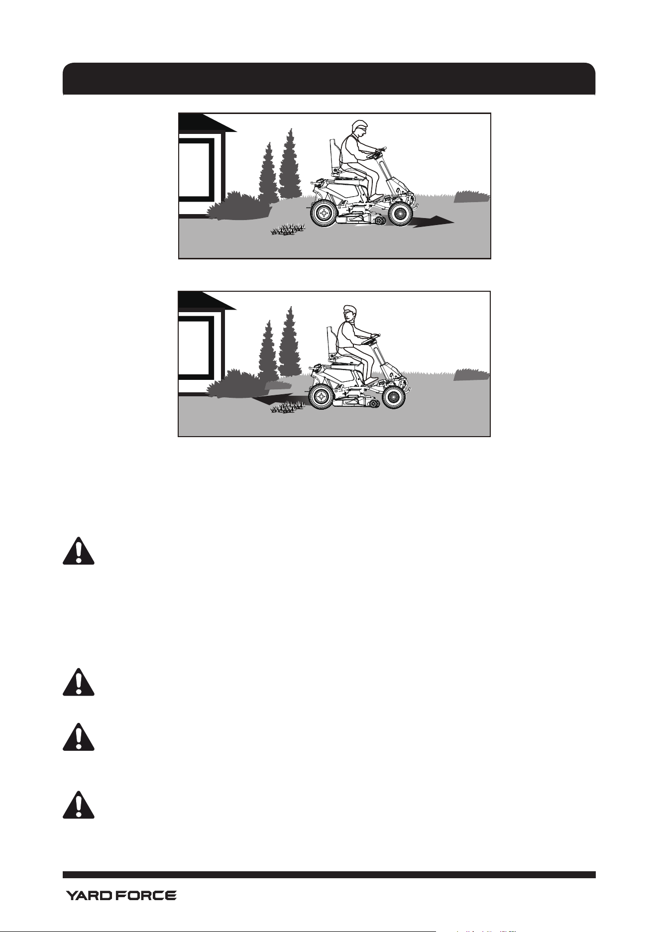
OPERATING THE MOWER (See Fig.17&18.)
WARNING!
Clear the area of bystanders before operating the mower. If anyone enters the mowing area, stop
immediately and do not return to mowing until the bystanders leave the area.
Before starting the mower:
• Ensure work area is clear of children, bystanders, and pets.
• Clear the work area of objects that may be thrown by the mower blades.
• Check brake operation.
• Check tire pressure.
• Check for loose fasteners.
• Check to make sure all guards are in place and working properly.
• Clean debris from mower.
• Test safety interlock system.
• Adjust seat to desired position.
• Verify battery charge level.
NOTICE!
When the level of battery charge reaches the red zone on the battery charge indicator, the blades will
automatically shut off. Return immediately to recharge. Continuing to mow when the battery charge
level is in the red zone can cause the mower to become stranded away from the charging area.
NOTE: If the mower becomes stranded away from the charger, it will be necessary to place the direction
control switch in neutral (N) and push the mower back to the charging location.
OPERATION
26
1-866-902-9690
Mowing:
• Raise the mower deck to its highest position.
• Insert start key and turn to ON position.
• To release the parking brake: depress and release the brake pedal.
• Place direction control switch in forward (F) position and drive to desired mowing location.
WARNING!
Be certain you have correctly set your intended direction of travel with the direction control switch
before pressing the accelerator pedal. Failure to do so could result in you driving the mower in an
unintended direction, which could cause loss of control or an accident resulting in death, serious
personal injury, or property damage.
• Stop the mower, turn key to OFF position, and set the parking brake.
• Lower cutting deck to desired position.
• Turn start key to ON position and release parking brake.
• Raise blade engage knob to activate blades and press accelerator pedal to mow as desired.
WARNING!
Use caution when crossing over gravel paths or drive- ways. Before crossing, disengage the blades
and raise the cutting deck to the highest position to minimize the possibility of ricochet. Drive slowly
to avoid loss of traction and control.
NOTICE!
Do not attempt to change the direction of operation while the mower is in motion. Always come to a
complete stop before changing the mower direction.
Reverse mode operation:
NOTICE!
The mower will emit a constant beeping sound when operated in reverse with either the blade off or
in reverse mode operation.
• Depress the brake pedal and bring the mower to a complete stop.
• Push blade engage knob down to turn blades off.
OPERATION
Fig. 18
Reverse Mode Operation
Fig. 17
Forward Mowing
27
1-866-902-9690
• Place direction control switch in reverse (R) position.
• Press the reverse mode button.
• Raise the blade engage knob, slowly press accelerator pedal, and reverse mow as needed.
WARNING!
Do not mow in reverse unless absolutely necessary. Always look down and behind before and
while backing to make sure no children, bystanders, or pets enter the mowing area. Be aware that
the reverse mode operation is activated when the reverse mode button is illuminated in red and a
constant beeping sound is emitted. Remember that a careless fraction of a second is sufcient to
inict death or serious injury.
WARNING!
Be especially careful before and when backing with the bagger kit installed, as it may limit visibility.
Always look closely behind and down for small children, bystanders, and pets and move the mower
slowly to prevent back over accidents that can cause death or serious personal injury.
When mowing is complete:
• Stop mower on a at, level surface. Do not stop the mower on a slope.
• Push the blade engage knob down to turn blades off.
• Place the direction control switch in the neutral (N).
• Set the parking brake.
• Turn the start key OFF.
NOTE: Reverse mode operation resets each time the power switch is turned to the OFF position.
WARNING!
If the mower emits a beeping noise after you leave the seat, verify that the parking brake is set and
the key has been removed. Failure to set the parking brake could cause the mower to move, and
leaving the key could allow unauthorized use that could result in serious personal injury.
MOWING TIPS (See Fig.19.)
• Keep mower blades sharp.
• Make sure the lawn is clear of stones, sticks, wires, toys, tree nuts, tree branches, and other objects
that could damage the lawn mower blades or motor. Do not mow over property stakes or other metal
posts. Such objects could damage the blade or be accidentally thrown by the mower in any direction
and cause serious personal injury to the operator and others.
• For a healthy lawn, always cut off one-third or less of the total length of the grass.
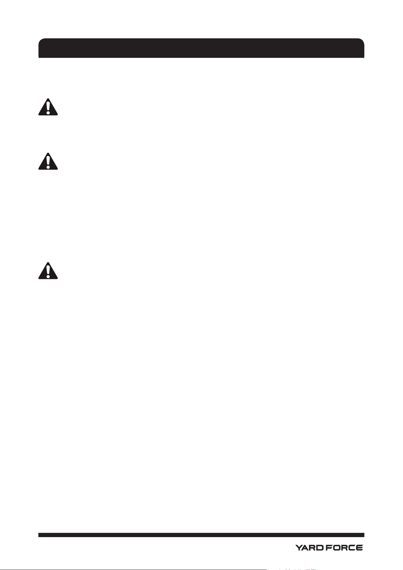
• When mowing large areas, start by turning to the right so that clippings will discharge away from shrubs,
fences, driveways, etc. After one or two rounds, mow in the opposite direction, making left hand turns
until nished.
• Mow so that discharged clippings exit in the direction of the lawn area that has already been cut.
• When cutting heavy grass, reduce speed to allow for more effective cutting and a proper discharge of
the clippings.
• Do not cut wet grass. It will stick to the underside of the deck and prevent proper bagging or mulching
of grass clippings.
• New or thick grass may require a narrower cut or a higher cutting height.
• Keep the mower deck and side discharge chute clean. Remove grass clippings, leaves, dirt, and any
other accumulated debris before and after each use. Do not spray with a garden hose to clean.
NOTE: Always stop mower, allow blades to completely stop, and remove the start key before cleaning
underneath the mower.
OPERATION
28
1-866-902-9690
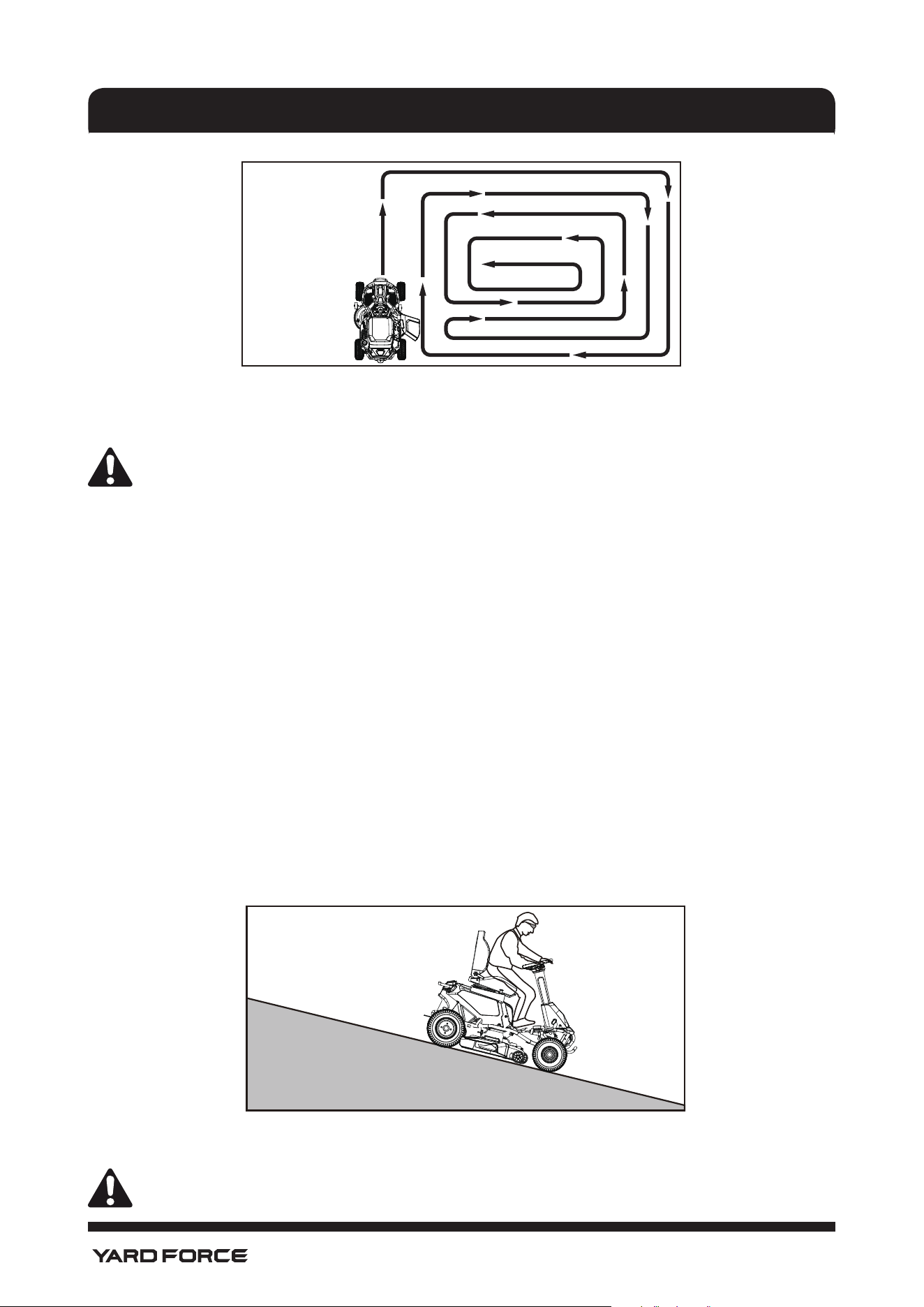
SLOPE OPERATION (See Fig.20.)
WARNING!
Slopes are a major factor related to tip-over and roll-over accidents that can result in severe injury or
death. Operation on slopes requires extra caution. If you feel uneasy on a slope, do not mow it. For
your safety, do not attempt to mow steep slopes greater than 15 degrees. Make a copy or cut out
the slope guide image at the back of this manual and use to determine if your slope is too steep for
safe operation.
• Mow up and down, not across the face of slopes.
• Do not mow on wet grass. Wet grass can cause the tires to lose traction or slip on slopes, even though
the brakes are functioning properly.
• Watch for holes, ruts, rocks, hidden objects, or bumps which can cause you to slip or trip. Tall grass
can hide obstacles. Remove all objects such as rocks, tree limbs, etc., which could be tripped over or
thrown by the blade.
• Do not mow near drop-offs, ditches, or embankments.
• Drive slowly and do not make sudden changes in speed or direction.
• Avoid stopping on slope if at all possible. If stopping is unavoidable, make sure to engage parking
pedal. When restarting, use lowest possible speed. If turning is necessary, exercise extreme caution
when changing direction and always turn downhill.
• Never attempt to stabilize the mower on a slope by placing your foot on the ground during operation.
• If using the optional bagger kit, use extreme caution and operate the mower slowly when operating on
slopes, as the bagging kit can change the stability of the mower.
• Always use the brakes when travelling down the slope. Do not attempt to let the mower coast downhill
in neutral.
• If at any point the tires lose traction while operating on a slope, disengage the blades and proceed
slowly and carefully straight down the slope.
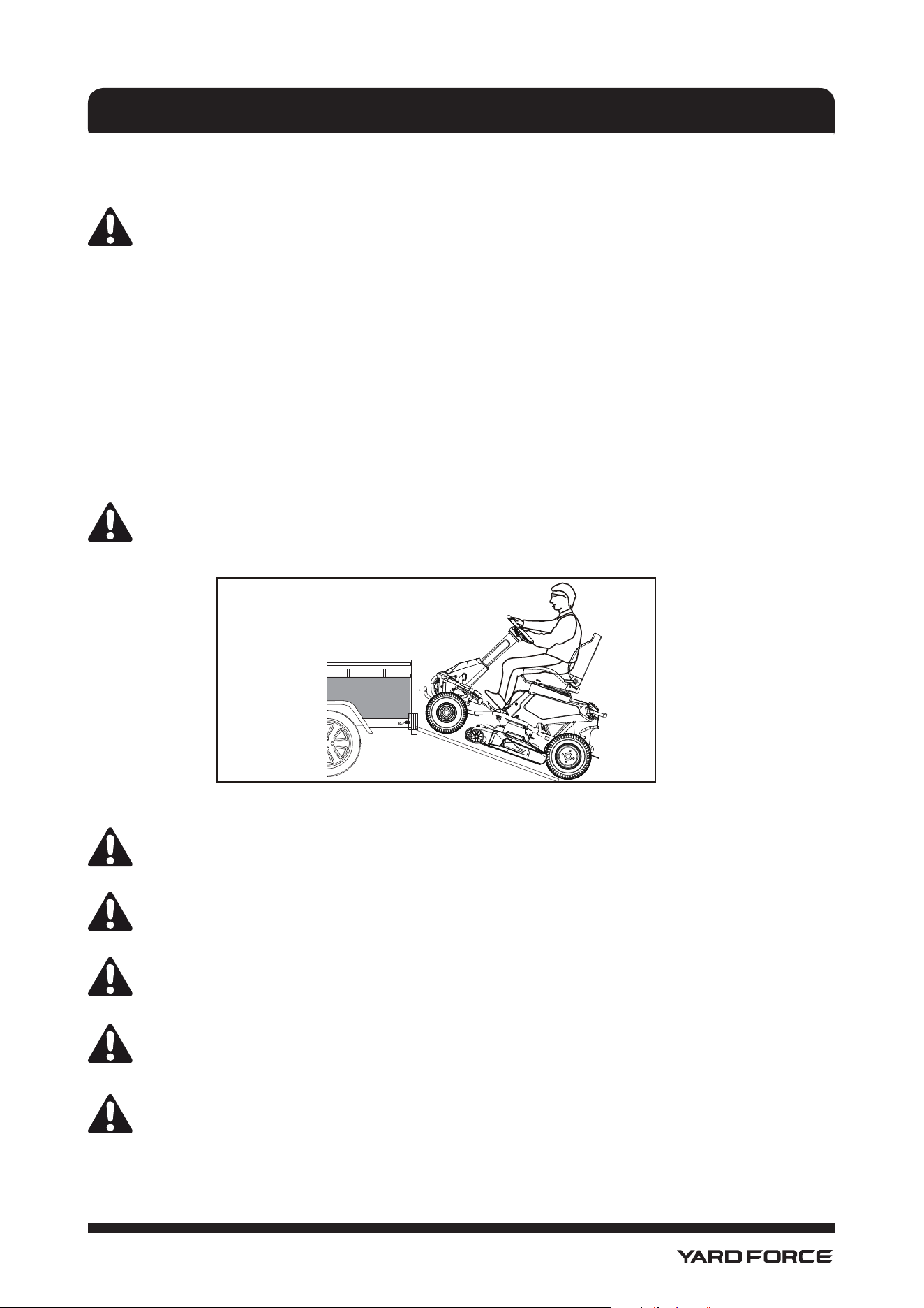
TRANSPORTING THE MOWER (See Fig.21.)
WARNING!
Use care when driving the mower off of or onto a trailer or truck and press the brake pedal as
OPERATION
Fig. 19
Fig. 20
29
1-866-902-9690
needed to control the speed. The mower will freely roll if it is moved on an inclined surface without
pressing the brake pedal or setting the parking brake. Failure to follow these instructions can result
in loss of control and result in death, serious personal injury, or property damage.
WARNING!
Use care when loading or unloading the mower onto a trailer. Ensure the cutting deck is raised to the
highest position so that it is not caught on the ramp. The wheels on the mower can go off the ramp
or trailer, causing the mower to pivot or tip over, and result in a crush hazard that can cause death or
serious personal injury.
• Park the mower on a level surface.
• Raise the cutting deck to the highest position.
• Position and secure ramp to the trailer according to manufacturer’s instructions.
NOTE: We recommend you use one full width loading ramp that is at least 1 ft. wider than the mower to
minimize the risk of the mower’s wheels going off the side of the ramp.
• Slowly drive the mower onto the ramp and into the trailer.
• Lower mower deck completely.
• Set the parking brake.
• Turn off mower and remove key.
• Secure the mower as needed using straps or cables to prevent movement during transport.
WARNING!
To avoid accidental starting or movement that could result in serious personal injury, always remove
the start key and set the parking brake when transporting the mower.
MAINTENANCE AND STOARGE
WARNING!
Before performing any maintenance, stop the mower, wait for the blades to come to a complete
stop, and remove the start key to avoid accidental starting and possible serious personal injury.
WARNING!
Always wear eye protection with side shields marked to comply with ANSI Z87.1. Failure to do so
could result in objects being thrown into your eyes resulting in possible serious injury.
WARNING!
When servicing, use only authorized replacement parts. Use of any other parts can create a hazard
or cause product damage.
WARNING!
Strictly adhere to all torque wrench tightening specications. Failure to do so could cause serious
personal injury.
NOTICE
!
Periodically inspect the entire product for damaged, missing, or loose parts such as screws, nuts,
bolts, caps, etc. Tighten securely all fasteners and caps and do not operate this product until all
missing or damaged parts are replaced. Please contact Yard Force Customer Service at 1-866-
902-9690 (US), or 1-833-818-4111 (CA) or a qualied service center for assistance.
MAINTENANCE AND STOARGE
Fig. 21
30
1-866-902-9690
GENERAL MAINTENANCE
Avoid using solvents when cleaning plastic parts. Most plastics are susceptible to damage from various
types of commercial solvents and may be damaged by their use. Use clean cloths to remove dirt, dust, oil,
grease, etc.
Remove any build-up of grass and leaves on or around the motor cover. Wipe the mower clean with a dry
cloth occasionally. Do not use water.
WARNING!
Do not at any time let brake uids, gasoline, petroleum- based products, penetrating oils, etc., come
in contact with plastic parts. Chemicals can damage, weaken, or destroy plastic which can result in
serious personal injury.
CLEANING THE MACHINE
Remove any build-up of grass and leaves on or around the mower housing. Wear eye protection and
use compressed air after each use to clean the mower housing or the top side of the mower deck. The
underside of mower deck should also be cleaned using wash port after each use, as grass clippings,
leaves, dirt, and other debris will accumulate, especially when grass is wet or has high moisture content.
This accumulation is undesirable, as it will harden, restricting blade and air movement, probably resulting in
a poorer quality of cut and even promoting rust and corrosion.
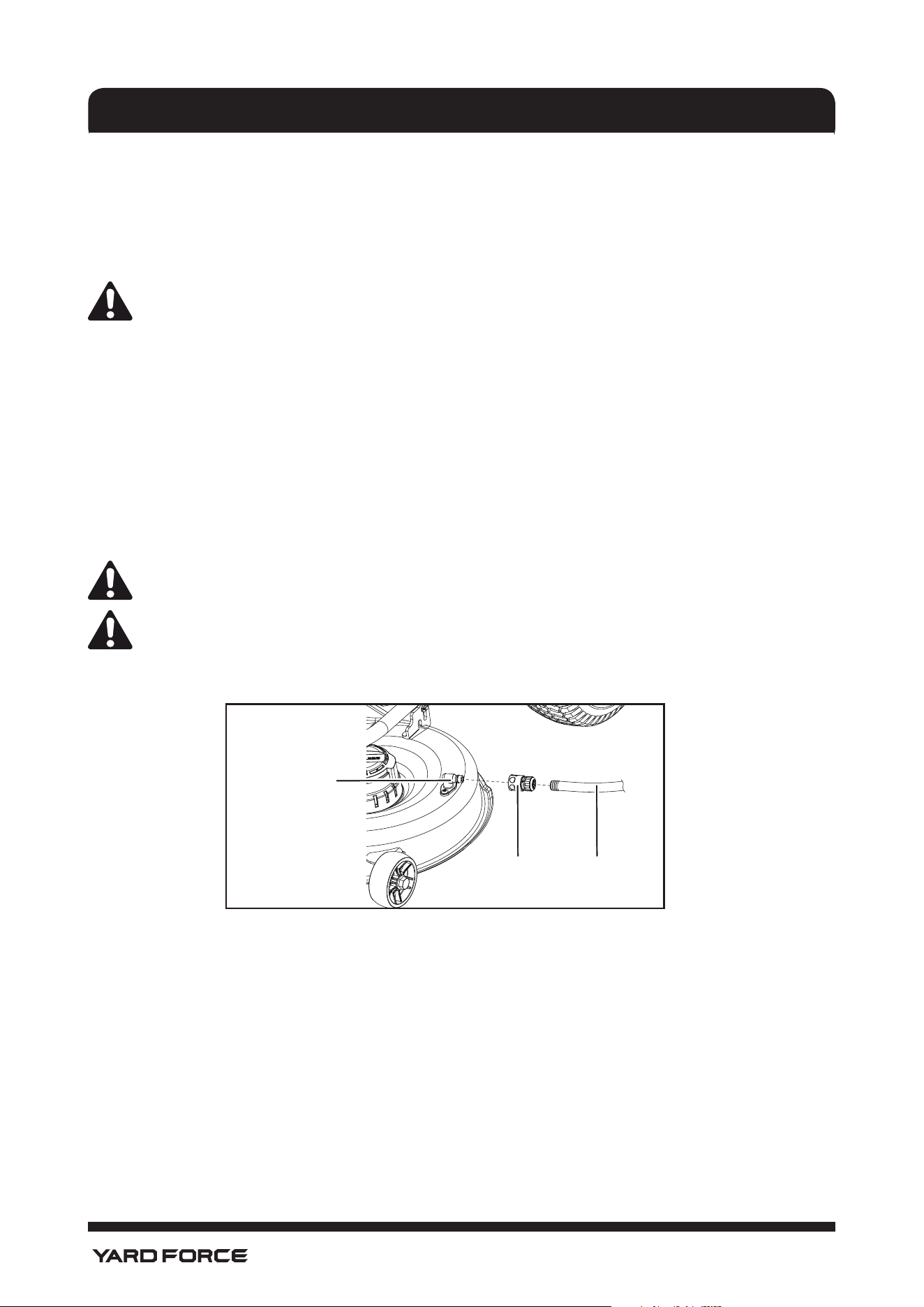
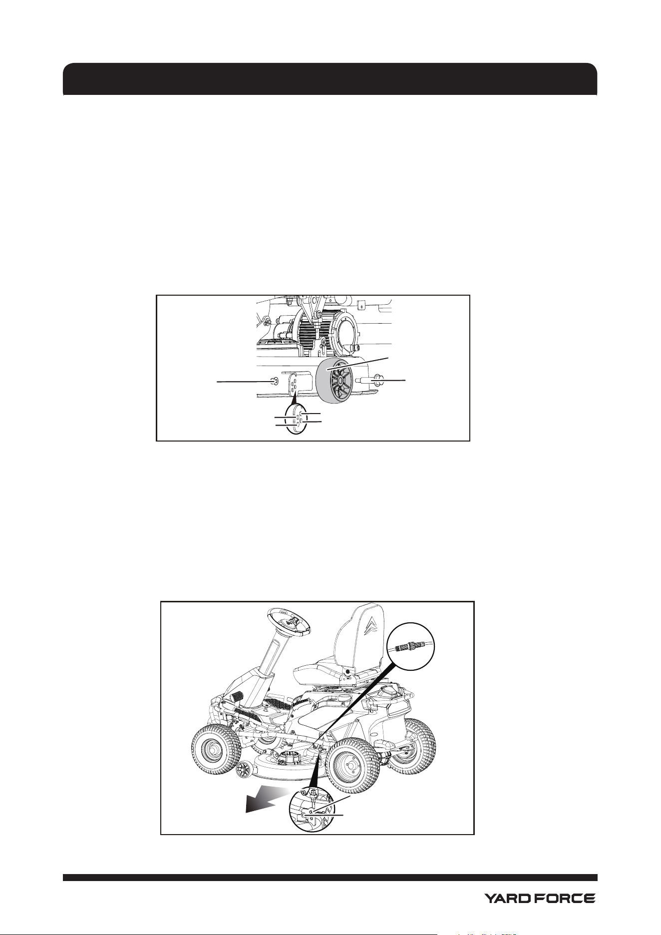
USING WASH PORT TO CLEAN MOWER DECK (See Fig.22.)
NOTICE
!
Follow this procedure after EACH USE to prevent buildup and remove corrosive lawn chemicals.
NOTICE
!
You can wash the machine with a mild detergent and water. Do not pressure wash the machine.
Avoid excessive use of water, especially near the control panel, under the seat, around the motors
and all electric components and bearings.
• On a at, level surface set the parking pedal to the parking position. Refer to section “SETTING THE
PARKING PEDAL” in this manual.
• Stop the motor and allow the blades to come to a complete stop. Adjust the mower deck height to the
lowest position. refer to section "SETTING THE CUTTING DECK HEIGHT" in this manual.
• Attach the supplied wash-port quick-coupler to garden hose.
• Attach garden hose with quick-coupler to wash port on the mower deck. The wash port is on the left
side of the mower deck.
• Turn on the water.
• Turn on the power switch and pull the blade engage knob to start the mower cutting blades.
• Flush water under the deck for approximately one minute.
• Disengage the mower blades by pushing the blade engage knob downward.
• Turn off the water and remove garden hose and quick-coupler from wash port.
• Remove quick-coupler from garden hose and store for future use.
• Turn off the mower completely.
MAINTENANCE AND STOARGE
Fig. 22
Wash Port
Wash-port
Quick Coupler
Garden Hose
31
1-866-902-9690
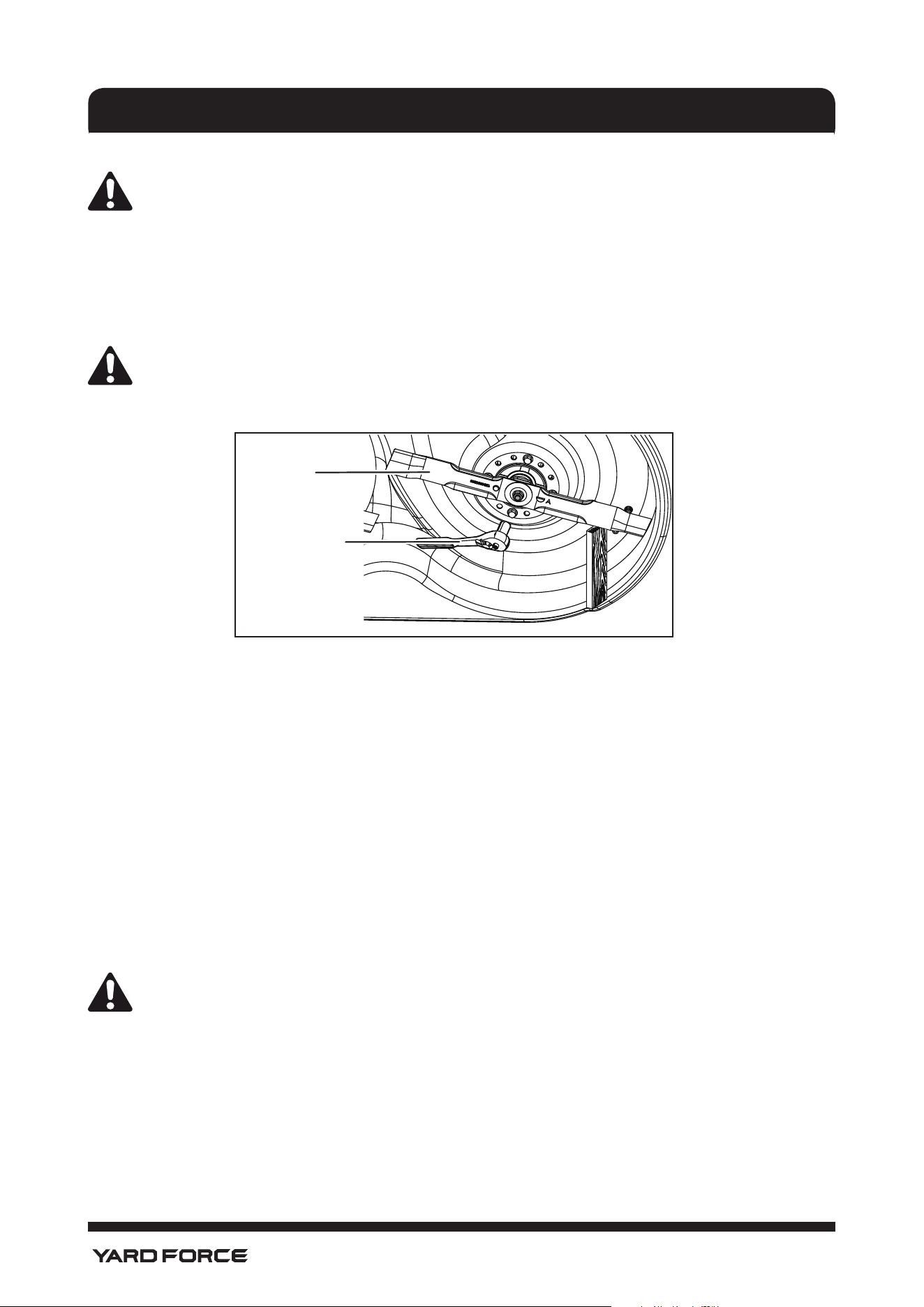
ADJUSTING CUTTING DECK WHEELS (See Fig. 23)
The cutting deck wheels should be positioned approximately 1/2 in. off the ground when the mower is at the
desired cutting height. This will minimize the chance of scalping the lawn in most situations. When shipped,
the wheels are positioned in Position A.
To adjust the cutting deck wheels:
• Park the mower on a level surface and set the parking brake.
• Turn off the mower and remove the start key. Allow blades to come to a complete stop.
• Raise the cutting deck to the desired height setting.
• Remove nut and bolt holding cutting deck wheel in place.
• Move wheel to desired position. Available hole positions are 1.5 in. (A), 1.75 in. (B), 2 in. (C) and 2.25 in.
(D).
• Replace bolt and nut; tighten securely. Torque nut to 4-6 ft. lbs.
• Repeat with remaining cutting deck wheel, making sure both wheels are installed in the same position.
REMOVING THE CUTTING DECK (See Fig. 24.)
If desired, the cutting deck can be removed from the mower to make accessing the blades easier when
changing.
• Make sure direction control switch is in neutral (N) position and blade engage knob is down.
• Turn off the mower, remove the start key, and set the parking brake.
• Disconnect the cables that connect the cutting deck to the mower.
• Lower the cutting deck to its lowest position.
• Remove the 4 hitch pins and washers that secure the cutting deck in place.
• Slide the deck out from under the mower.
• Reverse the process to reattach the cutting deck to the mower.
MAINTENANCE AND STOARGE
Fig. 23
Nut
Bolt
A
C
D
B
Wheel
Cutting Deck
Hitch Pin
Washer
Cable
Fig. 24
32
1-866-902-9690
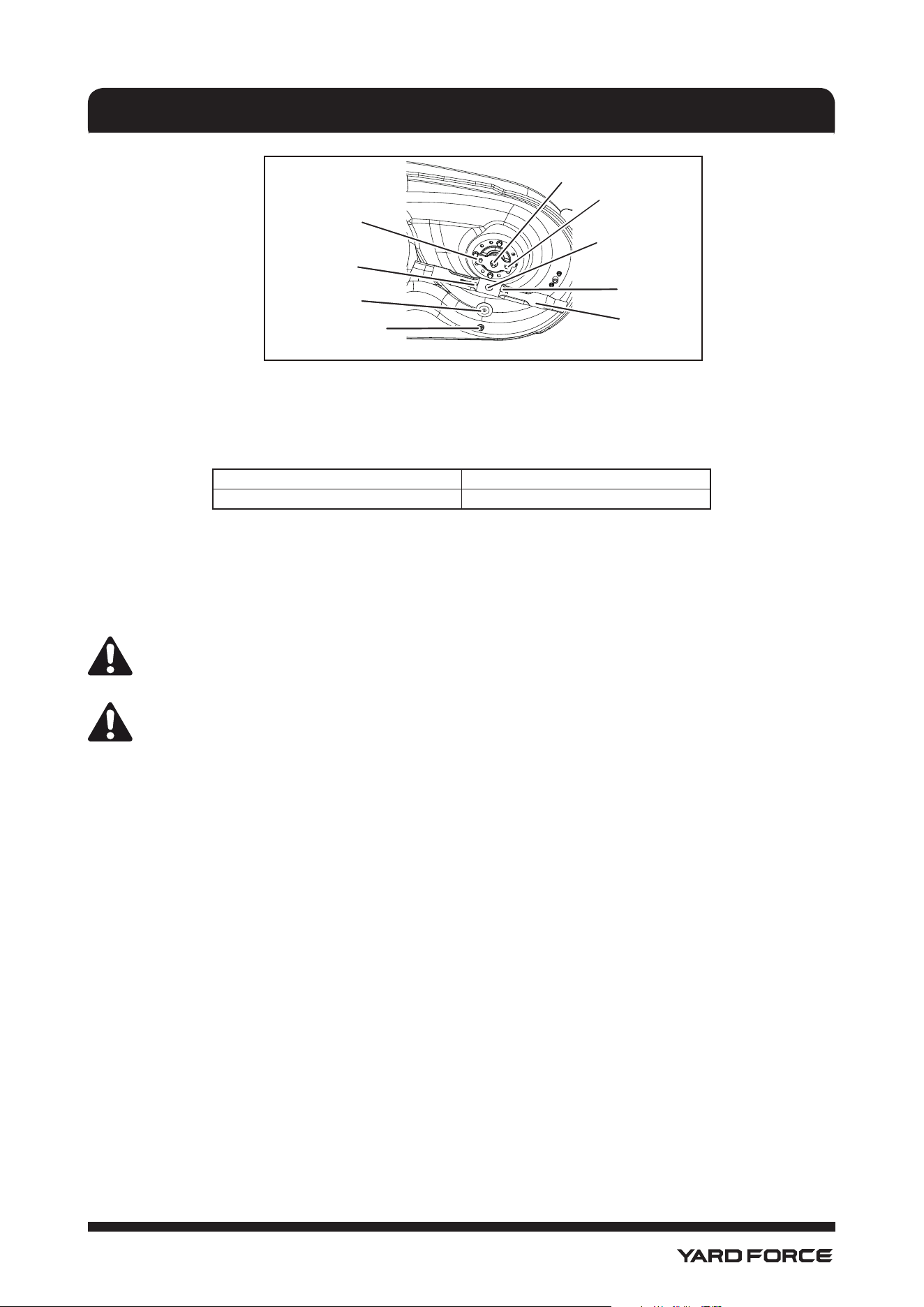
REPLACING CUTTING BLADES (See Fig. 25&26)
CAUTION!
Only use replacement blades and blade bolts authorized by the manufacturer of your riding mower.
Use of blades and blade bolts not authorized is hazardous and may damage your riding mower.
• Make sure direction control switch is in neutral (N) position and blade engage knob is down.
• Turn off the mower, remove the start key, and set the parking pedal.
• Raise the height of the cutting deck to its highest position to allow access to blades.
NOTE: If necessary, raise the mower by placing on a lift or using a jack with tire chocks and jack stands, or
remove the cutting deck as described in the previous section to gain access to the blades.
WARNING!
If raising the mower to access the blades, make sure the mower is properly secured and the parking
pedal is set before proceeding. Failure to properly secure the mower could cause it to fall, resulting
in death or possible serious personal injury.
• Wedge a block of wood between the blade and mower deck to prevent the blade from turning.
• Loosen the blade nut by turning it counterclockwise (as viewed from bottom of mower) using a 14 mm
wrench or socket (not provided).
• Remove the blade nut, spacer, blade insulator, and blade.
• Place the new blade on the shaft against the corresponding blade posts. Ensure blade is properly
seated with shaft going through center blade hole and the two blade posts inserted into their respective
holes on the blade. Make sure it is installed with the curved ends pointing up toward the mower deck
and not down toward the ground. When seated properly, the blade should be at against the blade
posts.
• Replace the blade insulator and spacer, making sure the at sides on each piece align and the straight
sides of the opening on the spacer are aligned with the straight sides of the blade shaft.
NOTE: Make certain all parts are replaced in the exact order in which they were removed.
• Thread the blade nut on the shaft and nger tighten.
• Torque the blade nut down clockwise using a torque wrench (not provided) to ensure the bolt is properly
tightened. The recommended torque for the blade nut is 600-650 in. lbs.
• Repeat with second blade, if needed.
WARNING!
Ensure blade is properly seated and the blade nut is tightened to the torque
specications above. Failure to properly attach the blade could cause it to come loose and result in
possible serious personal injury.
MAINTENANCE AND STOARGE
Fig. 25
Wrench
Blade
33
1-866-902-9690
TIRE MAINTENANCE
This mower is equipped with tubeless tires of the size and type listed below:
Front Tire Size Rear Tire Size
15" x 6" x 6" 16" x 6.5" x 8"
Tire Air Pressure
Check the air pressure in all tires before use. Improper air pressure will affect handling, steering response,
traction, tire life, level cutting, and operator comfort. Be sure tires are inated to the pressure shown below.
NOTE: Tire pressure should only be measured or adjusted when tires are cold.
Recommended Pressure: 20 PSI (137 kPa)
WARNING!
Check the tire pressure carefully while inating. Too much air in the tire could cause the tire to burst,
causing serious personal injury.
WARNING!
Maintaining correct air pressure in the tires is very important. Too little pressure could allow the
tire to rotate off the wheel rim. Too much pressure could cause the tire to burst. Failure to maintain
correct air pressure in the tires could cause problems with mower operation and stability, causing
serious personal injury.
TIRE REPAIR
If a leak or at tire occurs due to a puncture, the tire may be repaired using a plug-type patch. If the damage
is from a cut, or if the puncture cannot be repaired using a plug, the tire should be replaced.
REPLACING TIRES
When tires are worn, the traction of the mower will be decreased, which increases the chance of having
an accident. Tires should be replaced when the depth on the tread is 5/32 in. (4 mm) or less, or any time
there is damage to the tire. Always use identical replacement tires. Using improper tires on the mower could
cause loss of control, which could cause serious personal injury.
Have tires replaced by an authorized service center or a qualied tire repair station.
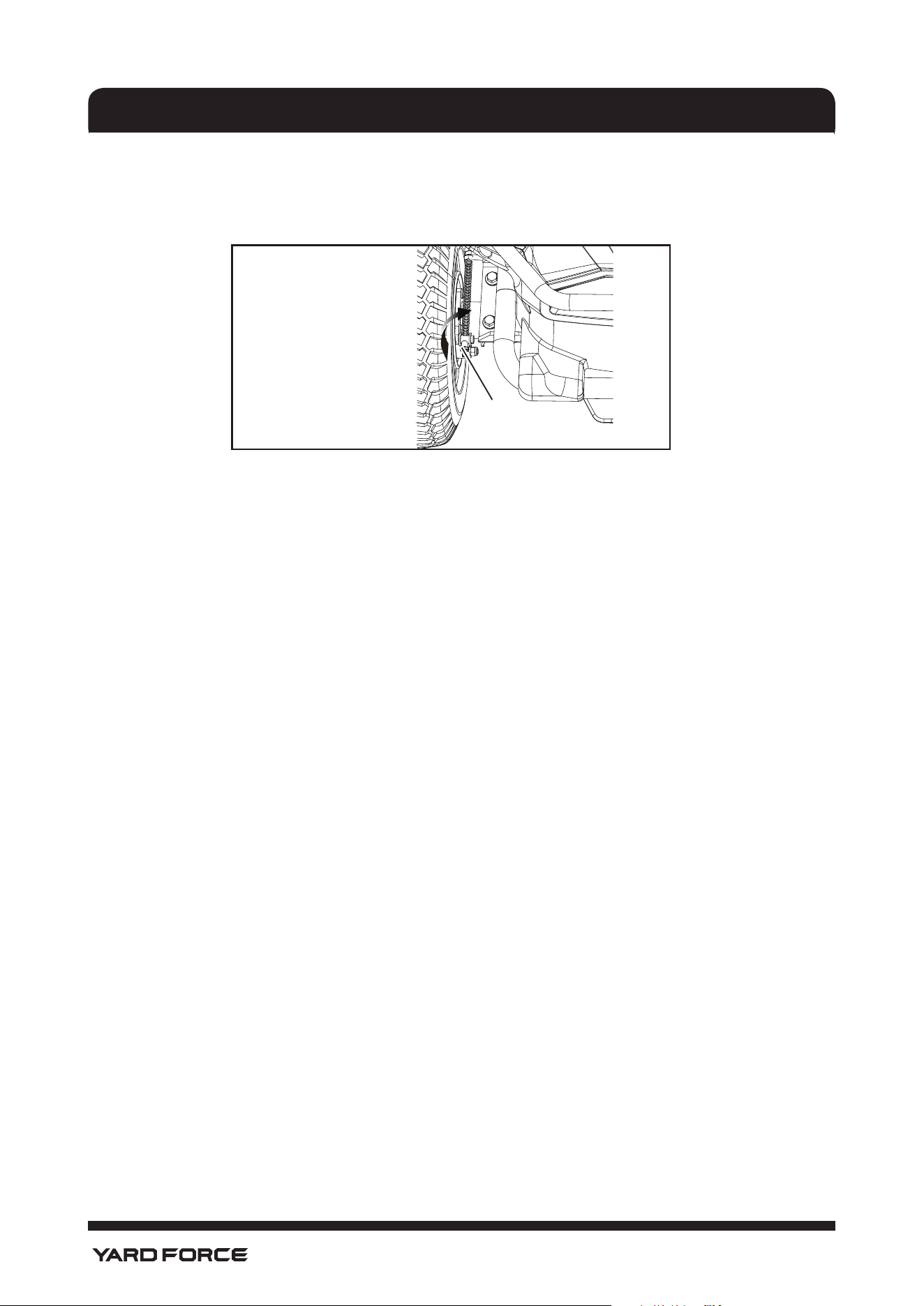
ADJUSTING THE BRAKES (See Fig. 27)
Being able to stop the mower properly is critical to mowing safety. If you’ve noticed your mower traveling
farther before stopping when you depress the brake pedal, the brakes may need adjusting.
To test:
• Park the mower on a level surface and set the parking brake.
• Place the direction control switch in neutral (N).
• Stand behind the mower and try to push it forward. If the rear tires turn, the brakes need to be
tightened.
To tighten:
• Locate the brake adjustment nuts on the interior side of each of the rear wheels.
MAINTENANCE AND STOARGE
Fig. 26
Blade
Circle Post
Shaft
Blade
Circle Hole
Center
Blade Hole
Blade Half
Circle Post
Blade Half
Circle Hole
Blade
Spacer
Blade Nut
34
1-866-902-9690
• Turn each adjustment nut 1/4 turn clockwise, then try again to push the mower.
• Continue rotating each nut 1/4 turn and testing until the mower can no longer be moved by pushing.
After nal adjustment, test the brakes by driving the mower at normal speed on at ground to be sure the
mower stops quickly when the brake pedal is depressed.
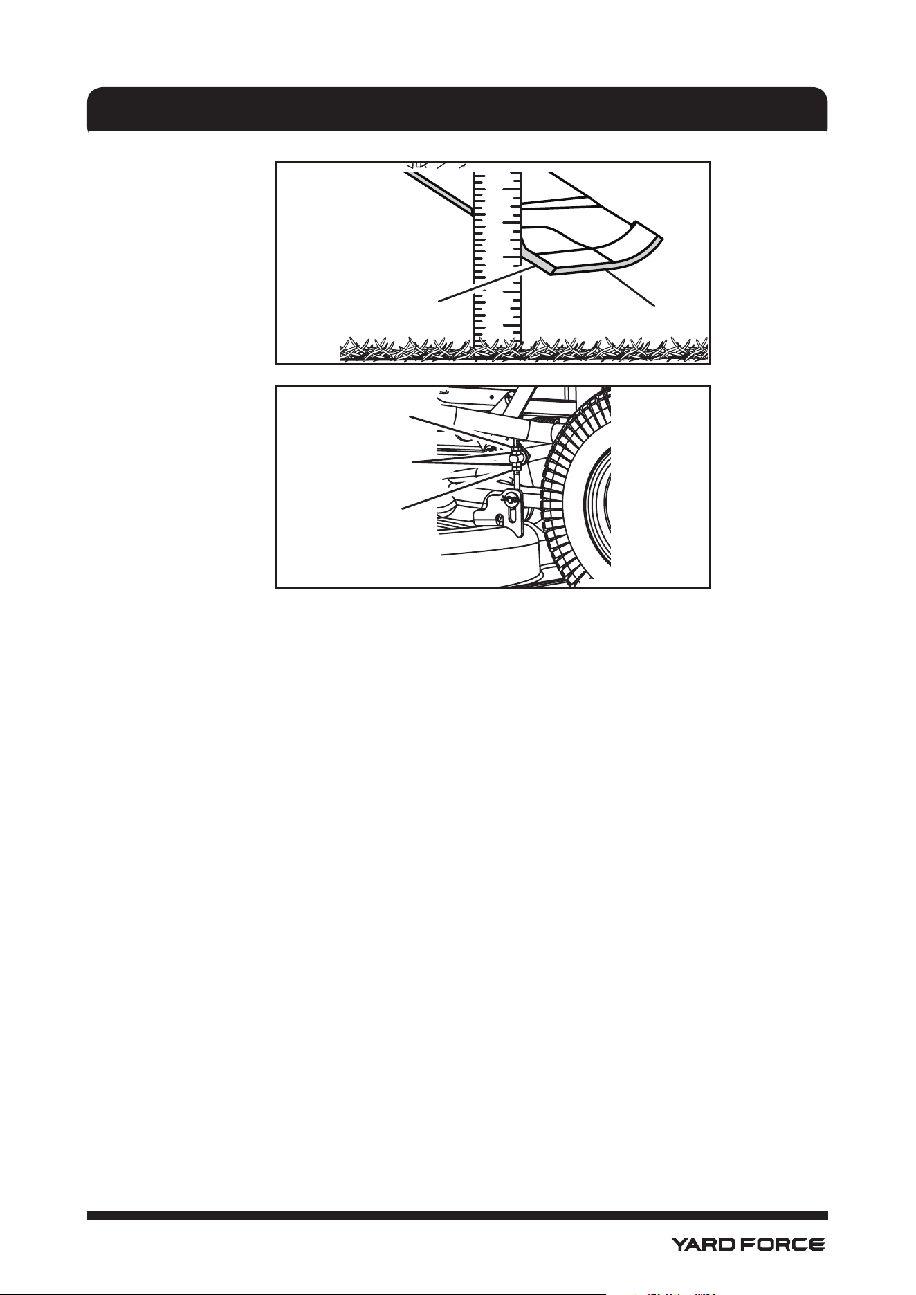
LEVELING THE CUTTING DECK (See Fig. 28&29)
If your lawn appears unevenly cut after using the mower, the cutting deck may need adjusting. Before
deciding that leveling the cutting deck is necessary, make sure tires are properly inated to the
recommended PSI when mowing. Over-inated or under-inated tires can affect the appearance of the cut,
and proper ination of the tires may be all that is needed to resolve uneven cutting issues.
NOTE: Always check side-to-side alignment and adjust as needed before measuring and adjusting front to
back.
Before beginning:
• Make sure direction control switch is in neutral (N) position and blade engage knob is down.
• Turn off the mower, remove the start key, and set the parking pedal.
• Raise the height of the cutting deck to its highest position.
To make side-to-side adjustment:
• Position the blades so that the ends point toward the sides of the mower.
• On the outside edge of each blade, measure the distance from the bottom edge of the side of the blade
to the ground. If the distance between the two sides is greater than 1/8 in., a side-to-side adjustment is
necessary.
• On the side you wish to adjust, loosen the jam nuts as shown.
• Turn the adjustment nuts clockwise to raise or counterclockwise to lower the side of the cutting deck.
Each full turn of the adjustment nut will change the deck height approximately 3/16 in.
NOTE: If raising the side, you will need to turn the top adjustment nut rst. If lowering, turn the bottom nut
rst.
• Measure again. Continue to adjust and measure until the difference between the distance on each side
is 1/8 in. or less.
• Proceed to front-to-back adjustment or retighten jam nuts to secure.
To make front-to-back adjustment:
NOTE: Always level the deck side to side before making a front to back adjustment.
• Position the blade nearest the side discharge chute so that the ends now point toward the front and
back of the mower.
• Measure the distance from the tip of the blade to the ground. For best results, the front tip of the blade
should be from 1/8 in. to 3/8 in. lower than the rear tip.
• If front-to-back adjustment is needed, turn the adjustment nuts clockwise to raise or counterclockwise
to lower the back of the cutting deck. Each full turn of the adjustment nut will change the deck height
approximately 1/8 in.
NOTE: Make sure to turn the adjustment nuts on both sides equally to prevent throwing the side-to-side
measurement off again.
• Measure again to verify the front tip is now 1/8 in. to 3/8 in. lower than the rear tip. If not, continue to
adjust and measure until they are.
• Without moving the adjustment nuts, retighten the jam nuts to secure the adjustment nuts in place.
MAINTENANCE AND STOARGE
Fig. 27
Adjustment Nut
35
1-866-902-9690
MAINTENANCE AND STOARGE
Jam Nut
Jam Nut
Adjustment
Nuts
Fig. 28
Fig. 29
1 2 3 4 5
Bottom Edge
Blade
Jam Nut
Jam Nut
Adjustment
Nuts
Fig. 28
Fig. 29
1 2 3 4 5
Bottom Edge
Blade
36
1-866-902-9690
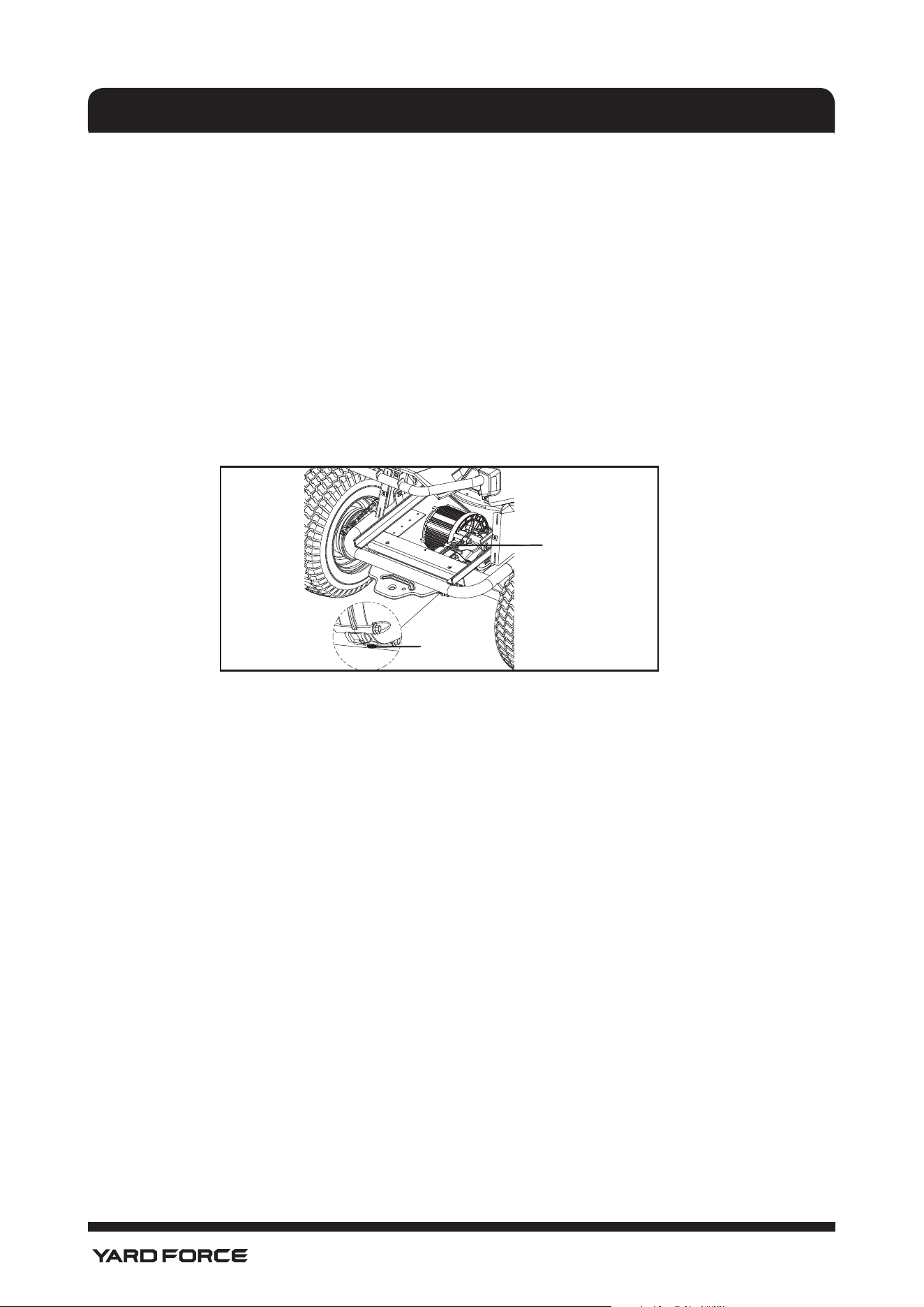
CHANGING/ADDING TRANSAXLE OIL (See Fig. 34)
NOTE: To access the transaxle, you must remove the battery tray from the mower. Refer to the section
Replacing the Batteries for instructions on how to fully extend the battery tray, then continue to extend the
tray all the way out of the mower so that you can access the transaxle. Once the battery tray is removed,
you may proceed with the steps below.
• Park the mower on a at, level surface. Allow the mower to cool before draining transaxle oil.
• Place a container underneath the transaxle oil drain plug.
• Remove the ll hole plug from the top of the transaxle.
• Remove the drain plug and drain the old oil.
• Clean the bottom drain plug, then reinstall plug and tighten securely.
• Pour 200cc new, clean GL4 80W/90 gear oil into the ll hole.
• Reinstall ll hole plug and tighten securely. Do not over- tighten.
• Reinstall the battery tray as described in Replacing the Batteries.
NOTE: Consult hazardous waste management guidelines in your area for the proper way to dispose of used
gear oil.
STORING THE MOWER
The following steps should be taken before storing the mower for the season.
• Remove any build-up of grass and leaves on or around the motor cover. Wipe the mower clean with a
dry cloth. Do not spray with a garden hose to clean.
• Plug the mower up to charge for the entire time of storage.
NOTE: If it is not possible to leave the mower charger connected during storage, charge the batteries at
least once a month during storage.
• Store mower in a clean, dry place that is inaccessible to children. Do not store near any appliance that
operates with ame such as a gas water heater, clothes dryer, or furnace.
NOTE: Do not leave the key in the mower during storage.
• If the mower must be stored outside, make sure it is covered completely to protect it from the elements.
• Keep away from corrosive agents such as garden chemicals and deicing salts.
PREPARING FOR USE AFTER STORAGE
The following steps should be taken before using the mower after it has been stored:
• Review maintenance chart.
• Fully charge the batteries.
• Check tire pressure and inate as needed.
• Briey drive the mower and check all systems and components to ensure they are functioning correctly.
BATTERY REMOVAL AND PREPARATION FOR RECYCLING
To preserve natural resources, please recycle or dispose of batteries properly.
This product uses lithium iron phosphate batteries. Local, state or federal laws may prohibit disposal of
batteries in ordinary trash.
Consult your local waste authority for information regarding available recycling and/or disposal options.
MAINTENANCE AND STOARGE
Fig. 34
Fill Hole Plug
Transaxle
Oil Drain Plug
37
1-866-902-9690
WARNING!
Upon removal, cover the battery’s terminals with heavy-duty adhesive tape. Do not attempt to
destroy or disassemble battery or remove any of its components. Lithium iron phosphate batteries
must be recycled or disposed of properly. Also, never touch both terminals with metal objects and/
or body parts as short circuit may result. Keep away from children. Failure to comply with these
warnings could result in re and/or serious injury.
From the date of purchase, this product has a Three-year Limited Warranty for personal, family or household
use, the battery and charger have a One-year Limited Warranty for personal, family or household use. For
warranty details, visit www.YardForceUSA.com or call (toll free) 1-866-902-9690 (US), or 1-833-818-4111
(CA).
MAINTENANCE SCHEDULE
Inspect Before
Each Use
Every
25
Hours
Every
50
Hours
Every
100
Hours
Before
Storage
Check Brake Operation X
Check Tire Pressure X
Check Safety Interlock
System
X
Check for Loose
Fasteners
X X
Clean Debris From
Mower
X X X
Check/Replace Mower
Blades
X X
Lubricate mower pivot
points, front axle pivot
and axle spindles, front
axle wheel bushings,
and deck pivot points.
X
Adding Oil to Transaxle X
Clean Battery
Terminals
X
NOTE: Maintenance should be performed more frequently when mower is used in dusty areas.
When mower has exceeded the maximum gures specied in the table, maintenance should still be cycled
according to the intervals of time or hours stated herein.
If you are unsure how to perform any of the maintenance items listed above, take the mower to an
authorized service center for assistance.
MAINTENANCE AND STOARGE
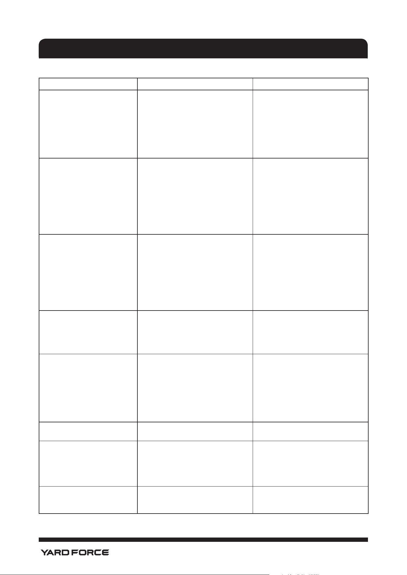
38
1-866-902-9690
TROUBLESHOOTING
Fault/Malfunction Cause(s) Solution(s)
Mower not starting.
1. Battery charge is low.
2. Charger is connected to mower.
3. Start key not installed or in the
OFF position.
4. Poor battery cable connections.
5. Battery overheat
1. Charge the battery.
2. Disconnect charger from mower.
3. Install start key and turn to ON
position.
4. Check/clean all battery
connections.
5. Let the mower cool down for a
while.
Mower won’t move.
1. Start key not installed or is in
OFF position.
2. Parking pedal is set.
3. Direction control switch is in
neutral (N).
4. Brake is depressed and/or
accelerator pedal is not pressed.
5. Charger is connected to mower.
1. Install start key and turn to ON
position.
2. Release parking pedal.
3. Place direction control switch
in desired direction (forward or
reverse).
4. Release the brake pedal and
press the accelerator.
5. Disconnect charger from mower.
Mower cutting grass unevenly.
1. Wet grass clippings sticking to
the underside of the deck.
2. Grass is too high.
3. Worn, bent, loose, or dull blade.
4. Mowing speed is too fast.
5. Unlevel deck
6. Tire pressure uneven or low.
1. Remove grass from deck, allow
grass to dry before mowing.
2. Mow once at a high cutting
height, then mow again at the
desired height.
3. Replace blade.
4. Mow at a slower speed.
5. Adjust the deck level
6. Check and adjust tire pressure.
Mower vibrating at higher
speed.
1. Blade is unbalanced, loose, or
excessively or unevenly worn.
2. Bent motor shaft.
1. Replace the blade.
2. Turn off the mower and remove
start key. Inspect for damage.
Have repaired by an authorized
service center before restarting.
Poor grass discharge.
1. Side discharge chute or opening
is plugged.
2. Grass is wet.
3. Mowing speed is too fast.
4. Grass is too high.
1. Clean side discharge chute and/
or opening.
2. Allow grass to dry before
mowing.
3. Mow at a slower speed.
4. Mow once at a high cutting
height, then mow again at the
desired height.
Motor stops while cutting.
1. Cutting height set too low.
2. Battery charge is low.
1. Raise the cutting height.
2. Charge the battery.
Blades do not rotate.
1. Battery charge is low.
2. Blade engage knob is down.
3. Operator is not fully seated.
4. Build-up of debris under mower.
1. Charge the battery.
2. Raise blade engage knob.
3. Sit down fully on the seat.
4. Clean underside of mower
housing.
Blades do not rotate while
moving in reverse.
1. Reverse mode option is off.
2. Blade engage knob is down.
1. Press reverse mode button to
activate.
2. Raise blade engage knob.
39
1-866-902-9690
Mower won’t reach full speed.
1. Battery charge is low.
2. Grass being cut is dense.
1. Charge the battery.
2. Mower will reduce drive speed
when blades sense increased
load from grass. This ensures a
quality cut.
Blades continue to turn after
operator leaves seat without
parking pedal set.
1. Safety interlock system is not
functioning correctly.
1. Ensure safety interlock system
seat plug is fully connected.
If blades still won’t stop, take
mower to authorized service
center for repair.
Headlights not working.
1. Headlights are off.
2. Headlights are damaged.
1. Press headlight button to turn
headlights on.
2. Replace headlights.
Battery will not charge. 1. Poor cable connections.
1. Check/clean all battery
connections.
CHARGER ERROR CODES
CODE MEANING SOLUTION
Yellow LED ON Standby /
Red LED ashing (1HZ) Charging /
Green LED ON Fully charge /
Red and Green LED ashing
alternately (2HZ)
Abnormal temperature of the
battery
Allow the battery to cool and retry
Red and Green LED ashing
alternately (1HZ)
Battery protection Unplug charger from wall outlet and
mower. Wait for LEDs to turn off,
then reconnect. If issue continues,
contact customer service
Yellow LED ashing Charge failure Unplug charger from wall outlet and
mower. Wait for LEDs to turn off,
then reconnect.
TROUBLESHOOTING

40
1-866-902-9690
USA WARRANTY
YARD FORCE LIMITED WARRANTY
Product Warranty
Please keep your original purchase receipt in a safe place as proof of purchase. Warranty coverage for
This product must be veried by the original purchase receipt. The warranty period begins on the day the
product was purchased from an authorized retailer of Yard Force products. Warranty coverage
only applies to the original purchaser and is not transferable. Warranty coverage is only provided on
products purchased and used in the USA and Puerto Rico from authorized Yard Force retailers. Products
purchased or used outside of the USA and Puerto Rico are not covered by this warranty.
(3) Three-Year Warranty from The Date of Purchase – Drivetrain and Chassis
(1) One-Year Warranty from The Date of Purchase – Battery and Charger
The YF56vRX-RER38-Li50 has a Three-Year Limited Warranty from the date of purchase against
manufacturer defects for residential use only, excluding the battery and charger. Commercial use voids
the warranty. This warranty does not cover accidental damage, unreasonable use, normal wear and tear,
neglect or non-compliance with the Operating, Safety and Maintenance Instructions. All service, outside of
normal maintenance as described in this manual, must be done by an authorized service technician. Any
unauthorized service or changes to the original conguration of this product will void the warranty. All parts
and accessories used on and with this product must be manufacturer/or and authorized by Merotec Inc.
(90) Ninety-Day Warranty – Accessories
The accessories included with the YF56vRX-RER38-Li50; including the knobs, hitch pins, blades, tires,
brakes, etc., and other similar parts are warranted against manufacturer defects for residential use only for a
period of 90 days from date of purchase.
Warranty does not cover loss of use or other consequential damages arising from any of the above, nor
does it cover repairs made or attempted by unauthorized persons. This warranty is void if the product
is used for commercial, rental or industrial purposes. Certain parts, attachments and accessories are
subject to normal wear and tear and are excluded from the warranty.
Service and Warranty Claims Process
Contact the Yard Force Customer Service toll-free at (866) 902-9690 Monday-Friday between 8:30 AM
and 5:00 PM Eastern Time for service and warranty support.
Yard Force USA Service Support agents can help you troubleshoot problems over the phone to get
you back up and running as quickly as possible. In the situation where service or warranty inspection is
needed, please follow these steps:
1. Contact Yard Force Customer Service at (866) 902-9690 or [email protected] Monday-
Friday between 8:30 AM and 5:00 PM Eastern Time.
2. Send in proof-of-purchase and serial number (if applicable) to conrm warranty coverage.
3. If service or a warranty evaluation is requested, Yard Force USA will provide an RGA number that should
be used in all communications with Yard Force USA and if necessary, a list of local authorized service
centers to bring your lawn mower to for evaluation and repair.
4. All shipments to Yard Force USA must have an RGA number. Any shipment received that does not have
an RGA number clearly marked on the outside of the box will be refused.
5. All shipments must be sent pre-paid; Yard Force USA does not pay for any shipping or transportation
costs for service or warranty evaluation. Yard Force USA is not responsible for any packages that are
lost by carrier. We recommend that shipments are made by a carrier that provides tracking and delivery
conrmation.
For more information or to ask questions, please call toll-free (866) 902-9690 or [email protected]
Monday-Friday between 8:30 AM and 5:00 PM Eastern Time.
WARRANTY

41
1-866-902-9690
43
CANADA WARRANTY
YARD FORCE LIMITED WARRANTY
Product Warranty
Please keep your original purchase receipt in a safe place as proof of purchase. Warranty coverage for
this product must be veried by the original purchase receipt. The warranty period begins on the day the
product was purchased from an authorized retailer of Yard Force products. Warranty coverage
only applies to the original purchaser and is not transferable. Warranty coverage is only provided on
products purchased and used in the Canada from authorized Yard Force retailers. Products purchased or
used outside of the Canada are not covered by this warranty.
(3) Three-Year Warranty from The Date of Purchase – Drivetrain and Chassis
(1) One-Year Warranty from The Date of Purchase – Battery and Charger
The YF56vRX-RER38-Li50 has a Three-Year Limited Warranty from the date of purchase against manufacturer
defects for residential use only, excluding the battery and charger. Commercial use voids the warranty.
This warranty does not cover accidental damage, unreasonable use, normal wear and tear, neglect or
non-compliance with the Operating, Safety and Maintenance Instructions. All service, outside of normal
maintenance as described in this manual, must be done by an authorized service technician. Any
and accessories used on and with this product must be manufacturer/or and authorized by Merotec Inc.
(90) Ninety-Day Warranty – Accessories
The accessories included with the YF56vRX-RER38-Li50; including the knobs, hitch pins, blades, tires, brakes,
etc., and other similar parts are warranted against manufacturer defects for residential use only for a period
of 90 days from date of purchase.
Warranty does not cover loss of use or other consequential damages arising from any of the above, nor
does it cover repairs made or attempted by unauthorized persons. This warranty is void if the product
is used for commercial, rental or industrial purposes. Certain parts, attachments and accessories are
subject to normal wear and tear and are excluded from the warranty.
Service and Warranty Claims Process
Contact the Yard Force Customer Service toll-free at 1-833-818-4111 Monday - Friday between 8:30 AM and
4:30 PM Eastern Time for service and warranty support.
Yard Force Canada Service Support agents can help you troubleshoot problems over the phone to get
you back up and running as quickly as possible. In the situation where service or warranty inspection is
needed, please follow these steps:
1. Contact Yard Force Customer Service at 1-833-818-4111 Monday - Friday between 8:30 AM and
4:30 PM Eastern Time.
2.
3. If service or a warranty evaluation is requested, Yard Force Canada will provide an RGA number that
should be used in all communications with Yard Force Canada and if necessary, a list of local authorized
service centers to bring your lawn mower to for evaluation and repair.
4. All shipments to Yard Force Canada must have an RGA number. Any shipment received that does not
have an RGA number clearly marked on the outside of the box will be refused.
5. All shipments must be sent pre-paid; Yard Force Canada does not pay for any shipping or transportation
costs for service or warranty evaluation. Yard Force Canada is not responsible for any packages that are
lost by carrier. We recommend that shipments are made by a carrier that provides tracking and delivery
For more information or to ask questions, please call toll-free 1-833-818-4111 or [email protected]
Monday - Friday between 8:30 AM and 4:30 PM ET.
WARRANTY
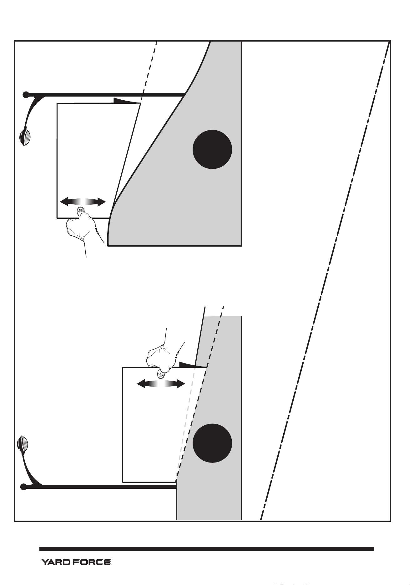
42
1-866-902-9690
15˚ Slope
15˚ Line
15˚ Slope
www.YardForceUSA.com
1-866-902-9690 (US)
1-833-818-4111 (CA)
Scan Code to connect with Yard Force Support
Need Help?
Please do not return the product to your place of purchase yet. We’re here to help and take care
of all your needs.
Contact our customer service department for help with:
• Product assembly or use
• Missing or damaged parts
• Troubleshooting
• Replacement parts and accessories
You can submit a support request by scanning the QR code on this page, or by visiting:
www.YardForceUSA.com/contact-support
Register your product today to maintain warranty coverage and stay up to date with
information on the use, care, maintenance and service of your product.
Register online today at:
www.yardforceusa.com/product-registration
Merotec Inc.
3655 Kennesaw North Industrial Parkway
Kennesaw, GA 3014
4
Copyright © 2023 Merotec Inc.
Made in China
Part Number: YF56vRX-RER38-Li50-MAN-B
2301