INSTALLATION & OPERATION
INSTRUCTIONS
GYROS GAS - LINE V
DG20V
ETL CERTIFICATION
VISVARDIS SA
CATERING EQUIPMENT

2
The manufacturing company, has no responsibility if the device broke up because of bad
usage or because of not following the operation & installation instructions to the letter.
Please read very carefully the operation instructions!
This device has been checked & adjusted for operation with Nat Gas (Gas A) &
Pressure 7 i.w.c. (17.4 mbar).
Seal of the authorized agent
3
1. INSTALLATION
1.1 The purchaser should post in a prominent location instructions to be followed in the event the
user smells gas. This information shall be obtained by consulting the local gas supplier.
1.2 The appliance area should be kept free and clear from combustibles.
1.3 The device must be located in a very well ventilated area, under an air-extractor so that the
absorption of the gases that are generated during its function to be fully achieved.
1.4 The device must be located at least 20" inches (=51cm) away from combustible materials
(back and both sides) and at least 20" inches (=51cm) (at the back) away from an
incombustible wall in order to let the service operate on the unit.
1.5 The minimum ambient temperature for safe use is 5°C or 41°F.
1.6 The manual instructions should be retained for future reference.
1.7 The installation, the connection and the calibration of the device or the transformation of the
device for another type of gas, must be done only by authorized technicians always according
to the local codes, or in the absence of local codes, with the
National Fuel Gas Code, ANSI
Z223.1/NFPA 54
, or the
Natural Gas and Propane Installation Code, CSA B149.1
, as applicable,
including:
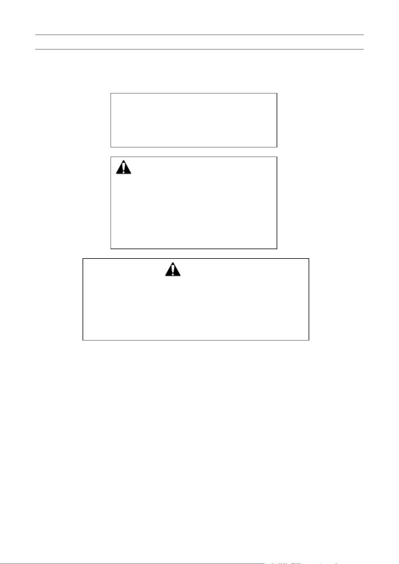
FOR YOUR SAFETY
Do not store or use gasoline or other
flammable vapors and liquids in the
vicinity of this or any other appliance.
⚠ WARNING: Improper installation,
adjustment, alteration, service or
maintenance can cause property
damage, injury or death. Read the
installation, operating and
maintenance instructions thoroughly
before installing or servicing this
equipment.
⚠ WARNING
Electrical Grounding Instructions
This appliance is equipped with a three-prong
(grounding) plug for your protection against shock
hazard and should be plugged directly into a properly
grounded three-prong receptacle. Do not cut or
remove the grounding prong from this plug.
4
i. The appliance and its individual shutoff valve must be disconnected from the gas supply
piping system during any pressure testing of that system at test pressures in excess of 1/2
psi (3.5 kPa).
ii. The appliance must be isolated from the gas supply piping system by closing its individual
manual shutoff valve during any pressure testing of the gas supply piping system at test
pressures equal to or less than 1/2 psi (3.5 kPa).
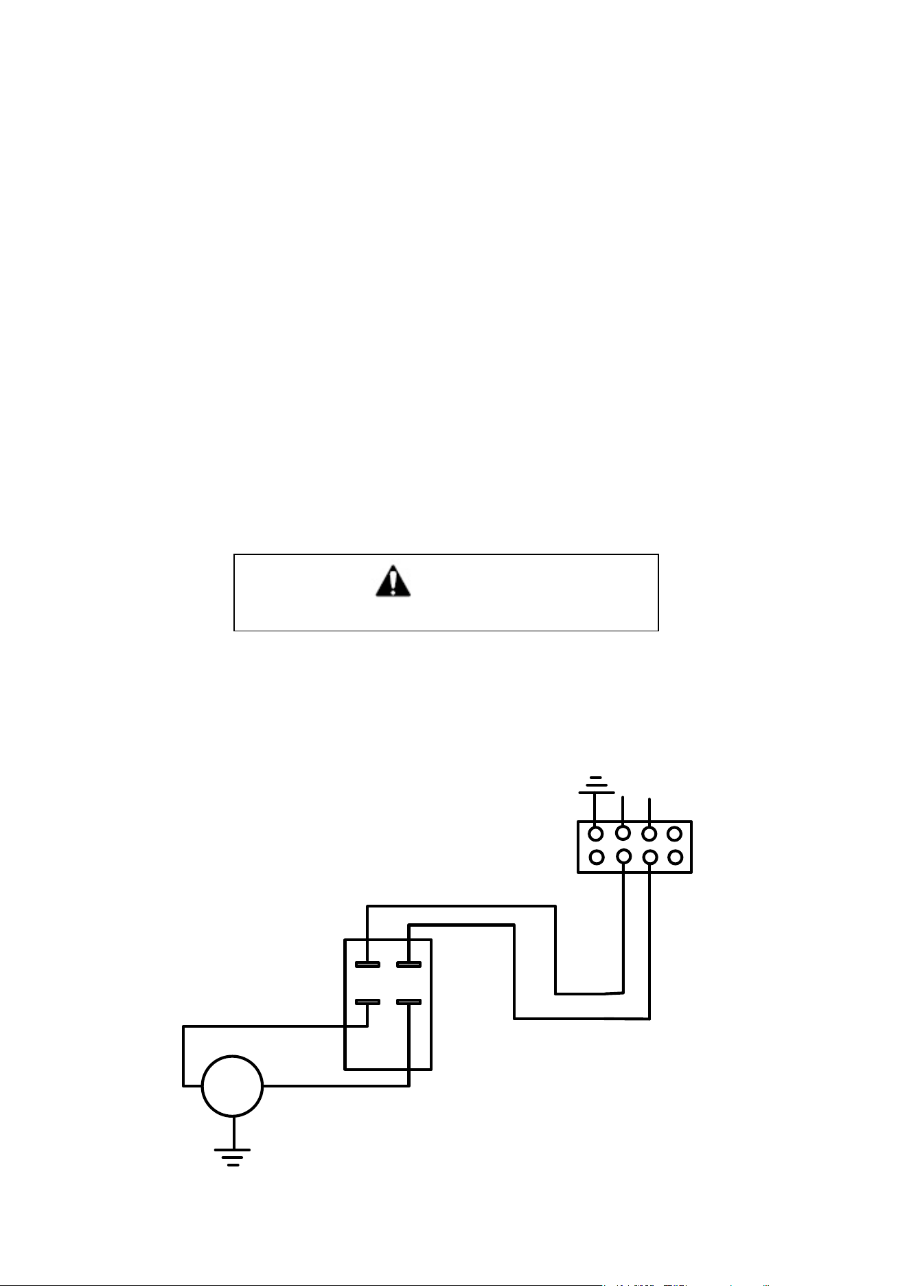
1.8 The appliance, when installed, must be electrically grounded in accordance with local codes, or
in the absence of local codes, with the
National Electrical Code, NFPA 70
, or the
Canadian
Electrical Code, CSA C22.2
, as applicable.
1.9 Remove carefully the plastic coverage from all parts of metallic surface of the device ahead,
rear & on the sides so as to be clear without plastic residues. For better cleaning use gasoline
with oil or petrol.
1.10 The attachment of the device with the gas supply must be done with the appropriate metallic
tube without any junctures, or with a special flexible metallic tube according to the laws & the
ordinances, which are valid.
1.11 It is necessary to install a switch (sluice), between the device and the gas supply which must
be closed by the operator when this specific device is not in use.
1.12 After the completion of all the above, check out all the connections to make sure that there is
no leak. For that check, use only a special spray for that purpose.
ELECTRICAL DIAGRAM – 115V
L
N
M
BASE WITH MOTOR
AND ELECTRICAL
CONNECTIONS
GROUND
MOTOR
SWITCH
GROUND
CONNECTOR
⚠ WARNING
Never use flame for this test.

5
TECHNICAL DATA - TABLE 1
MODEL DG 12V DG 16V DG 20V
Total Rate (Btu/hr)
Nat Gas 72000 96000 115000
LP 78000 104000 130000
Single Rate (Btu/hr)
Nat Gas 12000 12000 12000
LP 13000 13000 13000
Gas Consumption
Nat Gas (ft
3
/h)
76 101 126
LP (lb/h) 3.55 4.74 5.93
Nat Gas (Gas A)
Diam. injectors
(mm)
1.5 X 6 1.5 X 8 1.5 X 10
LP (Gas E)
Diam. injectors
(mm)
1.0 X 6 1.0 X 8 1.0 X 10
PRESSURE (i.w.c.)
Nat Gas (Gas A) 7 7 7
LP (Gas E) 11 11 11
Neccesery air for combustion ft
3
34.2 45.6 55
TECHNICAL CHARACTERISTICS - TABLE 2
MODEL DIMENSIONS (mm) BURNERS POWER
RACCOR
DS GAZ
No
Nat Gas
(Btu/hr)
Natl gas
(ft
3
/h)
LP
(lb/h)
(inch)
DG 12V 6 72000 76 3.55
1
/
2
-14 NPT
DG 16V 8 96000 101 4.74
1
/
2
-14 NPT
DG 20V 10 115000 126 5.93
1
/
2
-14 NPT
CONSUMPTION
570 X 720 X 820
570 X 720 X 980
570 X 720 X 1160
(LxPxH)
2. CONTROL & ADJUSTMENT OF PRESSURE
2.1 This device is regulated and controlled in order to function with Nat Gas (Gas A), with pressure
7 i.w.c. (17.4 mbar).
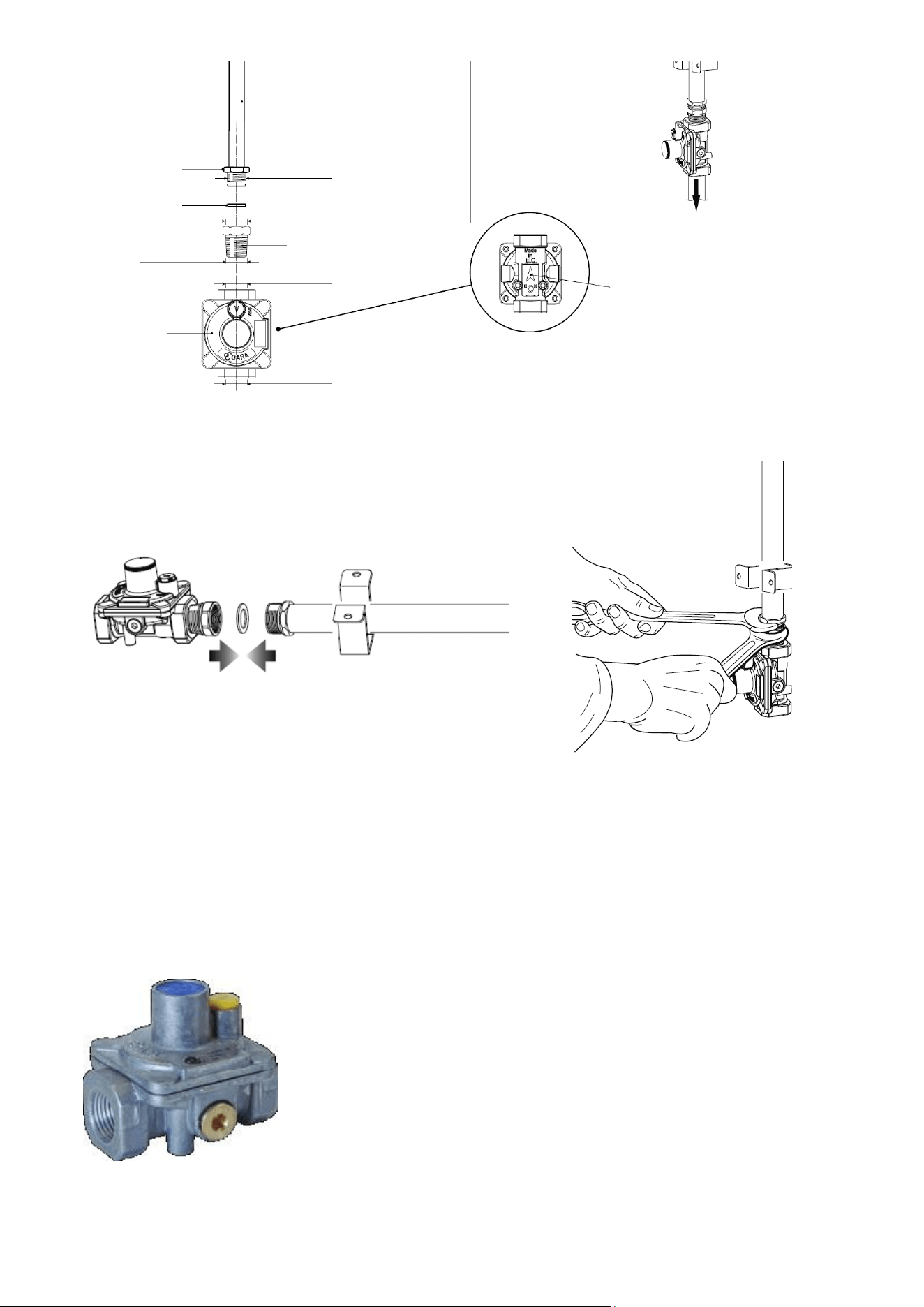
A regulator should be installed in order to achieve right and strong pressure. In order to install a
regulator of pressure follow the instructions below.
6
Fig. 1: Installation of pressure regulator
The pressure regulator must have a pressure adjustment range to allow adjustment to the manifold
pressure on the appliance rating plate 2.5" to 12" i.w.c.
The proposed pressure regulators are type 96 and 97.
Fig. 2: Pressure regulator
Extension
pipe
1/2” G cylindrical
(ISO 228-1) male
Extension pipe
male pipe fitting
1/2" G cylindrical
(ISO 228-1) female
1/2” NPT
(conical) male
Pressure
regulator
Connector
1/2" NPT female
1/2" NPT female
To mains connection
IMPORTANT!
Check the correct positioning of the gas regulator.
The arrow on the back of the gas regulator must
be oriented towards the connector.
Gasket
Joint
Arrow
Joint
IMPORTANT !
Use two wrenches to tighten the connection.
7
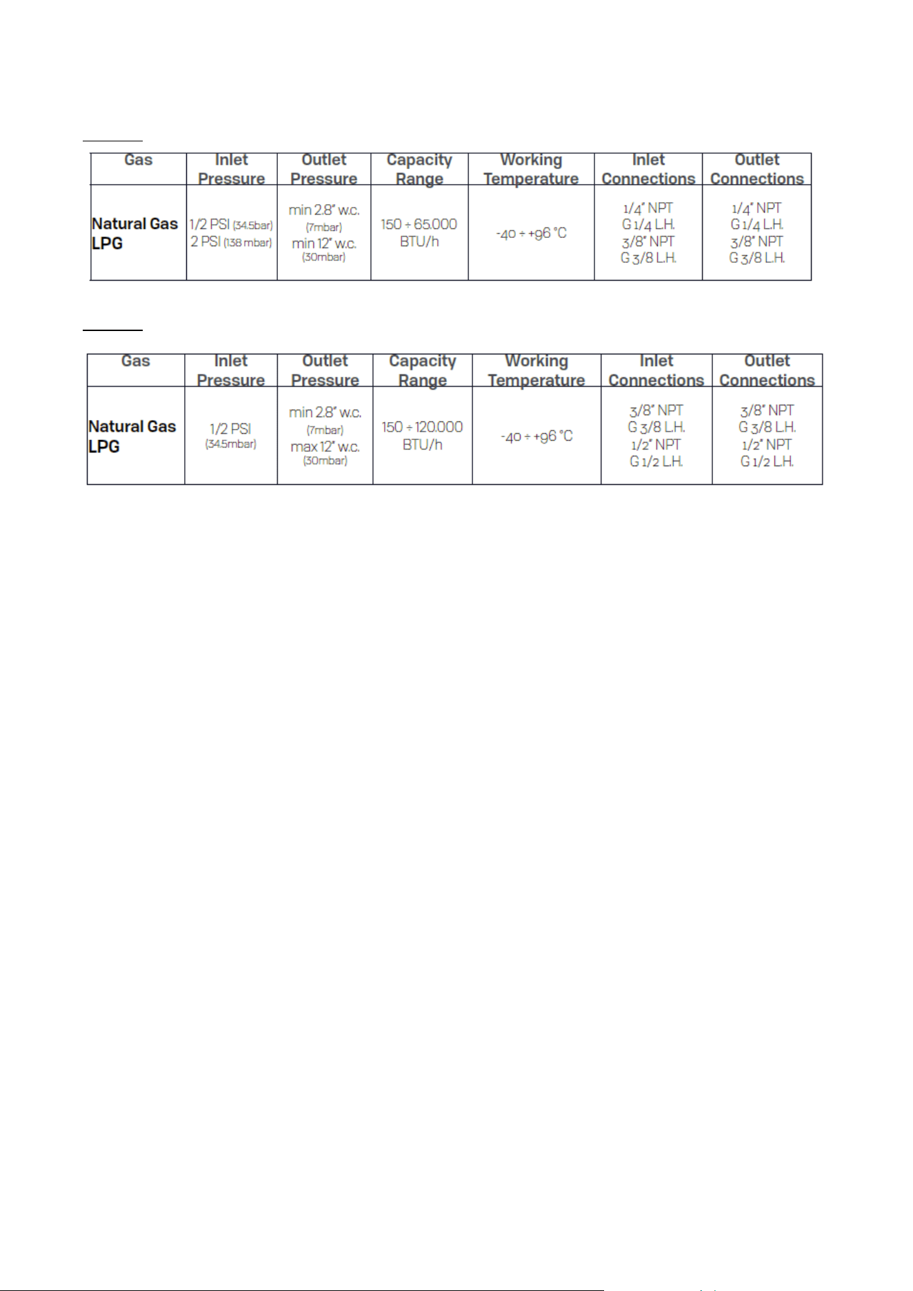
Technical features
Type 96
Type 97
Notice!
The pressure regulator installed must be listed by a nationally recognized testing agency.
In order to operate this device with a different gas, it is necessary to regulate the device with the
type of gas that is going to be used.
2.2 The pressure that corresponds to different types of gas is shown at Table 1.
7 i.w.c. (17.4 mbar) for natural gas (Nat Gas (Gas A)).
11 i.w.c. (27.4 mbar) for propane (Liquid Propane: LP (Gas E))
See at Table 1.
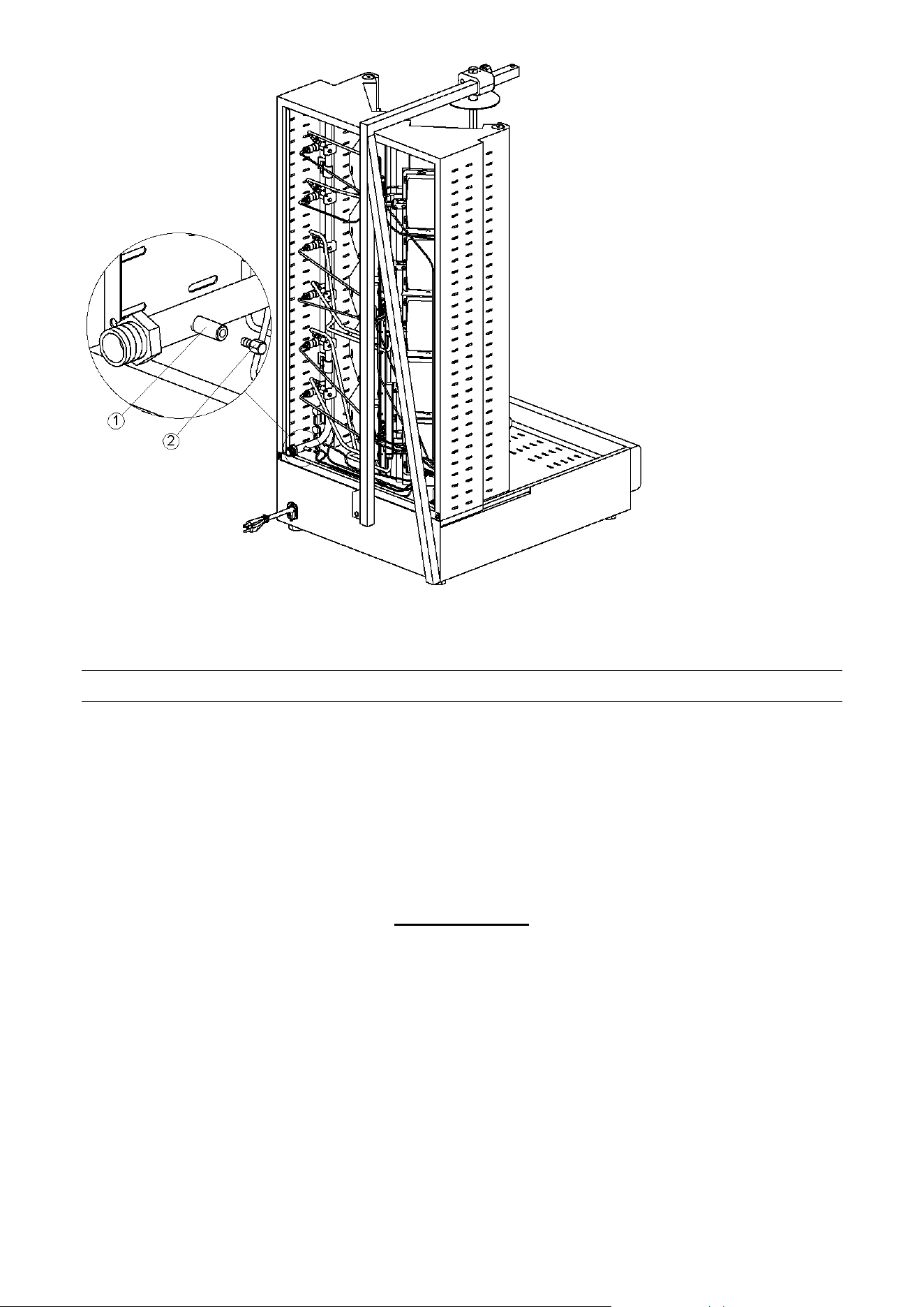
2.3 STAGES OF PRESSURE CONTROL (Fig. 3)
In order to control the pressure use a manometer with a division at least 0, 1 mbar.
Unscrew the insulate bolt (2) of the pressure control point (1).
Connect the manometer at the pressure point (1).
Check that the pressure of the device is the appropriate for the type of gas you are going to use.
Remove that manometer.
Screw the insulate bolt (2) at the pressure control point (1).
Check for leak!
8
Fig. 3: Pressure control
3. CONVERSION TO DIFFERENT TYPES OF GAS
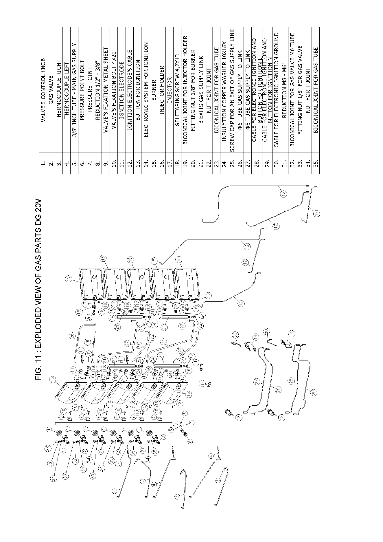
3.1 In order to achieve main transformation from Nat A to LP E gas you must change the injector
of the burner and convert your pressure regulator. The size of the injector, which corresponds to
the type of the gas, appears at Table - 1.
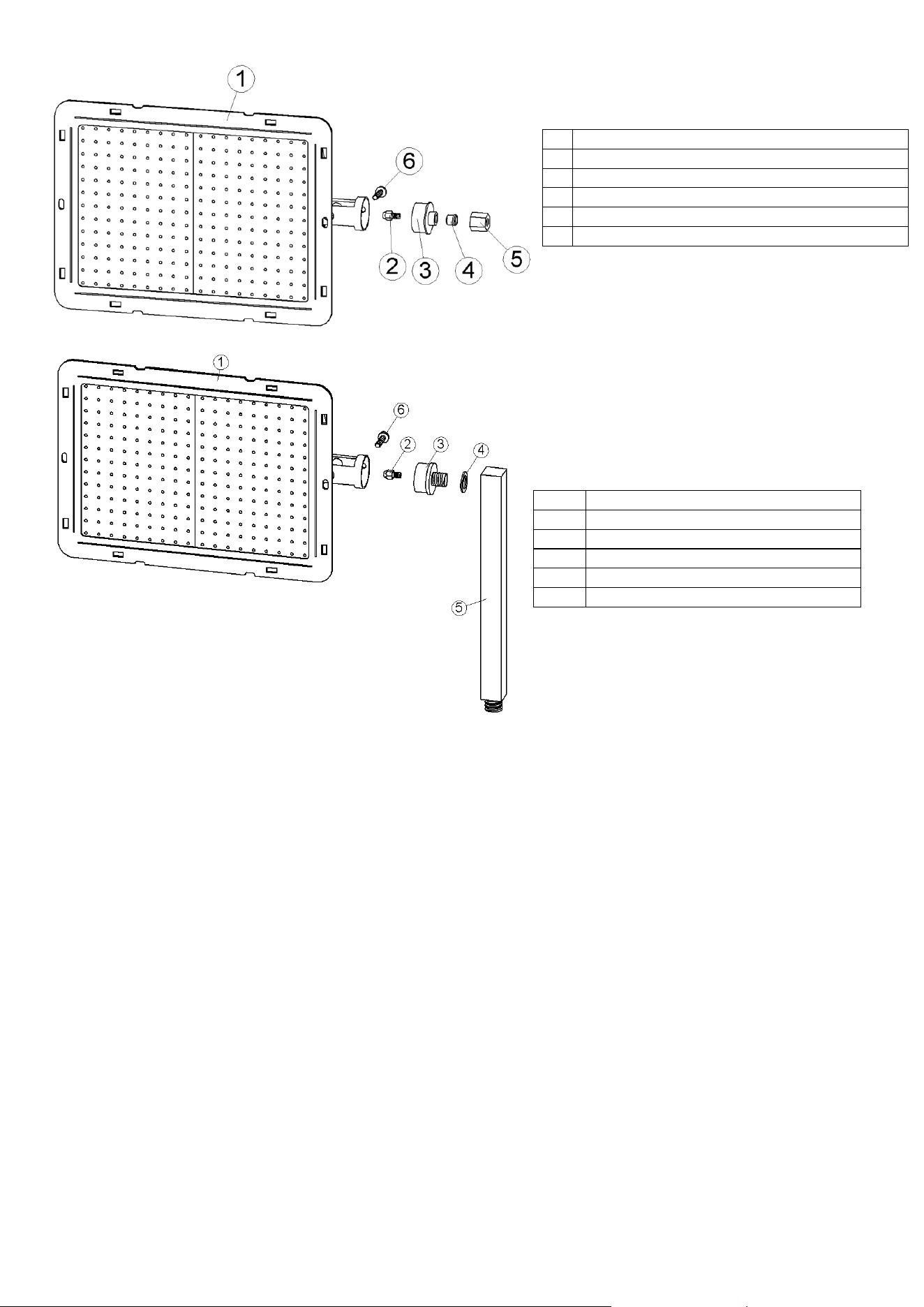
3.2 CHANGING THE MAIN BURNER’S INJECTOR (Fig. 4)
In order to change the injector (Νο 2, Fig. 4), unbolt it and bolt the appropriate injector. In every
appliance you will find in a socket the appropriate injectors for LP gas E.
ATTENTION !!!
After changing the injector make a leak check.
9
Fig. 4: Changing burner’s injector
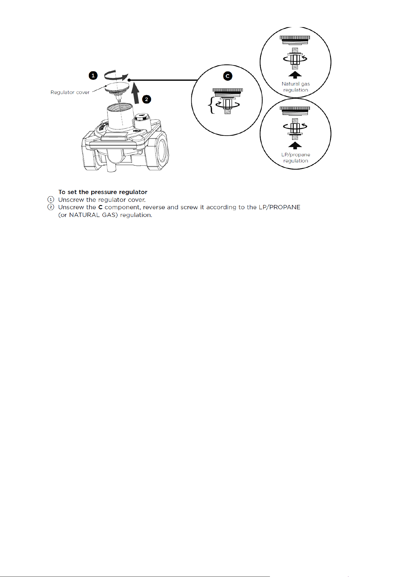
3.3 CONVERTING THE PRESSURE REGULATOR TO ΤΗΕ APPROPRIATE TYPE OF
GAS
In order to convert your pressure regulator to another type of gas follow the instructions:
1.
BURNER
2.
BURNER’S INJECTOR
3.
INJECTOR HOLDER
4.
BICONINCAL JOINT FOR Ø6 GAS TUBE
5.
FITTING NUT 1/8" FOR BURNER
6.
SELFTAPING SCREW 4,2X13
1.
BURNER
2.
BURNER’S INJECTOR
3.
INJECTOR HOLDER
4.
COPPER WASHER 10 X 16 X 1
5.
3 EXITS GAS SUPPLY LINK
6.
SELFTAPING SCREW 4,2X13
10
Fig. 5: Converting pressure regulator to other type of gas
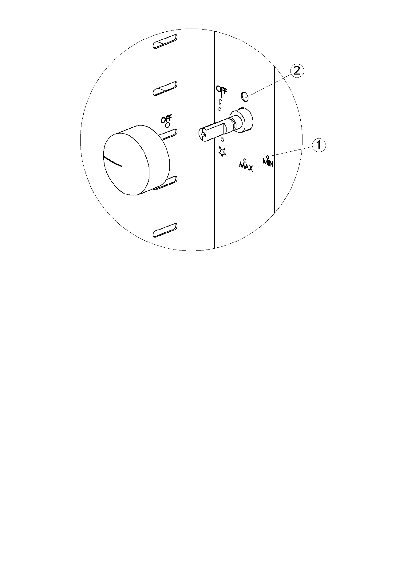
3.4 REGULATION OF THE SMALL FLAME (Fig. 6)
Turn on the main burner according to the instructions, turn the knob at the position MIN of the
little flame (Νο 1, Fig. 6). Make sure that, at the position MIN, burner’s flame is still alight, even
during rapid turning of the knob from the MAX to the MIN.
In case that at the position MIN, burner’s flame dies down, or if the flame is very strong then do
the following steps:
Keep the knob at the position MIN
Pull off the knob of the gas valve and with a small screwdriver regulate the screw of the gas
valve, which is located behind the hole (No 2, Fig. 6).
When you turn the bolt right you reduce the intensity of the flame, & when you turn it left you
make the flame stronger.
Regulate the intensity of the flame at your will. Then put back the black knob of the gas valve
at its former position.
3.5 FINAL FUNCTION CHECK
Turn the device on following the instructions on the next pages.
Check with a special spray if there is a leak.
Check the intensity of the burner’s flame turning the knob of the gas valve from the little to the
big flame.
Make sure that during the ignition the flame is widespread everywhere in the burner and that it
has a steady deep blue color.
11
Fig. 6: Regulation of the intensity of flame
12
4. OPERATION INSTRUCTIONS
ATTENTION !!!
This device is designed only for professional use & must be used exclusively by experienced &
well-trained personnel.
The device must be constantly supervised during its usage.
4.1 BEFORE TURNING THE DEVICE ON
We would like to advise you to clean thoroughly the GYROS before to begin to use the machine.
See the paragraph 4.9 “Instructions for the cleaning of this device”.
4.2 OPEN UP THE GAS SUPPLY
4.3 PROPER WAY TO IGNITE THE BURNERS
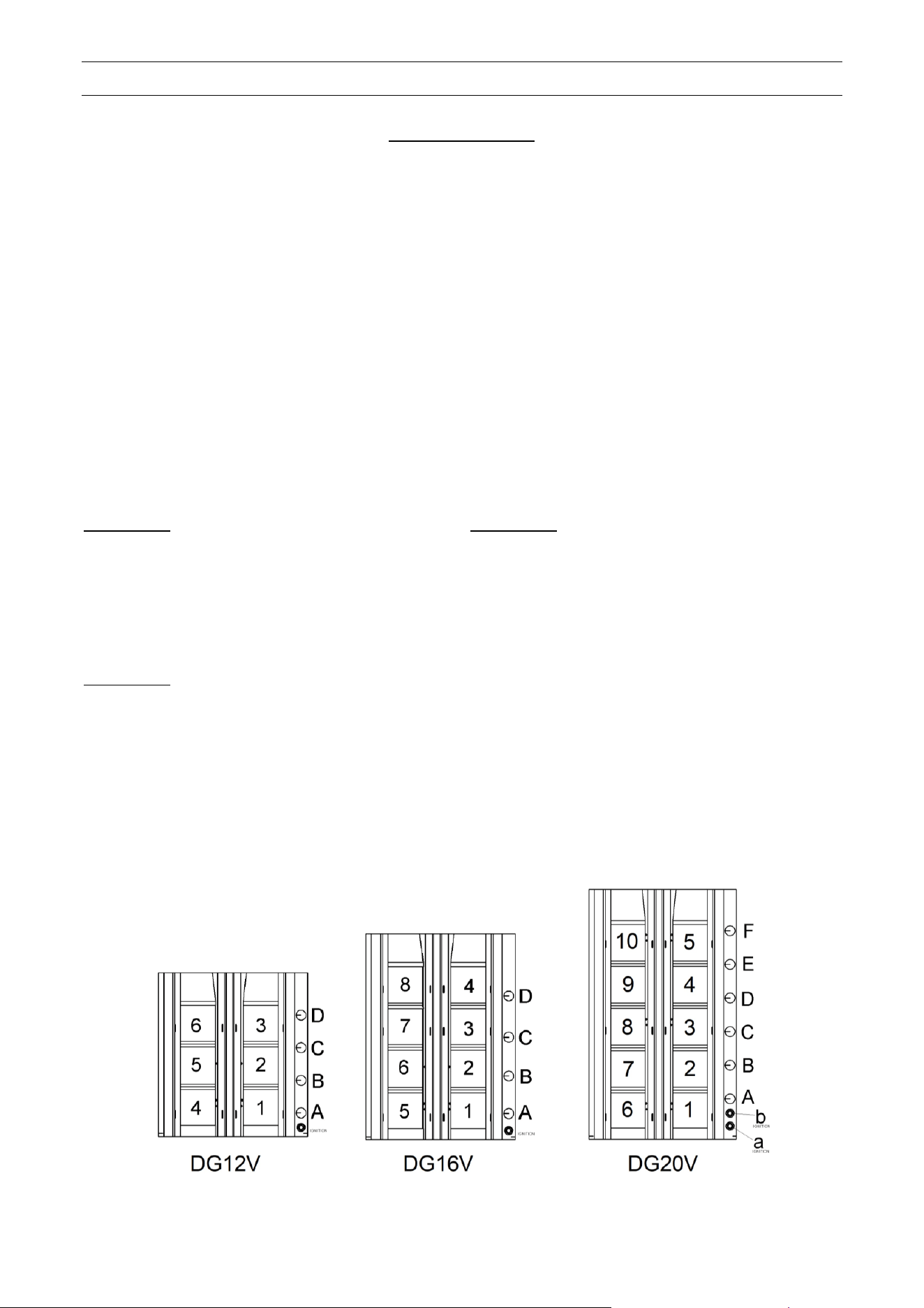
The correlation between buttons and burners for both models (DG 12V, DG16V, DG 20V) can be
seen in Fig. 7.
For DG 12V
Knob Α: ignites burners 1, 2
Knob Β: ignites burners 4, 5
Knob C: ignites burner 3
Knob D: ignites burner 6
Button: ignites all burners
For DG 16V
Knob Α: ignites burners 1, 2
Knob Β: ignites burners 5, 6
Knob C: ignites burners 3, 4
Knob D: ignites burners 7, 8
Button: ignites all burners
For DG 20V
Knob Α: ignites burners 1, 2
Knob Β: ignites burners 6, 7
Knob C: ignites burners 3, 4
Knob D: ignites burners 8, 9
Knob E: ignites burner 5
Knob F: ignites burner 10
Button a: ignites burners 6, 7, 8, 9, 10
Button b: ignites burners 1, 2, 3, 4, 5
Fig. 7: Correlation between knobs, buttons and burners

13
4.4 IGNITION OF THE BURNER (Fig. 8)
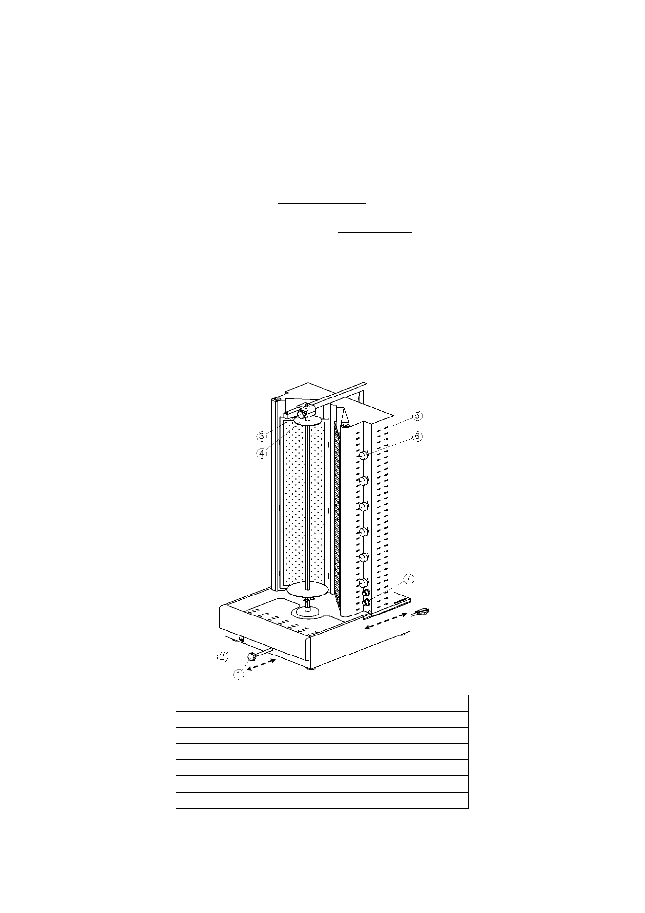
It is recommended the burners to be switched on beginning from the bottom to the top and not the
other way round for better roasting. In order to switch on a burner press slightly inboard the knob
of the gas valve (No 6, Fig. 8) and turn anticlockwise (left), until the position that is the reading of
MAX. At this position keep well pressed the button while at the same time you are pressing the
corresponding button of the lighter (No 7, Fig. 8) according of the instructions of paragraph 4.3.
At the first time of the operation of the device you may have to repeat the previous procedure so
as to achieve the vaporization of the air that exists inside the burner.
When the burner ignites keep the button pressed inside for 10 seconds so that the thermocouple to
be heated, so that it keeps the flame of the burner on.
In order to reduce the intensity of the burner’s flame turn the knob of the gas valve at the position
MIN of the little flame.
4.5 TURNING THE BURNER OFF
Always, the burners have to be switched off beginning from the top to the bottom.
The burner would stop functioning when you turn the gas valve right (clockwise), until the position
that the fire of the burner stops. By this way you stop the gas supply to the burner.
4.6 PUTTING THE INOX SPIT (Fig. 9)
The device has to be switched off during the time that you place the spit with the meat on the
machine.
You place the spit with the meat inside the bottom support base (Νο 5, Fig. 9) and at the same
time you pull up the top round disk (No 4, Fig. 8) you place the spit in its place and then you pull
down the top round disk.
ATTENTION !!!
Before to operate your machine do a double check that the spit is well inside its position and
none of the top or bottom spit´s supports move.
4.7 DISTANCE REGULATION FROM THE BURNERS
In order to regulate the distance of the burners from the spit you have to pull out the
movement mechanism (No 1 Fig. 8) the main body will move back or in front at the distance
you wish.
You can as well regulate the distance of the spit by unscrewing the top fixing handle (No 3, Fig.
8) and moving the top disk back or in front to the desired position.
4.8 MOTOR´S FUNCTION
In order to begin motor´s function you have to push the button of the motor (No 2, Fig. 8) at the
position ON.
4.9 INSTRUCTIONS FOR THE CLEANUP OF THE DEVICE (Fig. 9)
In no case should you clean the device with a flow of water or with a potent acid.
The use of acid might inflict rust to the metallic surfaces.
The cleanup must be done only when the device is cold and with disconnected the power supply.
It is necessary to clean the device after each operation.
You can clean the device with a sponge using only special products for stainless surfaces.
14
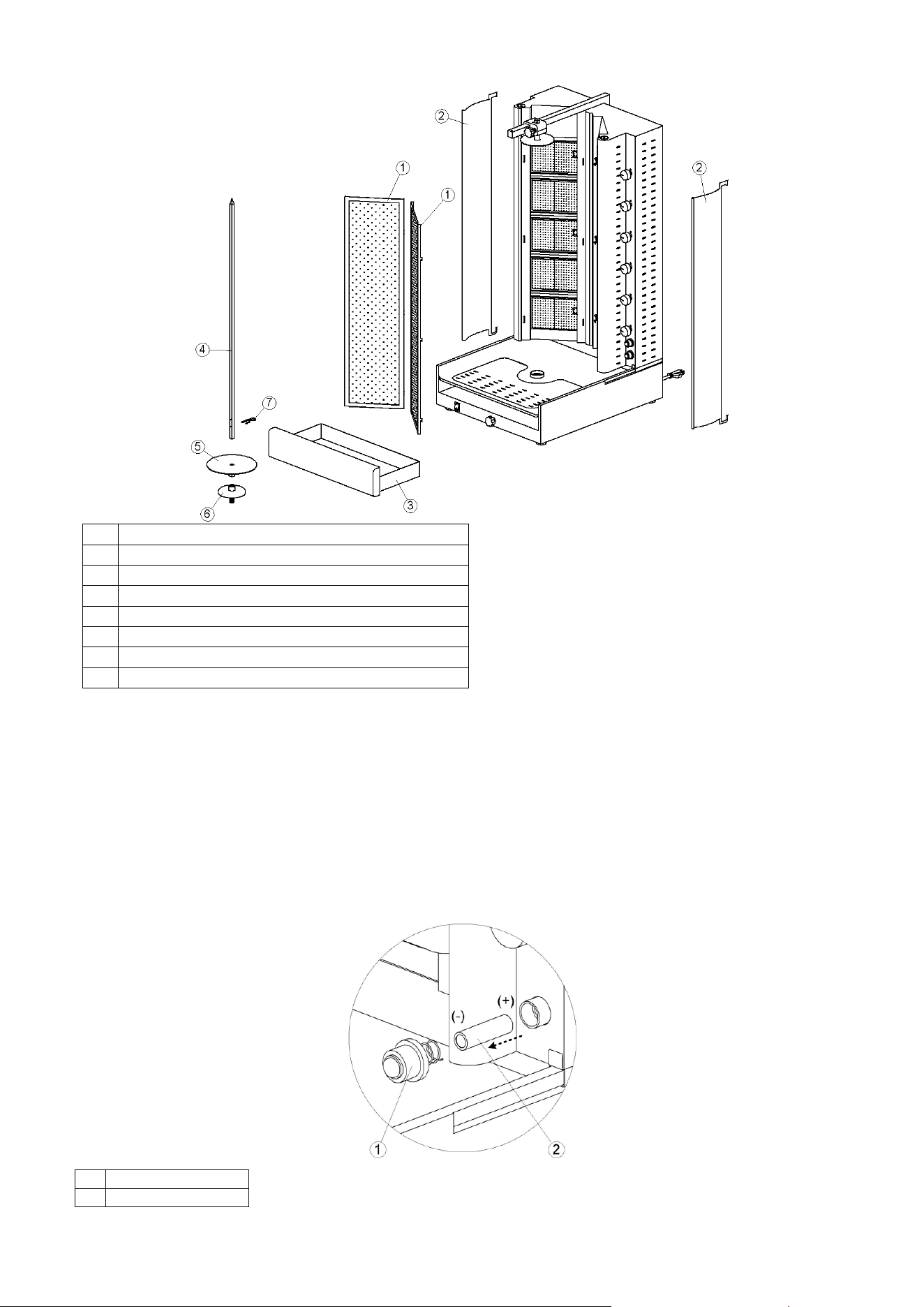
You can first put off and clean all the movable parts of your machine (See Fig. 9).
Remove the spit (No 4, Fig. 9).
Remove the doors (No 2, Fig. 9) if exist.
Remove the burners’ protection net (No 1, Fig. 9).
Remove the spit’s support mechanism (No 5 & 6, Fig. 9).
Pull out the collector (No 3, Fig. 9).
Wash and clean the moveable parts of your appliance and after set them back to their positions.
WARNING !!!
Do not direct jets of water, against the appliance to prevent any water entering in the components.
No water with or without pressure should be used underneath the machine where is the motor
and all the electric connections.
4.10 MAINTENANCE
The correct operation of your appliance is guaranteed only if these instructions are followed
carefully.
Any repairs or maintenance operations must be performed only by qualified technicians.
We recommend having the appliance controlled at least once a year, for this purpose it is advisable
to apply for a service contract.
Keep the thermocouple constantly clean and treat them carefully.
1.
Body Movement Mechanism (front – back)
2.
ΟΝ – ΟFF Button
3.
Top Fixing Handle
4.
Top Round Disk
5.
Main Body of Gyros Gas
6.
Gas Valve Knob
7.
Button for lighter
Fig. 8 Description of main parts of DGV
15
DESCRIPTION
1.
BURNER'S PROTECTION NET
2.
DOOR
3.
COLLECTOR
4.
INOX SPIT
5.
LOWER DISK OF INOX SPIT
6.
LOWER SUPPORT MECHANISM OF INOX SPIT
7.
PIN OF INOX SPIT
Fig. 9 Removable components of DGV
4.11 INSTRUCTIONS FOR CHANGING THE BATTERY
When the lighter does not ignite then you need to replace the battery. Follow the next simple steps
in order to replace the battery (Fig. 10).
Unscrew the lighter’s knob (No 1, Fig. 10).
Remove the battery (No 2, Fig. 10) and replace it with a new one.
Screw again the lighter’s knob back to position
Fig. 10: Changing lighter’s battery
1.
Lighter button
2.
Battery AA
16