ASSEMBLY AND USER’S GUIDE
IMPORTANT:
This Pump Has Been Evaluated for Use With Water Only
WARNING -“Risk of electric shock - This pump is supplied with a grounding
conductor and grounding type attachment plug. To reduce the risk of electric shock,
be certain that it is connected only to properly grounded, grounding-type receptacle”.
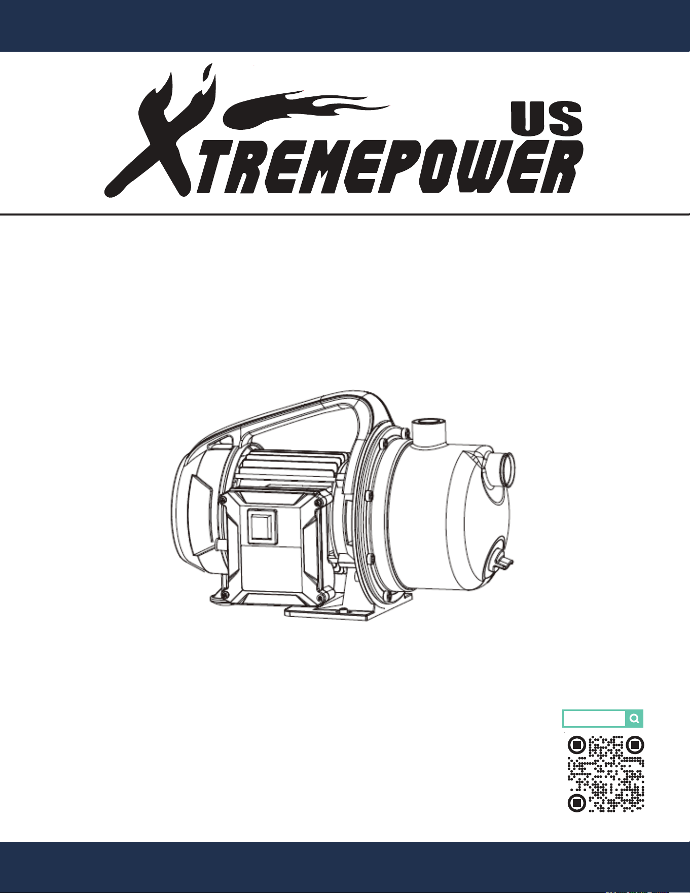
SKU: 71044
GARDEN IRRIGATION SHALLOW WELL PUMP
1320 GPH 1.6 HP
71044


1
TABLE OF CONTENTS
1
TABLE OF CONTENTS
IMPORTANT SAFETY INSTRUCTIONS
OVERVIEW (PRODUCT INFORMATION)
PRODUCT OVERVIEW
SPECIFICATIONS
INSTALLATION
PUMP PLACEMENT
PIPING
OPERATION
PRIMING
OPERATING
TROUBLESHOOTING
MAINTENANCE
ADDITIONAL TIPS
DISPOSAL
ENVIRONMENTALLY RESPONSIBLE DISPOSAL
REPLACEMENT PARTS
9
12
13
13
14
Disclainmer
Legends and Symbols
DISCLAIMER 15
1
15
2
2
4
4
6
5
6
7
8
8
8
11
MOTOR PROTECTION
WEARABLE PARTS
CLEANING
11
11
11
STORAGE
11
PARTS DIAGRAM
14
Customer Service and Technical Support
15
PRODUCT INTRODUCTION
4
1
IMPORTANT SAFETY INSTRUCTIONS
2
For safety reasons, children should not be allowed to use this product.
Packing materials and plastic bags are not toys. Keep them away from children to prevent the risk of
suffocation.
Failure to comply with all instructions and warnings may lead to severe bodily injury
or even death. This pump must be installed and serviced exclusively by a qualified service
professional. Prior to using this pump, installers, operators, and owners must carefully review these
warnings and all instructions provided in the owner's manual. It is essential to leave these warnings
and the owner's manual with the owner for their reference and safety.
ATTENTION INSTALLER: This manual contains vital information regarding the installation, operation,
and safe use of this pump. It is essential to provide this manual to the end user of the product. Failure
to read and follow all instructions could lead to severe injuries.
USE OF NON-XTREMEPOWERUS REPLACEMENT PARTS VOIDS WARRANTY
DANGER: Ignoring these hazards can result in death, severe personal injury, or
significant property damage.
WARNING: Indicates potential hazards that can result in severe personal injury,
death, or significant property damage. Ignoring these warnings presents a real
danger.
CAUTION: Indicates potential hazards that can result in minor or moderate
personal injury, property damage, or actions that are unpredictable and unsafe.
Ignoring these cautions presents a potential hazard.
NOTICE: This label indicates important special instructions that are not directly
related to hazards.
This guide provides instructions for installing and using the pump. If you have any questions about the
equipment, please contact XtremepowerUS.
This guide contains important information about safely installing and operating this product. After
installation, make sure to share this information with the owner/operator or leave it with them for their
reference.
Legends and Symbols
When you come across the safety-alert symbol on your equipment or in this manual, pay attention to
the following signal words and remain vigilant about the potential for personal injury.
IMPORTANT SAFETY INSTRUCTIONS
DANGER
WARNING
WARNING
CAUTION
NOTE
DANGER

1
IMPORTANT SAFETY INSTRUCTIONS
3
WARNING
Electrical Safet:
• Wiring and electrical connections must be performed by a licensed electrician.
• Install the pump and electrical components above the water level for indoor use to reduce the risk
of electrical shock.
• Keep the motor area as dry as possible and avoid washing or immersing the motor.
• Connect the pump directly to a grounded GFCI outlet.
• To reduce the risk of electrical shock, ensure the motor is grounded, and the terminal cover is
securely bolted in place.
• Do not ground the pump to a gas line.
• Always disconnect power before servicing.
• Please note that this pump is not suitable for use in swimming pool areas.
Grounding:
• The pump must be grounded during operation to protect against electrical shock. It comes with an
electric cord featuring an equipment-grounding conductor and grounding plug.
WARNING
NOTE
Usage Guidelines:
• This water pump is not equipped with water-sprinkling protection and should only be used in a dry
environment. Do not use it in rainy or humid conditions.
• Do not use this water pump with flammable or harmful liquids.
• Avoid idle operation of the water pump.
• This water pump is designed for clean water applications, including garden irrigation, household
water supply, and garden or farmland sprinkling.
• Do not expose the pump to impurities like sand, stones, or sticky substances, as these may
damage the pump. Never use this pump for conveying drinking water.
• To prevent dry suction and potential pump damage, the machine includes an automatic shutdown
feature in case of insufficient water supply.
Safety:
• This electrical garden pump with press control is suitable for outdoor use, such as in the garden.
• This pump is exclusively designed for residential use and is not intended for professional or
commercial purposes.
WARNING
1
OVERVIEW (PRODUCT INFORMATION)
4
OVERVIEW (PRODUCT INFORMATION)
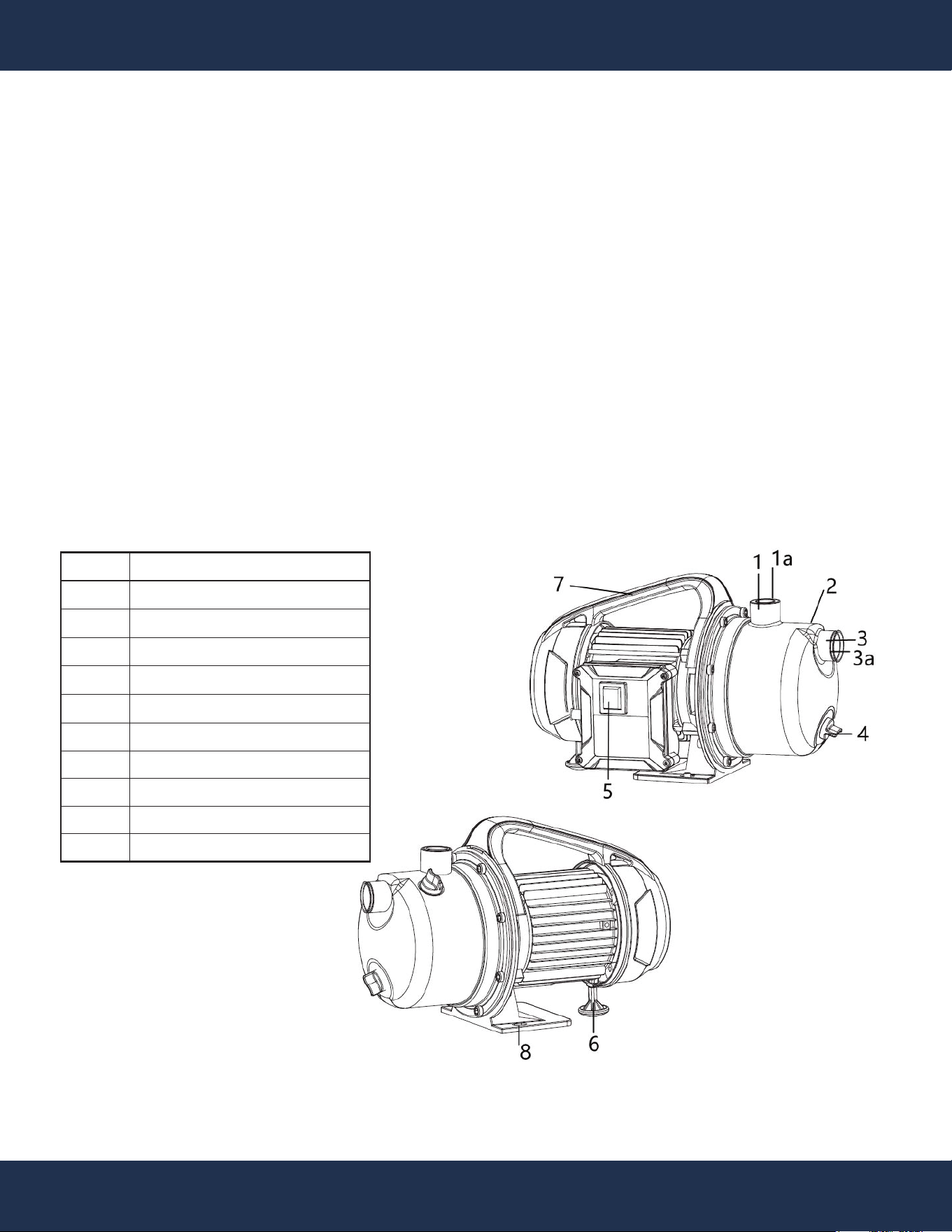
PRODUCT OVERVIEW
Item
1
1 a
2
3
3 a
4
5
6
7
8
Description
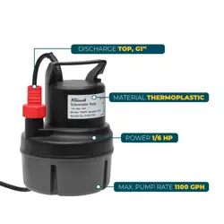
Discharge 1 INCH NPT
Sealing Cap
Prime Cap Screw
Suction Inlet 1 INCH NPT
Sealing Cap
Drain Cap Screw
Power Switch
Supporting Foot
Carrying Handle
Fixing Points
PRODUCT INTRODUCTION
This versatile shallow well jet pump is ideal for a range of freshwater supply needs, including rural
homes, cabins, farms, and more. It's designed for installations where the vertical distance from the
pump to the water level doesn't exceed 26 FT. The pump features a 1 INCH NPT discharge and 1
INCH NPT suction, and it should not be used with saltwater, brine, or liquids containing caustic
chemicals or foreign materials.
Common Applications:
• Watering and irrigating green areas, vegetable beds, and gardens.
• Operating lawn sprinklers.
• Utilizing a pre-filter (not included) to draw water from ponds, streams, rainwater barrels, rainwater
cisterns, and wells.

1
OVERVIEW (PRODUCT INFORMATION)
5
SPECIFICATIONS
Model
Voltage
Power
Amps
Max. Lift
Max. Suction Height
Max. Flow
Inlet Size
Discharge Size
Max. Water Temperature
Water Proof Class
71044
120 V / 60HZ
1.6 HP
10 A
157 FT
26 FT
1268 GPH
1 INCH NPT
1 INCH NPT
95 °F
IPX 4
Max.
Head FT
157 FT
Discharge
NPT (INCH)
1 INCH NPT
GPH of Water @ Total FT Of Head
50 FT
1020
0 FT
1268
100 FT
600
150 FT
154
INTENDED USE AND SUITABILITY
This shallow well jet pump is designed for a variety of freshwater supply needs, making it well-suited for
rural homes, cabins, farms, and more. It can be installed in locations where the vertical distance from
the pump to the water level does not exceed 26 FT. The pump features a 1 INCH NPT discharge and 1
INCH NPT suction and should not be used with saltwater, brine, or liquids containing caustic chemicals
or foreign materials.
Examples of Applications:
• Watering and irrigating green areas, vegetable beds, and gardens.
• Operating lawn sprinkler systems.
• When equipped with a pre-filter (not included), it can draw water from ponds, streams, rainwater
barrels, rainwater cisterns, and wells.
INSTALLATION
6
INSTALLATION
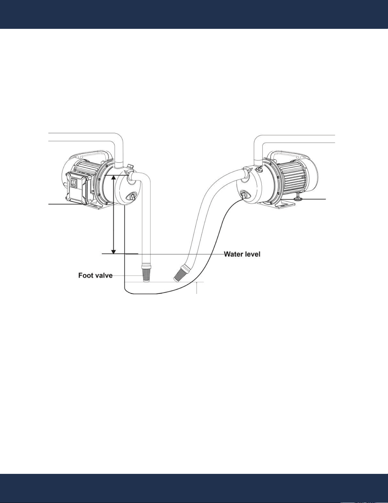
• Install in a clean, dry, well-ventilated area.
• Position horizontally on a solid foundation.
• Keep close to water source (Max 26 FT).
• Use a foot valve to maintain priming; keep it submerged 5 FT above well bottom.
PUMP PLACEMENT
Max 26 FT
Min 5 FT
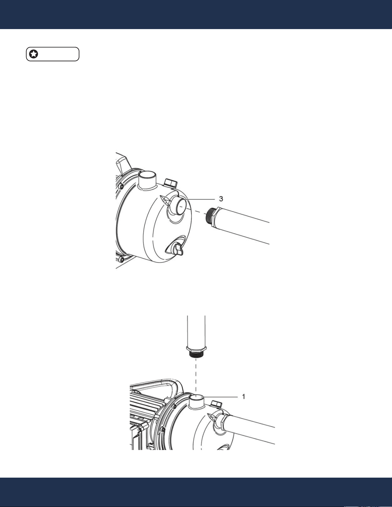
Use new, clean piping that matches flow rates, pressure, and water quality.
• Remove and store sealing cap (3a) from suction inlet (3).
• Connect hose adapters to suction inlet (3).
• Attach the suction line using the appropriate system.
• Position the line from the water source to the garden pump.
INSTALLATION
7
NOTE
Always use sealant tape on threaded connections.
• For the discharge line, utilize either a 1 INCH NPT standard garden hose (sold separately) or
employ hose adapters to connect a garden hose.
• Begin by removing the sealing cap (Part # 1a) from the discharge outlet (1).
PIPING
OPERATION
8
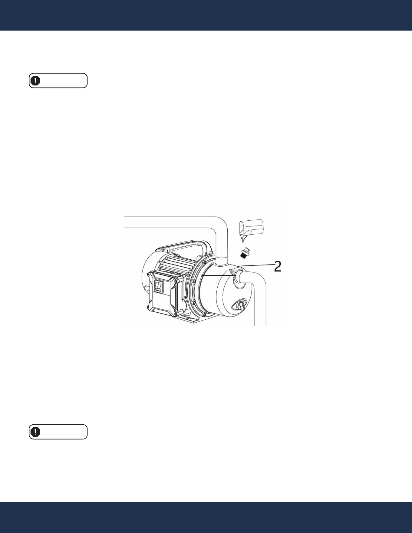
PRIMING
OPERATION
• Confirm the suction line is connected to prevent water leakage.
• If a service line is in place, open the discharge valve; if not, open a tap to release air from the
suction line.
• Fill the pump through the prime plug (2) until water flows out.
• Tilt the pump slightly to remove air pockets.
• Re-install and hand-tighten the priming plug.
Ensure the pump is filled with water before use. Running the pump dry can damage the shaft seal and
void the warranty.
WARNING
OPERATING
Plug the power cord into a GFCI-protected electrical outlet and switch the power to the "On" position.
• Start the pump and run for 1.5 - 2 minutes; it should pump continuously.
• If not, repeat the PRIMING steps.
• For initial startup, repeat priming as needed to remove air, typically 3-6 cycles.
• If no water after 6 cycles, turn off and check for leaks.
The pump runs continuously once turned on. Keep it under constant observation to prevent damage
from dry running, as it lacks a dry-running cutoff. The pump has overheating protection and will shut
off if it becomes too warm.
WARNING

TROUBLE SHOOTING
9
ISSUE
The electric motor
runs, but the pump
doesn't draw water.
The electric motor
isn't running.
Insufficient water flow.
CASE
Once the pump starts,
it doesn't fill with water.
The suction hose isn't
tightly sealed.
The filter screen on the
non-return valve at the
suction inlet is clogged.
Air can't escape from
the pressure hose due
to a closed water
outlet.
The waiting time
doesn't meet
regulations.
Suction head is too
high (over 26 FT).
The non-return valve
fails to draw water.
No power supply.
The fan's rotation is
obstructed by the
ventilator hood.
The fan is blocked.
Suction head exceeds
maximum (over 26 FT).
The non-return valve's
filter screen is clogged.
The suction water level
dropped too low.
Impurities have
diminished the pump's
effective capacity.
CORRECTIVE ACTION
Prime the pump with water.
Ensure proper sealing of pump components
like the suction nose joint, pressure hose
joint, clamping ring, suction hose, and
Teflon or hemp cord sealing strip. A
well-sealed pump is essential for operation.
Clean the non-return valve at the suction
inlet and the filter screen.
Once the pump begins suction, open the
water outlet (e.g., tap or sprinkling nozzle).
Fill the entire suction hose with water, or
recheck it at least 7 minutes after the pump
starts.
Reduce the suction head.
Verify the water level in the well or water
pool. If possible, lengthen the suction hose.
Verify the power supply.
Disconnect the power plug, remove the
ventilator hood using a screwdriver, reinstall
it while gently rotating the vane, and check
for free rotation.
Disconnect the power plug, manipulate the
shaft through the ventilator hood using a
screwdriver. If the shaft is blocked, send it to
a service center for inspection.
Verify the suction head.
Clear the filter screen.
Submerge the non-return valve in deep
water.
Clean the pump's shell, suction hose, and
outlet pressure hose using pressurized
water.

TROUBLE SHOOTING
10
ISSUE
The heat-sensitive
switch can't turn off the
pump.
The pump's switch
remains either OFF or
ON.
Frequent switching of
the pump's ON/OFF
switch (when used in a
household water supply
system).
CASE
Electric motor
overload due to
friction from impurities
entering the motor.
Absence of a
non-return valve on
the suction hose.
Rubber envelope in
the pressure tank is
damaged.
The container lacks
compressed air.
CORRECTIVE ACTION
Clean the pump's shell with pressurized
water.
Verify the presence of a valve on the suction
hose.
Replace either the rubber envelope or the
container.
Install an appropriate valve and connect it to
a compressed air supply at 1.8 BAR (26.1
PSI), then fill the container with air.
9
MAINTENANCE
11
MOTOR PROTECTION
MAINTENANCE
• Prevent water from entering the motor.
• Avoid spraying or cleaning the product with running water to prevent electric shock and damage.
WARNING
WEARABLE PARTS
NOTE
• The seals, pre-filter, flow sensor wheel, and non-return valve are subject to natural wear.
• Some wearable parts may not be included in the package.
CLEANING
• Periodically clean the product with a damp cloth and mild soap.
• Avoid using cleaning products or solvents as they can harm plastic components.
WARNING
STORAGE
• Store the pump in a dry place to prevent flooding and excess moisture.
WARNING
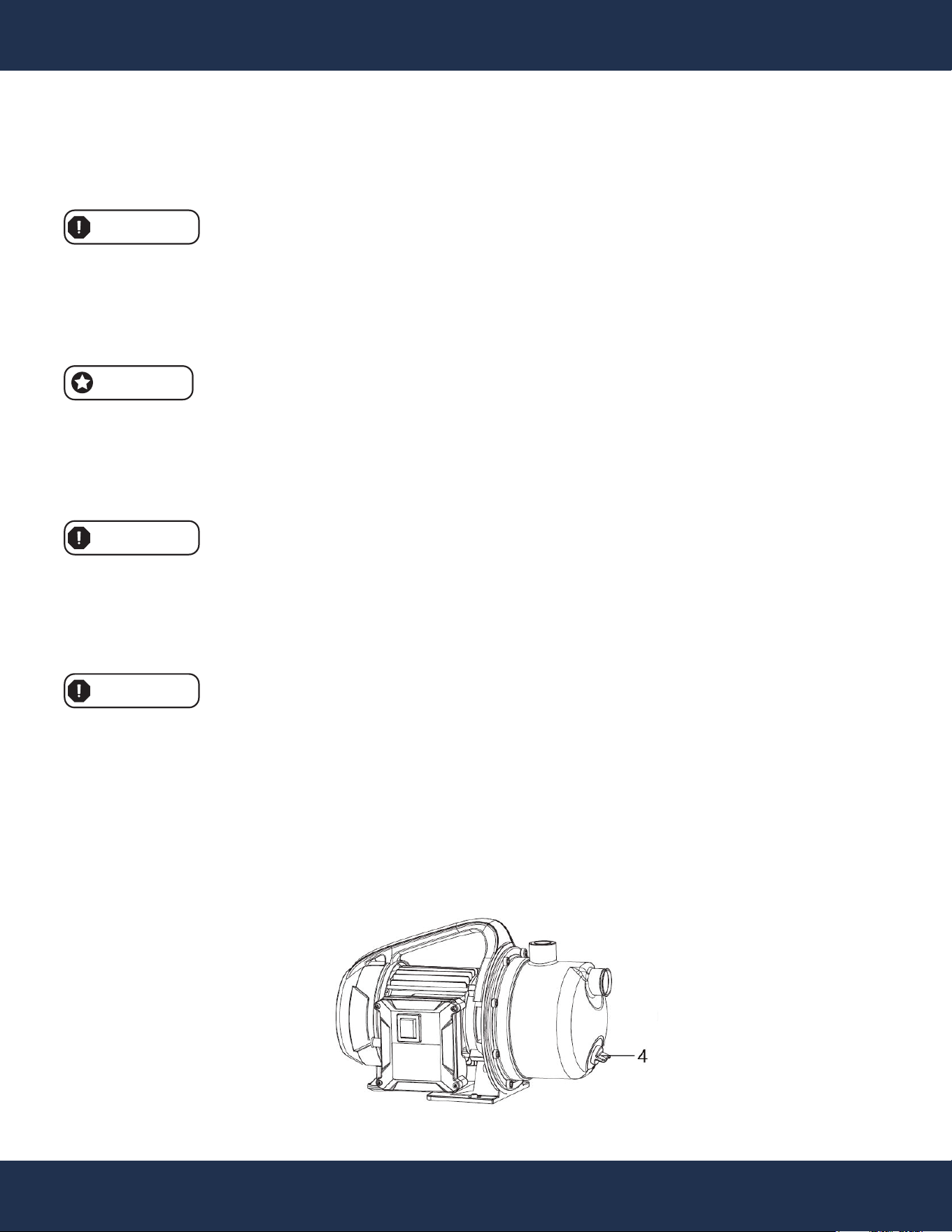
Winter Draining:
• Disconnect suction and discharge lines.
• Remove the water drain cap screw (4) from the pump, allowing time for drainage before
reinstallation.
• Drain piping below the frost line or store it indoors.
• Store the pump indoors.
• Always disconnect the power plug before any equipment work.

ADDITIONAL TIPS
• Avoid exposing the pump to rain, humidity, dirt, or freezing conditions.
• Prevent freezing, idling, or blockage by impurities.
• In case of power cable damage, seek professional replacement, as short-circuit damage is not
covered by the warranty.
• For pump issues, consult an authorized maintenance center.
• Do not use solvents like petrol, alcohol, or ammonia water, as they can damage plastic parts.
WARNING
MAINTENANCE
12

11
DISPOSAL
13
DISPOSAL
NOTE
• When replacing your appliance, don't discard it with household waste. Dispose of it in an
environmentally safe manner. Electrical waste requires special handling and recycling, not
standard disposal. Use recycling facilities where available, or consult your Local Authority or
retailer for guidance.
• For power tools and packaging, prioritize environmentally-friendly recycling. Never dispose of
power tools as regular household waste. Utilize designated collection points for recycling.
Contact your local authority for recycling information.
ENVIRONMENTALLY RESPONSIBLE DISPOSAL
REPLACEMENT PARTS
14
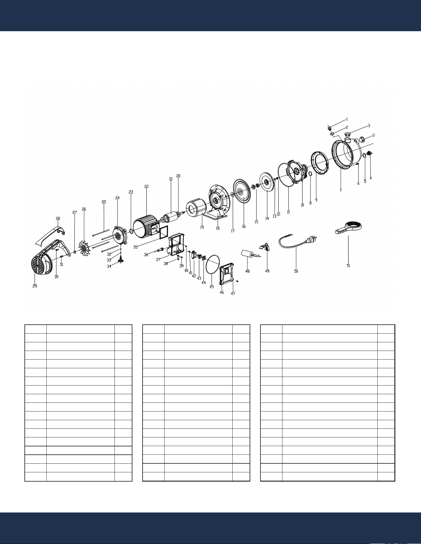
REPLACEMENT PARTS
PARTS DIAGRAM
Item
1
2
3
4
5
6
7
8
9
10
11
12
13
14
15
16
17
Description
Screw Cover
O-Ring
Plastic Cover
Screw Cover
O-Ring
Screw
Pump Head-SS
O-Ring
Plastic Cover Ring
Diffuser
O-Ring
Screw Nut
Gasket
Impeller
Mechanical Seal
SS-Flange
Swing Ring
Qty
1
1
2
1
1
8
1
1
1
1
1
1
1
1
1
1
1
Item
18
19
20
21
22
23
24
25
26
27
28
29
30
31
32
33
34
Description
Bracket
Stator
Bearing
Rotor
Main Body
Wave Gasket
Motor Back Cover
Body Screw
Fan
Clamp Spring
Handle
Fan Cover
Screw
Screw
Seal
Spring Seal
Support Foot
Qty
1
1
2
1
1
1
1
4
1
1
1
1
2
2
1
1
1
Item
35
36
37
38
39
40
41
42
43
44
45
46
47
48
49
50
51
Description
Rubber Seal
Cable Bracket
Switch Box-Basic
Cable Buckle
Screw
Screw
Screw& Gasket
Switch Buckle
Switch
Switch-Cover
O-Ring
Switch Box-Cover
Screw
Capacitance
Capacitance Buckle
Cable
Wrench
Qty
1
1
1
1
2
4
2
1
1
1
1
1
4
1
1
1
1

DISCLAIMER
PLEASE READ THE FOLLOWING CAREFULLY
The manufacturer and/or distributor have provided the parts list and assembly diagram in this manual
for reference purposes only. They do not make any representation or warranty to the buyer that they
are qualified to make repairs to the product or replace any parts of the product. In fact, the
manufacturer and/or distributor expressly state that all repairs and parts replacements should be
undertaken by certified and licensed technicians, and not by the buyer.
The buyer assumes all risk and liability arising from their repairs to the original product or replacement
parts or arising from their installation of replacement parts. It is strongly advised that qualified
professionals handle any repairs or replacements to ensure safety and proper functioning of the
product. Improper installation and operation may result in injury, property damage, or voiding of
warranty. The manufacturer and/or distributor shall not be held responsible for any accidents,
damages, or malfunctions resulting from the buyer's installation and operation of the product. It is
essential to follow all safety guidelines and recommendations provided in this manual and to seek
professional assistance if unsure about the installation or operation procedures.
DISCLAIMER
15
CUSTOMER SERVICE
If you have any questions about ordering our pool pumps and replacement parts or pool products,
please feel free to contact us using the following contact information:
Customer Service and Technical Support
Phone: (909) 628-0880
Email: [email protected]
Hours of Operation: Monday – Friday, 9AM – 4PM (CST)