INSTALLATION INSTRUCTIONS
Vented Tumble Dryer
EN
TD86
T5VXLW.U
T5VXLG.U
T5VXLT.U
T7VXLW.U
Carefully read the instructions for use before using the dryer.

3Introduction ................................................
4Important safety instructions ...................
5
Electrical hazard warning during
servicing .....................................................
6Installation and connection ......................
7Technical data .............................................
7Selecting the room .......................................
7Dryer placement ..........................................
9Adjusting the dryer feet ...............................
10Installation under the counter ......................
11Stacking on top of a washing machine ........
14Built-in ..........................................................
16Changing the door opening direction ..........
17Air exhaust ...................................................
21Electrical installation ....................................
Contents
Dear Customer,
Read these instructions carefully and completely before you install the machine. The installation
should be carried out by a qualified person who is familiar with all local codes and ordinances for
electrical and plumbing connections. See also the general Safety Instructions in the Use & Care
Guide.
Cosmetic damage must be reported to the ASKO dealer within five days from the date of purchase.
As soon as you unpack the machine, thoroughly check it for cosmetic damage.
The following symbols are used throughout the manual and they have the following meanings:
INFORMATION!
Information, advice, tip, or recommendation
WARNING!
Warning – general danger
ELECTRIC SHOCK!
Warning – danger of electric shock
HOT SURFACE!
Warning – danger of hot surface
DANGER OF FIRE!
Warning – Risk of Fire
Original instructions
SAVE THESE INSTRUCTIONS FOR FUTURE REFERENCE!
3
Introduction
SAVE THESE INSTRUCTIONS FOR FUTURE
REFERENCE!
WARNING!
To reduce the risk of fire, electric shock, or injury to persons
when using your appliance, follow basic precautions,
including the following:
WARNING!
Clothes dryer installation must be performed by a qualified
installer.
WARNING!
Install the clothes dryer according to the manufacturer's
instructions and local codes.
WARNING!
For proper ventilation, the machine should not be installed
behind a door.
The tumble dryer’s toe kick ventilation must not be blocked
by a rug or the like.
DANGER OF FIRE!
Do not install a clothes dryer with flexible plastic venting
materials. If flexible metal (foil type) duct is installed, it must
be of a specific type identified by the applience
manufacturer that is UL approved for use with clothes dryers.
Flexible venting materials are known to collapse, be easily
crushed, and trap lint. These conditions will obstruct clothes
dryer airflow and increase the risk of fire.
4
Important safety instructions
DANGER OF FIRE!
Do not install a booster fan in the exhaust duct.
Note: The booster fan warning does not apply to clothes
dryers intended to be installed in a multiple clothes dryer
system, with an engineered exhaust duct system that is
installed per the clothes dryer manufacturer’s guidelines.
Electrical hazard warning during servicing
ELECTRIC SHOCK!
Certain internal parts are intentionally not grounded and
may present a risk of electric shock only during
servicing. Service Personnel – Do not contact the
following parts while the appliance is energized: motor,
pump and control unit.
5
Important safety instructions
DANGER OF FIRE!
To reduce the risk of fire, do not dry articles containing foam rubber or similarly textured rubber-like
materials.
WARNING!
Install the clothes dryer according to the manufacturer’s instructions and local regulations.
WARNING!
Clothes dryer installation must be performed by a qualified installer.
WARNING!
To reduce the risk of severe injury or death, follow all installation instructions.
WARNING!
The appliance shall not be exhausted into a chimney, a wall, a ceiling, an attic, a crawl space,
or a concealed space of a building.
Only rigid or flexible metal duct shall be used for exhausting.
• Canada: Only foil-type flexible ducts that are specifically identified for use with this appliance
by the manufacturer shall be used.
• United States: Only foil-type flexible ducts that are specifically identified for use with this
appliance by the manufacturer and comply with UL 2158A shall be used.
• Canada: The exhaust duct must have a diameter of 4 inches (102 mm).
• United States: The exhaust duct diameter must comply with the manufacturer’s specifications
and applicable local building codes. These requirements may vary by location and must be
followed to ensure compliance and safety.
Maximum duct length shall be 8 feet (2.4 m) and maximum number of bends shall be 4.
The total length of flexible metal duct shall not exceed 8 feet (2.4 m).
The duct shall not be assembled with screws or other fastening means that extend into the duct
and catch lint.
WARNING!
Save these instructions.
6
Installation and connection
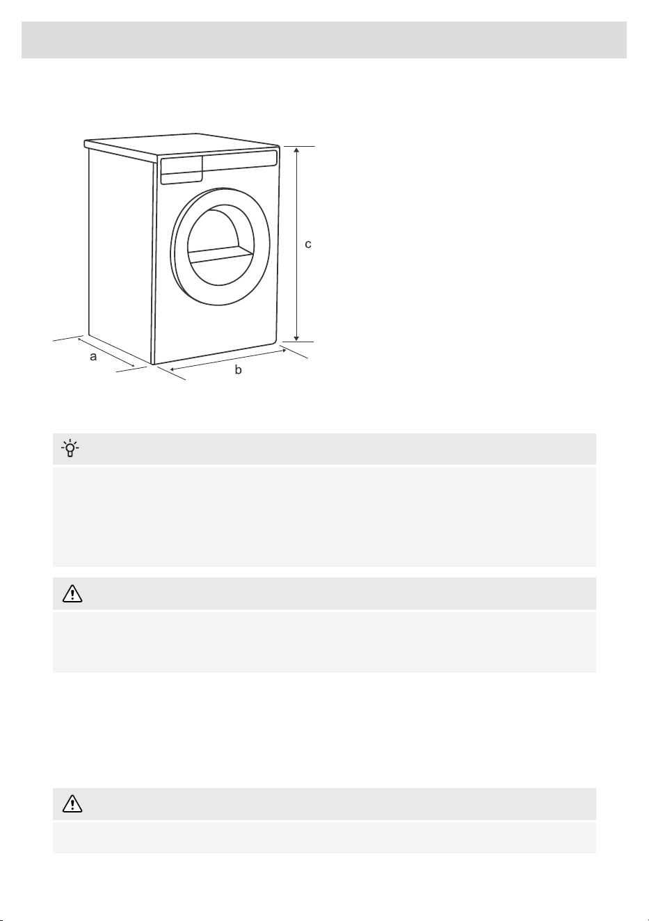
Technical data
a - The dryer depth 29 1/4" (743 mm).
b - The dryer width is 23 7/16" (595 mm).
c - The dryer height is 33 7/16" (850 mm).
Selecting the room
INFORMATION!
Do not place the dryer in a room where temperature can drop below 32 °F (0 °C), as the machine
may not operate correctly at such low temperatures or may freeze, which can result in damage
to the machine.
Install the dryer in a room with adequate ventilation and a temperature between 50 °F (10 °C)
and 77 °F (25 °C).
WARNING!
Do not place the dryer behind lockable or sliding doors, or doors with a hinge on the opposite
side of the dryer door hinge. Install the dryer in such way that the door can always be freely
opened.
Dryer placement
The dryer can be either free standing or installed on top of a washing machine.
The dryer emits heat. Therefore, do not place it in a very small room, as the drying process may be
longer due to limited amount of ambient air.
WARNING!
Never block the air exhaust (ventilation opening).
7
Installation and connection
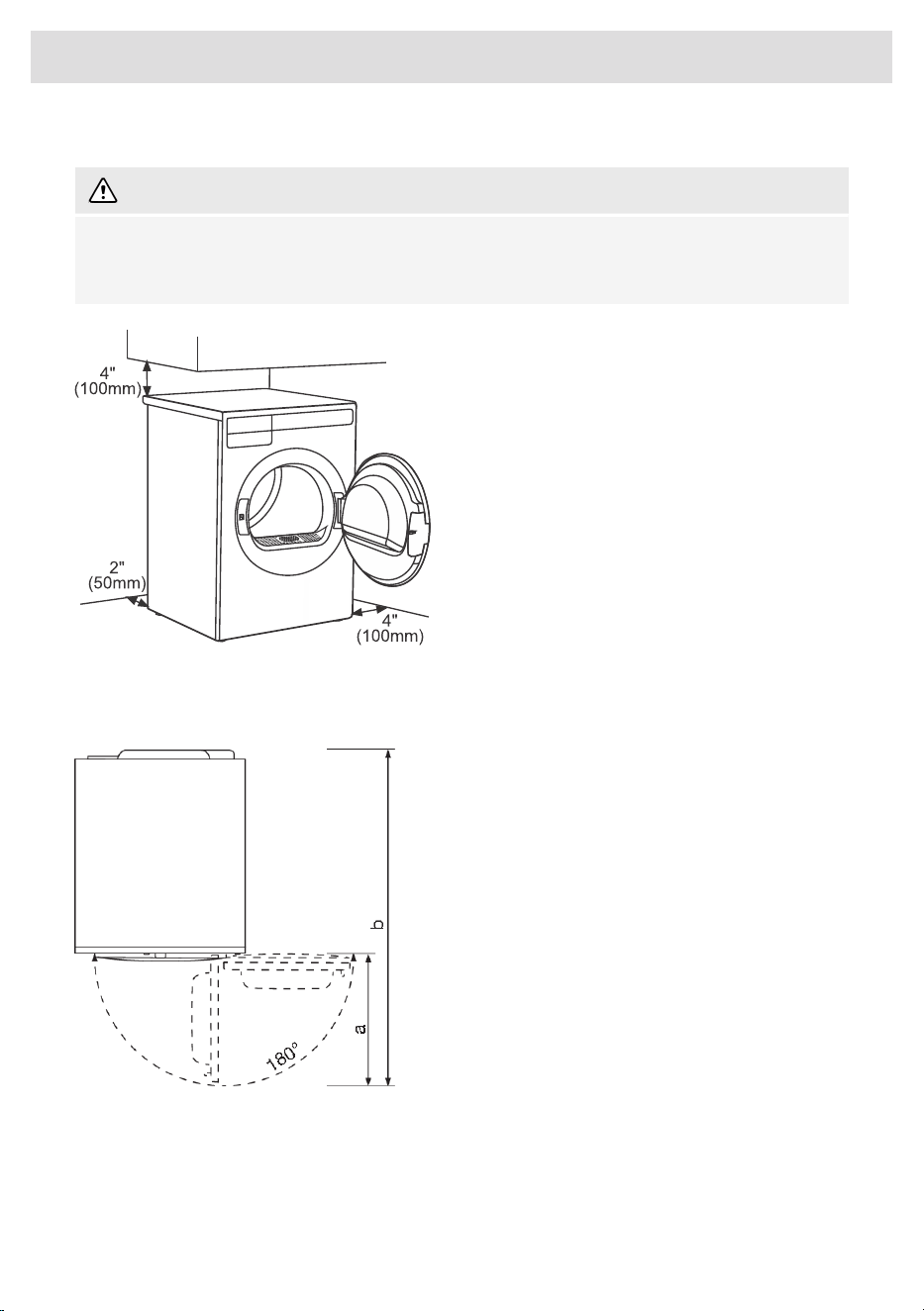
Clearance around the dryer for optimum operation
WARNING!
The dryer must not be in contact with a wall or adjacent furniture. For optimal dryer performance,
we recommend maintaining the clearances from the walls as shown in the figure. Failure to
observe the required minimum clearance may cause the dryer to overheat.
For safety reasons, maintain a minimum
clearance of 1" (25 mm) between the back of
the appliance and the wall, and at least 1 5/8"
(40 mm) between the top of the appliance and
any overhead structure.
For installing the dryer into a cabinet, refer to
the special installation requirements in section
Built-in.
Opening the dryer door (top view)
The dryer door width (a) is 19 13/16" (503 mm).
The dryer depth with door open (b) is 48 1/2"
(1231 mm).
The dryer door can be opened up to the angle
of 180°.
8
Installation and connection
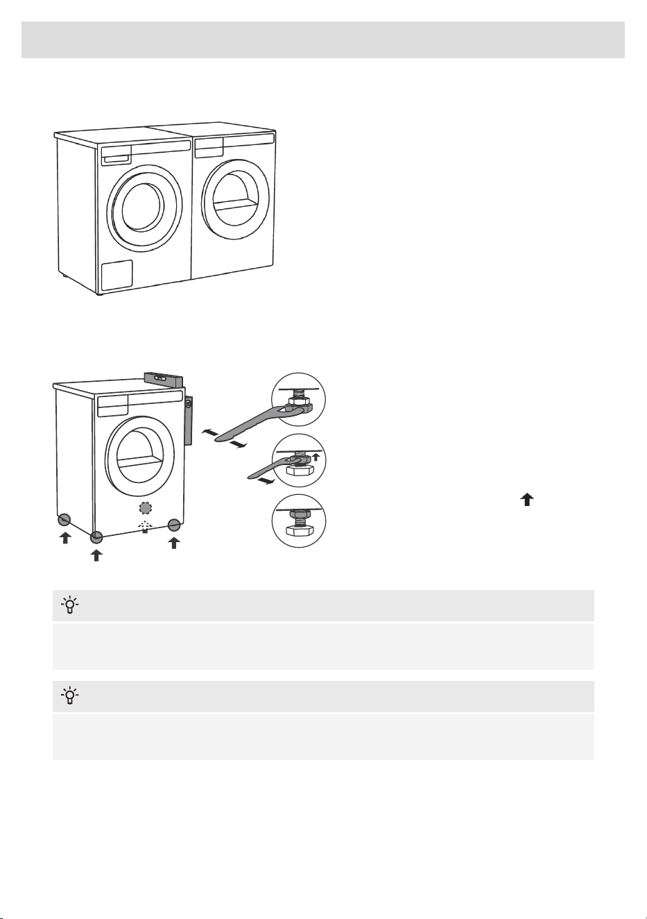
Freestanding appliance
The dryer may be placed adjacent to a
washing machine.
If the friction between the dryer feet and the
floor is not sufficient, the dryer may move
during operation.
To prevent sliding, use anti-slip mat or attach
the supplied suction feet to both front legs.
Adjusting the dryer feet
Place the dryer so that it is stable.
Use a spirit level to level the dryer both
front-to-back and side-to-side by rotating the
adjustable feet with a No. 7/8" (22) wrench
(max. 9/16" (15 mm)).
Then, firmly tighten the jam nuts (counter nuts)
by rotating them towards the appliance bottom
using a No. 11/16'' (17) wrench .
INFORMATION!
Incorrect leveling of the dryer with the adjustable legs may cause vibration, appliance sliding
across the floor, and loud operation. Incorrect leveling of the dryer is not covered by the warranty.
INFORMATION!
Sometimes, unusual or louder noises may occur during appliance operation; these are mostly
the result of improper installation.
9
Installation and connection
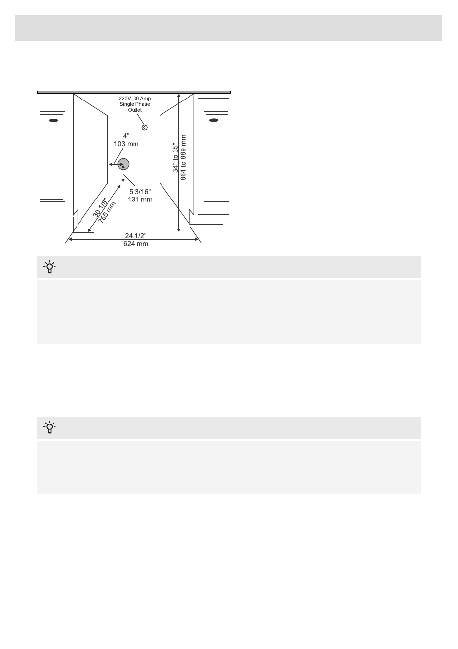
Installation under the counter
ASKO dryers can be installed under a counter
or a countertop that is at least 34" (864 mm)
high, measured from the floor to the underside
of the countertop. There must be a clearance
of at least 1/2" (12 mm) on all sides of the
appliance. There must be a minimum
clearance of 1" (25 mm) between the rear edge
of the appliance's top panel and the wall
behind it. The width of the opening or niche
where the appliance is to be installed must be
at least 24 1/2" (624 mm), measured between
the side walls of the niche.
INFORMATION!
The height adjustment for the dryer is between 33 1/2" (850 mm) to 34 1/2" (876 mm). Do not
raise the appliance higher than 34 1/2" (876 mm).
It is very important to avoid a buildup of heat.
The warm air which is expelled from the rear of the dryer must be able to dissipate.
Warm air which cannot dissipate could cause a fault.
A buildup of heat can be avoided by:
• Creating a gap for the dryer in the kitchen cabinet toe space.
• Creating ventilation gaps in the surroundings.
When built in, drying times may be longer.
INFORMATION!
The dryer should not be installed next to a refrigeration appliance. The warm air expelled from
the back of the dryer can increase the temperature around the refrigeration appliance’s heat
exchanger, causing the compressor to run continuously. If it is not possible to install the dryer
elsewhere, the refrigeration appliance must be properly sealed off from the dryer.
10
Installation and connection
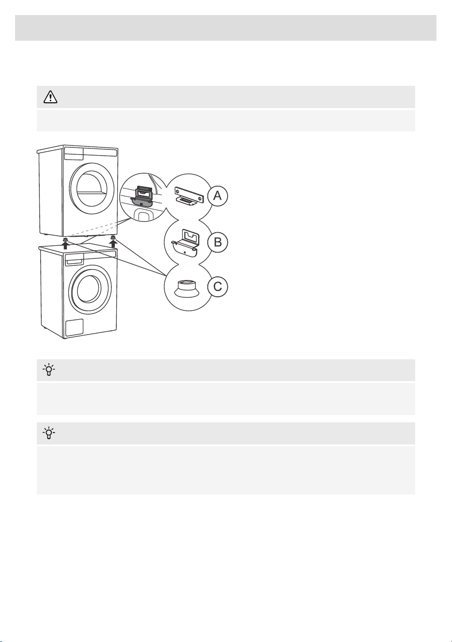
Stacking on top of a washing machine
WARNING!
At least two people are required to install the tumble dryer on top of a washing machine.
To stack the dryer on top of a washing
machine, use the front feet attachments
(suction feet (C)) and the tipping guard (A+B)
supplied inside the dryer drum.
If the washing machine and dryer are not the
same dimensions, you can purchase a
connecting plate designed for the WM86–TD76
combination from your dealer.
INFORMATION!
The tipping guard (B) is designed for ASKO washing machines and cannot be installed on washing
machines from other brands
INFORMATION!
The washing machine on which you wish to install the dryer must be able to bear the weight of
the dryer (see washing machine’s rating plate or technical information).
All ASKO washing machines can bear the weight of the ASKO dryer.
11
Installation and connection
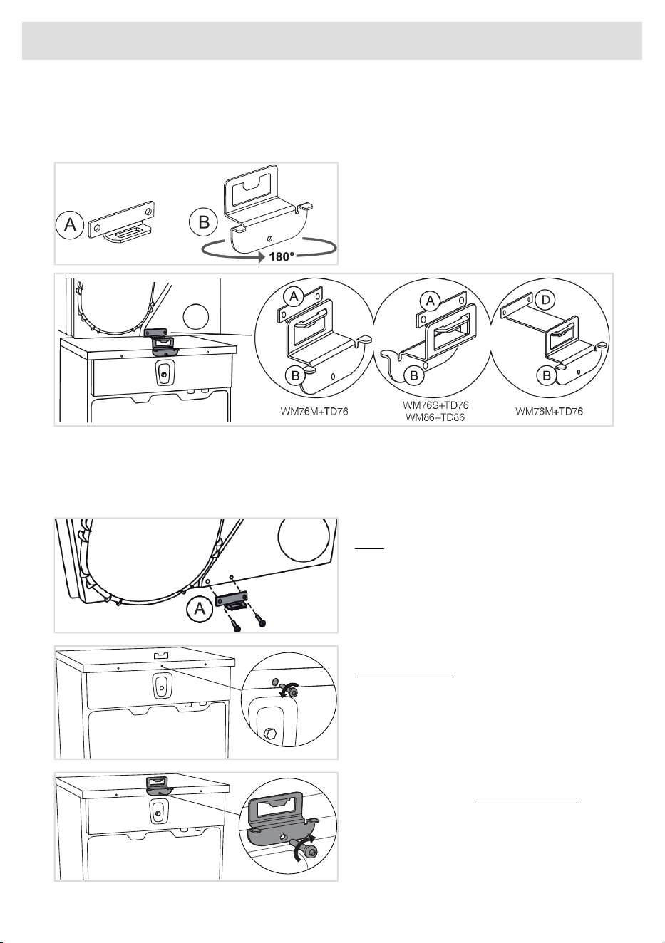
How to stack a dryer onto the washing machine (ASKO)
A cardboard box inside the dryer drum contains the tipping guards (A, B), suction feet (C), and
screws.
1 The tipping guard consists of two metal
parts (A + B).
Part (B) can be rotated 180°. Turn it according
to the depth of the washing machine and dryer.
Select the correct combination based on the type of washing machine and dryer, as indicated
on the rating plate located on the inside of each appliance’s door.
If your dryer is shallower than the washing machine, you can purchase a suitable longer guard (D)
from your dealer (ART. No.: 924231 OVERTURNING PROTEC.TD-76/WM-86).
2 Attach part (A) to the rear bottom of the
dryer using the two screws included in the
package.
3 Undo the screw on the back side of the
washing machine.
4 Use the screw to attach the tipping guard
(B) to the back of the washing machine.
Turn the part (B) according to the depth of
your dryer and washing machine (see point
1).
12
Installation and connection
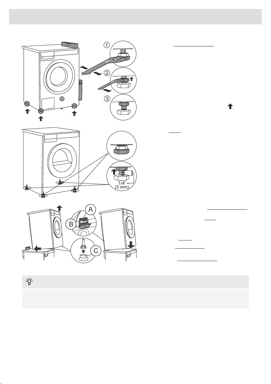
5 Level the washing machine so that it is
stable.
1. Level the washing machine by rotating the
adjustable feet using a No. 32 (1.26")
wrench. The feet allow levelling by +/- 3/8"
(1 cm).
2. After adjusting the height of the feet, firmly
tighten the jam nuts using a spanner No
17 (11/16"), by turning them towards the
bottom of the washing machine .
3. Tighten the jam nuts.
6 Set the dryer feet:
1. Tighten the front two feet all the way in.
2. Loosen the rear feet by 3.5 turns or 1/4" (5
mm); then tighten the jam nuts toward the
bottom of the appliance
7 Place the dryer onto the washing machine.
1. Lift the front part of the dryer by 2"–4" (5–10
cm).
2. Attach the vacuum feet (C) onto the front
feet of the dryer.
3. Push the tumble dryer into the tipping
guard (part B into part A) and install it on
top of the washing machine.
INFORMATION!
Ensure that both parts of the tipping guard (A + B) are locked. The front of the washing machine
and dryer must be aligned!
13
Installation and connection
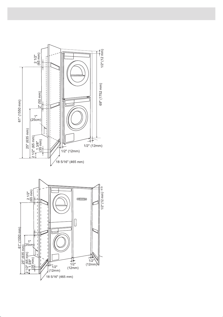
Built-in
Closet Install- Ventilation
Requirements
ASKO's front panel controls make it possible
to install the washers and dryers in a cabinet
or closet.
The distance between the left or right side of
the appliance and the surface of the side of
the cabinet or the surface of the wall of the
recess in which the appliance is installed must
be at least 1/2" (12 mm). The distance between
the back of the appliance (note the deepest
point of the appliance) and the surface of the
back of the cabinet or the wall of the recess
must be at least 1" (25 mm). See figure.
Ventilation Requirements of ASKO
laundry concept (when installing the
appliance in a closet)
Make sure there is space between the
appliance and the furniture element or wall,
and at least 1" (25) mm of space between the
back edge of the top panel of the appliance
and the furniture element or wall.
When the closet or cabinet is closed with a
door, we recommend using louvered doors to
ensure proper ventilation.
Otherwise, the door must have ventilation
gaps. See the figure for the dimensions of the
ventilation openings.
14
Installation and connection

INFORMATION!
Ensure the dryer door can be opened without hindrance after installation.
The cool air intake panel at the front of the dryer must not be blocked or covered. Doing so could
cause an error.
WARNING!
Failure to follow these instructions can negatively impact the appliance performance and may
also result in failure of the appliance.
15
Installation and connection
Changing the door opening direction
WARNING!
Before changing the door opening direction, the appliance must be disconnected from the power
supply! See chapter Important safety instructions.
WARNING!
Changing the door opening direction should be done by an installer, service provider, or similarly
qualified persons in order to avoid any hazards.
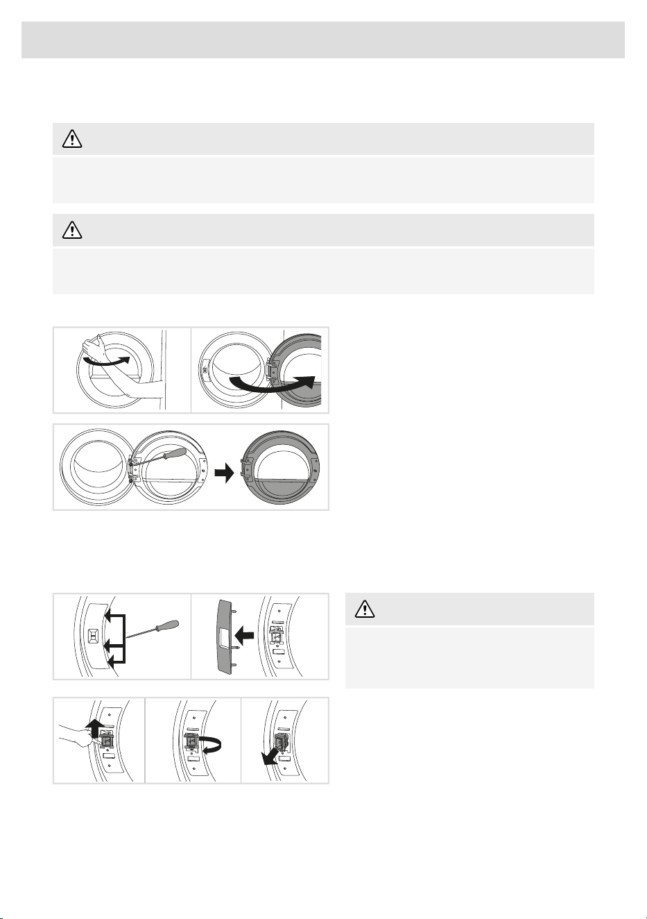
To change the direction of door opening, proceed as follows:
1 Open the door fully.
2 Undo the screws and remove the door.
3 Carefully remove the door lock cover with
a narrow, blunt object.
Release the latches on the door lock cover in
the indicated order.
WARNING!
When removing, make sure not to bend the
cover or its latches, as they may get
damaged.
4 Push the door lock up, slide it to the left and
remove it from the appliance in a rotating
motion.
16
Installation and connection
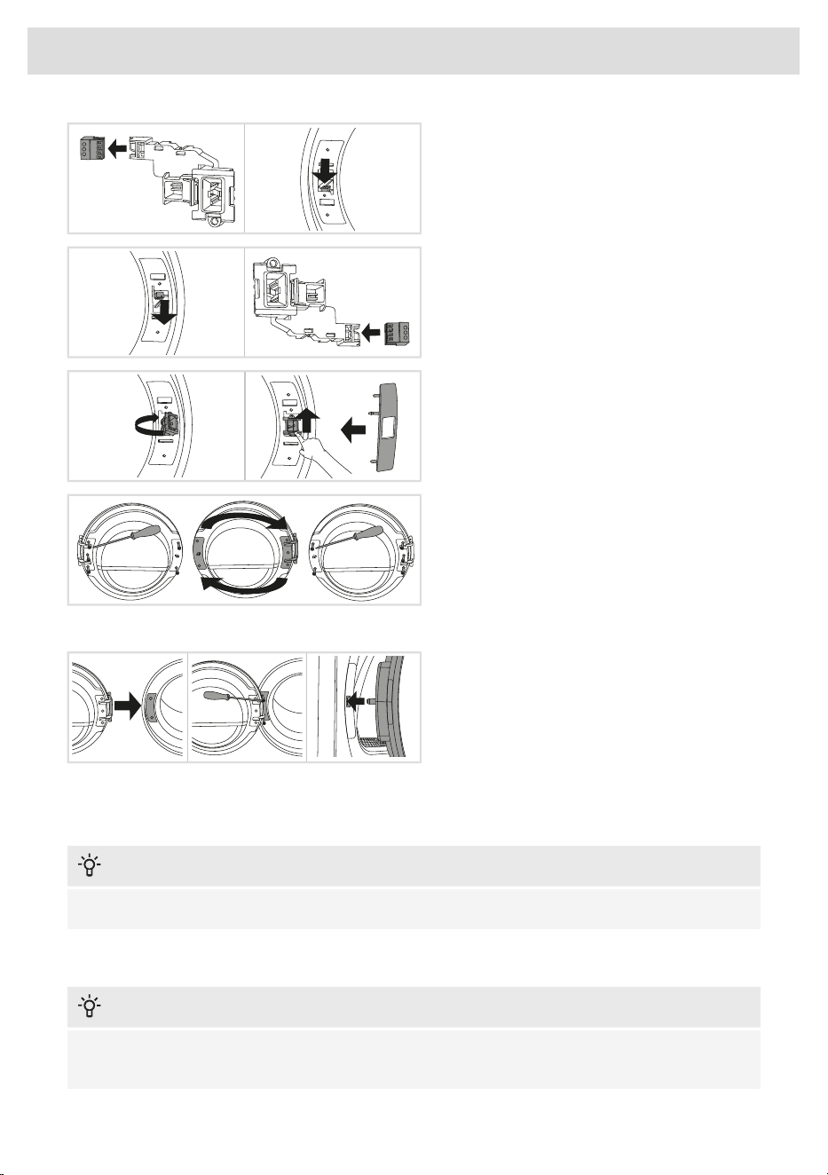
5 Remove the connector from the lock.
Insert the connector into the rib of the plastic
housing to prevent the appliance from rattling
when the connector is not plugged in.
6 On the opposite side where the door has
come off, remove the connector from the rib,
pull it out of the appliance and connect it to
the door lock.
7 Place the door lock in the appliance in the
reverse order of its removal from the appliance.
Remount the door lock cover.
8 Undo the door hinge assembly (left) and
the door latch assembly (right), switch their
positions, and replace the screws (door hinge
assembly to the right-hand side, door latch
assembly to the left-hand side).
Use a screwdriver to remove the plastic part
more easily.
9 Install the door on the front wall and screw
it in.
Install the door in a fully open position and
do not lift it while screwing. It is correctly
installed only if the door latch is aligned
with the center of the door catch or slightly
above it!
Air exhaust
INFORMATION!
The tumble dryer must only be operated when it is correctly fitted with exhaust duct.
Connecting the exhaust duct to the dryer
INFORMATION!
You will need to purchase a UL-CSA-approved 4" ridged metal exhaust duct. The dryer is delivered
with the stub pipe attached to the rear exhaust outlet.
17
Installation and connection
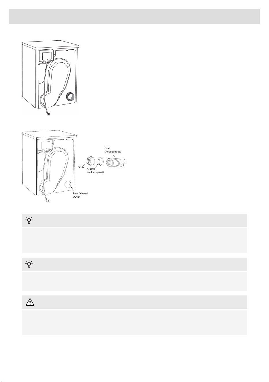
To connect the exhaust duct to the rear outlet,
follow the steps below:
• Using a flat-head screwdriver, remove the
exhaust outlet cover from the rear exhaust
outlet.
• Attach the stub pipe to the rear exhaust
outlet.
• Use the exhaust outlet cover you removed
to cover any unused openings or areas, if
applicable.
The duct must not be assembled with screws
or other fasteners that extend into the duct and
catch lint.
To connect the exhaust duct to the outlet,
follow the steps below:
• Push the duct onto the stub pipe and
secure it with a clamp.
• After you push the dryer into place, check
for kinks in the duct.
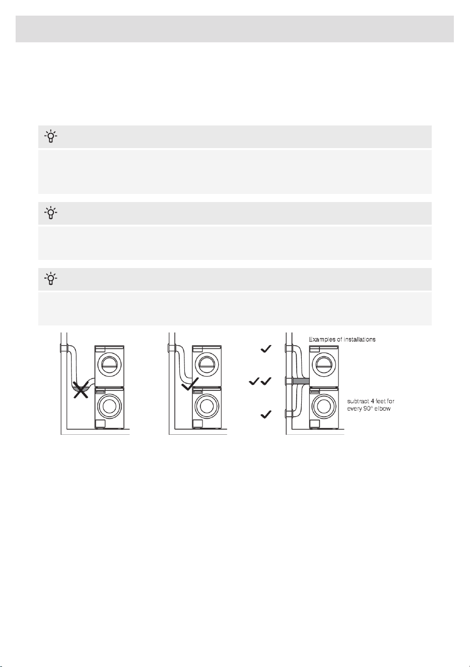
INFORMATION!
Excessive duct length and too many bends can impede drying performance. We recommend
that you cut off any excess exhaust duct and run the duct with as few bends as possible. Make
any necessary bends as gentle as possible.
INFORMATION!
Maximum duct length of 60 feet (18 m). A maximum of 4 elbows may be used, but 4 feet (1,21
m) of duct must subtracted from the total vent length for every 90° elbow used.
WARNING!
To reduce the risk of fire, this appliance must be exhausted OUTDOORS or the equivalent. Never
cover the end of the dryer stub or exhaust duct with anything to catch lint, except for UL approved
vent basket.
18
Installation and connection
Connecting to a ventilation duct
You will need a UL-CSA-approved, 4-inch (101.6 m) ridged metal exhaust duct. If a flexible duct is
used, it must comply with the Outline for Clothes Dryer Transition Duct. Subject 2158A and maximum
length of 94 1/2" (2.4 m).
INFORMATION!
The more bends and the longer the duct, the less air will circulate through the machine, which
will impede drying performance. We recommend that you cut off any excess exhaust duct and
run the duct with as few bends as possible. And make any necessary bends as gentle as possible.
INFORMATION!
Maximum duct length of 60 feet (18 m). A maximum of 4 elbows may be used, but 4 feet (1,21
m) of duct must subtracted from the total vent length for every 90° elbow used.
INFORMATION!
When installing in warm climates (77° F and above) with high humidity levels, do not route the
air exhaust duct upwards.
To connect the exhaust duct to a ventilation outlet, follow the steps below:
• Connect the exhaust duct to a ventilation exhaust fitting or to a discharge through the wall.
• Secure the duct joint to the outlet stub on the machine.
• Run the duct with as few bends as possible to the point of discharge.
19
Installation and connection
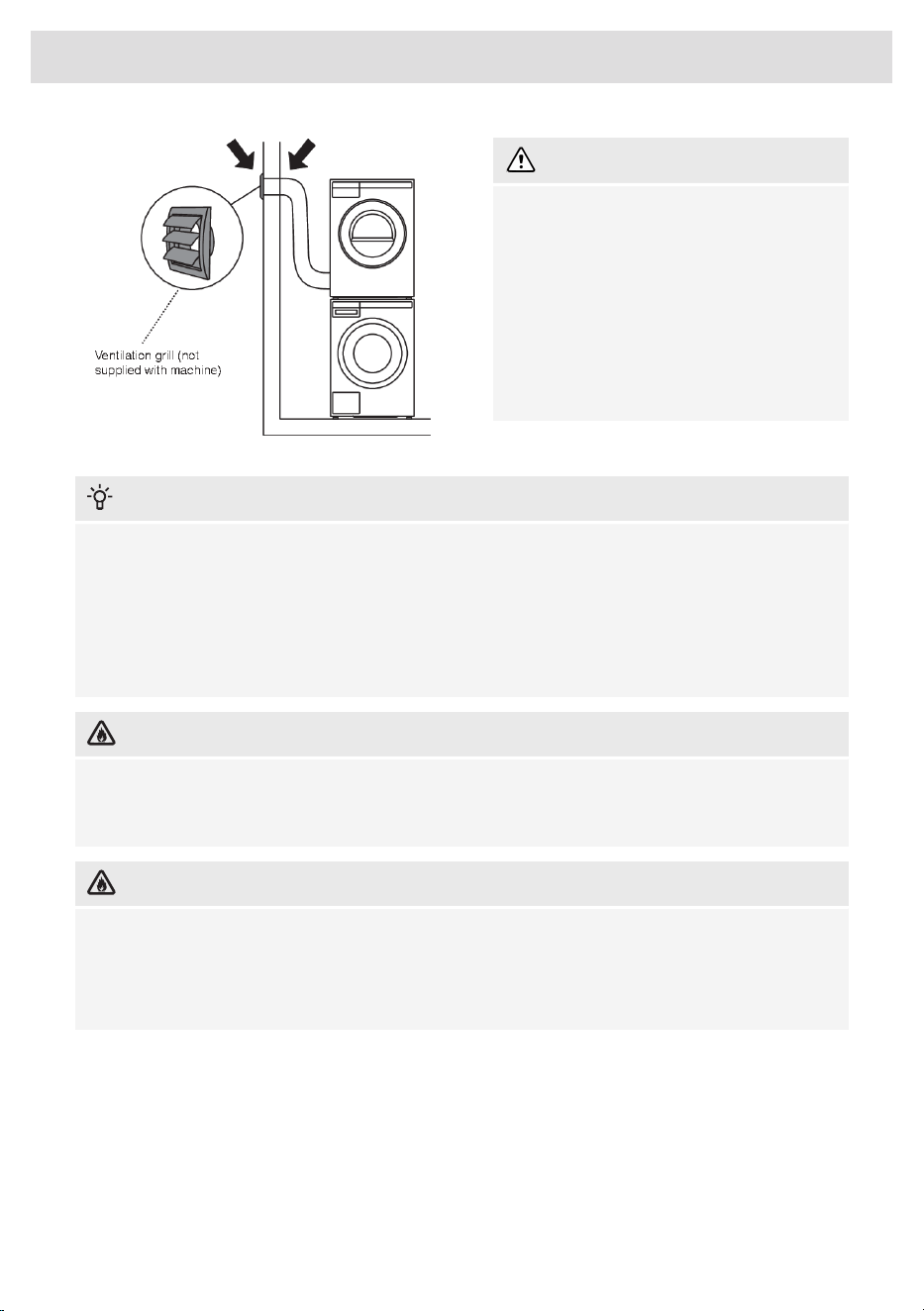
WARNING!
This appliance shall not be exhausted into
a chimney, a wall, a ceiling, an attic, a crawl
space or a concealed space of a building.
Only a rigid or flexible metal duct shall be
used for exhausting. Only a metal
ventilation grill shall be used. If the duct is
taken to a wall outlet, a ventilation grill shall
be fitted to prevent reverse flow of cold air.
Fit the ventilation grill to the outside of the
wall.
INFORMATION!
Avoid:
• very long exhausting systems
• too many corners
• tight corners
These reduce efficiency and increase time and energy consumption.
DANGER OF FIRE!
A clothes dryer produces combustible lint. The dryer must be connected to an exhaust to the
outdoors. Regularly inspect the outdoor exhaust opening and remove any accumulation of lint
around the outdoor exhaust opening and in the surrounding area.
DANGER OF FIRE!
Do not install a booster fan in the exhaust duct.
Note: The booster fan warning does not apply to clothes dryers intended to be installed in a
multiple clothes dryer system, with an engineered exhaust duct system that is installed per the
clothes dryer manufacturer’s guidelines.
20
Installation and connection
Electrical installation
ELECTRIC SHOCK!
The receptacle on the rear of the machine is designed to accommodate ASKO washers ONLY
(rated 208–240 V.) To use this receptacle, you must use the ready-fitted plug supplied with the
washing machine or an equivalent. ASKO washers rated 208–240 V have two internal fuses of
15 A each. The machine should only be connected to a grounded wall socket.
WARNING!
This appliance must be properly grounded. Refer to the “Important Safety Instructions” for
grounding instructions. The power supply cord must be grounded. If the machine is to be used
in a wet area, the supply must be protected by a residual current device. Connection to a
permanently wired supply point must be made only by a qualified electrician.
WARNING!
The receptacle on the rear of the machine is designed to accommodate ASKO washers ONLY
(rated 208–240 V.) To use this receptacle, you must use the ready-fitted plug supplied with the
washing machine or an equivalent.
ASKO washers rated 208–240 V have two internal fuses of 30 A each.
The machine should only be connected to a grounded wall socket.
INFORMATION!
Do not connect the machine to the mains electricity supply by an extension cord.
21
Installation and connection
Electrical Connections
WARNING!
Read the Electrical requirements and grounding instructions before connecting the tumble dryer.
INFORMATION!
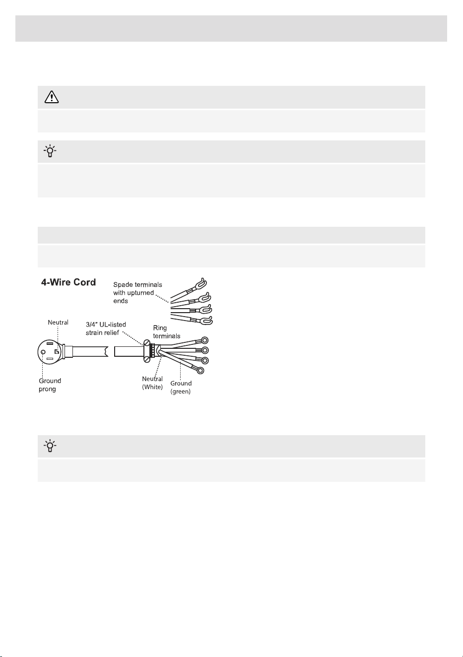
The dryer is delivered ready-fitted with a four-prong plug intended for connection to a 4-wire
NEMA Type 14-30R receptacle.
Connecting a 4-wire Power Cord
NOTE!
Before starting this procedure, be sure the power is turned off at the breaker/fuse box.
Power Supply Cord
INFORMATION!
The numbers in the illustration correlate to the step numbers.
22
Installation and connection
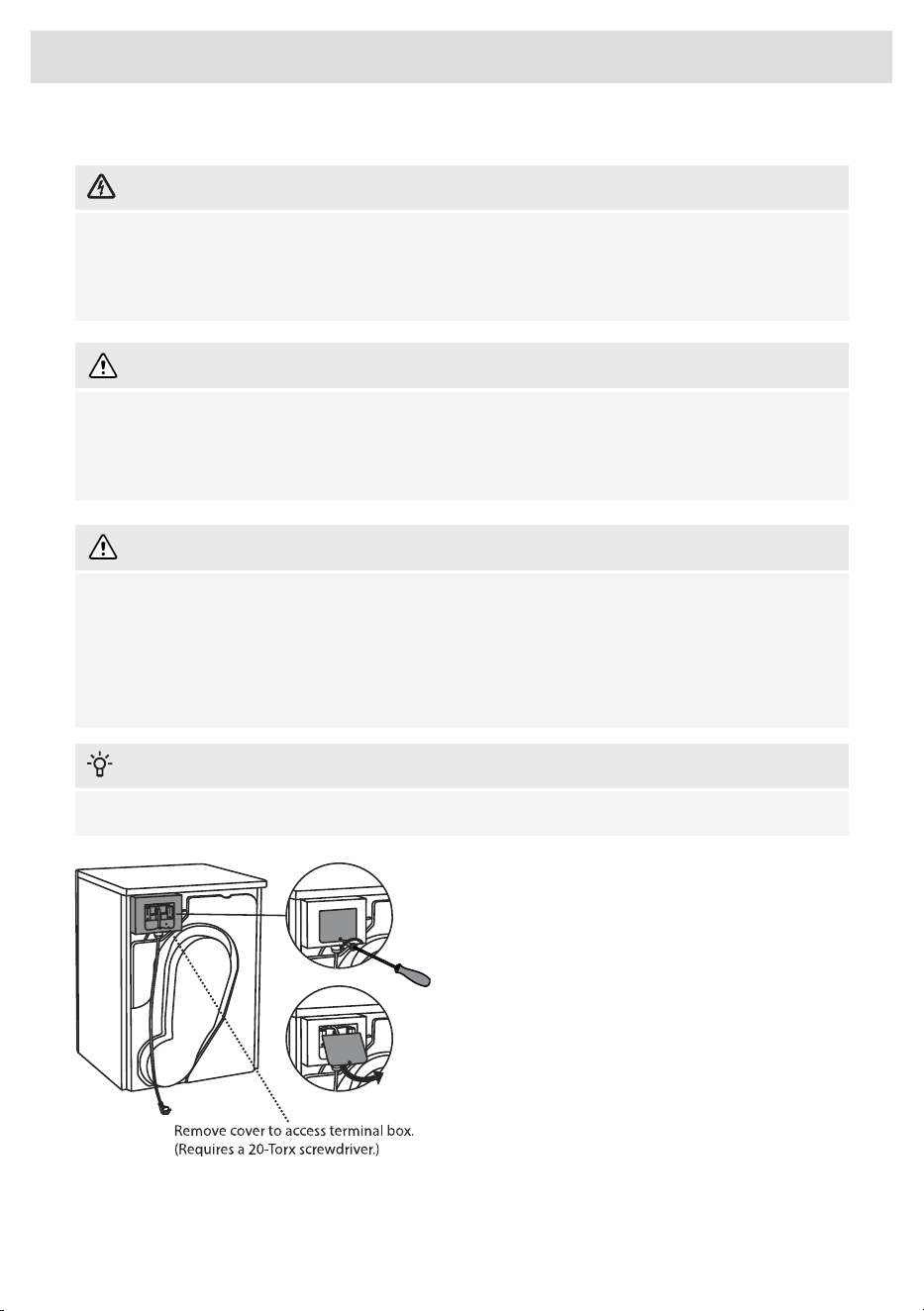
1. Turn the power off at the breaker or fuse
box.
2. Remove terminal block cover.
3. Use the strain relief attached below the
terminal block opening.
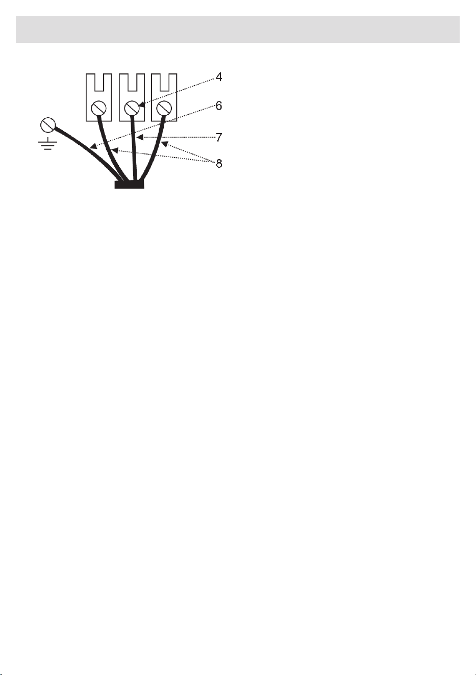
4. Loosen or remove center terminal block
screw.
5. Remove ground wire (green with yellow
stripes) from external ground connector
screw and remove from center terminal
block.
6. Connect ground (green) wire of cord to
external ground conductor screw.
7. Connect neutral (white) wire of cord under
center screw of terminal block.
8. Connect the other wires to outer screws.
9. Tighten the strain relief screws.
10. Replace terminal box cover on back of
dryer.
11. Plug dryer into wall receptacle.
12. Turn power on at breaker/fuse box.
23
Installation and connection

924770
www.us.asko.com
We reserve the right to make changes.
-a2