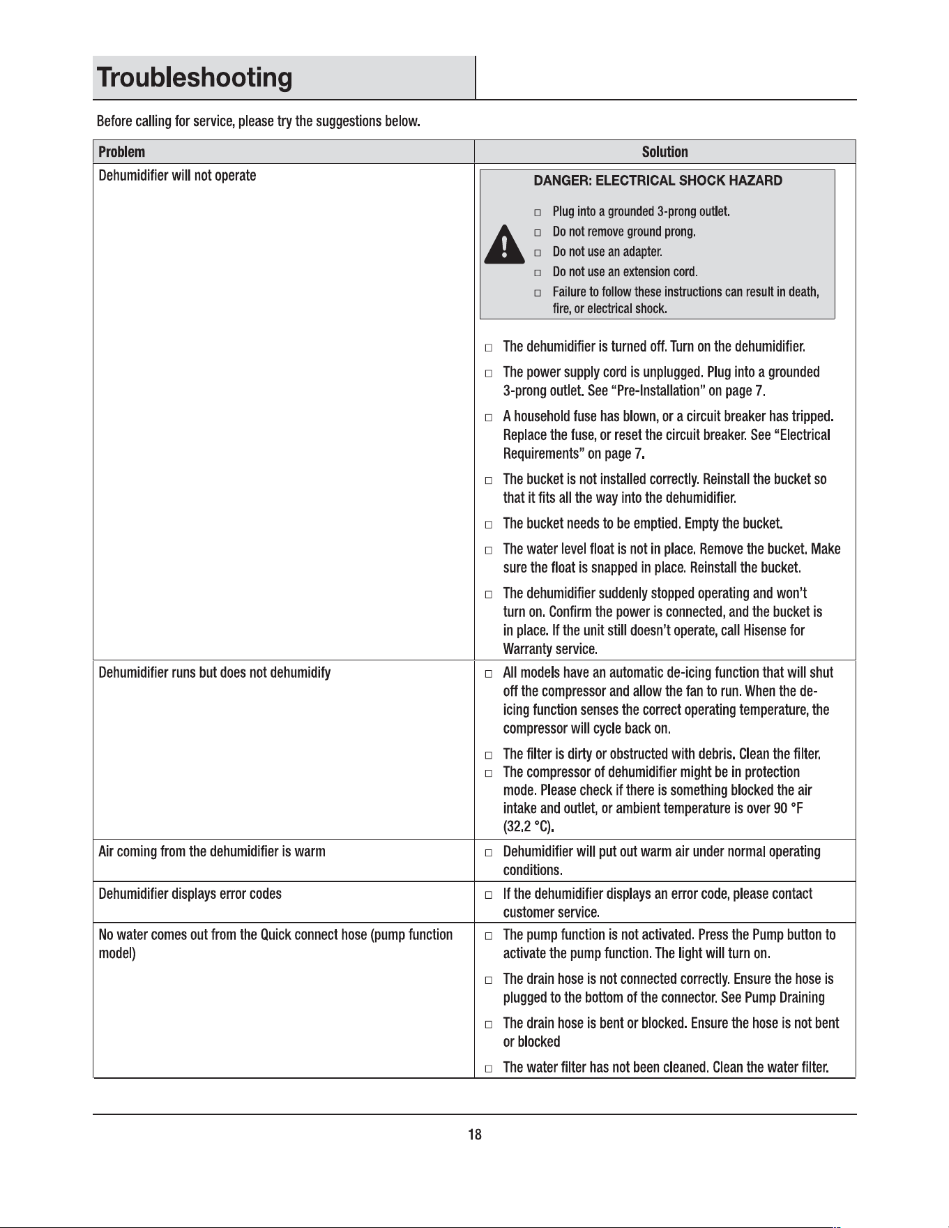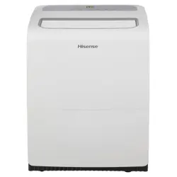

Hisense
USE AND INSTALLATION MANUAL
Model: HD6026P
For questions about features, operation/ performance, parts or
service, call: 1-877-465-3566
Operating hours (EST):
Monday-Friday from 9 a.m. to 9 p.m.
Saturday-Sunday from 9 a.m. to 6 p.m.
Language: English and Spanish
ITM./ART. 1997455

Safety Information (continued) I
□ Replacement pas shall be in accordance with the manufacturer's
specifications.
�
NOTE: The use of silicon sealant may inhibit the eectiveness
U
of some pes of leak detection equipment. Intrinsically safe
components do not have to be isolated prior to working on them.
8. i lnslcally mn
□
Do not apply any permanent inductive or capacitance loads to the
circuit without ensuring that this will not exceed the permissible
voltage and current permied for the equipment in use.
□ Intrinsically safe components are the only types that can be worked
on while live in the presence of a flammable atmosphere.The test
apparatus shall be at the correct rating.
□
Replace components only with pas specified by the manufacturer.
Other pas may result in the ignition of refrigerant in the
atmosphere from a leak.
9. ing
□
Check that cabling will not be subject to wear, corrosion,
excessive pressure,vibration, sharp edges or any other adverse
environmental effects.
□
The check shall also take into account the effects of aging or
continual vibration from sources such as compressors or fans.
10. mle ge
□ Under no circumstances shall potential sources of ignition be used
in these arching for or detection of refrigerant leaks.
□ A halide torch (or any other detector using a naked flame) shall
not be used.
11. don m
□
The following leak detection methods are deemed acceptable for
systems containing flammable refrigerants:
- Electronic leak detectors shall be used to detect flammable
refrigerants, but the sensitivity may not be adequate, or may need
re-calibration. (Detection equipment shall be calibrated in a
refrigerant-free area.)
- Ensure that the detector is not a potential source of ignition and
is suitable for the refrigerant used.
- Leak detection equipment shall be set at a percentage of the
LFL of the refrigerant and shall be calibrated to the refrigerant
employed and the appropriate percentage of gas (25 % maximum)
is confirmed.
- Leak detection fluids are suitable for use with most refrigerants
but the use of detergents containing chlorine shall be avoided as
the chlorine may react with the refrigerant and corrode the copper
pipe-work.
- If a leak is suspected, all naked flames shall be removed/
einguished.
- If a leakage of refrigerant is found which requires brazing, all
of the refrigerant shall be recovered from the system, or isolated
(by means of shutoff valves) in a pa of the system remote from
the leak.
- Oxygen free nitrogen (OFN) shall then be purged through the
system both before and during the brazing process.
12. Re d
□
When breaking into the refrigerant circuit to make repairs - or for
any other purpose - conventional procedures shall be used.
However , for flammable refrigerants it is impoant that best
5
practice be followed , since flammability is a consideration.
The following procedure shall be adhered to:
a) safely remove refrigerant following local and national
regulations;
b) purge the circuit with ine gas;
c) evacuate ( optional for A2L);
d) purge with ine gas ( optional for A2L);
e) open the circuit by cuing or brazing;
□ The refrigerant charge shall be recovered into the correct
recovery cylinders if venting is not allowed by local and national
codes. For appliances containing flammable refrigerants, the
system shall be purged with oxygen - free nitrogen to render the
appliance safe for flammable refrigerants. This process might
need to be repeated several times. Compressed air or oxygen
shall not be used for purging refrigerant systems.
□ For appliances containing flammable refrigerants, refrigerants
purging shall be achieved by breaking the vacuum in the system
with oxygen - free nitrogen and continuing to fill until the working
pressure is achieved, then venting to atmosphere, and finally
pulling down to a vacuum (optional for A2L). This process shall be
repeated until no refrigerant is within the system (optional for
A2L). When the final oxygen - free nitrogen charge is used, the
system shall be vented down to atmospheric pressure to enable
work to take place.
□ Ensure that the outlet for the vacuum pump is not close to any
potential ignition sources and that ventilation is available.
13. Cing pu
□
In addition to conventional charging procedures, the following
requirements shall be followed:
- Ensure that contamination of dierent refrigerants does not
occur when using charging equipment.
- Hoses or lines shall be as sho as possible to minimise the
amount of refrigerant contained in them.
- Cylinders shall be kept up right.
- Ensure that the refrigeration system is eahed prior to
charging the system with refrigerant.
- Label the system when charging is complete (if not already).
- Ereme care shall be taken not to oveill the refrigeration
system.
□ Prior to recharging the system it shall be pressure tested with OFN.
□ The system shall be leak tested on completion of charging but
prior to commissioning.
□ A follow up leak test shall be carried out prior to leaving the site.
14.Dmmnlng
□
Before carrying out this procedure, it is essential that the technician
is completely familiar with the equipment and all its detail.
□ It is recommended good practice that all refrigerants are recovered
safely.
□
Prior to the task being carried out, an oil and refrigerant sample
shall be taken in case analysis is required prior to re-use of
reclaimed refrigerant. It is essential that electrical power is
available before the task is commenced.
a) Become familiar with the equipment and its operation.
b) Isolate system electrically.
c) Before aempting the procedure ensure that:
- Mechanical handling equipment is available, if required,
Operation (continued)
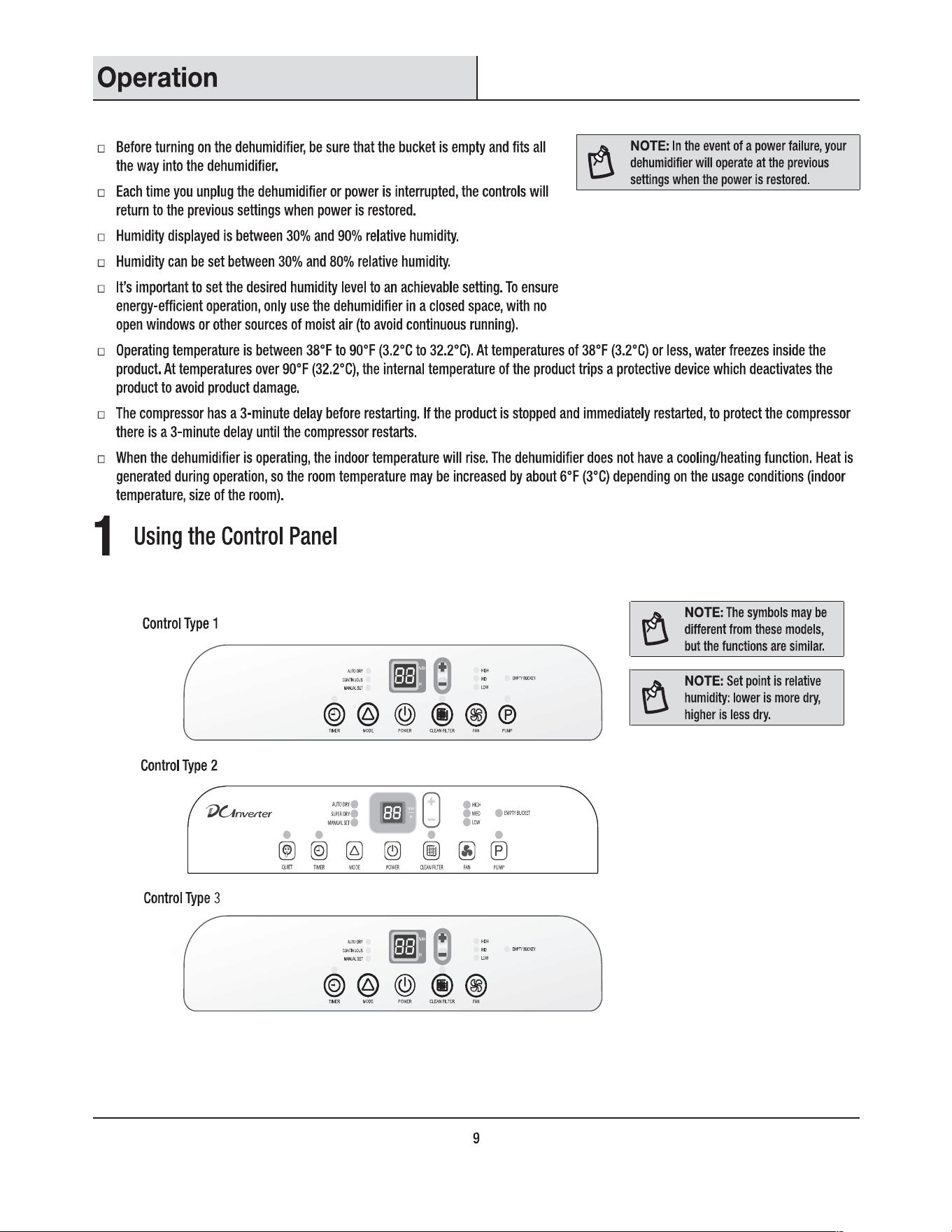
POWER
MODE
AUTOORY Q
CONTINUOUS 0
SUPERDRY
•
MANUALSET 0
POWER ON OR OFF
Press POWER to turn on or o the dehumidifier.
DESIRED HUMIDITY MODE
□ Press and release MODE until you see the symbol for the desired humidity seing. Operating modes are Auto Dry,
Continuous or Manual Set.
□ Auto Dry - The dehumidifier will operate in dry mode only. The desired humidity is set to 50% automatically and
can not be adjusted.
□ Continuous/ Super Dry - The dehumidifier will operate continuously. The fan speed can be adjusted. The desired
humidity is set to 30% automatically and can not be adjusted.
□ Manual Set- The dehumidifier will operate at the selected fan speed to the set humidity level. If the humidity level of
the room is higher than the desired humidity seing, the compressor will turn on. If the humidity level of the room is
lower than the desired humidity seing, the compressor will turn off, as well as the fan.
�
NOTE: The de-icing function will turn o the compressor if a low temperature condition occurs. When the de-icer senses
D
the correct operating temperature the compressor will cycle back on. Some freezing is normal when dehumidifiers are used
at low temperatures.
0 EMPTYBUCKET
EMPTY BUCKET LIGHT
FAN
+
QUIET
If this light is on, the fan and the compressor will stop running. This light indicates that you need to check:
□ If the bucket is full, empty and re-install bucket. If the bucket is not in position, remove the bucket and re-install it.
Make sure the bucket fits all the way into the dehumidifier and the bucket light is o, or dehumidifier will not run.
FAN SPEED
□ Press FAN to select fan speed.
□ Choose LOW, MED/ MID or HIGH.
□ LOW-Reach the desired humidity seing with lower sound level.
□ MED/ MID-Achieves set humidity at normal speed.
□ HIGH-Reach the desired humidity seing faster.
�
NOTE: Once the relative humidity of the room hits the desired seing, the compressor will stop and
D
the fan will be o
�
periodically. The fan may periodically turn on, to read the humidity level, without the
compressor running.
HUMIDITY LEVEL
□ Press the Plus or Minus buon to set the desired humidity level. Desired humidity in the digital display will flash for 5
seconds aer operation.
□ Actual room humidity will be displayed aer 5 seconds of flashing the desired humidity.
�
NOTE: Humidity can only be adjusted manually in Manual Set mode. In Continuous and Auto Dry mode,
humidity level is set automatically.
QUIET
□ Press QUIET to run the dehumidifier in lower noise operation.
�
NOTE: Once the MODE or FAN SPEED are changed, the dehumidifier will quit QUIET mode automatically.
10
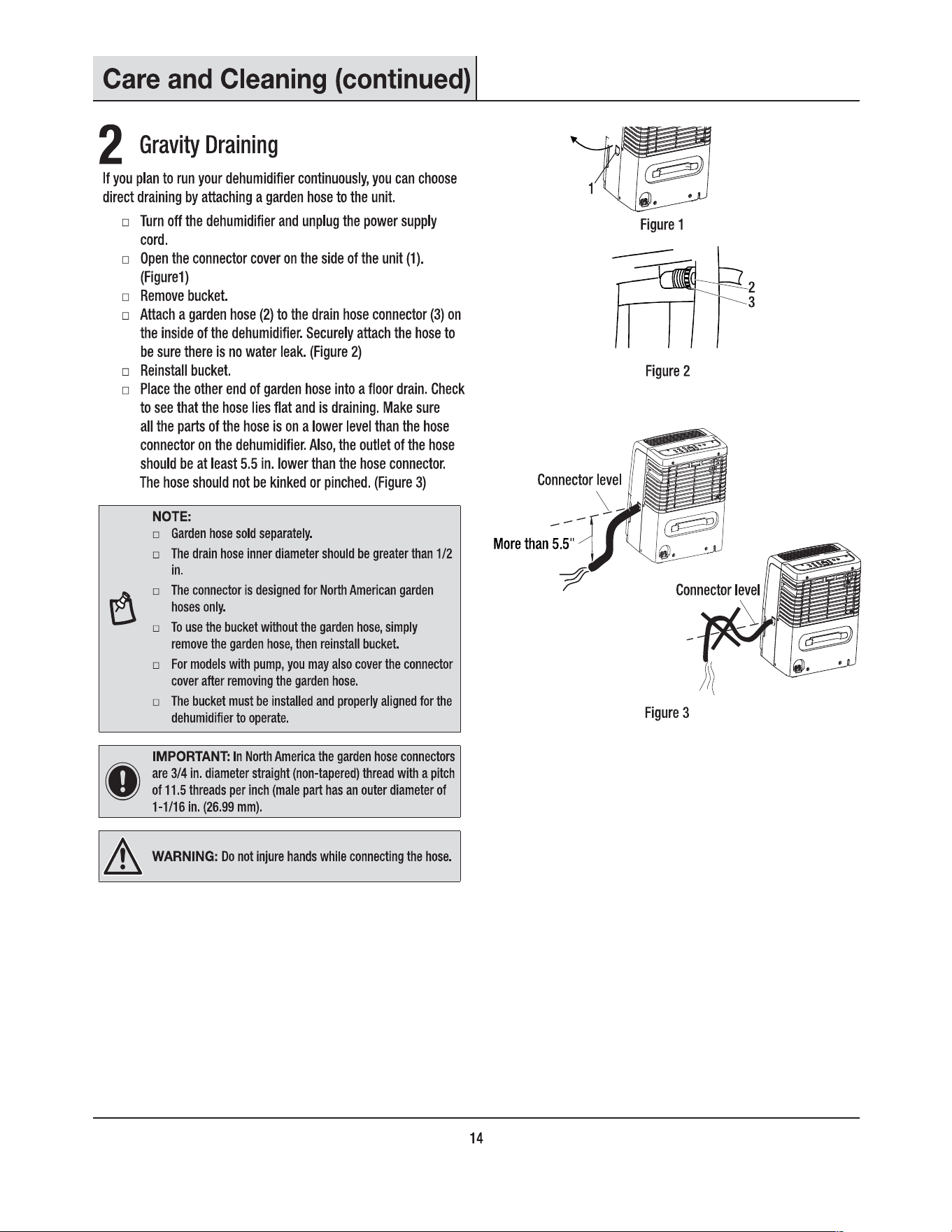
Before removing the filter, please put a draining
dish
under the unit and make sure there is not water
draining from the port.
Care and Cleaning (continued)
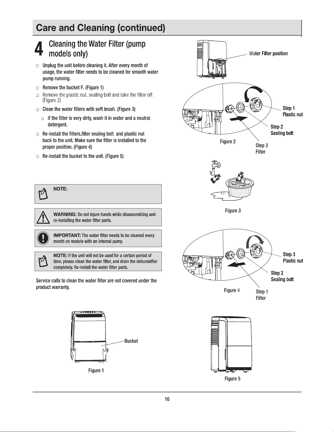
5 Cleaning the Air Filter
The air filter is removable for easy cleaning. A clean filter helps
remove dust, lint, and other paicles from the air and is impoant
for best operating eiciency. Check the filter every two weeks to
see whether it needs cleaning.
□ Turn o the dehumidifier.
□ Remove the air filter.
□ Use a vacuum cleaner to clean the air filter. If the air
filter is di, or wash it in warm water with a mild
detergent.
□ Reinstall the air filter.
□ Turn on the dehumidifier.
6
NOTE: Do not wash air filter in the dishwasher or use any
chemical cleane Air dry filter completely before reinstalling
to ensure maximum operating eiciency.
Cleaning the Exterior
□ Turn o the dehumidifier and unplug the power supply cord.
□ Dust the suace of the unit with a so cloth or the dusting aachment of your vaccum cleaner.
7
Cleaning the Water Bucket
Every few weeks, rinse the inside of the water bucket with a mild
detergent to avoid growth of mold, mildew and bacteria.
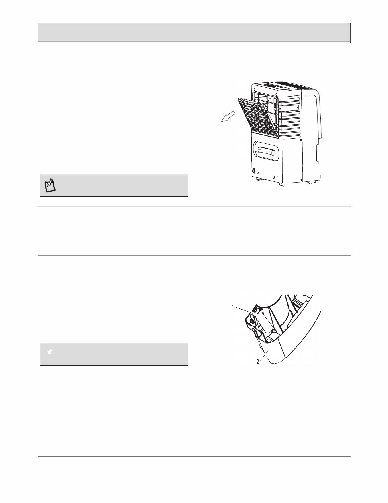
Water level float
The dehumidifier has a EMPTY BUCKET light and a water float (1).
The bucket (2) must be properly aligned for the water level float
and the EMPTY BUCKET light to work.
�
NOTE: Be sure the float and handle is snapped correctly in
U place ..
17