ASSEMBLY INSTRUCTIONS
Effective September 2024
ASSEMBLY INSTRUCTIONS
READY-TO-FINISH CUSTOM OUTDOOR KITCHENS
DANGER: If you plan to install any natural gas or propane appliances into this island, the island itself
must be ventilated properly in accordance with appliance manufacturer requirements and local codes.
Any island that has any sort of gas supply or connection must have a minimum of 1 vent. Improper
ventilation may cause property damage, injury or death.
WARNING: Excessive weight hazard! Use two or more people to move, assemble or install
panels
and parts to avoid back injury.
Do not leave children unattended nearby while assembling. Choking hazard-small parts.
For more information, questions or assistance please visit us at
RCSGasGrills.com and click the Customer Care Form
ASSEMBLY INSTRUCTIONS
Effective September 2024
The order you assemble your kitchen modules can depend on the overall shape of your kitchen. Begin
by assembling the cabinets that will determine your countertop height. Next, focus on assembling any
modules that include backsplashes or bar components. This can simplify attaching these elements later
in the process. Once you've determined your assembly order, you can refer to the following steps for
detailed instructions:
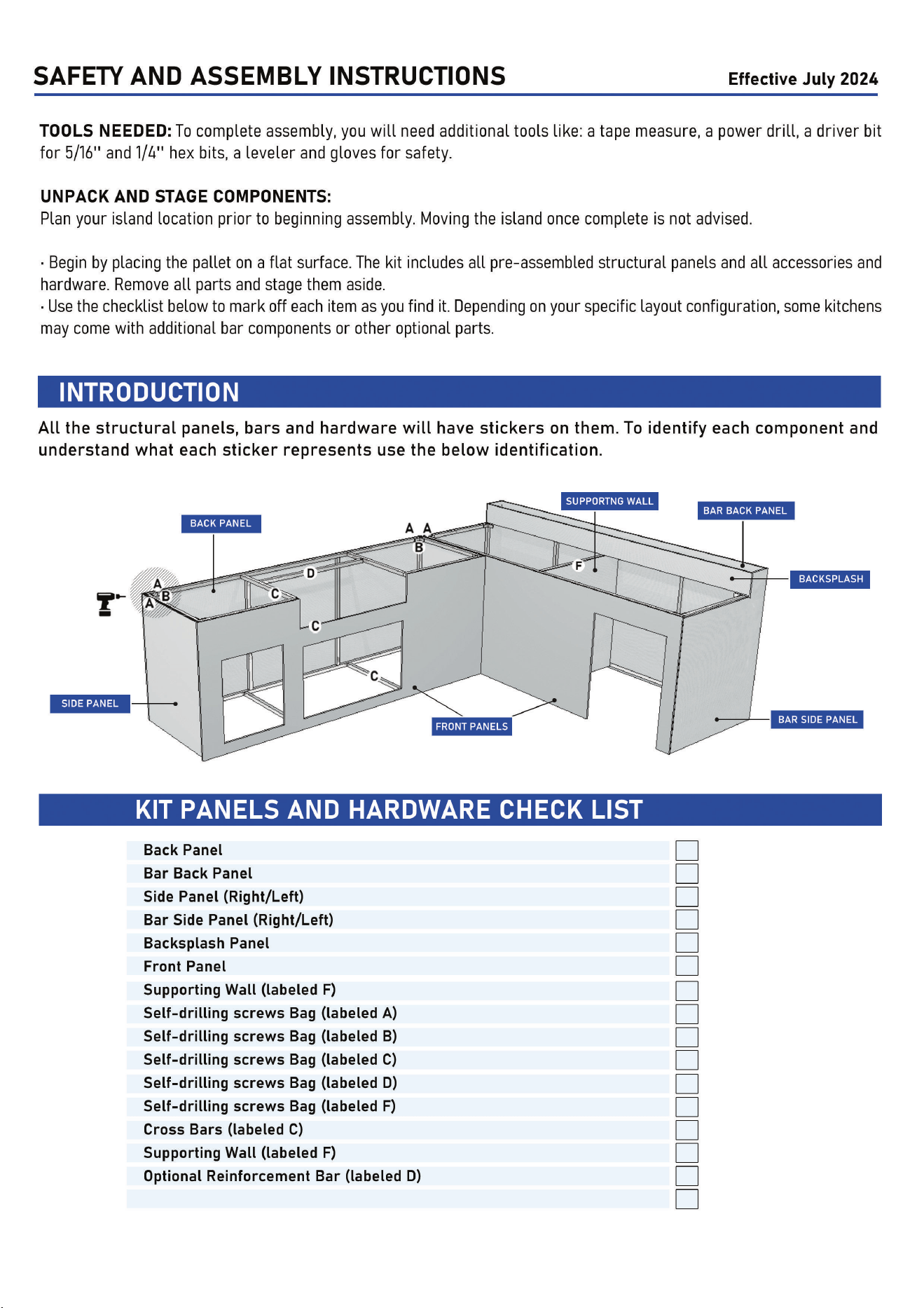
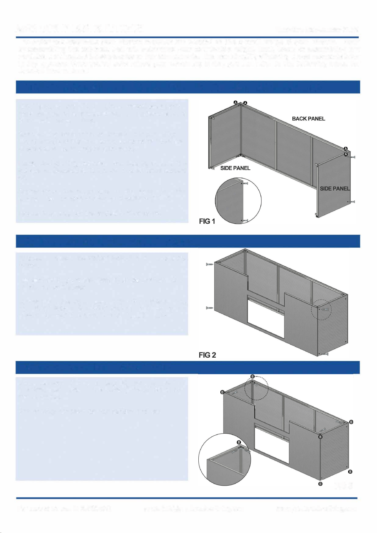
STEP 1 : ASSEMBLE FIRST MODULE BACK AND SIDE PANELS
Identify either the left or right universal side panel.
Each side panel is equipped with L brackets labeled
B and self-leveling feet.
Connect the back panel to the side panels. Align
the channels of the side panels and shim them as
needed to ensure proper alignment.
Using self-drilling screws from bag A, secure the
side panel (labeled A) to the back panel (also labeled
A).
Screw from the outer side of the panel into the
support bar on both the top and bottom (FIG 1)
Repeat this step for the opposite side panel.
STEP 2 : AACH THE FRONT PANEL
Proceed to attach the FRONT PANEL to the rest of the
frame.
Use self-drilling screws (bag A) to secure the FRONT
PANEL on both sides.
Screw from the outer side of the SIDE PANEL into
the FRONT PANEL SUPPORT BAR on both the top and
bottom. Repeat this step for the opposite side.
STEP 3 : SECURE L BRACKETS
Using screws (found in bag B) secure the the
pre-attached metal L brackets (labeled B) to the
frame (FIG 3).
Repeat step for each corner bottom and top.
FIG 3
ASSEMBLY INSTRUCTIONS
Effective September 2024
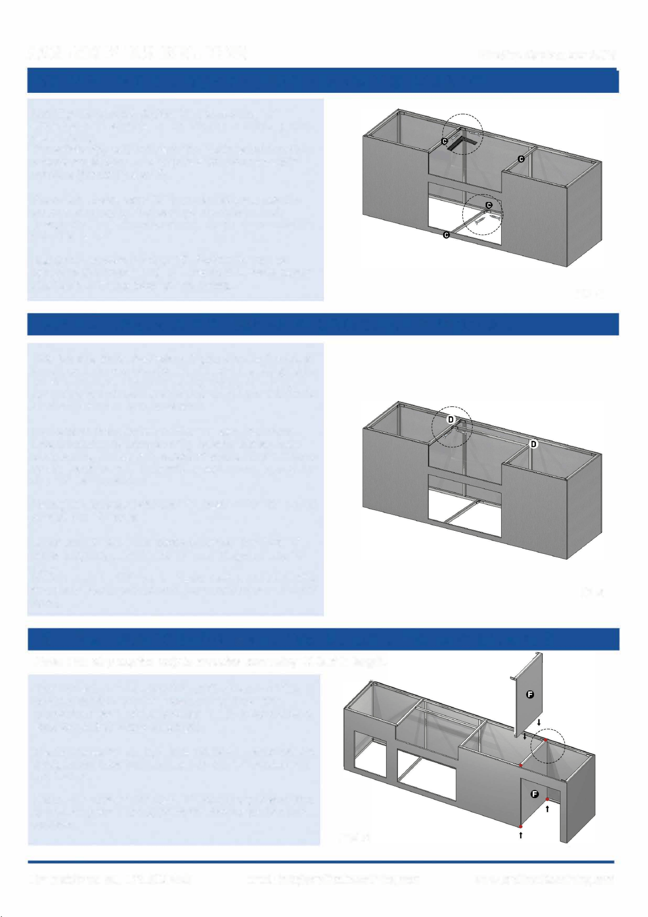
STEP 4: INSTALL TOP AND BOOM CROSS BARS
11
C
11
Identify the CROSS BARS "C". Locate the "C"
stickers on the inside of the kitchen module you're
assembling.
The sticker(s) will indicate the designated location
where cross bars are required for your specific
module (typically 2 or 3).
Place the cross bars "C" horizontally across the
bottom and top of the cabinet module in their
designated locations ensuring they run parallel to
the side panels.
Using the screws labeled "C", fasten the cross
bar(s) to the frame (FIG 4). Ensure the cross bar(s)
sits flush with the edge of the frame.
STEP 5: INSTALL
11
D
11
BAR REINFORCEMENT (OPTIONAL)
This step is only necessary if you plan to install a
small countertop section behind your grill, griddle
or side burner. If you intend to use a full-length
countertop or have no appliances planned for this
section, you can skip this step.
For easier installation of the "D" bar, you may
find it helpful to temporarily loosen the screws
connecting the back bracket of one of the "C" bars
to the back panel. This will create more space for
the "D" bar to slide in.
Using the screws labeled "D", fasten the "D" bar to
one of the "C" bars.
Slide the "D" bar into place between the two "C"
bars, aligning it with the "D" markings on the "C"
bars.
Make sure the "D" bar is positioned parallel to the
front and back panels and perpendicular to the "C"
bars.
STEP 6: SUPPORTING WALL INSTALLATION (IF APPLICABLE)
Note: This step applies only to modules exceeding 10 feet in length.
Find the sticker labeled "F" on the frame of the
kitchen module you're assembling. Take the
supporting wall panel labeled "F" (it resembles a
side panel but lacks a flange).
Stand the panel upright and position it against the
designated location marked by the "F" sticker on
the frame.
Using the screws labeled "F", securely fasten the
supporting wall panel(s) to the frame on top and
bottom.
FIGG
FIG4
FIGS
ASSEMBLY INSTRUCTIONS
Effective September 2024
Great work! You've assembled one of your kitchen modules. Now, let's proceed based on your kitchen
configuration:
- SINGLE MODULE KITCHEN: If your kitchen has only one module, you're ready for the finishing touches:
countertops, appliances, and finishes.
- MULTIPLE MODULES: For kitchens with multiple modules, simply repeat the assembly steps you've just
completed for this module on each remaining module in your layout.
- BAR MODULE ASSEMBLY
(
OPTIONAL): If your kitchen has a dedicated bar area, proceed to Steps 7-9.
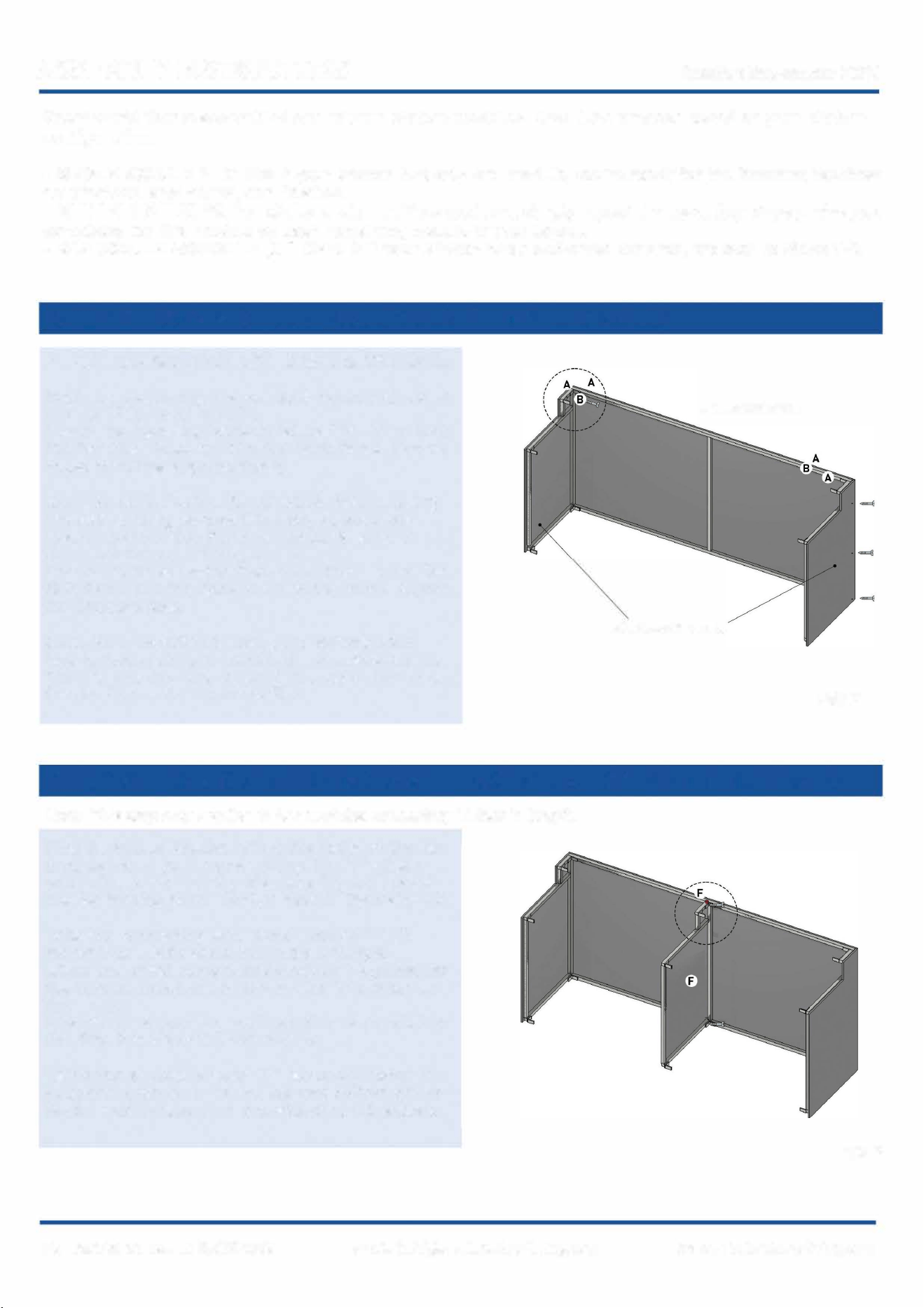
STEP 7: BAR MODULE ASSEMBLY (IF APPLICABLE)
ATTACH BAR SIDE PANEL
(
S
)
TO BAR BACK PANEL:
Begin by positioning the Bar Back Panel and one of
the Bar Side Panel upright.
Locate the matching stickers labeled "A-A" on both
the Bar Side Panel and the Bar Back Panel. Ensure
these markings align perfectly.
SECURE SIDE PANEL
(
S
)
TO BACK PANEL: Using
the self-drilling screws from Bag A, securely
fasten the Bar Side Panel to the back panel at
three points: top, middle, and bottom.
Ensure you're screwing from the outside of the Bar
Side Panel into the Back Panel metal frame. Repeat
for Opposite Side.
SECURE L BRACKETS: Using the screws from
Bag B, fasten the pre-attached L brackets on the
Side Panels
(
top and bottom
)
directly to the metal
frame. Repeat for Opposite Side.
BAR BACK PANEL
BAR SIDE PANELS
FIG7
STEP 8 : BAR SUPPORTING WALL INSTALLATION (IF APPLICABLE)
Note: This step only applies to bar modules exceeding 10 feet in length.
Find the sticker labeled "F" on the inside of the bar
module frame you're assembling. The "F" sticker
will indicate the quantity of supporting wall panels
needed for this particular bar module
(
typically 1-2
)
.
Take the supporting wall panel labeled "F"
(
it
resembles a side panel but lacks a flange
)
.
Stand the panel upright and position it against the
designated location marked by the "F" sticker on
the frame.
Ensure the supporting wall panel runs parallel to
the Side Panels of the bar module.
Using the screws labeled "F", securely fasten the
supporting panel "F" to the top and bottom of the
Back Panel through the pre-attached L brackets.
FIGS
ASSEMBLY INSTRUCTIONS
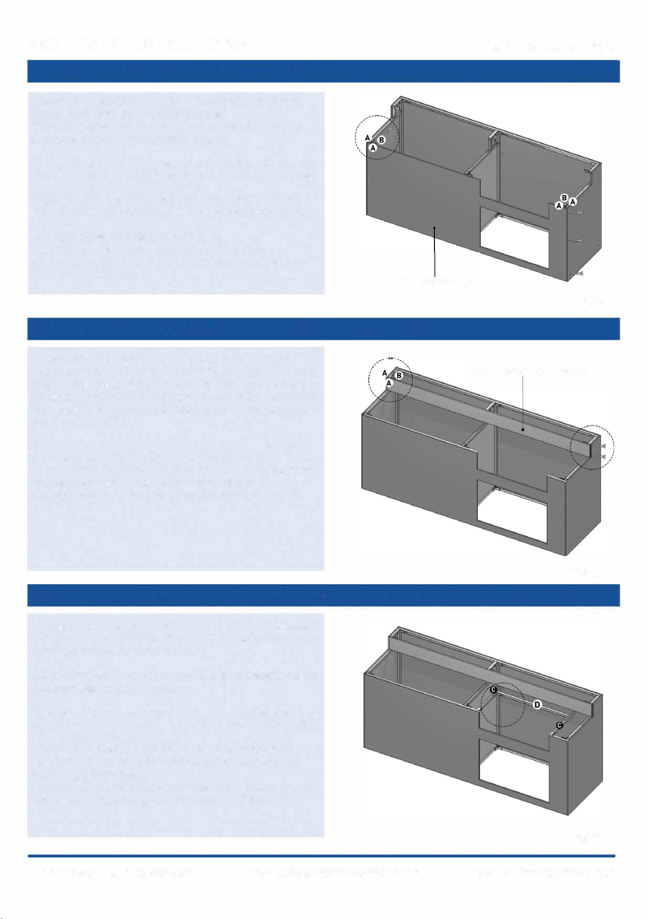
STEP 9 : BAR FRONT PANEL INSTALLATION
Locate the sticker labeled "A" on both the front
panel and each of the side panels.
Carefully position the front panel so that the "A"
stickers on all three panels align.
Using the self-drilling screws from Bag A, fasten
the front panel to each side panel at three points:
top, middle, and bottom (Fig 9)
Ensure you're screwing from the outside of the
side panel into the metal frame of the front panel.
ATTACH REMAINING L BRACKETS:
Effective September 2024
Use the screws from Bag B to secure the
pre-attached L brackets on the Bar Side Panels
to the front panel.
BAR FRONT PANEL
STEP 10: BAR BACKSPLASH PANEL INSTALLATION
Locate the Backsplash and place it in position.
Using self-tapping hex screws from Bag A, secure
the Backsplash Panel to each of the Side Panels
by screwing from the outside of the side panel into
the metal frame of the backsplash at the top and
bottom. (FIG 10)
Secure the remaining L brackets on the bar side
panels (identified by stickers labeled "B").
Screw from the inner corner of the L brackets into
the backsplash panel using screws bag B.
Repeat this step for the opposite corner. (FIG 10)
FIG9
BAR BACKSPLASH PANEL
FIG10
STEP 11 : BAR MODULE CROSSBARS INSTALLATION (OPTIONAL)
This step equips your bar module with crossbars
for holding appliances (if your bar design includes
a grill, griddle, or side burner).
Skip this step if your bar module is not designed to
accommodate appliances.
The installation process for these crossbars is very
similar to the procedures you followed in Steps 4
and 5 of this manual.
Locate the designated areas for the crossbars
"C" and "D" on your bar module frame (refer to
markings provided).
Position the crossbars in place and secure them
using corresponding screws bags "C" and "D".
FIG 11
ASSEMBLY INSTRUCTIONS
Effective September 2024
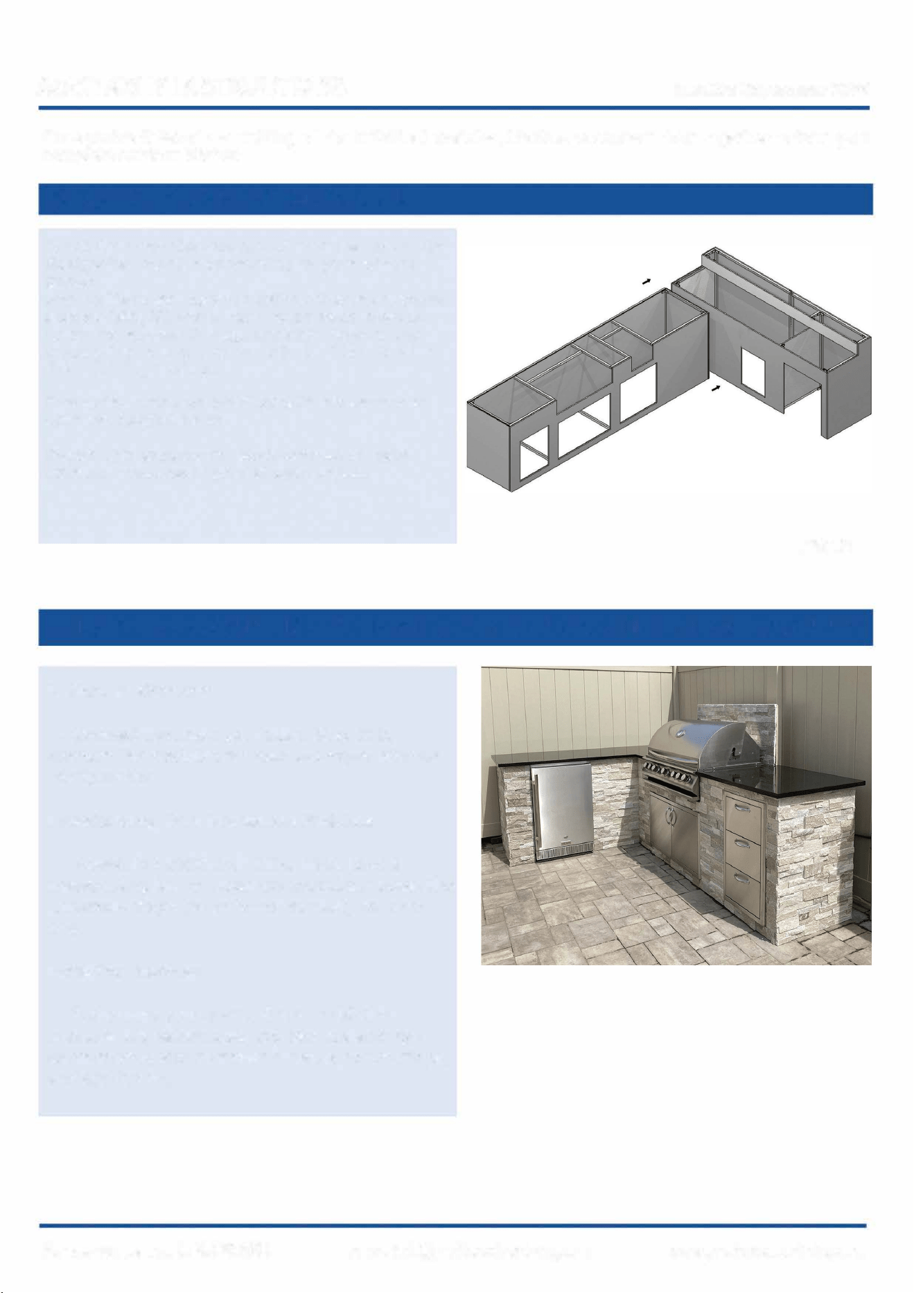
Once you've finished assembling all the individual modules, it's time to connect them together to form your
complete outdoor kitchen.
STEP 12 : CONNECT MODULES
Carefully move the assembled modules into their
designated positions according to your kitchen
layout.
Secure Modules Together using the cement board
screws (Bag G), work from inside each module.
Drive the screws through the Side Panel of the
module frame and into the exterior Side Panel of
the adjoining module.
Fasten the modules together with six screws at
each connection point.
Repeat this process for each connection point
between modules in your kitchen layout.
FIG12
STEP 13: PERSONALIZE YOUR KITCHEN (ADDING FINISHING TOUCHES)
U
-
Shaped Kitchens:
- Connect the modules: Follow Step 12 to
connect the modules for your U-shaped kitchen
configuration.
Freestanding Bars & Separate Modules:
- Assemble additional units: If you have a
freestanding bar or separate modules, repeat the
assembly steps (refer to the manual) for each
one.
Finishing Touches:
- Customize your space: Once the kitchen
modules are assembled, you can add storage
components, stone veneer finishes, countertops,
and appliances.