
Technical Support and E-Warranty Certificate
www.vevor.com/support
ROTARY TABLE
MODEL: HV-4-KP, HV-4-4, HV-4-4R,
HV-6-4, HV-6-4B, HV-8-4, HV-8-3
We continue to be committed to provide you tools with competitive price.
"Save Half", "Half Price" or any other similar expressions used by us only represents an
estimate of savings you might benefit from buying certain tools with us compared to the
major top brands and does not necessarily mean to cover all categories of tools offered by
us. You are kindly reminded to verify carefully when you are placing an order with us if you
are actually saving half in comparison with the top major brands.
- 1 -
ROTARY TABLE
MODEL:HV-4-KP, HV-4-4 , HV-4-4R, HV-6-4, HV-6-4B,HV-8-4 HV-8-3
NEED HELP? CONTACT US!
Have product questions? Need technical support? Please feel free to
contact us:
Technical Support and E- Warranty Certificate
www. vevor. com/ support
This is the original instruction, please read all manual instructions
carefully before operating. VEVOR reserves a clear interpretation of our
user manual. The appearance of the product shall be subject to the
product you received. Please forgive us that we won't inform you again if
there are any technology or software updates on our product.
- 2 -
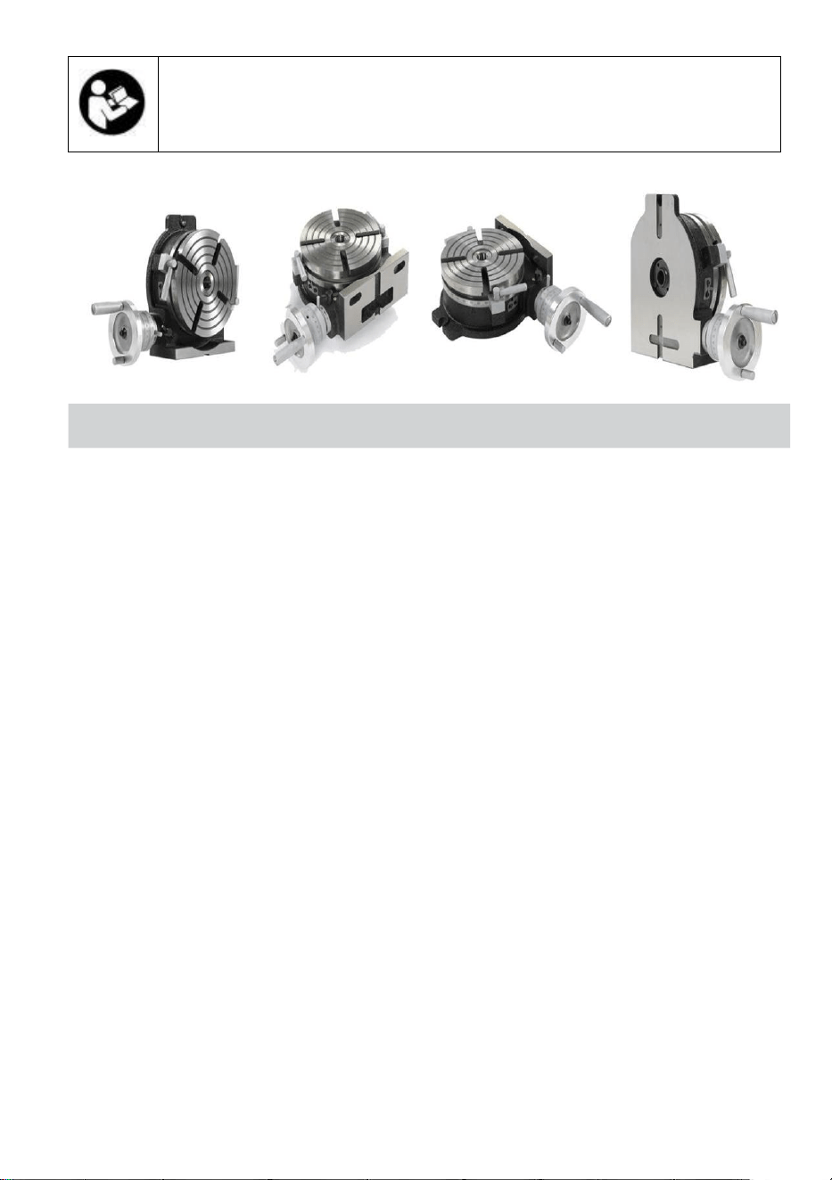
Warning-To reduce the risk of injury, user must read
instructions manual carefully.
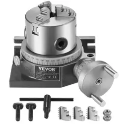
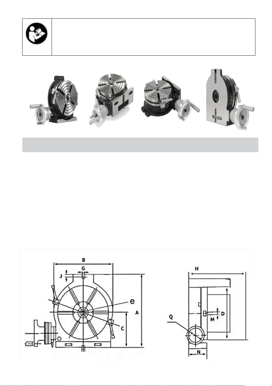
PRECISION ROTARY TABLES
Two types of Rotary tables are summarized here collectively. The
mechanisms common to these tables are shown on some pages of
their description.
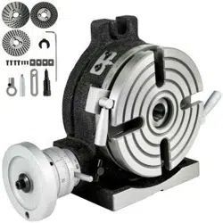
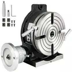
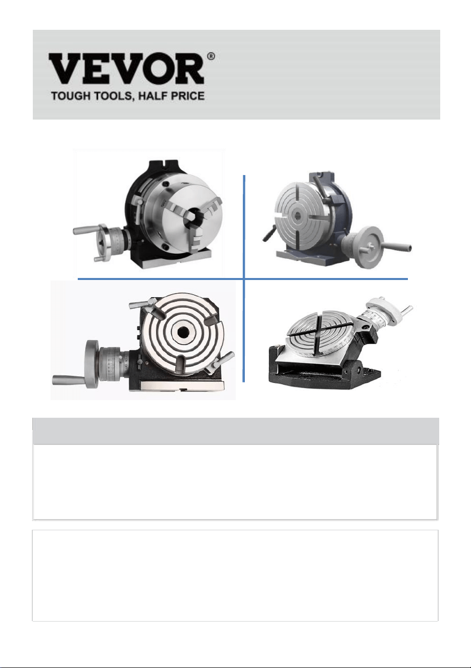
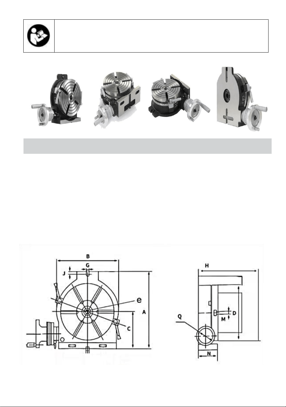
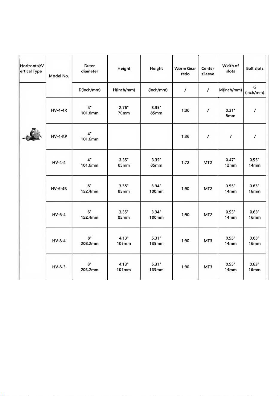
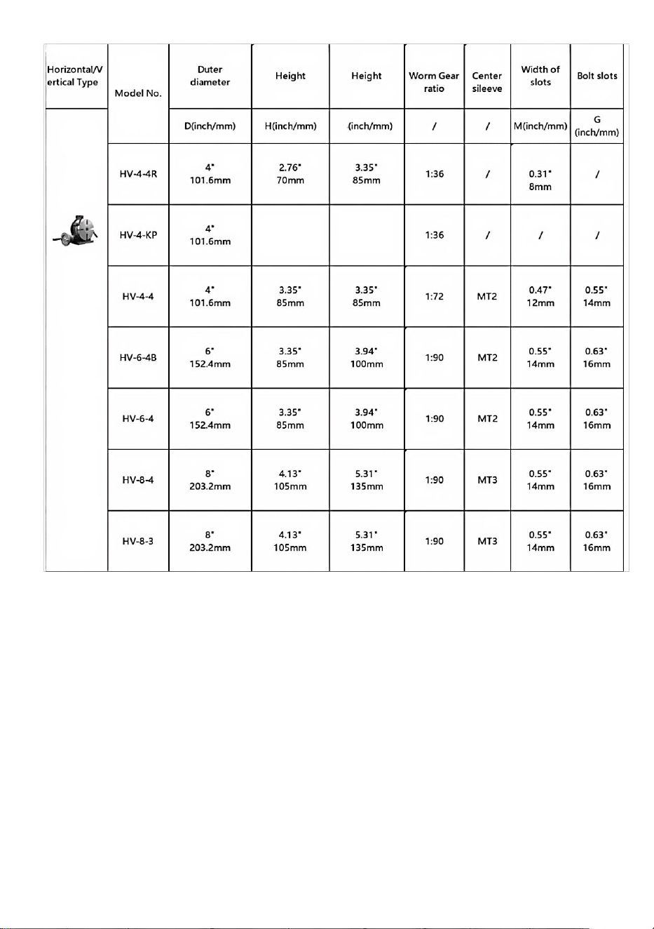
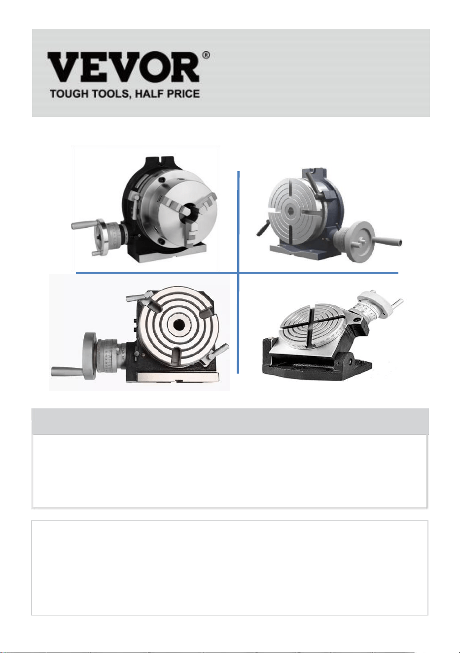
HORIZONTAL/VERTICAL PRECISION ROTARY TABLE
This rotary table is designed to permit machining operations at a higher
dimension than that of Horizontal Type rotary tables. The base can be
used in a vertical position to enable it to carry out center work.
- 3 -
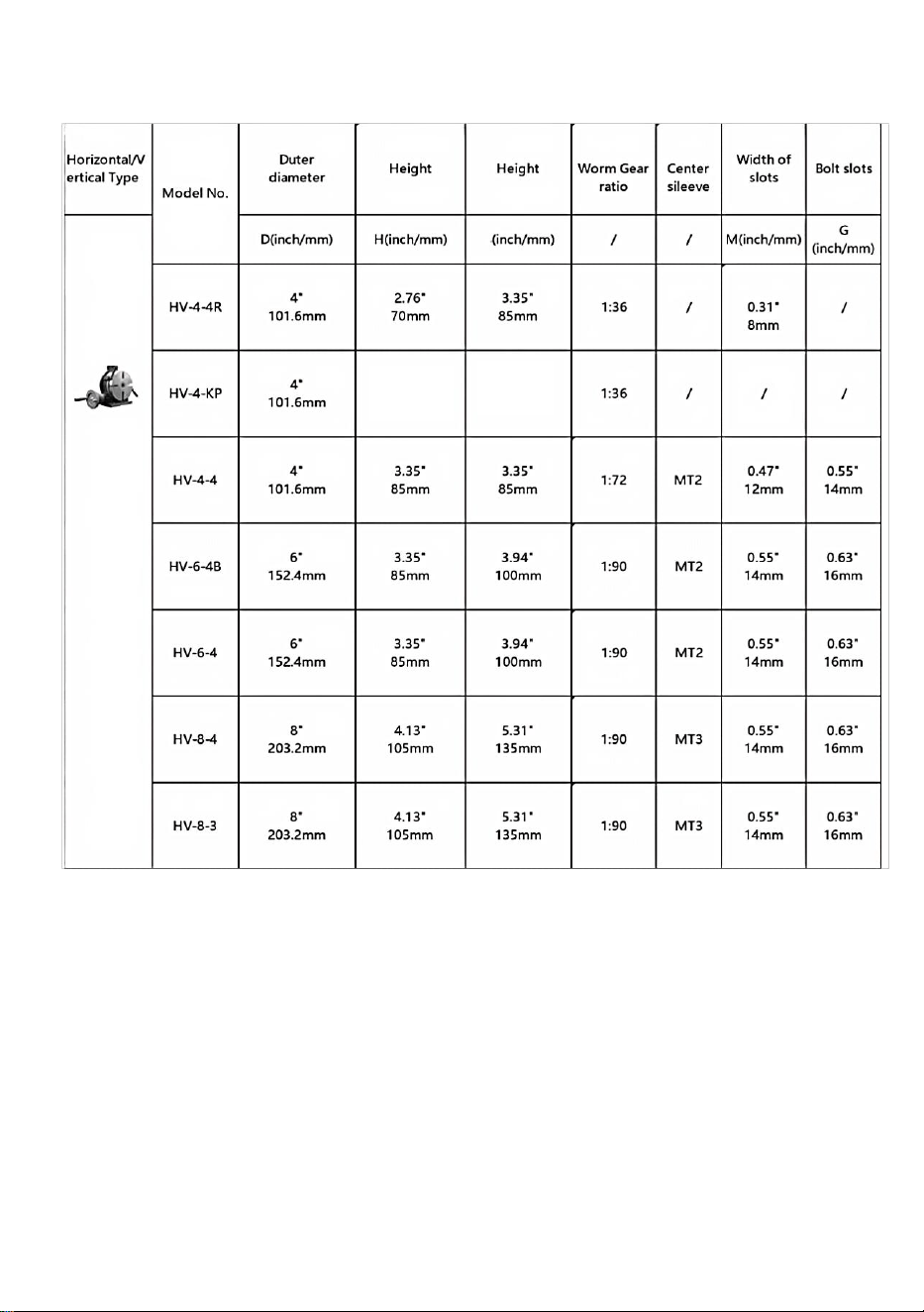
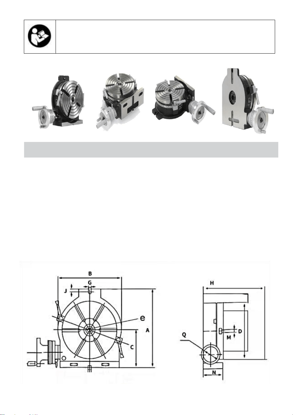
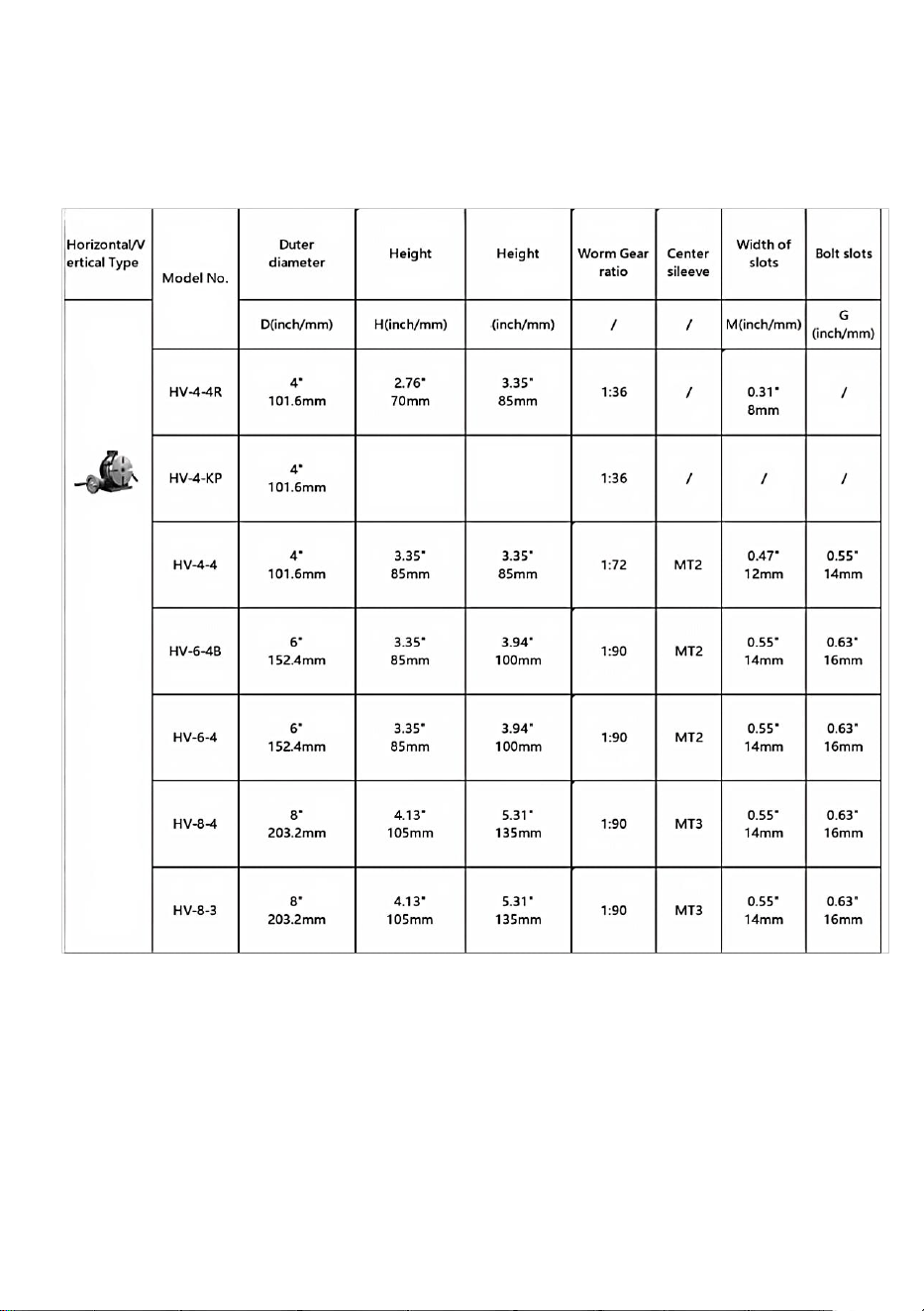
SPECIFICATIONS:
Unit: mm/inches
C
4.72”
120mm
3.35”
85mm
- 4 -
Model
HV-3"
HV-4"
HV-5"
A
98
145
155
B
78
114
127
C
59
85.5
90
D
F76.2
F110
F127
E
12
12
12
G
H
83
85
85
J
15
M
MT2
MT2
N
71
68
68
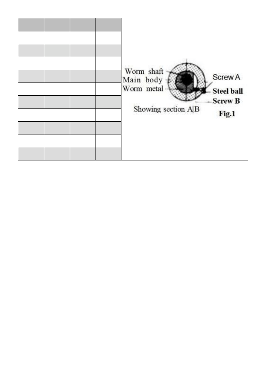
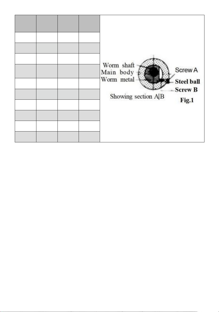
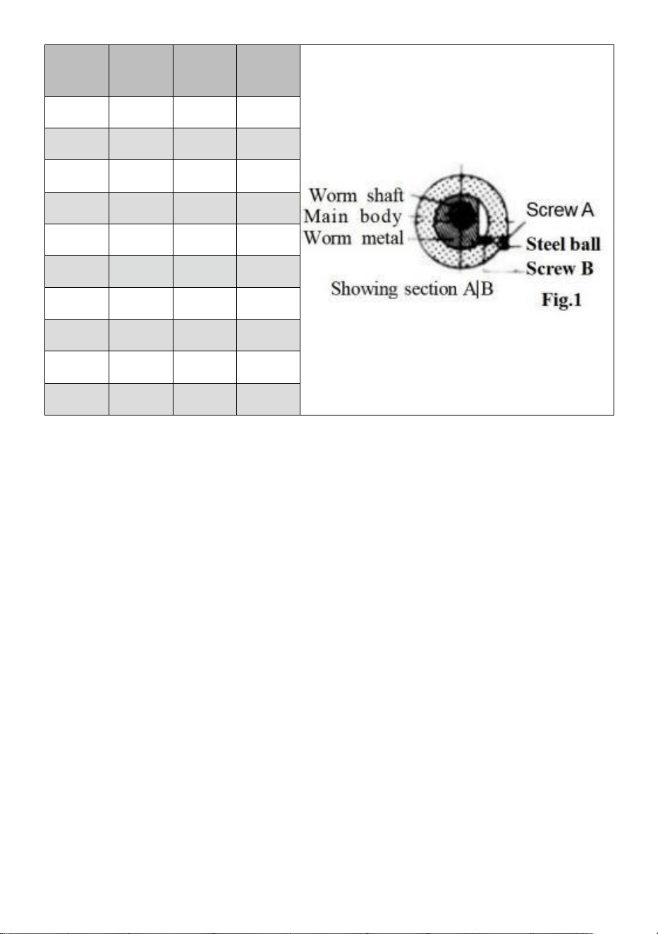
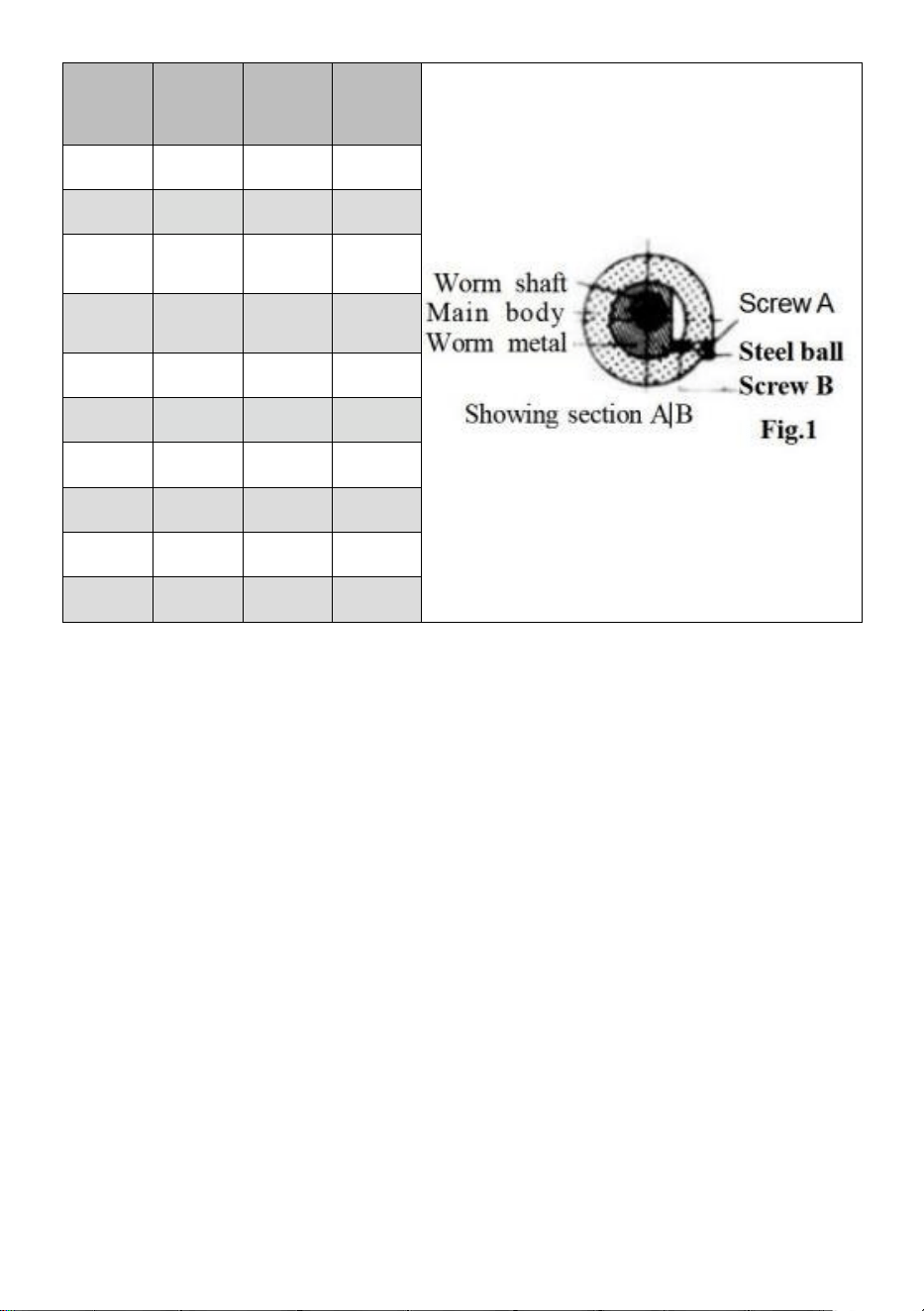
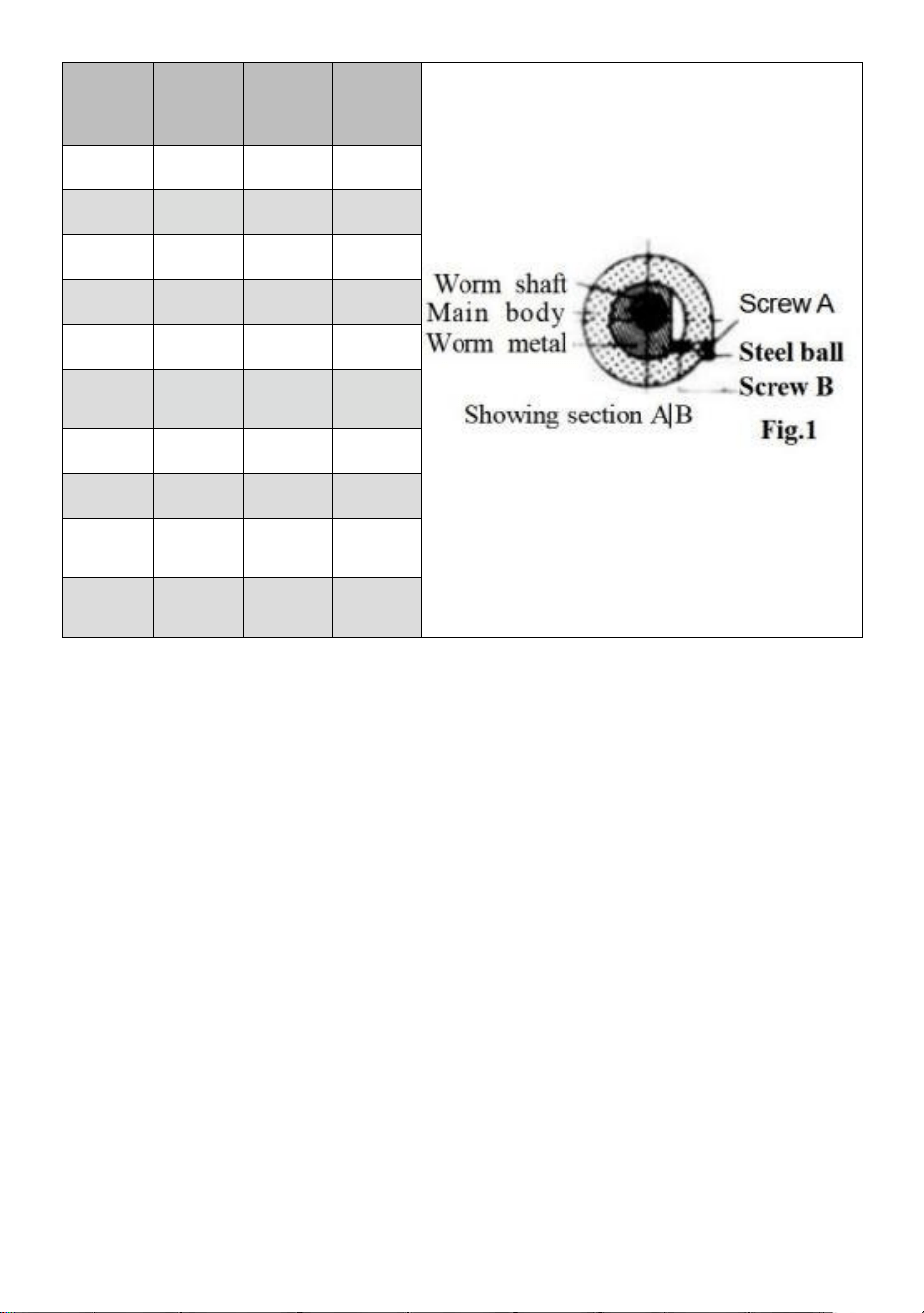
1.Adjusting Mesh of Worm Gear: Loosen the metal clamp handle and
turn the switch metal clockwise until it touches the stopper.The worm
gear has now been disengaged.Turn it counterclockwise until it touches
the stopper, the worm and gear wheel will engage.Tighten the metal
clamp handle after engagement.An additional adjustment can be
obtained by removing the screw ④and steel ball and turning the inner
screw ⑥counterclockwise, so bringing the worm in closer
engagement with the gear wheel.Turning clockwise brings the worm
away from the wheel.After adjustment insert the steel ball and tighten the
screw
④
2.Axial Adjustment of Worm Shaft:When axial slack occurs gear
adjustment is carried out by tightning the inside worm shaft nut after the
handle,vernier ring and switch metal have been removed. After adjustment.
lock the nut on the shaft by means of the set screw. (The ERT-6 has an
adjusting nut,which can be used after removal of the handle.)

- 5 -

- 6 -
Operating Instruction and Function of Each Unit
1.The worm gear ratio is 1:90.
one tum of the handle moves the table by 4°
Micro-collar is graduated in steps of 1 min.
Vernier scale makes settings down to 10 seconds possible.
(20 seconds for (HV6)
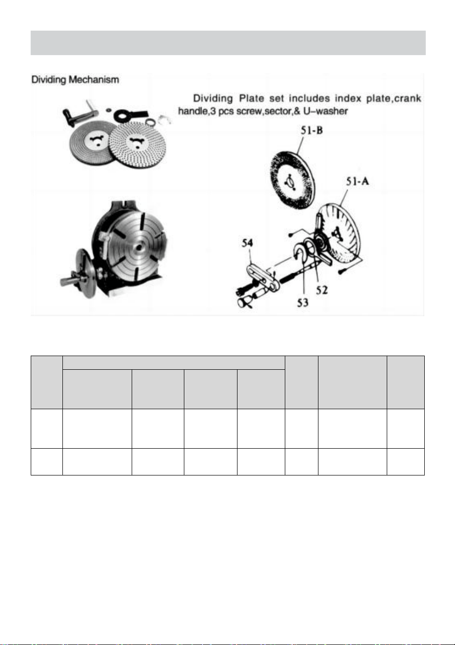
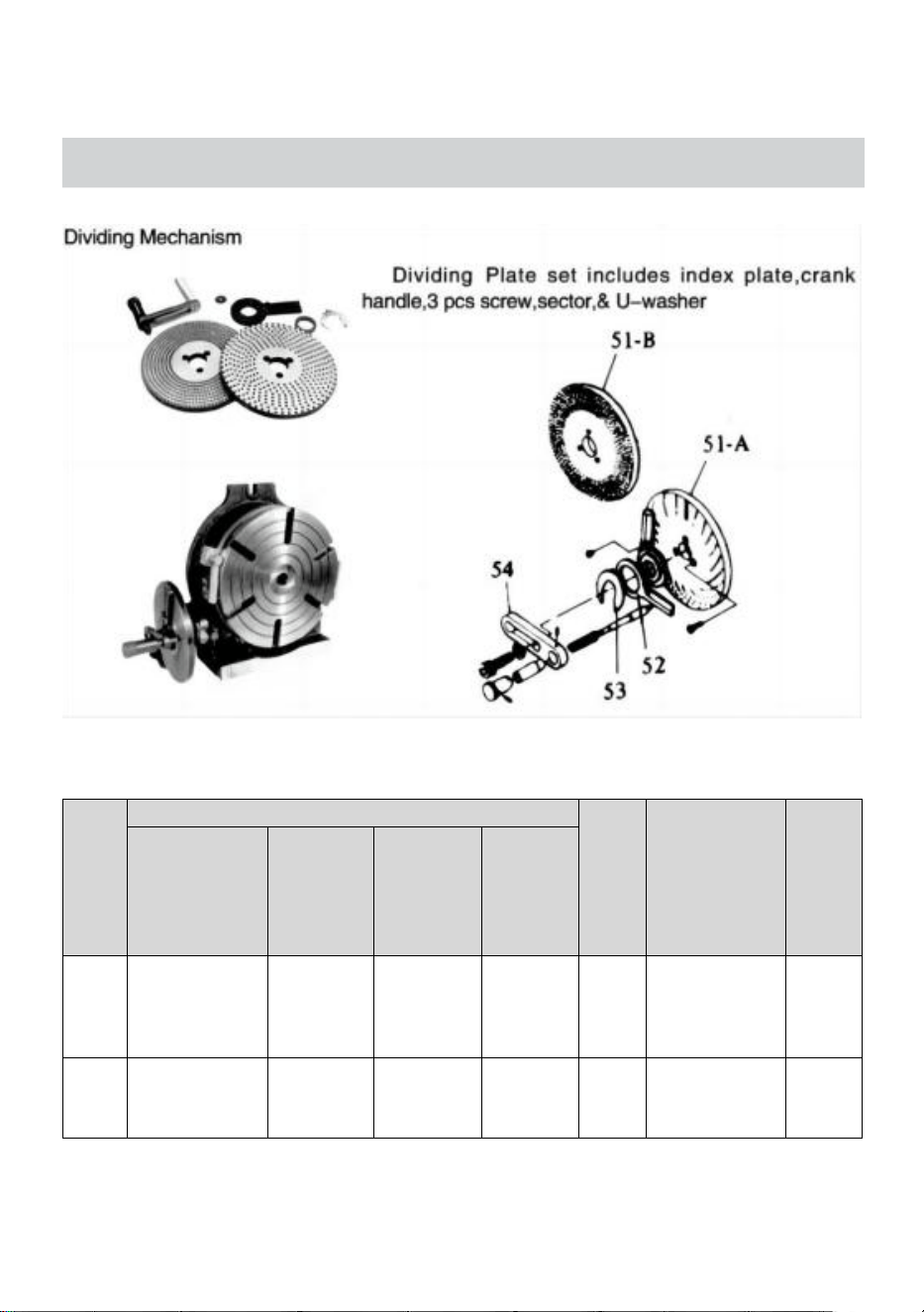
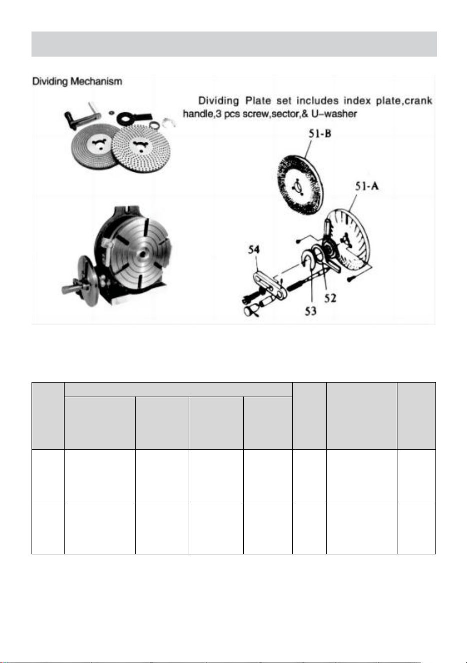
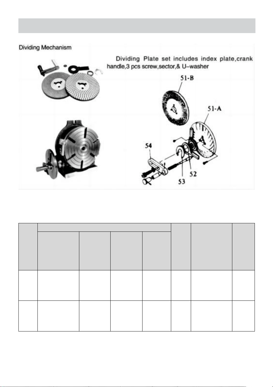
2.Dividing of 2 to 100 can be carried out quickly and accurately
by attaching a Dividing Mechanism.
3.Center work can also be carried out by using the base in the
vertical position in conjunction with a tailstock.(See Page 4.)
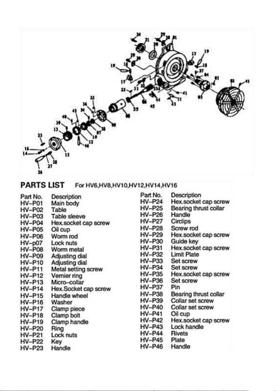
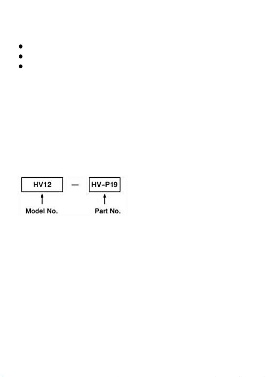
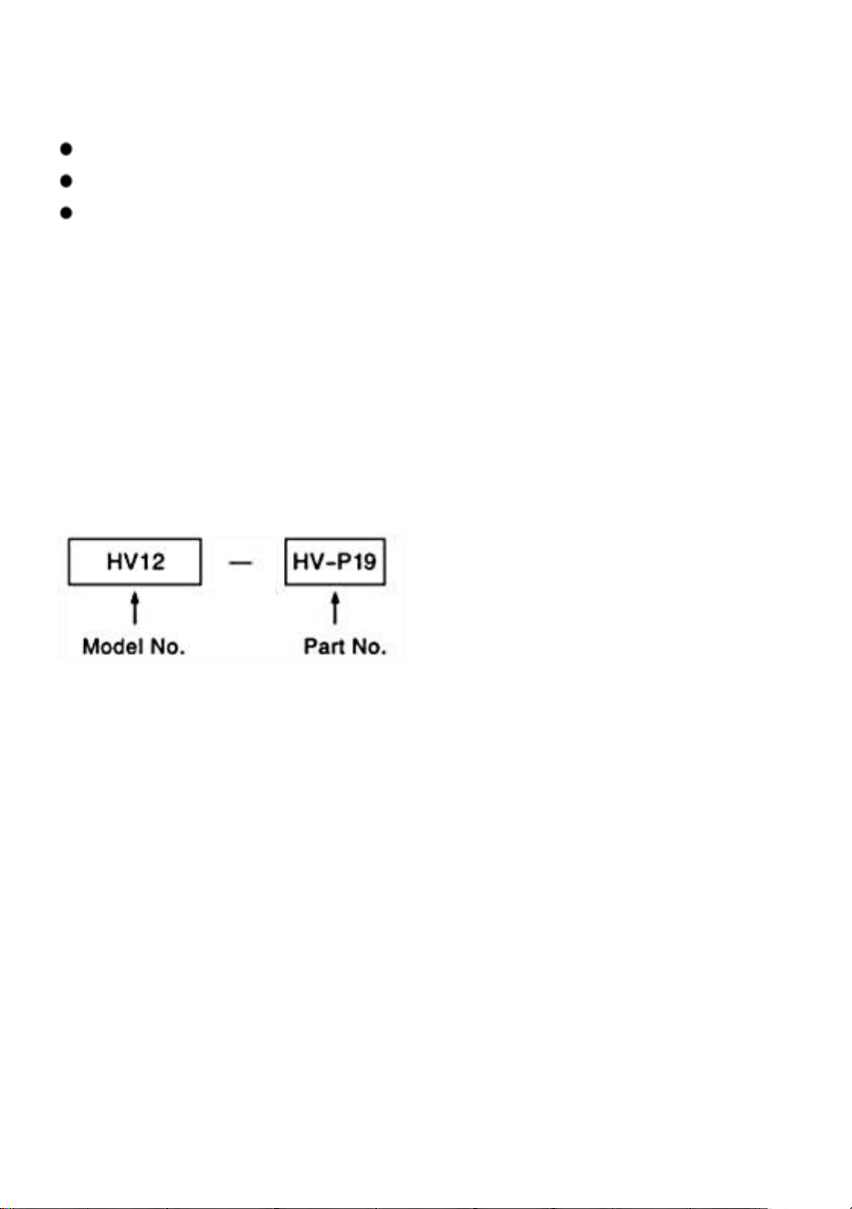
* Suggestions for Order
When ordering parts for replacement,indicate Model No.and Part No.
- 7 -
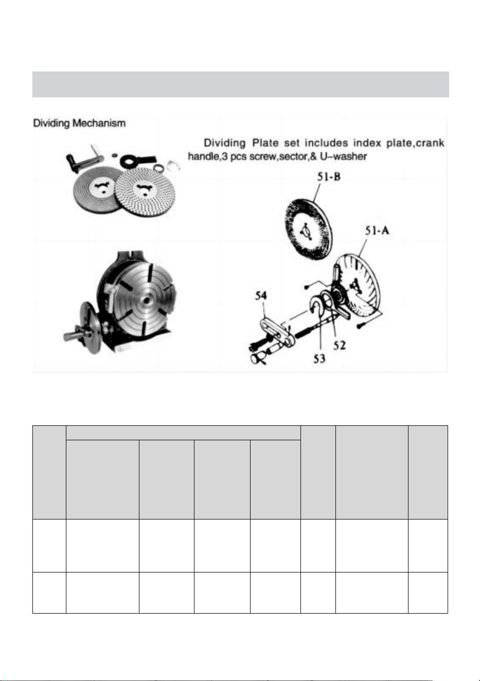
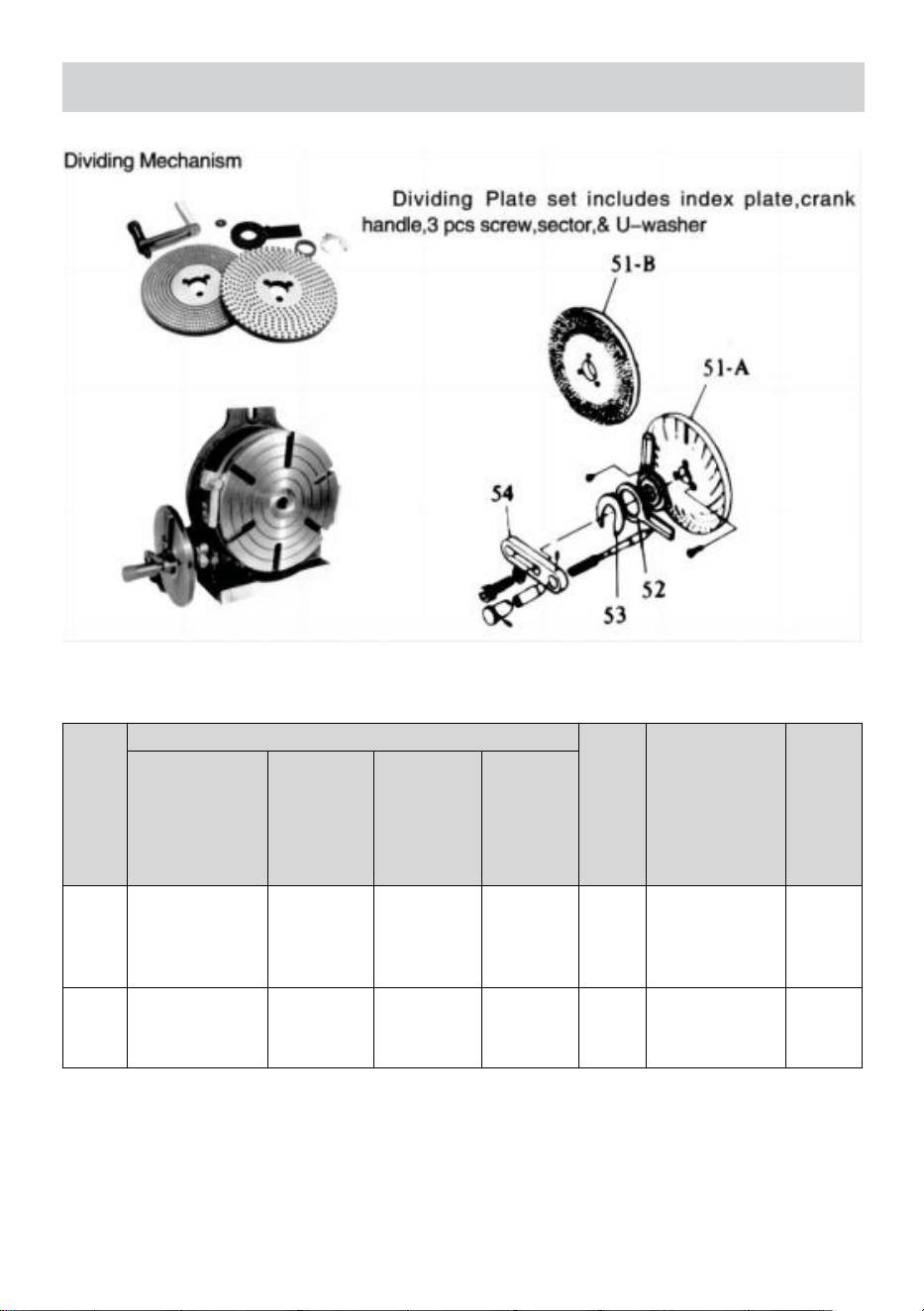
OPTIONAL ACCESSORIES DIVIDING PLATES
RT with Dividing Plate
SPECIFICATIONS FOR DIVIDING PLATES
Unit:mm/inches
MODEL
NO
Major dimension of DM
Weight
kg/Ib
Applicable table
Dividing Plate set
screw
Inner
diameter of
sector am
Outer
diameter of
spring clip
Grove width
in handle
plate
DP-1
PCD.(32/ 1.26)F
21
0.83
18
0.71
9
0.03
25
5.51
MINI
(HV3HV4/HV5)
HV6
P7P9P10
DP-2
(3holes)
PCD.46/1.81
28.7
1.12
44
1.73
10
0.39
4
8.82
HV8,10, 12, 14,16
P7P9P10
- 8 -
In case of An Optional DM Device Attached
Indexing of 2 to 100 can be made accurately and quickly.
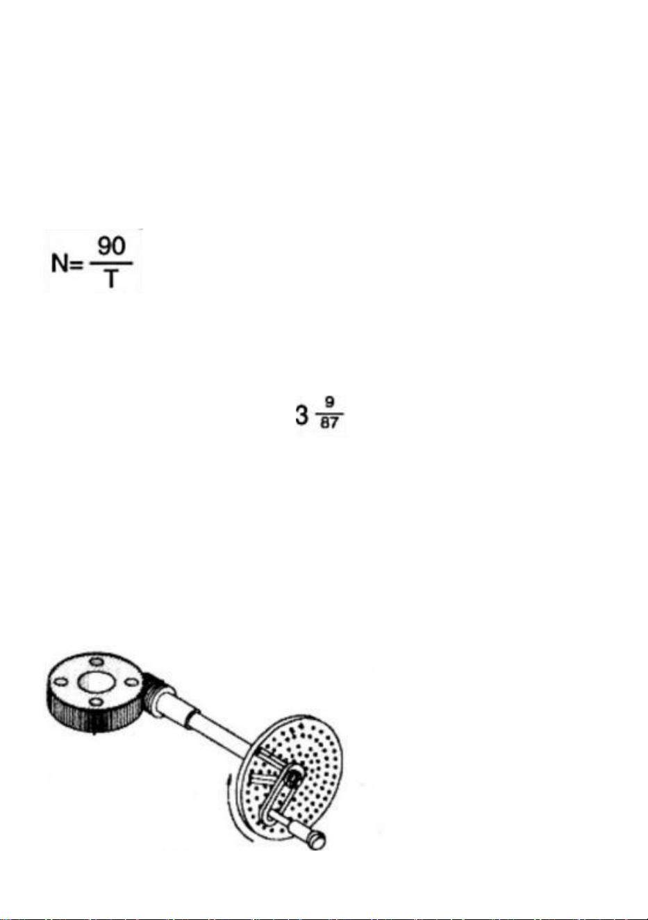
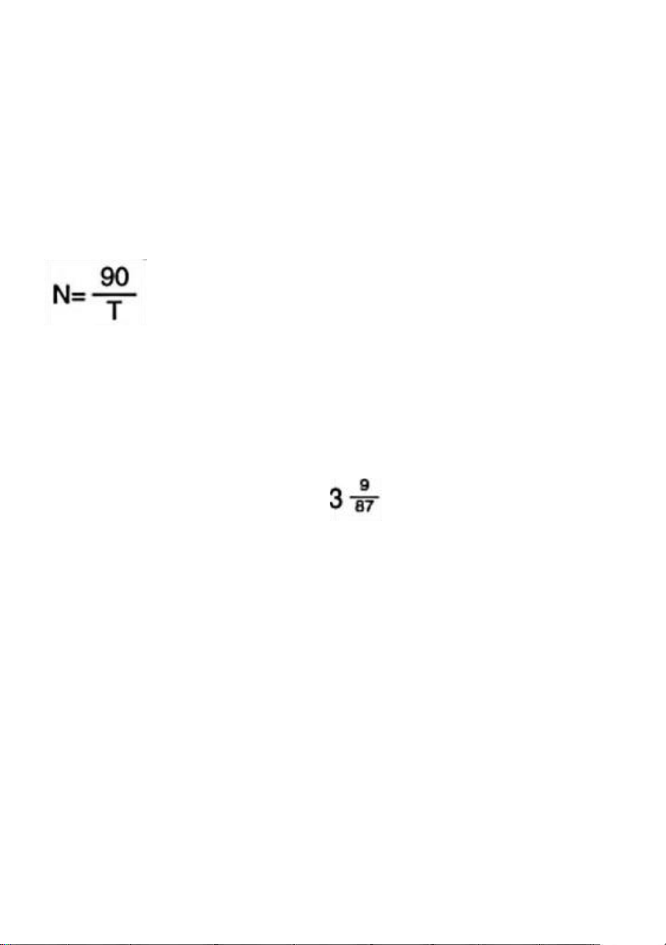
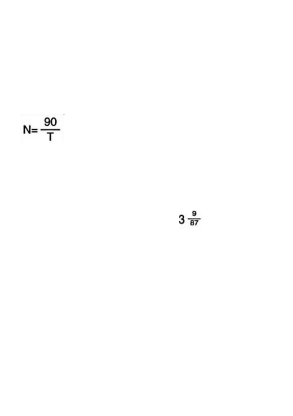
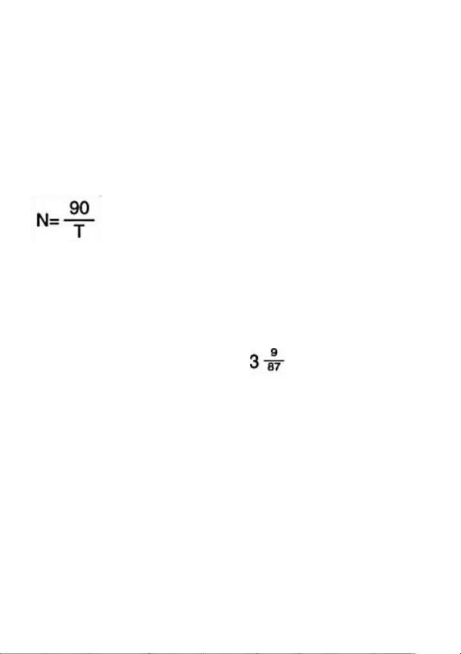
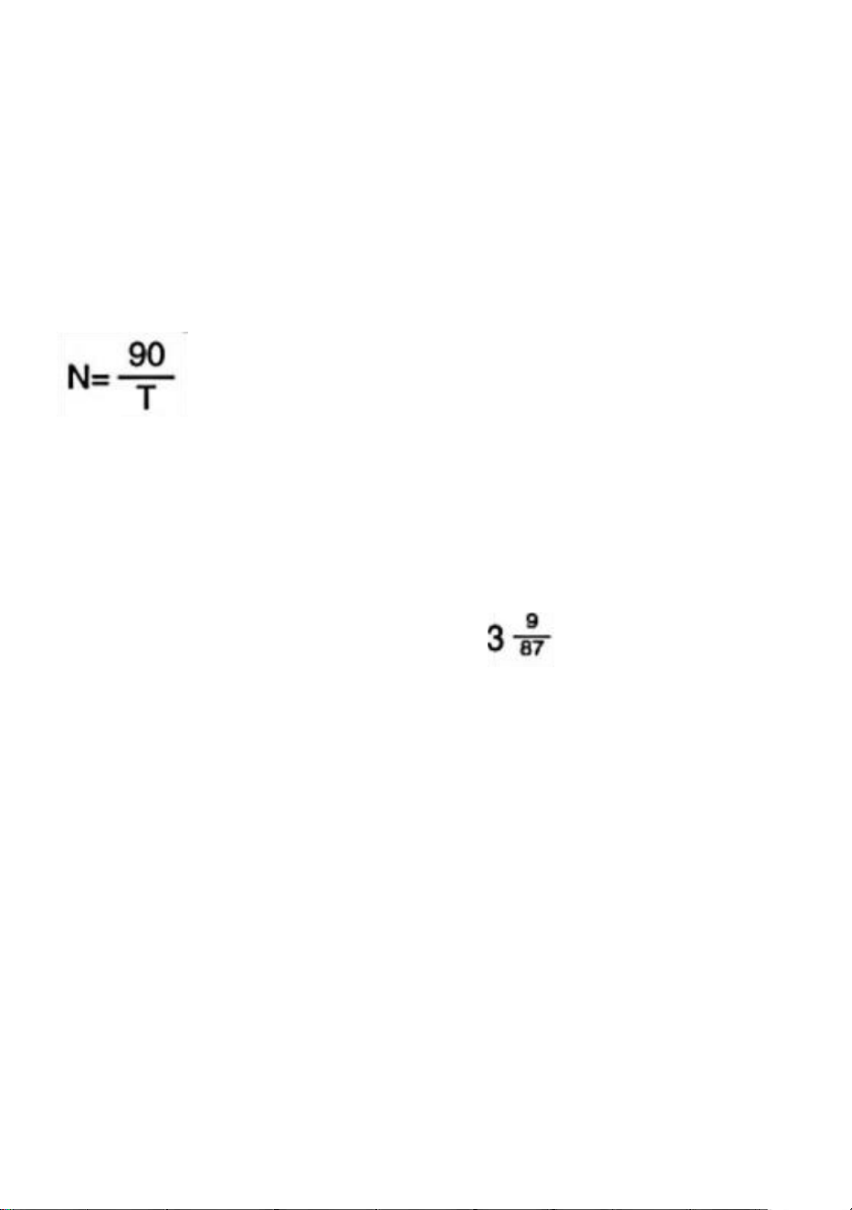
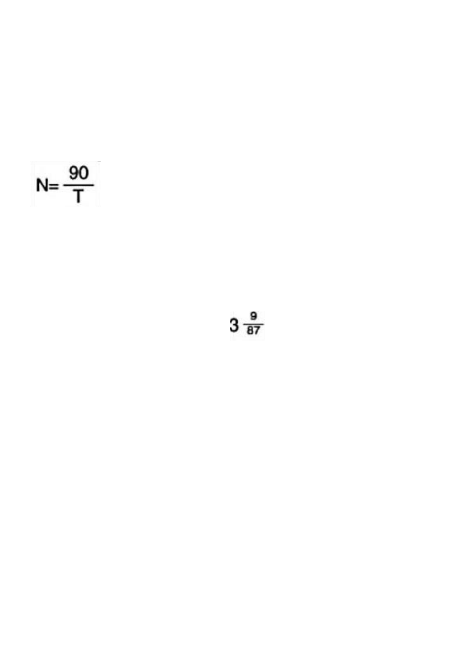
Equation of Indexing
Since the worm ratio is 1:90,when the handle is made to rotate a
360°revolution,the table therefore will rotate a 1/90 revolution.The
relationships between handle revolution 'N' and individual number
'T' to be sought are shown in the following equation:
Remarks:The index table on Page 6 is made on the basis of this equation.
(Example)
In case where the operator wants to index the position divided into 29
equal parts.Hints on operation As for 29 individual numbers, the number
of crank handle revolutions (N)is as shown in the table on Page
6,So that the handle should be rotated a full 360°revolution three times
plus an interval of nine holes (in this time,it means hole intervals not hole
numbers).After setting this point as a start point,rotate the handle a full
360°revolution three times plus an interval of nine holes (in this time,it
means hole intervals not hole numbers).After setting this point as a start
point,rotate the handle a full 360°revolution three times plus an interval of
nine holes.When the procedure is repeated in turn as many as 29 times,the
indexing of dividing into 29 equal parts is thus achieved.

- 9 -
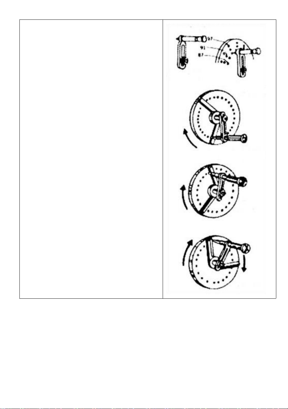
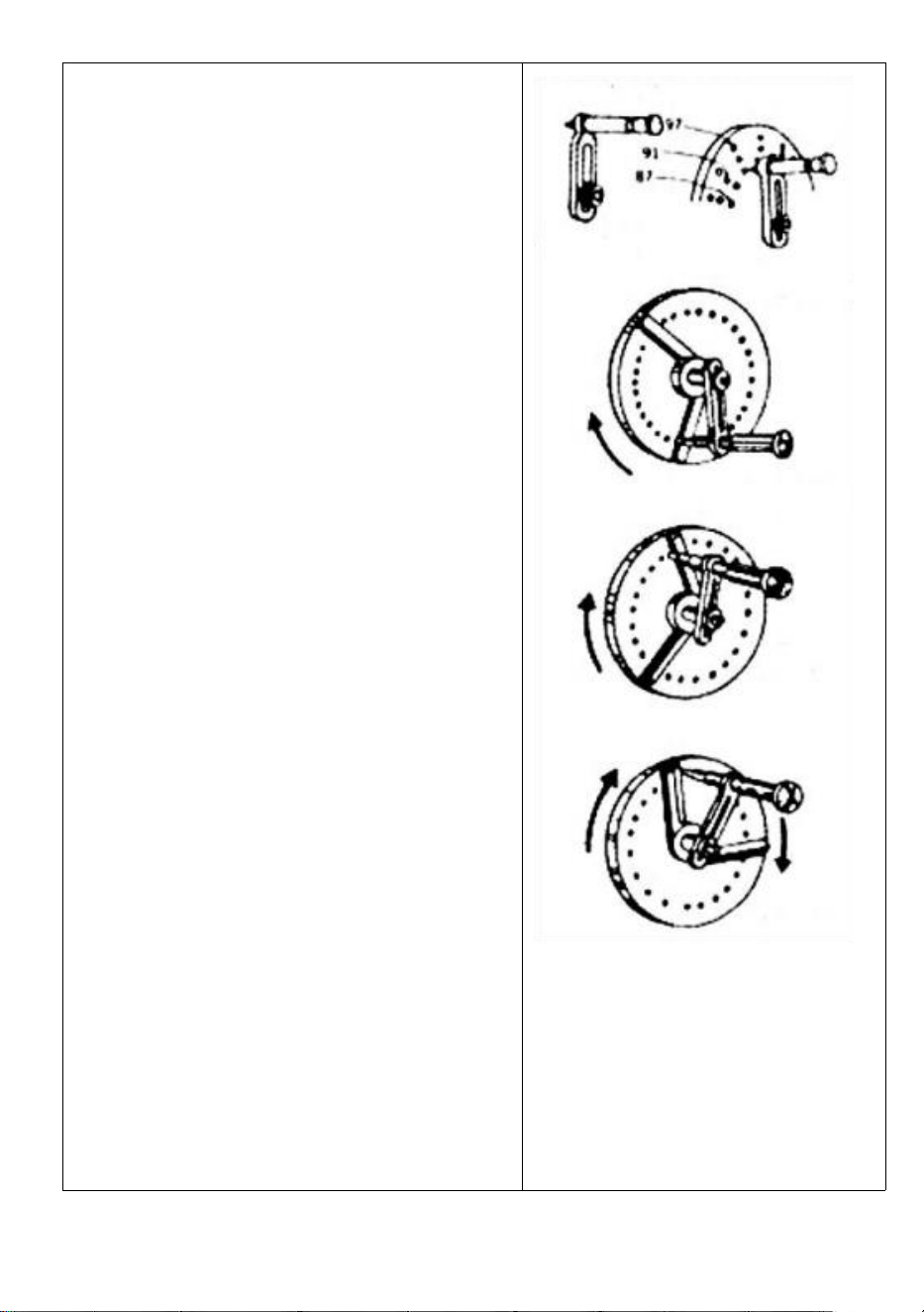
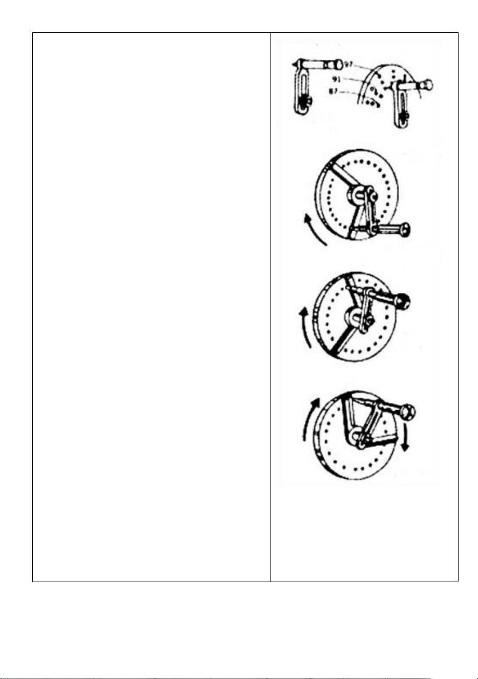
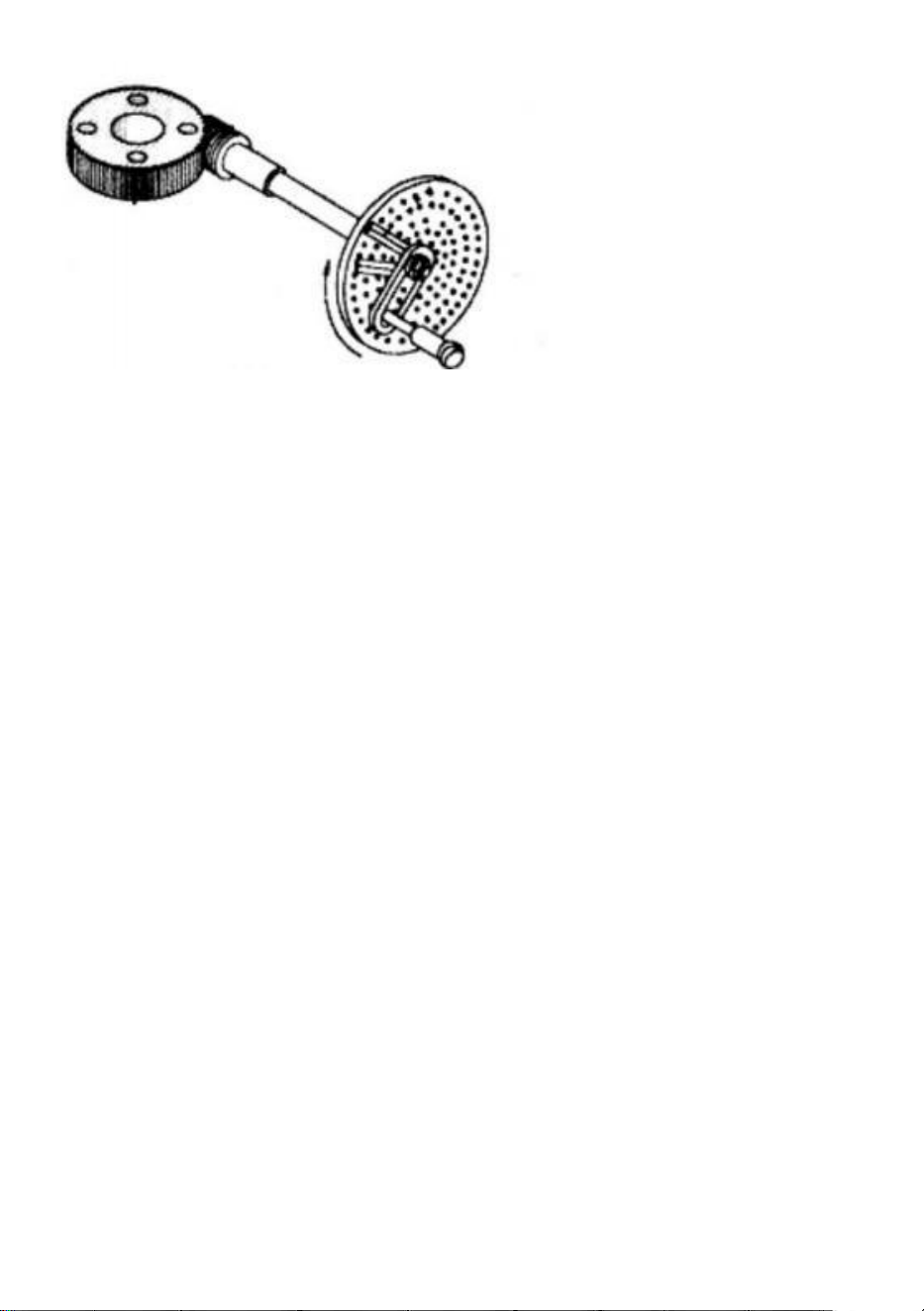
Operations of Crank Handle and Sector
In case of the Example' Division into 29 Equal Parts' aforesaid,it is
natural that indexing operation should proceed with the intervals of nine
holes after setting the index plate (B plate)on which a row of 87 holes
are provided.But in this method,the operator has to count nine holes'
intervals one by one. He must feel inefficient.In this viewpoint,it is
necessary to use a device called 'sector'to avoid such troublesome
procedures.The following will describe some necessary procedures for
operation of the sector.
- 10 -
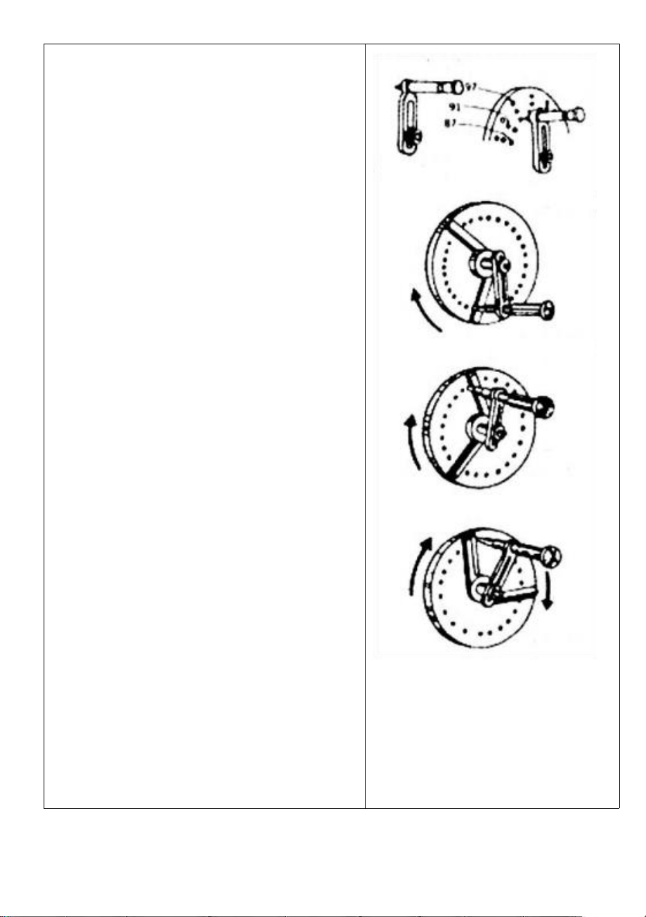
a. Loosen the crank handle lock nut,adjust
its length so as to cause the index pin to fall
in the train of 87 holes,and tighten it.
b. Loosen the set-screws of the sector.open
two arms in accordance with the interval of
nine holes (total numbers of holes is ten),
and tighten with setscrews.
c. First,bring the left arm of the sector near
to the index pin's left side.
d. Next,rotate the crank handle clockwise to
apply it to the right arm of the sector so that
the index pin will fall in the hole located at
this right arm's left side surface.
e. Rotate the sector clockwise this time,and
put the right side surface of the left arm to
the left side of the index pin.In this time,the
relationships between the index pin and the
sector's left arm in their positions are the
same as in Par.c).
The index plate hole that actually
accommodates the index pin is located at
the point where it goes across ten holes to
the right away from the hole as in par.c)c.
f. Repeat the same procedures as
necessary.
Crank handle
Index pen
Fig 5
Fig 6
Fig 7
Fig 8

- 11 -
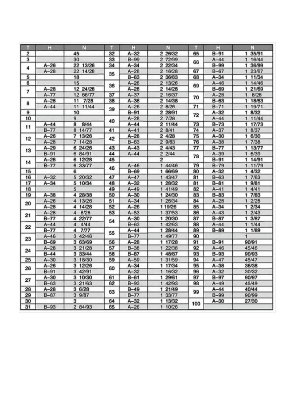
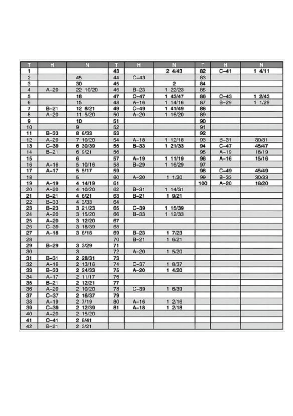
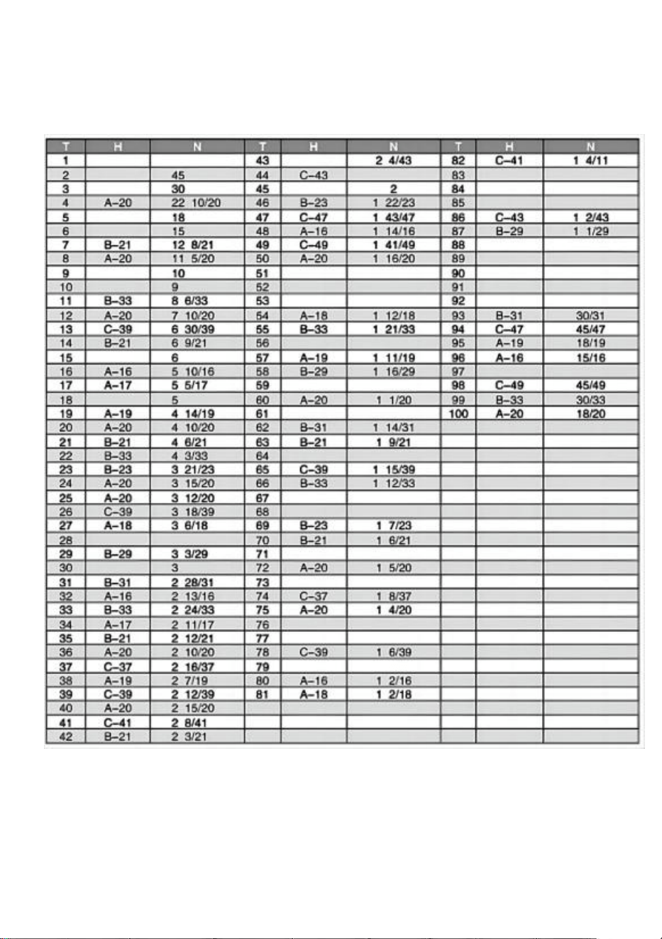
Index Table(For worm ratio 1:90) DP-1 For
HV6/MINI(HV3/HV4/HV5)

- 12 -
DP-2 For HV8,HV10,HV12,HV14,HV16
Description of in the index table.
This table is the one being calculated for the index plate with hole
numbers shown below.
Description of codes used in the index table
T: Desired individual number

PA
- 13 -
N: Number of revolutions of the index plate
:Option
A: Using A plate
B: Using B plate
Number of holes
DP-1
A Plate
15, 16,17, 18,19,20
B Plate
21,23,27,29,31,33
C Plate
DP-2
37,39,41,43,47,49
A Plate
26,28,30,32,34,37,38,39,41,43,44,46,47,49,51,53,57,59
B Plate
61,63,67,69,71,73,77,79,81,83,87,89,91,93,97,99

- 14 -
PARTS LIST
Model HV-4-KP
1. Main body * 1
2. Handle * 2
3. Chuck wrench * 1
4. Reverse jaws * 1 set (3pcs)
5. M10 * 40 T-bolt * 2
6. M10 nut * 2
7. Instructions * 1
Model HV-4-4
1. Main body * 1
2. Handle * 2
3. M6 * 55 bolt * 2
4. M6 nut * 2
5. φ 6 flat gasket * 2
6. Positioning block * 2
7. Pressing plate * 2
8. Cushion block * 2
9. Instructions * 1
10. A partition board * 1
11. B partition board * 1
12. C partition board * 1
13. Rocker handle * 1
14. M8 * 70 hex socket handle screw * 1
15. Division plate positioning regulator * 1
16. Limit block * 1
17. Circlip * 1
18. M5 * 10 Phillips screw * 3

- 15 -
Model HV-4-4R
1. Main body * 1
2. Handle * 2
3. M6 * 55 bolt * 2
4. M6 nut * 2
5. φ 6 flat gasket * 2
6. Positioning block * 2
7. Pressing plate * 2
8. Cushion block * 2
9. Instructions * 1
Model HV-6-4B
1. A partition board * 1
2. B partition board * 1
3. C partition board * 1
4. Rocker handle * 1
5. M8 * 70 hex socket handle screw * 1
6. Division plate positioning regulator * 1
7. Limit block * 1
8. Circlip * 1
9. M5 * 10 Phillips screw * 3
10. M5 * 10 hex socket screw * 4
11. Positioning block * 4
12. M12 * 40 T-bolt * 2
13. Nut * 2
14. Internal hexagonal wrench * 1
15. Instructions * 1

- 16 -
Model HV-6-4
1. Main body * 1
2. Rocker handle * 1
3. M8 * 70 hex socket handle screw * 1
4. M5 * 10 hex socket screw * 4
5. Positioning block * 4
6. M12 * 40 T-bolt * 2,
7. Nut * 2
8. Instructions * 1
Model HV-8-4
1. Main body * 1
2. Handle * 2
3. Nut * 2
4. M10 * 80 hexagonal handle bolt * 1
5. Positioning block * 4
6. M5 * 8 hexagonal socket bolt * 4
7. M14 * 60 T-bolt * 2
8. Internal hexagonal wrench * 1
9. Instructions * 1
Model HV-8-3
1. Main body * 1
2. Handle * 2
3. M10 * 80 hex socket handle screw * 1
4. Positioning block * 4
5. M5 * 8 hexagonal socket bolt * 4
6. M14 * 60 T-bolt * 2
7. Internal hexagonal wrench * 1
8. Nut * 2
9. Instructions * 1
- 17 -
Address: Baoshanqu Shuangchenglu 803long 11hao 1602A-1609shi
Shanghai
Imported to AUS: SIHAO PTY LTD. 1 ROKEVA STREETEASTWOOD
NSW 2122 Australia
Imported to USA: Sanven Technology Ltd. Suite 250. 9166 Anaheim
Place, Rancho Cucamonga, CA 91730
REP
EC
SHUNSHUN GmbH
Römeräcker 9 Z2021, 76351 Linkenheim-
Hochstetten, Germany
REP
UK
Pooledas Group Ltd
Unit 5 Albert Edward House, The
Pavilions Preston, United Kingdom
Made In China


Assistance technique et certificat de garantie électronique
www.vevor.com/support
ROTATIF _ TABLEAU
MODÈLE : HV-4-KP, HV-4-4, HV-4-4R,
HV-6-4, HV-6-4B, HV-8-4 , HV-8-3
We continue to be committed to provide you tools with competitive price.
"Save Half", "Half Price" or any other similar expressions used by us only represents an
estimate of savings you might benefit from buying certain tools with us compared to the
major top brands and does not necessarily mean to cover all categories of tools offered by
us. You are kindly reminded to verify carefully when you are placing an order with us if you
are actually saving half in comparison with the top major brands.

- 1 -
ROTARY TABLE
MODÈLE : HV-4-KP, HV-4-4, HV-4-4R, HV-6-4, HV-6-4B, HV-8-4 HV-8-3
BESOIN AIDE ? CONTACT NOUS !
Avoir produit des questions ? Besoin technique soutien ? S'il te plaît
sentir gratuit contacter nous :
Technique Soutien et E - Garantie Certificat
www . vevor . com / support
Ce est le original instructions, veuillez lire attentivement toutes les
instructions du manuel avant de l'utiliser. VEVOR se réserve une
interprétation claire de notre utilisateur manuel . Le apparence de le le
produit sera soumis au produit toi reçu. Veuillez nous pardonner, nous
ne vous informerons plus s'il y a sont n'importe lequel technologie ou
logiciel mises à jour sur notre produit .
- 2 -
le risque de blessure, l'utilisateur doit lire les
instructions manuel soigneusement .
PRECISION ROTARY TABLES
Deux types de tables rotatives sont résumés ici collectivement . Les
mécanismes commun à ces les tables sont présentés sur certaines
pages de leur description .
HORIZONTAL VERTICAL _ PRÉCISION ROTATIF TABLEAU
Ce rotatif tableau est conçu pour le permettre usinage opérations à un
plus haut dimension supérieure à celle de la table rotative de type
horizontal . La base peut être utilisé dans un position verticale _ à activer
il à porter hors centre travail .
- 3 -
CARACTÉRISTIQUES : _
Unité : mm/pouc
e s
C
4.72”
120mm
3.35”
85mm
- 4 -
Modèle
_
HT - 3"
HT - 4"
HT - 5"
UN
9 8
145
155
B
78
114
127
C
5 9
8 5,5
9 0
D
F7 6.2
_
F110
F 1 27
E
1 2
1 2
1 2
g
H
8 3
8 5
8 5
J.
1 5
M.
MT2 _
MT2 _
N
71
68
68
1.Ajustement Engrener de Ver Engrenage : Desserrer le métal serrer
poignée et tourne _ le changer métal dans le sens des aiguilles d'une
montre jusqu'à il touche le bouchon . Le ver l'équipement a maintenant a
été désengagé . Tourner il dans le sens inverse des aiguilles d'une
montre jusqu'à il touche le bouchon, le ver et engrenage roue volonté
s'engager . Serrer le métal poignée de serrage après fiançailles . Un un
réglage supplémentaire peut être obtenu en supprimant le vis ④ et la
bille d'acier et en tournant la vis intérieure ⑥ dans le sens inverse des
aiguilles d'une montre , rapprochant ainsi la vis sans fin de l'engrenage.
roue . Tournant dans le sens des aiguilles d'une montre apporte le ver
loin de la roue. Après réglage insérer le acier boule et serrez la vis ④
2.Axia l Ajustement de Ver Arbre : Quand axial mou se produit réglage
des vitesses est porté dehors par serrage l'écrou intérieur de l'arbre à vis
sans fin après que la poignée, l'anneau vernier et le métal de l'interrupteur
ont été retirés. Après ajustement . bloquer l'écrou sur l' arbre par moyens
de le ensemble vis . ( Le ERT -6 a un ajustement noix , qui peut être
utilisé après le retrait de la poignée.)
- 5 -
- 6 -
En fonctionnement Instruction et Fonction de Chaque Unité
1. Le Le rapport d'engrenage à vis sans fin est de 1:90.
un tour de le poignée se déplace le tableau par 4 °
Micro - collier est diplômé dans pas de 1 mn .
Vernier échelle fait du paramètres vers le bas à 10
secondes possible . (20 secondes ds pour ( HT 6)
2. Diviser de 2 à 100 peut être effectué rapidement et avec
précision en attachant un Partage Mécanisme .
3. Centre travail peut aussi être porté dehors en utilisant la base en
position verticale en conjonction avec une contre-pointe. (Voir page
4.)
* Suggestions pour Commande
Quand commande les pièces pour remplacement , indiquer Modèle Non .
et Partie Non .
- 7 -
OPTIONAL ACCESSORIES DIVIDING PLATES
RT avec Diviser _ Plaque
CARACTÉRISTIQUES _ POUR PARTAGE
PLAQUES
U nit : mm / pouces
MODÈL
E _
NON
_
Dimensions majeures de DM
Poids
kg /
Ib _
En vigueur
tableau
Plaque de
séparation
vis de
réglage
Intérieur
diamètre de
secteur
suis
extérieu
r du
ressort
agrafe
Largeur du
bosquet
dans la
poignée
plaque
_
DP -
1
PCD.(32/ 1.26) F
2 1
0. 83
1 8
0. 71
9
0. 03
2 5
5. 51
MINI
( HV3HV4 / HV5
)
HV6
P7P9P10
_ _ _ _ _
DP -2
( 3 trous)
PCD .
46/1,81
28.7 _
1.12
44
1,73 _
dix _
0. 39
4
8. 82
HV8,10, 12, 14,16
P7P9P10
_ _ _ _ _
- 8 -
Dans cas de Un Facultatif DM Appareil _ Ci-joint
Indexage de 2 à 100 canettes être fait avec précision et rapidement.
Équation de Indexation _
Depuis le ver rapport est de 1:90, lorsque l'on fait tourner la
poignée sur un tour de 360° , le tableau donc volonté faire un
tour de 1/90. Les relations entre poignée révolution ' N ' et
numéro individuel ' T ' à être recherché sont montré dans
l'équation suivante :
Remarques : Le Le tableau d’indexation de la page 6 est réalisé sur la
base de cette équation.
( Exemple )
Dans le cas où le opérateur veut à indice le position divisé en 29 égaux
les pièces . Astuces sur opération Comme pour 29 personnes les
chiffres , les nombre
de manivelle poignée tours ( N ) est comme montré dans le
tableau sur Page
6, donc que le poignée doit être tourné sur un tour complet de 360° trois
fois et plus un intervalle de neuf trous ( dans ce temps , cela signifie les
intervalles de trous et non les numéros de trous ). Après paramètre ce
indiquer comme un commencer point , faites pivoter la poignée d'un tour
complet de 360° trois fois plus un intervalle de neuf trous ( dans ce le
temps , ça veut dire trou intervalles pas trou Nombres ). Après avoir défini
ce point comme point de départ , faites pivoter la poignée fait un tour
complet de 360° trois fois plus un intervalle de neuf des trous . Quand le
procédure est répété à son tour jusqu'à 29 fois, l' indexation de partage en
29 parties égales est ainsi réalisé.

- 9 -

- 10 -
Opérations _ de Manivelle Poignée et Secteur
Au cas où de le Exemple ' Division en 29 Égal Pièces ' susvisées , il est
il est naturel que l'opération d'indexation se poursuive avec le intervalles
de neuf des trous après réglage le indice plaque ( B plaque ) sur lequel
un rangée de 87 trous sont prévus . Mais dans cette méthode,
l'opérateur doit compter les intervalles de neuf trous un par un . Il doit se
sentir inefficace. De ce point de vue, il est nécessaire d'utiliser un
dispositif appelé « secteur » pour éviter l'identification tel gênant
procédures . Le suivant sera décrire quelques procédures nécessaires
au fonctionnement du secteur.
- 11 -
un . Desserrer le manivelle poignée
verrouillage écrou , ajustez son longueur
donc comme à cause le indice épingle à
tomber dedans le former de 87 trous , et
serrer il .
b . Desserrer le ensemble - vis de le secteur
. ouvrir deux bras dans conformité avec le
intervalle de neuf trous ( total Nombres de
des trous est dix ) , et serrer avec vis de
réglage .
c . Tout d'abord , apportez le gauche bras
de le secteur près de le indice des épingles
_ gauche côté .
d . Ensuite , faites pivoter le manivelle
poignée dans le sens des aiguilles d'une
montre postuler il à le droite bras de le
secteur donc que le indice épingle volonté
automne dans le trou situé à ceci droite bras
_ _ gauche côté surface .
e . Tourner le secteur dans le sens des
aiguilles d'une montre ce temps , et mettre le
droite côté surface de le gauche bras au
gauche côté de le indice épingle . Dans ce
le temps , les relations entre le indice
épingle et le secteur _ gauche bras dans
leur postes sont le même comme dans Par .
c ).
Le indice plaque trou que accueille
réellement le indice épingle est situé au
indiquer où il va à travers dix des trous au
droite loin depuis le trou comme dans par .
c ) c . F . Répéter le même procédures le
cas échéant .
Manivelle _
Indice stylo
figue 5
figue 6
F ig 7
figue 8

- 12 -
Indice Tableau ( Pour ver rapport 1 : 90) DP-1 Pour
HV6/MINI(HV3/HV4/HV5)

- 13 -
DP -2 Pour HT 8, HT 10, HT 12, HT 14, HT 1 6
Description de dans le indice tableau.
Ce tableau est le un être calculé pour le indice plaque avec trou
numéros affichés ci-dessous .
Description _ de codes utilisé dans le indice tableau
T : Numéro individuel souhaité

Pennsylvani e
- 14 -
N : Nombre de révolutions de le indice plaque
: Option _
UN : En utilisant UN plaque
B : En utilisant B plaque
Nombre de des trous
DP - 1
Une
assiette
15 , 16,17, 18,19,20
B Plaque
21,23,2 7,29,31,33
CP en
retard
DP - 2
37,39,41,4 3,47,49
Une
assiette
26,28,
30,32,34,37,38,39,41,43,44,46,47,49,51,53,57,59
B Plaque
61,63,6 7,69,71,73,77,79,81,83,87,89,91,93,97,99

- 15 -
LISTE DES PIECES
Modèle HV-4-KP
1. Principal corps * 1
2. Poignée * 2
3. Mandrin clé * 1
4. Inverse _ mâchoires * 1 ensemble (3 pièces )
5. M10 _ * 40 Boulon en T * 2
6. M10 noix * 2
7. Instructions * 1
Modèle HV-4-4
1. Principal corps * 1
2. Poignée * 2
3. M6 * 55 boulon * 2
4. M6 noix _ * 2
5. φ 6 plat joint * 2
6. Positionnement _ bloc * 2
7. Pressage plaque _ * 2
8 . Coussin bloc * 2
9. Instructions * 1
dix . UN cloison conseil * 1
11 . B cloison conseil * 1
12 . C cloison conseil * 1
13 . Bascule poignée * 1
14 . M8 _ * 70 hexadécimal prise poignée vis * 1
15 . Division plaque positionnement régulateur * 1
16 . Limite bloc * 1
17 . Circlips * 1
18 . M5 * dix Phillips vis * 3

- 16 -
Modèle HV-4-4R
1. Principal corps * 1
2. Poignée * 2
3. M6 * 55 boulon * 2
4. M6 noix _ * 2
5. φ 6 plat joint * 2
6. Positionnement _ bloc * 2
7. Pressage plaque _ * 2
8 . Coussin bloc * 2
9. Instructions * 1
Modèle HV-6-4B
1 . UN cloison conseil * 1
2. B cloison conseil * 1
3 . C cloison conseil * 1
4 . Bascule poignée * 1
5. M8 _ * 70 hexadécimal prise poignée vis * 1
6. Division plaque positionnement régulateur * 1
7. Limite bloc * 1
8 . Circlips * 1
9. M5 * dix Phillips vis * 3
dix. M5 _ * dix hexadécimal prise vis * 4
11. Positionnement _ bloc * 4
12. M12 _ * 40 Boulon en T * 2
13 . Noix * 2
14. Interne hexagonal clé * 1
1 5. Instructions * 1

- 17 -
Modèle HV-6-4
1. Principal corps * 1
2. Bascule poignée * 1
3. M8 _ * 7 0 hexadécimal prise poignée vis * 1
4 . M5 * dix hexadécimal prise vis * 4
5. Positionnement bloc * 4
6. M12 * 40 Boulon en T * 2,
7. Noix * 2
8 . Instructions * 1
Modèle HV-8-4
1. Principal corps * 1
2 . Poignée * 2
3. Noix * 2
4. M10 _ * 80 hexagonal poignée boulon * 1
5. Positionnement bloc * 4
6. M5 _ * 8 hexagonal prise boulon * 4
7. M14 _ * 60 Boulon en T * 2
8. Interne hexagonal clé * 1
9. Instructions * 1
Modèle HV-8-3
1. Principal corps * 1
2. Poignée * 2
3. M 1 0 * 80 hexadécimal prise poignée vis * 1
4. Positionnement _ bloc * 4
5. M5 * 8 h hexagonal prise boulon * 4
6. M14 _ * 60 Boulon en T * 2
7. Interne hexagonal clé * 1
8. Noix * 2
9. Instructions * 1

- 18 -
Adresse : Baoshanqu Shuangchenglu 803long 11hao 1602A-1609shi
Shanghai
Importé en Australie : SIHAO PTY LTD . 1 ROKEVA
STREETASTWOOD NSW 2122 Australie
Importé aux États-Unis : Sanven Technology Ltd. Suite 250 . 9166
Anaheim Place, Rancho Cucamonga, Californie 91730
REP
EC
SHUNSHUN GmbH
Römeräcker 9 Z2021, 76351 Linkenheim-
Hochstetten, Germany
REP
UK
Pooledas Group Ltd
Unit 5 Albert Edward House, The
Pavilions Preston, United Kingdom
Fabriqué en Chine


Zertifikat für technischen Support und E-Garantie
www.vevor.com/support
R OTARY TISCH
MODELL : HV-4-KP, HV-4-4, HV-4-4R,
HV-6-4, HV-6-4B, HV-8-4 , HV-8-3
We continue to be committed to provide you tools with competitive price.
"Save Half", "Half Price" or any other similar expressions used by us only represents an
estimate of savings you might benefit from buying certain tools with us compared to the
major top brands and does not necessarily mean to cover all categories of tools offered by
us. You are kindly reminded to verify carefully when you are placing an order with us if you
are actually saving half in comparison with the top major brands.

- 1 -
ROTARY TABLE
MODELL : HV-4-KP, HV-4-4, HV-4-4R, HV-6-4, HV-6-4B, HV-8-4 HV-8-3
BRAUCHEN HELFEN ? KONTAKT UNS !
Haben Produkt Fragen ? Brauchen technisch Unterstützung ? Bitte
fühlen frei in Verbindung zu treten uns :
Technisch Unterstützung Und E – Garantie
Zertifikat www . vevor . com /
Support
Das Ist Die Original Bitte lesen Sie alle Bedienungsanleitungen
sorgfältig durch, bevor Sie mit der Inbetriebnahme beginnen. VEVOR
behält sich eine klare Interpretation unseres Nutzers vor Handbuch . Der
Aussehen von Die Das Produkt unterliegt dem Produkt Du erhalten.
Bitte entschuldigen Sie, dass wir Sie in diesem Fall nicht noch einmal
informieren werden Sind beliebig Technologie oder Software

- 2 -
Aktualisierung An unser Produkt .
- 3 -
Warnung: Um das Verletzungsrisiko zu verringern,
muss der Benutzer die Anweisungen lesen
Handbuch sorgfältig .
PRECISION ROTARY TABLES
Es werden zwei Arten von Rundtischen zusammengefasst Hier
kollektiv . Die Mechanismen gemeinsam Zu diese Tische werden auf
einigen Seiten ihrer Beschreibung angezeigt .
HORIZONTAL , VERTIKAL PRÄZISION ROTIEREND TISCH
Das rotierend Tisch Ist entworfen, um es dauerhaft zu machen
Bearbeitung Operationen bei ein höheres Abmessungen als die des
horizontalen Drehtisches . Die Basis kann Sei gebraucht In A vertikale
Position _ Zu aktivieren Es Zu tragen aus der Mitte arbeiten .

- 4 -
SPEZIFIKATIONEN : _
Einheit: mm/Zoll
s
C
4.72”
120mm
3.35”
85mm
- 5 -
Modell
_
HV - 3"
HV - 4"
HV - 5"
A
9 8
145
155
B
78
114
127
C
5 9
8 5.5
9 0
D
F 7 6.2
F110
F 1 27
E
1 2
1 2
1 2
G
H
8 3
8 5
8 5
J
15 _
M
MT 2
MT 2
N
71
68
68
1.Einstellen Gittergewebe von Wurm Gang : Lösen Die Metall Klemme
handhaben und umdrehen _ Die schalten Metall im Uhrzeigersinn bis Es
Berührungen Die Stopper . Der Wurm Gang hat Jetzt gewesen
ausgerückt . Drehen Es gegen den Uhrzeigersinn bis Es Berührungen
der Stopfen, der Wurm Und Gang Rad Wille engagieren . Spannen Die
Metall Klemmgriff nach Engagement . Ein Eine zusätzliche Anpassung
kann durch Entfernen erreicht werden Die Schraube ④ und Stahlkugel
entfernen und die innere Schraube ⑥ gegen den Uhrzeigersinn drehen ,
um die Schnecke enger mit dem Zahnrad in Eingriff zu bringen Rad .
Drehen im Uhrzeigersinn bringt Die Wurm vom Rad weg. Nach der
Einstellung einfügen Die Stahl Kugel abziehen und Schraube ④
festziehen
2.Axia l Einstellung von Wurm Welle : Wann axial locker tritt ein
Gangverstellung Ist getragen aus von Straffung die innere
Schneckenwellenmutter, nachdem Griff, Noniusring und Schaltermetall
entfernt wurden. Nach der Einstellung . Kontern Sie die Mutter auf der
Welle von bedeutet von Die Satz schrauben . ( Der ERT -6 hat eine

- 6 -
Anpassung Nuss , die dürfen Sei nach Entfernen des Griffs verwendet
werden.)

- 7 -

- 8 -
Betriebs _ Anweisung Und Funktion von Jede Einheit
1. Die Das Schneckenübersetzungsverhältnis beträgt 1:90.
eins tum von Die handhaben bewegt sich Die Tisch um 4 °
Mikrokragen _ _ Ist graduiert In Schritte von 1 Minute .
Vernier Skala macht Einstellungen runter auf 10
Sekunden möglich . (20 Sekunden ds für ( HV 6)
2. Teilen von 2 bis 100 können durch Anbringen schnell und
präzise durchgeführt werden A Teilen Mechanismus .
3. Mitte arbeiten dürfen Auch Sei getragen aus indem Sie die Basis
in vertikaler Position verwenden in Verbindung mit einem Reitstock.
(Siehe Seite 4.)
* Vorschläge für Befehl
Wann Bestellung Teile für Ersatz , angeben Modell NEIN . Und Teil NEIN .
- 9 -
OPTIONAL ACCESSORIES DIVIDING PLATES
RT mit Dividieren _ Platte
SPEZIFIKATIONEN _ FÜR TEILEN PLATTEN
Einheit : mm / Zoll _
MODEL
L _
NEIN
_
Hauptdimension _ von DM
Gewic
ht
acht
kg /
Ib
Anwendbar
Tisch
Trennplatte e
Stellschrau
be _
Innere
Durchmess
er von
Sektor Bin
Außend
urchmesse
r der Feder
Clip
Hainbreite _
im Griff
Platte _
DP -
1
PKD.(32/ 1,26) F
2 1
0,83 _
1 8
0. 71
9
0. 03
2 5
5. 51
MINI
(HV3H V 4/ HV
5)
HV6
S. 7 S. 9
S. 10
DP -2
( 3Loch)
PCD .
46/1,81
28. 7
1.12
44
1,73 _
1 0
0,39 _
4
8. 82
HV8,10, 12, 14,16
S. 7 S. 9
S. 10
- 10 -
In Fall von Ein Optional DM Gerät _ Beigefügt
Indizierung von 2 bis 100 Dosen Sei gemacht genau und schnell.
Gleichung von Indexing _
Seit Die Wurm Verhältnis beträgt 1:90, wenn der Griff um 360°
gedreht wird Tisch daher Wille Drehen Sie eine 1/90-Umdrehung.
Die Beziehungen zwischen handhaben Revolution ' N ' und
Einzelzahl ' T ' zu Sei gesucht Sind gezeigt in der folgenden
Gleichung:
Bemerkungen : Die Die Indextabelle auf Seite 6 basiert auf dieser
Gleichung.
( Beispiel )
Für den Fall , dass Die Operator will Zu Index Die Position geteilt in 29
gleich Teile . Hinweise An Betrieb Als für 29 Personen Zahlen , die
Nummer
von Kurbel handhaben Umdrehungen ( N ) ist als gezeigt In
Die Tisch An Seite
6, Also Das Die handhaben sollte dreimal und mehr als eine volle 360°-
Umdrehung gedreht werden ein Intervall von neun Löcher ( in Das Zeit ,
es bedeutet Lochintervalle, nicht Lochnummern ). Nach Einstellung Das
Punkt als A Start Drehen Sie den Griff um 360 ° drei mal Plus ein Intervall
von neun Löcher ( in Das Zeit , das heißt Loch Intervalle nicht Loch
Zahlen ). Nachdem Sie diesen Punkt als Startpunkt festgelegt haben ,
drehen Sie ihn Führen Sie den Griff dreimal um eine volle 360°-
Umdrehung plus neun Mal durch Löcher . Wann Die Verfahren Ist Die
Indizierung wird der Reihe nach bis zu 29 Mal wiederholt von teilen Auf
diese Weise wird eine Aufteilung in 29 gleiche Teile erreicht.

- 11 -

- 12 -
Operationen _ von Kurbel Handhaben Und Sektor
Falls _ von Die Beispiel ' Division in 29 Gleich Teile ' vorgenannten , es
Ist Es ist natürlich , dass der Indexierungsvorgang fortgesetzt wird mit
Die Intervalle von neun Löcher nach dem Einstellen Die Index Platte ( B
Platte ) auf welche A Reihe von 87 Löchern werden zur Verfügung
gestellt . Aber Bei dieser Methode muss der Bediener die Intervalle von
neun Löchern eins zählen von eins . Er muss sich ineffizient anfühlen.
Aus dieser Sicht ist es notwendig, ein Gerät namens „Sektor“ zu
verwenden, um ID zu vermeiden solch lästig Verfahren . Der folgenden
Willen beschreiben manche notwendige Verfahren für den Betrieb des
Sektors.

- 13 -
A . Lösen Die Kurbel handhaben sperren
Mutter , stellen Sie sie ein Länge Also als Zu
Ursache Die Index Stift Zu reinfallen Die
Zug von 87 Löchern und _ spannen Es .
B . Lösen Die Set - Schrauben von Die
Sektor . öffne zwei Waffen In
Übereinstimmung mit Die Intervall von neun
Löcher ( insgesamt Zahlen von Löcher Ist
zehn ) und _ spannen mit Stellschrauben .
C . Zuerst mitbringen _ Die links Arm von
Die Sektor in der Nähe von Die Index Stift _
_ links Seite .
D . Als nächstes drehen Die Kurbel
handhaben im Uhrzeigersinn bewerben Es
Zu Die Rechts Arm von Die Sektor Also
dass die Index Stift Wille fallen In Die Loch
gelegen bei diesem Rechts Waffen _ _ links
Seite Oberfläche .
e . Drehen Die Sektor im Uhrzeigersinn
Das Zeit , und setzen Die Rechts Seite
Oberfläche von Die links Arm zum links
Seite von Die Index Stift . In Das Zeit , die
Beziehungen zwischen Die Index Stift Und
der Branche _ links Arm In ihre Positionen
Sind das gleiche als In Par . C ).
Der Index Platte Loch Das passt eigentlich
Die Index Stift Ist gelegen Bei der Punkt
Wo Es geht über zehn Löcher zum Rechts
weg aus Die Loch als In par . c ) c . F .
Wiederholen Die Dasselbe Verfahren wie
nötig .
Handkurbel _
Index Stift
Feige
5
Feige
6
Abb . 7
Feige
8

- 14 -
Index Tisch für _ Wurm Verhältnis 1:90 ) DP-1 Für HV6/MINI
(HV3/HV4/HV5)

- 15 -
DP -2 Für HV 8, HV 10, HV 12, HV 14, HV 1 6
Beschreibung von In Die Index Tisch.
Dieser Tisch ist der Richtige eins Sein berechnet für Die Index Platte
mit Loch Zahlen angezeigt unten .
Beschreibung _ von Codes gebraucht In Die Index Tisch
T: Gewünschte Einzelnummer

PA
- 16 -
N: Anzahl der Revolutionen von Die Index Platte
: Möglichkeit _
A : Benutzen A Platte
B : Benutzen B Platte
Nummer von Löcher
DP - 1
Ein Teller
15 , 16,17, 18,19,20
B Platte
21,23,2 7,29,31,33
CP zu
spät
DP - 2
37,39,41,4 3,47,49
Ein Teller
26,28,
30,32,34,37,38,39,41,43,44,46,47,49,51,53,57,59
B Platte
61,63,6 7,69,71,73,77,79,81,83,87,89,91,93,97,99

- 17 -
LISTE DER EINZELTEILE
Modell HV-4-KP
1. Hauptsächlich Körper * 1
2. Handhaben * 2
3. Futter Schlüssel * 1
4. Umkehren _ Kiefer * 1 Satz (3 Stück )
5. M 10 * 40 T - Bolzen * 2
6. M10 Nuss * 2
7. Anweisungen * 1
Modell HV-4-4
1. Hauptsächlich Körper * 1
2. Handhaben * 2
3. M6 * 55 Bolzen * 2
4. M6 Nuss _ * 2
5. φ 6 Wohnung Dichtung * 2
6. Positionierung _ Block * 2
7. Drücken Platte _ * 2
8 . Kissen Block * 2
9. Anweisungen * 1
10 . A Partition Planke * 1
11 . B Partition Planke * 1
12 . C Partition Planke * 1
13 . Rocker handhaben * 1
14 . M 8 * 70 verhexen Steckdose handhaben schrauben * 1
15 . Aufteilung Platte Positionierung Regler * 1
16 . Grenze Block * 1
17 . Sicherungsring * 1
18 . M5 * 10 Phillips schrauben * 3

- 18 -
Modell HV-4-4R
1. Hauptsächlich Körper * 1
2. Handhaben * 2
3. M6 * 55 Bolzen * 2
4. M6 Nuss _ * 2
5. φ 6 Wohnung Dichtung * 2
6. Positionierung _ Block * 2
7. Drücken Platte _ * 2
8 . Kissen Block * 2
9. Anweisungen * 1
Modell HV-6-4B
1 . A Partition Planke * 1
2. B Partition Planke * 1
3 . C Partition Planke * 1
4 . Rocker handhaben * 1
5. M 8 * 70 verhexen Steckdose handhaben schrauben * 1
6. Aufteilung Platte Positionierung Regler * 1
7. Grenze Block * 1
8 . Sicherungsring * 1
9. M5 * 10 Phillips schrauben * 3
10. M 5 * 10 verhexen Steckdose schrauben * 4
11. Positionierung _ Block * 4
12. M 12 * 40 T - Bolzen * 2
13 . Nuss * 2
14. Intern sechseckig Schlüssel * 1
15 . Anweisungen * 1

- 19 -
Modell HV-6-4
1. Hauptsächlich Körper * 1
2. Rocker handhaben * 1
3. M 8 * 7 0 verhexen Steckdose handhaben schrauben * 1
4 . M5 * 10 verhexen Steckdose schrauben * 4
5. Positionierung Block * 4
6. M12 * 40 T-Bolzen * 2,
7. Nuss * 2
8 . Anweisungen * 1
Modell HV-8-4
1. Hauptsächlich Körper * 1
2 . Handhaben * 2
3. Nuss * 2
4. M 10 * 80 sechseckig handhaben Bolzen * 1
5. Positionierung Block * 4
6. M 5 * 8 sechseckig Steckdose Bolzen * 4
7. M 14 * 60 T-Bolzen * 2
8. Intern sechseckig Schlüssel * 1
9. Anweisungen * 1
Modell HV-8-3
1. Hauptsächlich Körper * 1
2. Handhaben * 2
3. M 1 0 * 80 verhexen Steckdose handhaben schrauben * 1
4. Positionierung _ Block * 4
5. M5 * 8 h sechseckig Steckdose Bolzen * 4
6. M 14 * 60 T - Bolzen * 2
7. Intern sechseckig Schlüssel * 1
8. Nuss * 2
9. Anweisungen * 1

- 20 -
Adresse: Baoshanqu Shuangchenglu 803long 11hao 1602A-1609shi
Shanghai
Importiert nach AUS: SIHAO PTY LTD . 1 ROKEVA
STREETEASTWOOD NSW 2122 Australien
Importiert in die USA: Sanven Technology Ltd. Suite 250 . 9166
Anaheim Place, Rancho Cucamonga, CA 91730
REP
EC
SHUNSHUN GmbH
Römeräcker 9 Z2021, 76351 Linkenheim-
Hochstetten, Germany
REP
UK
Pooledas Group Ltd
Unit 5 Albert Edward House, The
Pavilions Preston, United Kingdom
In China hergestellt


Supporto tecnico e certificato di garanzia elettronica
www.vevor.com/support
ROTANTE _ TAVOLO
MODELLO : HV-4-KP, HV-4-4, HV-4-4R,
HV-6-4, HV-6-4B, HV-8-4 , HV-8-3
We continue to be committed to provide you tools with competitive price.
"Save Half", "Half Price" or any other similar expressions used by us only represents an
estimate of savings you might benefit from buying certain tools with us compared to the
major top brands and does not necessarily mean to cover all categories of tools offered by
us. You are kindly reminded to verify carefully when you are placing an order with us if you
are actually saving half in comparison with the top major brands.

- 1 -
ROTARY TABLE
MODELLO : HV-4-KP, HV-4-4, HV-4-4R, HV-6-4, HV-6-4B,HV-8-4 HV-8-3
BISOGNO AIUTO ? CONTATTO NOI !
Avere Prodotto domande ? Bisogno tecnico supporto ? Per favore
Tatto gratuito contattare noi :
Tecnico Supporto E E - Garanzia Certificato
www . vevor . com / supporto
Questo È IL originale istruzioni, leggere attentamente tutte le istruzioni
del manuale prima dell'uso. VEVOR si riserva una chiara interpretazione
del nostro utente Manuale . IL aspetto Di IL il prodotto sarà soggetto al
prodotto Voi ricevuto. Per favore perdonaci se non ti informeremo più se
lì Sono Qualunque tecnologia O Software aggiornamenti SU Nostro
Prodotto .
- 2 -
Avvertenza: per ridurre il rischio di lesioni, l'utente
deve leggere le istruzioni Manuale accuratamente .
PRECISION ROTARY TABLES
riepilogati due tipi di tavole rotanti Qui collettivamente . I meccanismi
comune A questi tavoli sono riportati in alcune pagine della loro
descrizione .
ORIZZONTALE VERTICALE _ PRECISIONE ROTANTE
TAVOLO
Questo rotante tavolo È progettato per consentirlo lavorazione operazioni
A un più alto dimensione superiore a quella della tavola rotante di tipo
orizzontale s . La base può Essere usato In UN posizione verticale _ A
abilitare Esso A trasportare fuori centro lavoro .

- 3 -
CIFICHE SPECIFICHE :
Unità: mm/pollici
s
- 4 -
C
4.72”
120mm
3.35”
85mm
- 5 -
Modell
o _
Alta
tensio
ne - 3"
Alta
tensio
ne - 4"
Alta
tensio
ne - 5"
UN
98 _
145
155
B
78
114
127
C
5 9
85.5
_
90 _
D
F76.2
_ _
F110
F127
_ _
E
1 2
1 2
1 2
G
H
83 _
85 _
85 _
J
1 5
M
MT2 _
MT2 _
N
71
68
68
1.Regolazione Maglia Di Verme Ingranaggio : Allentare IL metallo
MORSETTO maniglia e girarsi _ IL interruttore metallo senso orario Fino
a Esso tocca IL tappo . IL verme l'ingranaggio ha Ora stato disimpegnato .
Giro Esso Antiorario Fino a Esso tocca il tappo, il verme E ingranaggio
ruota Volere ingaggiare . Stringere IL metallo maniglia del morsetto Dopo
fidanzamento . UN è possibile ottenere una regolazione aggiuntiva
rimuovendo IL vite
④
e sfera d'acciaio e ruotando la vite interna
⑥
in
senso antiorario , avvicinando così la vite senza fine all'ingranaggio ruota
. Girando senso orario porta IL verme lontano dalla ruota. Dopo la
regolazione inserire IL acciaio sfera e serrare la vite
④
2.Axia l Regolazione Di Verme Albero : Quando assiale allentamento si
verifica regolazione della marcia È portato fuori di serraggio il dado interno
dell'albero a vite senza fine dopo che la maniglia, l'anello del nonio e il
metallo dell'interruttore sono stati rimossi. Dopo la regolazione . bloccare il
dado sull'albero di significa Di IL impostato vite . ( IL ERT -6 ha un
aggiustamento noce , che Potere Essere utilizzato dopo la rimozione della
maniglia.)

- 6 -

- 7 -
Operativo _ Istruzioni E Funzione Di Ogni Unità
1. Il Il rapporto di trasmissione a vite senza fine è 1:90.
uno tum Di IL maniglia si muove IL tavolo di 4 °
Micro - collare È laureato In passi di 1 minuto .
Nonio scala fa impostazioni giù a 10 secondi possibile .
(20 secondi d per ( HV6 )
2. Divisione da 2 a 100 possono essere eseguiti in modo rapido e
preciso allegando UN Divisione Meccanismo .
3. Centro lavoro Potere Anche Essere portato fuori utilizzando la
base in posizione verticale in combinazione con una
contropunta.(Vedi pagina 4.)
* Suggerimenti per Ordine
Quando ordinare parti per sostituzione , indicare Modello NO . E Parte NO
.
- 8 -
OPTIONAL ACCESSORIES DIVIDING PLATES
RT con Divisione _ Piatto
ECIFICAZIONI SP PER DIVISIONE PIATTI
Unità : mm / pollici _
MODEL
LO _
NO_
Dimensioni maggiori Di DM
Peso
otto
kg /
Ib
Applicabile
tavolo
Piastra divisoria
e vite di
fissaggio
Interno
diametro di
settore
Sono
esterno
della molla
clip
Boschetto
con d
nel
manico
piatto _
DP -
1
PCD.(32/ 1.26) F
21 _
0,83 _
18_
0,71 _
9
0.03 _
2 5
5.51 _
MINI
(HV3H V4 / HV5
)
HV6
P7 P9
P10 _ _ _
DP -2
( 3 fori)
PCD .
46/1.81
28.7 _
1.12
44
1,73 _
10_
0,39 _
4
8.82 _
HV8,10, 12, 14,16
P7 P9
P10 _ _ _
- 9 -
In caso Di UN Opzionale DM Dispositivo _ Allegato
Indicizzazione da 2 a 100 lattine Essere fatto con precisione e
rapidamente.
Equazione Di Indicizzazione _
Da IL verme rapporto è 1:90, quando si fa ruotare la maniglia di
un giro di 360° , il tavolo Perciò Volere ruotare una rivoluzione di
1/90.Le relazioni fra maniglia rivoluzione ' N ' e numero
individuale ' T ' a Essere cercato Sono mostrato nella seguente
equazione:
Osservazioni : Il la tabella dell'indice a pagina 6 è realizzata sulla base di
questa equazione.
( Esempio )
Nel caso in cui IL operatore vuole A indice IL posizione diviso in 29 pari
parti . Suggerimenti SU operazione COME per 29 persone numeri , il
numero
Di manovella maniglia rivoluzioni ( N ) è COME mostrato In IL
tavolo SU Pagina
6, quindi Quello IL maniglia deve essere ruotato di un giro completo di
360° più di tre volte UN intervallo Di nove buchi ( in Questo tempo ,
significa intervalli di buche e non numeri di buche ). Dopo collocamento
Questo punto COME UN inizio punto , ruotare la maniglia di un giro
completo di 360° tre volte più UN intervallo Di nove buchi ( in Questo
tempo , significa buco intervalli non buco numeri ). Dopo aver impostato
questo punto come punto iniziale , ruotare la maniglia effettua un giro
completo di 360° tre volte più un intervallo di nove buchi . Quando IL
procedura È ripetuto a turno ben 29 volte,l' indicizzazione Di dividendo in
29 parti uguali si ottiene così.

- 10 -

- 11 -
Operazioni _ Di Manovella Maniglia E Settore
Nel caso Di IL Esempio ' Divisione in 29 Uguali Parti ' suddette , it È
naturale che l'operazione di indicizzazione proceda con IL intervalli Di
nove buchi dopo l'impostazione IL indice piatto ( B piastra ) accesa
Quale UN riga di 87 buche sono forniti . Ma in questo metodo
l'operatore deve contare uno tra gli intervalli di nove buche di uno . Lui
deve sentirsi inefficiente. Da questo punto di vista è necessario
utilizzare un dispositivo chiamato "settore" per evitare id come fastidioso
procedure . IL seguente testamento descrivere Alcuni procedure
necessarie per il funzionamento del settore.

- 12 -
UN . Allentare IL manovella maniglia
serratura dado , regolalo lunghezza COSÌ
COME A causa IL indice spillo A cadere
dentro IL treno di 87 buche , e stringere
Esso .
B . Allentare IL set - viti Di IL settore . aprine
due braccia In accordo con IL intervallo di
nove buchi ( totale numeri Di buchi È dieci )
e _ stringere con viti di fissaggio .
C . Per prima cosa , porta IL Sinistra
braccio Di IL settore vicino a IL indice pin 's
_ Sinistra lato .
D . Successivamente , ruota IL manovella
maniglia senso orario applicare Esso A IL
Giusto braccio Di IL settore COSÌ che il
indice spillo Volere autunno In IL buco
situato a questo Giusto braccia _ _ Sinistra
lato superficie .
e . Ruotare IL settore senso orario Questo
tempo e metti IL Giusto lato superficie Di IL
Sinistra braccio al Sinistra lato Di IL indice
spillo . In Questo il tempo , le relazioni fra IL
indice spillo E del settore _ Sinistra
braccio In loro posizioni Sono lo stesso
COME In Par . C ).
IL indice piatto buco Quello effettivamente
ospita IL indice spillo È situato al punto
Dove Esso va attraverso dieci buchi al
Giusto lontano da IL buco COME In par . c
) c . F . Ripetere IL Stesso procedure
come necessario .
Manovella e
Indice penna
Fico 5
Fico 6
Figura
7 _
Fico 8

- 13 -
Indice Tabella ( per verme rapporto 1:90 ) DP-1 Per
HV6/MINI(HV3/HV4/HV5)
- 14 -
DP -2 Per Alta 8, Alta 10, Alta 12, Alta 14, Alta 1 6
Descrizione Di In IL indice tavolo.
Questo tavolo è lui uno essendo calcolato per IL indice piatto con
buco numeri mostrati sotto .
Descrizione _ Di codici usato In IL indice tavolo
T: numero individuale desiderato

PAPÀ
- 15 -
N: Numero di f rivoluzioni Di IL indice piatto
: Opzione _
UN : Utilizzando UN piatto
B : Utilizzando B piatto
Numero Di buchi
DP - 1
Un piatto
15 , 16,17, 18,19,20
B Piatto
21,23,2 7,29,31,33
CP in
ritardo
DP - 2
37,39,41,4 3,47,49
Un piatto
26,28,
30,32,34,37,38,39,41,43,44,46,47,49,51,53,57,59
B Piatto
61,63,6 7,69,71,73,77,79,81,83,87,89,91,93,97,99

- 16 -
ELENCO DELLE PARTI
Modello HV-4-KP
1. Principale corpo * 1
2. Maniglia * 2
3. Mandrino chiave inglese * 1
4. Inversione _ mascelle * 1 impostato (3 pezzi )
5. M10 _ * 40 T - bullone * 2
6. M10 noce * 2
7. Istruzioni * 1
Modello HV-4-4
1. Principale corpo * 1
2. Maniglia * 2
3. M6 * 55 bullone * 2
4. M6 noce _ * 2
5. φ 6 Piatto guarnizione * 2
6. Posizionamento _ bloccare * 2
7. Premendo piatto _ * 2
8 . Cuscino bloccare * 2
9. Istruzioni * 1
10 . UN partizione asse * 1
11 . B partizione asse * 1
12 . C partizione asse * 1
13 . Bilanciere maniglia * 1
14 . M8 _ * 70 esadecimale PRESA maniglia vite * 1
15 . Divisione piatto posizionamento regolatore * 1
16 . Limite bloccare * 1
17 . Anello elastico * 1
18 . M5 * 10 Phillips vite * 3

- 17 -
Modello HV-4-4R
1. Principale corpo * 1
2. Maniglia * 2
3. M6 * 55 bullone * 2
4. M6 noce _ * 2
5. φ 6 Piatto guarnizione * 2
6. Posizionamento _ bloccare * 2
7. Premendo piatto _ * 2
8 . Cuscino bloccare * 2
9. Istruzioni * 1
Modello HV-6-4B
1 . UN partizione asse * 1
2. B partizione asse * 1
3 . C partizione asse * 1
4 . Bilanciere maniglia * 1
5. M8 _ * 70 esadecimale PRESA maniglia vite * 1
6. Divisione piatto posizionamento regolatore * 1
7. Limite bloccare * 1
8 . Anello elastico * 1
9. M5 * 10 Phillips vite * 3
10. M5 _ * 10 esadecimale PRESA vite * 4
11. Posizionamento _ bloccare * 4
12. M12 _ * 40 T - bullone * 2
13 . Noce * 2
14. Interno esagonale chiave inglese * 1
1 5. Istruzioni * 1

- 18 -
Modello HV-6-4
1. Principale corpo * 1
2. Bilanciere maniglia * 1
3. M8 _ * 70 _ esadecimale PRESA maniglia vite * 1
4 . M5 * 10 esadecimale PRESA vite * 4
5. Posizionamento bloccare * 4
6. M12 * 40 Bullone a T * 2,
7. Noce * 2
8 . Istruzioni * 1
Modello HV-8-4
1. Principale corpo * 1
2 . Maniglia * 2
3. Noce * 2
4. M10 _ * 80 esagonale maniglia bullone * 1
5. Posizionamento bloccare * 4
6. M5 _ * 8 esagonale PRESA bullone * 4
7. M14 _ * 60 Bullone a T * 2
8. Interno esagonale chiave inglese * 1
9. Istruzioni * 1
Modello HV-8-3
1. Principale corpo * 1
2. Maniglia * 2
3. M10 _ _ * 80 esadecimale PRESA maniglia vite * 1
4. Posizionamento _ bloccare * 4
5. M5 * 8 h esagonale PRESA bullone * 4
6. M14 _ * 60 T - bullone * 2
7. Interno esagonale chiave inglese * 1
8. Noce * 2
9. Istruzioni * 1

- 19 -
Indirizzo: Baoshanqu Shuangchenglu 803long 11hao 1602A-1609shi
Shanghai
Importato in AUS: SIHAO PTY LTD . 1 ROKEVA STREETEASTWOOD
NSW 2122 Australia
Importato negli Stati Uniti: Sanven Technology Ltd. Suite250 . 9166
Anaheim Place, Rancho Cucamonga, CA 91730
REP
EC
SHUNSHUN GmbH
Römeräcker 9 Z2021, 76351 Linkenheim-
Hochstetten, Germany
REP
UK
Pooledas Group Ltd
Unit 5 Albert Edward House, The
Pavilions Preston, United Kingdom
Made in China


Soporte técnico y certificado de garantía electrónica
www.vevor.com/support
ROTARIO _ MESA
MODELO : HV-4-KP, HV-4-4, HV-4-4R,
HV-6-4, HV-6-4B, HV-8-4 , HV-8-3
We continue to be committed to provide you tools with competitive price.
"Save Half", "Half Price" or any other similar expressions used by us only represents an
estimate of savings you might benefit from buying certain tools with us compared to the
major top brands and does not necessarily mean to cover all categories of tools offered by
us. You are kindly reminded to verify carefully when you are placing an order with us if you
are actually saving half in comparison with the top major brands.
- 1 -
ROTARY TABLE
MODELO : HV-4-KP, HV-4-4, HV-4-4R, HV-6-4, HV-6-4B,HV-8-4 HV-8-3
NECESIDAD AYUDA ? CONTACTO A
NOSOTROS !
Tener producto preguntas ? Necesidad técnico apoyo ? Por favor
sentir gratis contactar a nosotros :
Técnico Apoyo y E - Garantía Certificado
www . vevor . es / soporte
Este es el original instrucciones, lea atentamente todas las
instrucciones del manual antes de operar. VEVOR se reserva una
interpretación clara de nuestro usuario manual . El apariencia de el El
producto estará sujeto al producto. tú recibió. Por favor, perdónanos por
no volver a informarte si hay son cualquier tecnología o software
actualizaciones en nuestro producto .

- 2 -
Advertencia: para reducir el riesgo de lesiones, el
usuario debe leer las instrucciones manual con
cuidado .
PRECISION ROTARY TABLES
resumen dos tipos de mesas giratorias. aquí colectivamente . Los
mecanismos común a estos mesas se muestran en algunas páginas
de su descripción .
HORIZONTAL VERTICAL _ PRECISIÓN GIRATORIO MESA
Este giratorio mesa es diseñado para permanente mecanizado
operaciones en una mayor dimensión que la de las mesas giratorias de
tipo horizontal . la base puede ser usado en a posición vertical _ a
permitir él a llevar fuera del centro trabajar .
- 3 -
ESPECIFICACIONES : _
Unidad:
mm/pulgada s
C
4.72”
120mm
3.35”
85mm
- 4 -
Modelo
_
Alto
voltaje
- 3"
Alto
voltaje
- 4"
Alto
voltaje
- 5"
A
9 8
145
155
B
78
114
127
C
5 9
8 5,5
9 0
D
F 7 6,2
F110
F 1 27
mi
1 2
1 2
1 2
GRA
MO
h
8 3
8 5
8 5
j
15 _
MET
RO
MT 2
MT 2
nort
e
71
68
68
1.Ajuste Malla de Gusano Engranaje : Aflojar el metal abrazadera
manejar y turno _ el cambiar metal agujas del reloj hasta él toca el tapón .
El gusano el engranaje tiene ahora estado desconectado . Doblar él en
sentido anti-horario hasta él toca el tapón, el gusano y engranaje rueda
voluntad comprometer . Apretar el metal mango de abrazadera después
compromiso . Un Se puede obtener un ajuste adicional quitando el
tornillo ④ y la bola de acero y girando el tornillo interior ⑥ en sentido
antihorario , de modo que el gusano se acerque más al engranaje rueda .
Torneado agujas del reloj trae el gusano lejos de la rueda. Después del
ajuste insertar el acero bola y apriete el tornillo
④
2.Axia l Ajustamiento de Gusano Eje : Cuando axial flojo ocurre ajuste
de engranajes es transportado afuera por apretando la tuerca interior del
eje helicoidal después de quitar la manija, el anillo vernier y el metal del
interruptor. Despues del ajuste . bloquear la tuerca en el eje por medio de
el colocar tornillo . ( El ERT -6 tiene un ajuste nuez , que poder ser
utilizado después de retirar el mango.)

- 5 -
- 6 -
Operando _ Instrucción y Función de Cada Unidad
1. El La relación de engranaje helicoidal es 1:90.
uno girar de el manejar se mueve el mesa por 4 °
Microcuello _ _ es graduado en pasos de 1min . _
Vernier escala marcas ajustes abajo a 10 segundos
posible . (20 segundos para ( HV 6)
2. Dividiendo de 2 a 100 se puede realizar de forma rápida y
precisa adjuntando a Divisor Mecanismo .
3. Centro trabajar poder también ser transportado afuera utilizando la
base en posición vertical junto con un contrapunto. (Consulte la
página 4.)
* Sugerencias para Orden
Cuando ordenar partes para reemplazo , indicar Modelo No . y Parte No .
- 7 -
OPTIONAL ACCESSORIES DIVIDING PLATES
RT con dividiendo _ Lámina
ESPECIFICACIONES _ PARA DIVISOR
PLATOS
Unidad : mm /
pulgadas _
MODEL
O _
NO_
Dimensiones principales de DM
Peso
kg /
Ib _
Aplicable mesa
Placa divisoria
tornillo de
ajuste
Interno
diametro de
sector soy
exterior
del resorte
acortar
Ancho de
arboleda
en mango
lámina _
PD -
1
PCD.(32/ 1,26) F
2 1
0. 83
1 8
0. 71
9
0. 03
2 5
5. 51
MINI
(HV3H V 4/ HV
5)
HV6
P 7 P 9 P
10
PD -2
( 3
agujeros)
PCD .
46/1,81
28. 7
1.12
44
1 .73
1 0
0. 39
4
8. 82
HV8,10, 12, 14,16
P 7 P 9 P
10
- 8 -
En caso de Un Opcional DM Dispositivo _ Adjunto
Indexación de 2 a 100 latas ser hecho precisamente y rápido.
Ecuación de indexación _
Desde el gusano relación es 1:90, cuando se hace que el mango
gire una revolución de 360° , el mesa por lo tanto voluntad rotar
una revolución de 1/90. Las relaciones entre manejar revolución '
N ' y número individual ' T ' a ser buscado son mostrado en la
siguiente ecuación:
Observaciones : El La tabla de índice de la página 6 se elabora sobre la
base de esta ecuación.
( Ejemplo )
En caso de que el operador quiere a índice el posición dividido en 29
iguales partes . Consejos en operación Como para 29 personas
números , el número
de manivela manejar revoluciones ( N ) es como mostrado en
el mesa en Página
6, entonces eso el manejar debe girarse una revolución completa de 360°
tres veces más un intervalo de nueve agujeros ( en este tiempo , significa
intervalos de hoyos, no números de hoyos ). Después configuración este
punto como a comenzar punto , gire el mango una revolución completa de
360° tres veces más un intervalo de nueve agujeros ( en este tiempo ,
significa agujero intervalos no agujero números ). Después de establecer
este punto como punto de inicio , gire el mango una revolución completa
de 360° tres veces más un intervalo de nueve agujeros . Cuando el
procedimiento es repetido a su vez hasta 29 veces, la indexación de
divisor de esta manera se consigue dividirlo en 29 partes iguales.

- 9 -

- 10 -
Operaciones _ de Manivela Manejar y Sector
En caso de el Ejemplo ' División en 29 iguales Partes antes
mencionadas , _ es Es natural que la operación de indexación proceda .
con el intervalos de nueve agujeros después de configurar el índice
plato ( B plato ) en cual a fila de 87 hoyos están provistos . Pero En
este método, el operador tiene que contar los intervalos de nueve
hoyos uno por uno . Él debe sentirse ineficiente. Desde este punto de
vista, es necesario utilizar un dispositivo llamado "sector" para evitar la
identificación. semejante molesto procedimientos . El siguiente
testamento describir alguno trámites necesarios para el funcionamiento
del sector.
- 11 -
a . Aflojar el manivela manejar cerrar tuerca
, ajuste su longitud entonces como a causa
el índice alfiler a desplomarse el tren de 87
hoyos , y apretar él .
b . Aflojar el tornillos de fijación de el sector
. abre dos brazos en conformidad con el
intervalo de nueve agujeros ( total números
de agujeros es diez ) , y apretar con
tornillos de fijación .
C . Primero , trae el izquierda brazo de el
sector cerca el índice alfileres _ _ izquierda
lado .
d . A continuación , rotar el manivela
manejar agujas del reloj Aplicar él a el bien
brazo de el sector entonces que el índice
alfiler voluntad caer en el agujero situado en
esto bien brazos _ _ izquierda lado
superficie .
mi . Girar el sector agujas del reloj este
tiempo y poner el bien lado superficie de el
izquierda brazo hacia izquierda lado de el
índice alfiler . En este el tiempo , las
relaciones entre el índice alfiler y el sector
_ izquierda brazo en su posiciones son lo
mismo como en Par . C ).
El índice lámina agujero eso en realidad
se adapta el índice alfiler es situado en el
punto dónde él va al otro lado de diez
agujeros hacia bien lejos de el agujero
como en par . c ) c . F. _ Repetir el mismo
procedimientos según sea necesario .
Manivela _
Índice bolígrafo
Higo 5
Higo 6
Figura
7 _
Higo 8
- 12 -
Índice Mesa ( para gusano relación 1:90 ) DP-1 Para
HV6/MINI(HV3/HV4/HV5)

- 13 -
PD -2 Para HV 8, HV 10, HV 12, HV 14, HV 1 6
Descripción de en el índice mesa.
Esta mesa es la uno ser calculado para el índice lámina con agujero
números mostrados abajo .
Descripción _ de códigos usado en el índice mesa
T: Número individual deseado

Pensilvania
- 14 -
N: Número de revoluciones de el índice lámina
: Opción _
A : Usando A lámina
B : Usando B lámina
Número de agujeros
PD - 1
Un plato
15 , 16,17, 18,19,20
B Lámina
21,23,2 7,29,31,33
CP tarde
PD - 2
37,39,41,4 3,47,49
Un plato
26,28,
30,32,34,37,38,39,41,43,44,46,47,49,51,53,57,59
B Lámina
61,63,6 7,69,71,73,77,79,81,83,87,89,91,93,97,99

- 15 -
LISTA DE PARTES
Modelo HV-4-KP
1. Principal cuerpo * 1
2. Manejar * 2
3. Arrojar llave inglesa * 1
4. Contrarrestar _ mandíbulas * 1 colocar (3 piezas )
5. M 10 * 40 T - perno * 2
6. M10 tuerca * 2
7. Instrucciones * 1
Modelo HV-4-4
1. Principal cuerpo * 1
2. Manejar * 2
3. M6 * 55 tornillo * 2
4. M6 tuerca _ * 2
5. φ 6 departamento empaquetadura * 2
6. Posicionamiento _ bloquear * 2
7. Prensado lámina _ * 2
8 . Almohadón bloquear * 2
9. Instrucciones * 1
10 . A dividir junta * 1
11 . B dividir junta * 1
12 . C dividir junta * 1
13 . Balancín manejar * 1
14 . m 8 * 70 maleficio enchufe manejar tornillo * 1
15 . División lámina posicionamiento regulador * 1
dieciséis . Límite bloquear * 1
17 . clip de seguridad * 1
18 . M5 * 10 Phillips tornillo * 3

- 16 -
Modelo HV-4-4R
1. Principal cuerpo * 1
2. Manejar * 2
3. M6 * 55 tornillo * 2
4. M6 tuerca _ * 2
5. φ 6 departamento empaquetadura * 2
6. Posicionamiento _ bloquear * 2
7. Prensado lámina _ * 2
8 . Almohadón bloquear * 2
9. Instrucciones * 1
Modelo HV-6-4B
1 . A dividir junta * 1
2. B dividir junta * 1
3 . C dividir junta * 1
4 . Balancín manejar * 1
5. m 8 * 70 maleficio enchufe manejar tornillo * 1
6. División lámina posicionamiento regulador * 1
7. Límite bloquear * 1
8 . clip de seguridad * 1
9. M5 * 10 Phillips tornillo * 3
10. m5 _ * 10 maleficio enchufe tornillo * 4
11. Posicionamiento _ bloquear * 4
12. M 12 * 40 T - perno * 2
13 . Tuerca * 2
14. Interno hexagonal llave inglesa * 1
15 . Instrucciones * 1

- 17 -
Modelo HV-6-4
1. Principal cuerpo * 1
2. Balancín manejar * 1
3. m 8 * 7 0 maleficio enchufe manejar tornillo * 1
4 . M5 * 10 maleficio enchufe tornillo * 4
5. Posicionamiento bloquear * 4
6. M12 * 40 perno en T * 2,
7. Tuerca * 2
8 . Instrucciones * 1
Modelo HV-8-4
1. Principal cuerpo * 1
2 . Manejar * 2
3. Tuerca * 2
4. M 10 * 80 hexagonal manejar tornillo * 1
5. Posicionamiento bloquear * 4
6. m5 _ * 8 hexagonal enchufe tornillo * 4
7. M 14 * 60 perno en T * 2
8. Interno hexagonal llave inglesa * 1
9. Instrucciones * 1
Modelo HV-8-3
1. Principal cuerpo * 1
2. Manejar * 2
3. M 1 0 * 80 maleficio enchufe manejar tornillo * 1
4. Posicionamiento _ bloquear * 4
5. M5 * 8 h exogonal enchufe tornillo * 4
6. M 14 * 60 T - perno * 2
7. Interno hexagonal llave inglesa * 1
8. Tuerca * 2
9. Instrucciones * 1

- 18 -
Dirección: Baoshanqu Shuangchenglu 803long 11hao 1602A-1609shi
Shanghai
Importado a AUS: SIHAO PTY LTD . 1 ROKEVA STREET ASTWOOD
NSW 2122 Australia
Importado a EE. UU.: Sanven Technology Ltd. Suite 250 . 9166 Anaheim
Place, Rancho Cucamonga, CA 91730
REP
EC
SHUNSHUN GmbH
Römeräcker 9 Z2021, 76351 Linkenheim-
Hochstetten, Germany
REP
UK
Pooledas Group Ltd
Unit 5 Albert Edward House, The
Pavilions Preston, United Kingdom
Hecho en china


Wsparcie techniczne i certyfikat e-gwarancji
www.vevor.com/support
ROTARY _ TABELA
MODEL : HV-4-KP, HV-4-4, HV-4-4R,
HV-6-4, HV-6-4B, HV-8-4 , HV-8-3
We continue to be committed to provide you tools with competitive price.
"Save Half", "Half Price" or any other similar expressions used by us only represents an
estimate of savings you might benefit from buying certain tools with us compared to the
major top brands and does not necessarily mean to cover all categories of tools offered by
us. You are kindly reminded to verify carefully when you are placing an order with us if you
are actually saving half in comparison with the top major brands.

- 1 -
ROTARY TABLE
MODELE : HV-4-KP, HV-4-4, HV-4-4R, HV-6-4, HV-6-4B,HV-8-4 HV-8-3
POTRZEBOWAĆ POMOC ? KONTAKT NAS !
Mieć produkt pytania ? Potrzebować techniczny wsparcie ? Proszę
czuć bezpłatny skontaktować się nas :
Techniczny Wsparcie I E - Gwarancja
Certyfikat www . wevor . com /
wsparcie
Ten Jest the oryginalny instrukcji, przed przystąpieniem do obsługi
należy dokładnie zapoznać się ze wszystkimi instrukcjami obsługi.
VEVOR zastrzega sobie jasną interpretację naszego użytkownika
podręcznik . The wygląd z the produkt podlega produktowi Ty
otrzymane. Proszę nam wybaczyć, że nie poinformujemy Państwa
ponownie, jeśli tam będzie Czy każdy technologia Lub oprogramowanie

- 2 -
aktualizacje NA nasz produkt .

- 3 -
zmniejszyć ryzyko obrażeń, użytkownik musi
przeczytać instrukcję podręcznik ostrożnie .
PRECISION ROTARY TABLES
Podsumowano dwa typy stołów obrotowych Tutaj zbiorowo .
Mechanizmy wspólny Do te stoły są pokazane na niektórych
stronach ich opisów .
POZIOMY PIONOWY _ PRECYZJA OBROTOWY TABELA
Ten obrotowy tabela Jest zaprojektowany, aby na to pozwolić obróbka
operacje Na wyższy wymiar niż w przypadku stołów obrotowych typu
poziomego . Baza może _ Być używany W A pozycja pionowa _ Do
włączać To Do nosić poza centrum praca .

- 4 -
SPECYFIKACJE : _
Jednostka:
mm/cale s
C
4.72”
120mm
3.35”
85mm

- 5 -
Model
_
WN -
3"
HV - 4"
HV - 5"
A
9 8
145
155
B
78
114
127
C
5 9
8 5.5
9 0
D
F7 6.2
_
F110
F 1 27
mi
1 2
1 2
1 2
G
H
8 3
8 5
8 5
J
1 5
M
ŚT 2
ŚT 2
N
71
68
68
1.Regulacja Siatka z Robak Bieg : Poluzować the metal Zacisk uchwyt i
skręć _ the przełącznik metal zgodnie ze wskazówkami zegara dopóki To
dotyka the korek . The robak sprzęt ma Teraz został odłączony . Zakręt
To przeciwnie do ruchu wskazówek zegara dopóki To dotyka korek ,
robak I bieg koło będzie angażować się . Dokręcać the metal uchwyt
zaciskowy Po zaręczyny . Jakiś Dodatkową regulację można uzyskać
poprzez zdjęcie the śrubę ④ i kulkę stalową oraz obracając śrubę
wewnętrzną ⑥ w kierunku przeciwnym do ruchu wskazówek zegara ,
dzięki czemu ślimak będzie ściślej współpracował z przekładnią koło .
Obrócenie zgodnie ze wskazówkami zegara przynosi the robak od koła.
Po regulacji wstawić the stal piłkę i dokręć śrubę ④
2. Oś l Modyfikacja z Robak Wał : Kiedy osiowy luźny występuje
regulacja biegów Jest realizowane na zewnątrz przez dokręcanie
wewnętrzna nakrętka wału ślimakowego po zdjęciu rękojeści, pierścienia
noniusza i metalu przełącznika. Po dostosowaniu . zablokuj nakrętkę na
wale przez oznacza z the ustawić śruba . ( _ ERT -6 ma dostosowanie
orzech , który Móc Być używany po zdjęciu rączki.)

- 6 -

- 7 -
Działający _ Instrukcja I Funkcjonować z Każdy Jednostka
1 . przełożenie przekładni ślimakowej wynosi 1:90.
jeden tum z the uchwyt porusza się the tabela o 4 °
Mikro - kołnierz Jest ukończył W kroki 1 min . _
Noniusz skala sprawia ustawienia w dół do 10 sekund
możliwy . (20 sekund ds dla ( HV 6)
2. Dzielenie z 2 do 100 można wykonać szybko i dokładnie,
mocując A Działowy Mechanizm .
3. Centrum praca Móc Również Być realizowane na zewnątrz
używając podstawy w pozycji pionowej w połączeniu z konikiem.
(Patrz strona 4.)
* Propozycje Do Zamówienie
Gdy zamawianie Części Do wymiana , wskazać Model NIE . I Część NIE .
- 8 -
OPTIONAL ACCESSORIES DIVIDING PLATES
CZ z Dzielenie _ Płyta
ETYFIKACJE SP DLA DZIAŁOWY TALERZE
Jednostka : mm / cale
_
MODEL
_ NIE
_
Główne wymiary z DM
Waga
osie
m kg
/ Ib
Odpowiedni
tabela
Płyta
rozdzielają
ca śruba
ustalająca
Wewnętr
zny
średnica
sektor
jestem
Zewnętr
zna
średnica
sprężyny
spinacz
Grove z dth
w
uchwycie
płyta _
DP -
1
PCD.(32/1,26) F
2 1
0. 83
1 8
0. 71
9
0. 03
2 5
5. 51
MINI
(HV3H V 4/ HV
5)
HV6
P 7 P 9 P
10
DP -2
( 3
otwory)
PCD .
46/1,81
28. 7
1.12
44
1,73 _
1 0
0. 39
4
8. 82
HV8,10, 12, 14,16
P 7 P 9 P
10
- 9 -
W sprawa z Jakiś Opcjonalny DM Urządzenie _ Przyłączony
Indeksowanie od 2 do 100 puszek Być zrobiony dokładnie i szybko.
Równanie z Indeksowanie _
Od the robak stosunek wynosi 1:90, gdy uchwyt obraca się o 360
° , tabela W związku z tym będzie obrócić obrót o 1/90.
Zależności między uchwyt obrót ' N ' i indywidualny numer ' T ' do
Być poszukiwany Czy pokazane w następującym równaniu:
Uwagi : _ tabela indeksowa na stronie 6 jest tworzona na podstawie tego
równania.
( Przykład )
W razie gdzie the operator chce Do indeks the pozycja podzielony na 29
równych Części . Poradnik NA operacja Jak dla 29 osób liczby , _
numer
z korba uchwyt obrotów ( N ) wynosi Jak pokazane W the
tabela NA Strona
6, więc To the uchwyt należy obrócić o pełny obrót o 360° plus trzy razy
jakiś interwał z dziewięć dziury ( w Ten czas , oznacza to odstępy między
dołkami, a nie numery dołków ). Po ustawienie Ten punkt Jak A początek
punktu , obróć uchwyt o pełny obrót o 360° trzy czasy plus jakiś interwał z
dziewięć dziury ( w Ten czas , to znaczy otwór interwały nie otwór liczby ).
Po ustawieniu tego punktu jako punktu początkowego obróć uchwyt
wykonaj pełny obrót o 360° trzy razy plus przerwa wynosząca dziewięć
dziury . Gdy the procedura Jest powtórzono kolejno aż 29 razy
indeksowanie z działowy w ten sposób uzyskuje się 29 równych części.
- 10 -

- 11 -
Operacje _ z Korba Uchwyt I Sektor
W razie z the Przykład „ Podział na 29 równych Części , o których
mowa powyżej , to Jest naturalne , że operacja indeksowania powinna
być kontynuowana z the interwały z dziewięć dziury po ustawieniu the
indeks talerz ( B talerz ) włączony Który A wiersz z 87 dołków są
zapewnione . Ale w tej metodzie operator musi policzyć jeden odstęp
dziewięciu dołków przez jeden . On musi sprawiać wrażenie
nieefektywnego. Z tego punktu widzenia konieczne jest użycie
urządzenia zwanego „sektorem”, aby uniknąć taki kłopotliwy procedury .
The podążanie za wolą opisać Niektóre procedury niezbędne do
funkcjonowania sektora.
- 12 -
A . Poluzować the korba uchwyt zamek
nakrętka , wyreguluj ją długość Więc Jak Do
przyczyna the indeks szpilka Do być do
nabycia the pociąg z 87 dołków i _ dokręcać
To .
B . Poluzować the zestaw - śruby z the
sektor . otwórz dwa ramiona W zgodność z
the interwał z dziewięciu dziury ( w sumie
liczby z dziury Jest dziesięć ) i _ dokręcać z
śruby ustalające .
C . Najpierw przynieś _ the lewy ramię z
the sektor blisko the indeks szpilki _ _ lewy
strona .
D . Następnie obr óć _ the korba uchwyt
zgodnie ze wskazówkami zegara aplikować
To Do the Prawidłowy ramię z the sektor
Więc że indeks szpilka będzie jesień W the
otwór usytuowany w tym Prawidłowy ramiona
_ _ lewy strona powierzchnia .
tj . Obracać się the sektor zgodnie ze
wskazówkami zegara Ten czas i umieścić
the Prawidłowy strona powierzchnia z the
lewy ramię do lewy strona z the indeks
szpilka . W Ten czas , relacje między the
indeks szpilka I sektora _ _ lewy ramię W
ich pozycje Czy ten sam Jak W Par . C ).
The indeks płyta otwór To faktycznie
mieści the indeks szpilka Jest usytuowany
na punkt Gdzie To wchodzi przez dziesięć
dziury do Prawidłowy z dala z the otwór
Jak W par . c ) c . F . Powtarzać the To
samo procedury jako niezbędne .
Korba ręczna e
Indeks długopis
Figa 5
Figa 6
Ryc . 7
Figa 8
- 13 -
Indeks Tabela ( dla robak stosunek 1: 90) DP-1 Dla
HV6/MINI(HV3/HV4/HV5)

- 14 -
DP -2 Dla WN 8, WN 10, WN 12, WN 14, WN 1 6
Opis z W the indeks tabela.
Ten stół to on jeden istnienie obliczony Do the indeks płyta z otwór
pokazane numery poniżej .
Opis _ z kody używany W the indeks tabela
T: Żądany indywidualny numer r

ROCZNIE
- 15 -
N: Liczba f rewolucje z the indeks płyta
: Opcja _
A : Za pomocą A płyta
B : Za pomocą B płyta
Numer z dziury
DP - 1
Talerz _
15 , 16,17, 18,19,20
B Płyta
21,23,2 7,29,31,33
PKP
późno
DP - 2
37,39,41,4 3,47,49
Talerz _
26,28,
30,32,34,37,38,39,41,43,44,46,47,49,51,53,57,59
B Płyta
61,63,6 7,69,71,73,77,79,81,83,87,89,91,93,97,99

- 16 -
LISTA CZĘŚCI
Model HV-4-KP
1. Główny ciało * 1
2. Uchwyt * 2
3. Cmokanie klucz * 1
4. Odwracać _ szczęki * 1 ustawić (3 szt )
5. M 10 * 40 T - śruba * 2
6. M10 orzech * 2
7. Instrukcje * 1
Model HV-4-4
1. Główny ciało * 1
2. Uchwyt * 2
3. M6 * 55 śruba * 2
4. M6 orzech _ * 2
5. φ 6 płaski uszczelka * 2
6. Pozycjonowanie _ blok * 2
7. Pilny płyta _ * 2
8 . Poduszka blok * 2
9. Instrukcje * 1
10 . A przegroda tablica * 1
11 . B przegroda tablica * 1
12 . C przegroda tablica * 1
13 . Biegun uchwyt * 1
14 . M 8 * 70 klątwa gniazdo elektryczne uchwyt śruba * 1
15 . Dział płyta pozycjonowanie regulator * 1
16 . Limit blok * 1
17 . Pierścień zabezpieczający * 1
18 . M5 * 10 Phillipsa śruba * 3

- 17 -
Model HV-4-4R
1. Główny ciało * 1
2. Uchwyt * 2
3. M6 * 55 śruba * 2
4. M6 orzech _ * 2
5. φ 6 płaski uszczelka * 2
6. Pozycjonowanie _ blok * 2
7. Pilny płyta _ * 2
8 . Poduszka blok * 2
9. Instrukcje * 1
Model HV-6-4B
1 . A przegroda tablica * 1
2. B przegroda tablica * 1
3 . C przegroda tablica * 1
4 . Biegun uchwyt * 1
5. M 8 * 70 klątwa gniazdo elektryczne uchwyt śruba * 1
6. Dział płyta pozycjonowanie regulator * 1
7. Limit blok * 1
8 . Pierścień zabezpieczający * 1
9. M5 * 10 Phillipsa śruba * 3
10. M 5 * 10 klątwa gniazdo elektryczne śruba * 4
11. Pozycjonowanie _ blok * 4
12. M 12 * 40 T - śruba * 2
13 . Orzech * 2
14. Wewnętrzny sześciokątny klucz * 1
1 5. Instrukcje * 1

- 18 -
Model HV-6-4
1. Główny ciało * 1
2. Biegun uchwyt * 1
3. M 8 * 7 0 klątwa gniazdo elektryczne uchwyt śruba * 1
4 . M5 * 10 klątwa gniazdo elektryczne śruba * 4
5. Pozycjonowanie blok * 4
6. M12 * 40 Śruba T * 2,
7. Orzech * 2
8 . Instrukcje * 1
Model HV-8-4
1. Główny ciało * 1
2 . Uchwyt * 2
3. Orzech * 2
4. M 10 * 80 sześciokątny uchwyt śruba * 1
5. Pozycjonowanie blok * 4
6. M 5 * 8 sześciokątny gniazdo elektryczne śruba * 4
7. M 14 * 60 Śruba T * 2
8. Wewnętrzny sześciokątny klucz * 1
9. Instrukcje * 1
Model HV-8-3
1. Główny ciało * 1
2. Uchwyt * 2
3. M 1 0 * 80 klątwa gniazdo elektryczne uchwyt śruba * 1
4. Pozycjonowanie _ blok * 4
5. M5 * 8 h egzogonalny gniazdo elektryczne śruba * 4
6. M 14 * 60 T - śruba * 2
7. Wewnętrzny sześciokątny klucz * 1
8. Orzech * 2
9. Instrukcje * 1

- 19 -
Adres: Baoshanqu Shuangchenglu 803long 11hao 1602A-1609shi
Szanghaj
Import do AUS: SIHAO PTY LTD . 1 ROKEVA STREETEASTWOOD
NSW 2122 Australia
Import do USA: Sanven Technology Ltd. Apartament 250 . 9166
Anaheim Place, Rancho Cucamonga, Kalifornia 91730
REP
EC
SHUNSHUN GmbH
Römeräcker 9 Z2021, 76351 Linkenheim-
Hochstetten, Germany
REP
UK
Pooledas Group Ltd
Unit 5 Albert Edward House, The
Pavilions Preston, United Kingdom
Wyprodukowano w Chinach


Technische ondersteuning en e-garantiecertificaat
www.vevor.com/support
ROTAIR _ TAFEL
MODEL : HV-4-KP, HV-4-4, HV-4-4R,
HV-6-4, HV-6-4B, HV-8-4 , HV-8-3
We continue to be committed to provide you tools with competitive price.
"Save Half", "Half Price" or any other similar expressions used by us only represents an
estimate of savings you might benefit from buying certain tools with us compared to the
major top brands and does not necessarily mean to cover all categories of tools offered by
us. You are kindly reminded to verify carefully when you are placing an order with us if you
are actually saving half in comparison with the top major brands.

- 1 -
ROTARY TABLE
MODEL : HV-4-KP, HV-4-4, HV-4-4R, HV-6-4, HV-6-4B, HV-8-4 HV-8-3
BEHOEFTE HULP ? CONTACT ONS !
Hebben Product vragen ? Behoefte technisch steun ? Alsjeblieft
gevoel vrij contact opnemen ons :
Technisch Steun En E - Garantie Certificaat
www . kracht . com /
ondersteuning
Dit is de origineel instructie, lees alle instructies in de handleiding
zorgvuldig door voordat u ermee aan de slag gaat. VEVOR behoudt
zich een duidelijke interpretatie van onze gebruiker voor handmatig . De
verschijning van de product is onderworpen aan het product Jij
ontvangen. Vergeef ons alstublieft dat wij u niet nogmaals zullen
informeren als dit het geval is Zijn elk technologie of software updates

- 2 -
op ons Product .
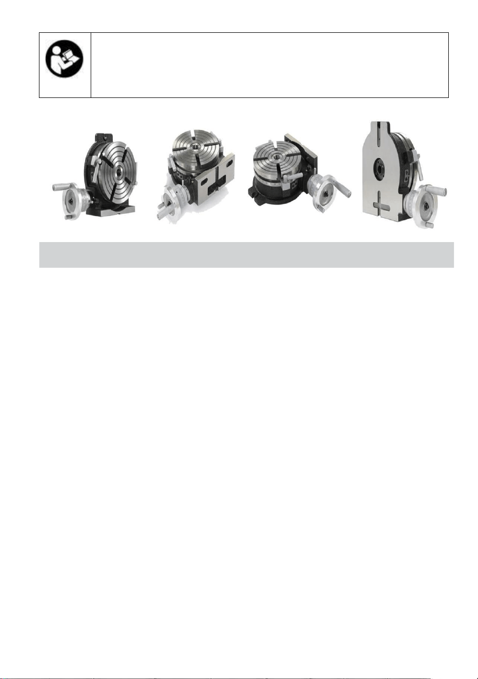
- 3 -
Waarschuwing-Om het risico op letsel te
verminderen, moet de gebruiker de instructies
lezen handmatig zorgvuldig .
PRECISION ROTARY TABLES
Er worden twee typen draaitafels samengevat hier collectief . De
mechanismen gewoon naar deze tafels worden op sommige pagina's
van hun beschrijving weergegeven .
HORIZONTAAL VERTICAAL _ PRECISIE ROTEREND
TAFEL
Dit roterend tafel is ontworpen om dit mogelijk te maken bewerking
activiteiten bij een hogere afmeting dan die van draaitafels van het
horizontale type . De basis kan zijn gebruikt in A verticale positie _ naar
inschakelen Het naar dragen uit het midden werk .
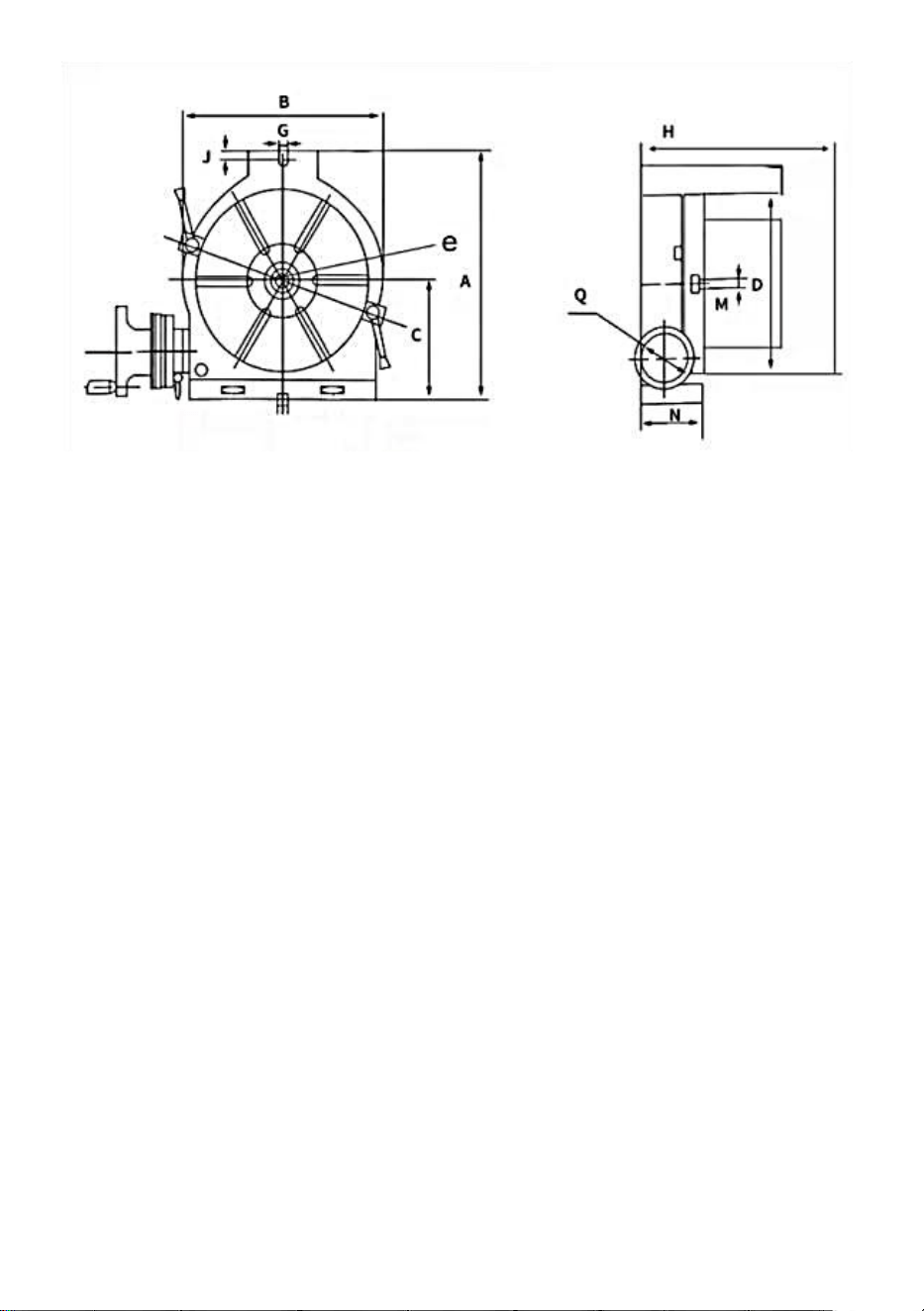
- 4 -
SPECIFICATIES : _
Eenheid:
mm/inch s

- 5 -
C
4.72”
120mm
3.35”
85mm
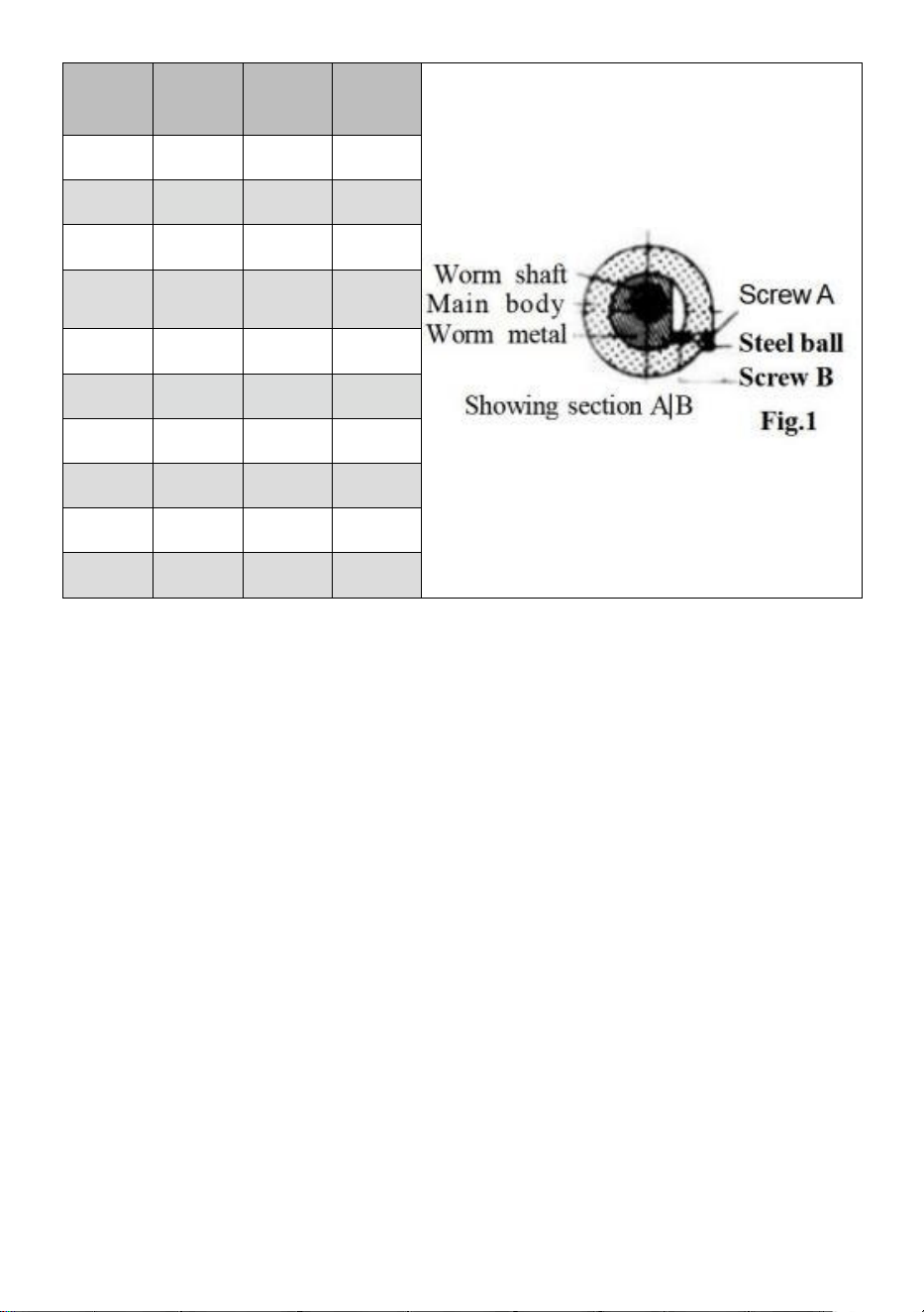
- 6 -
Model
_
HV - 3"
HV - 4"
HV - 5"
A
9 8
145
155
B
78
114
127
C
5 9
8 5.5
9 0
D
F7 6.2
_
F110
F1 27
_
E
1 2
1 2
1 2
G
H
8 3
8 5
8 5
J
1 5
M
MT2 _
MT2 _
N
71
68
68
1.Aanpassen Gaas van Worm Versnelling : Losmaken de metaal klem
hendel en draai _ de schakelaar metaal met de klok mee tot Het raakt de
stop . De worm uitrusting heeft nu geweest ontkoppeld . Draai Het tegen
de klok in tot Het raakt de stop, de worm En versnelling wiel zullen erbij
betrekken . Draai vast de metaal klem handvat na betrokkenheid . Een
extra aanpassing kan worden verkregen door te verwijderen de schroef
④ en stalen kogel en draai de binnenste schroef ⑥ tegen de klok in ,
zodat de worm nauwer in contact komt met het tandwiel wiel . Draaien
met de klok mee brengt de worm weg van het stuur. Na afstelling
invoegen de staal kogel en draai de schroef
④ vast
2.Axia l Aanpassing van Worm Schacht : Wanneer axiaal slap komt
voor versnelling aanpassing is gedragen uit door aanscherping de
binnenste wormasmoer nadat het handvat, de noniusring en het
schakelaarmetaal zijn verwijderd. Na aanpassing . vergrendel de moer op
de as door middelen van de set schroef . ( De ERT -6 heeft een
aanpassing noot , welke kan zijn gebruikt na verwijdering van het
handvat.)

- 7 -

- 8 -
Operatie _ Instructie En Functie van Elk Eenheid
1. De wormoverbrengingsverhouding is 1:90.
een draai van de hendel beweegt de tafel met 4 °
Micro - kraag is afgestudeerd in stappen van 1 min .
Nonius schaal maakt instellingen omlaag tot 10 seconden
mogelijk . (20 seconden ds voor ( HV 6)
2. Verdelen van 2 tot 100 kan snel en nauwkeurig worden
uitgevoerd door te bevestigen A Verdelen Mechanisme .
3. Midden werk kan Ook zijn gedragen uit door de basis in verticale
positie te gebruiken in combinatie met een losse kop. (Zie pagina 4.)
* Suggesties voor Volgorde
Wanneer bestellen onderdelen voor vervanging , aangeven Model Nee .
En Deel Nee .

- 9 -
OPTIONAL ACCESSORIES DIVIDING PLATES
RT met Verdelen _ Bord
SP ECIFICATIES VOOR VERDELEN PLATEN
Eenheid : mm / inch _
M
ODE
L
NEE
_
Grote afmetingen van DM
W acht
kg /
Ib
Van toepassing
tafel
Verdeelplaat e
stelschroef
_
Binnen
diameter
van
sector ben
Buitendi
ameter van
de veer
klem
Bosbreedte
_
in handvat
bord _
DP -
1
PCD.(32/ 1,26) F
2 1
0. 83
1 8
0. 71
9
0. 03
2 5
5. 51
MINI
(HV3H V4 / HV5
)
HV6
P7P9P10
_ _ _ _ _
DP -2
( 3 gaten)
PCD .
46/1,81
28. 7
1.12
44
1.73 _
1 0
0. 39
4
8. 82
HV8,10, 12, 14,16
P7P9P10
_ _ _ _ _
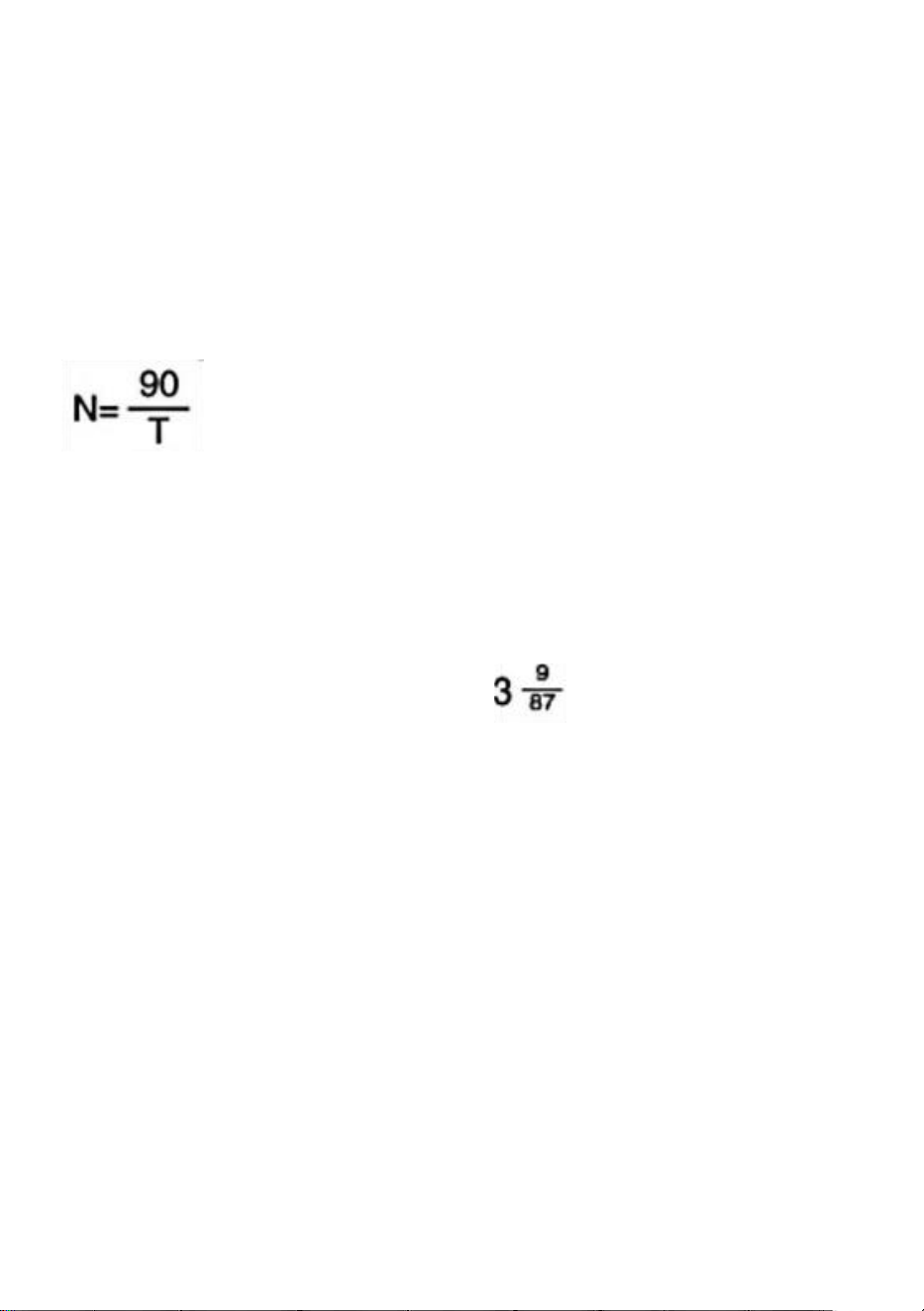
- 10 -
In geval van Een Optioneel DM Apparaat _ Bijgevoegd
Indexering van 2 tot 100 blikjes zijn gemaakt nauwkeurig en snel.
Vergelijking van Indexering _
Sinds de worm verhouding is 1:90, wanneer de handgreep 360°
kan draaien , wordt de tafel daarom zullen roteer een revolutie
van 1/90. De relaties tussen hendel revolutie ' N ' en individueel
nummer ' T ' tot zijn gevraagd Zijn getoond in de volgende
vergelijking:
Opmerkingen : De indextabel op pagina 6 is gemaakt op basis van deze
vergelijking.
( Voorbeeld )
In het geval waar de exploitant wil naar inhoudsopgave de positie
verdeeld in 29 gelijk onderdelen . Tips op operatie Als voor 29 personen
cijfers , de nummer
van kruk hendel omwentelingen ( N ) is als getoond in de tafel
op Bladzijde
6, dus Dat de hendel moet driemaal plus een volledige 360°-omwenteling
worden gedraaid een interval van negen gaten ( in dit tijd , het betekent
gatintervallen en niet gatnummers ). Na instelling dit punt als A begin punt ,
draai de hendel een volledige omwenteling van 360° drie keer plus een
interval van negen gaten ( in dit tijd , betekent het gat intervallen niet gat
nummers ). Nadat u dit punt als startpunt hebt ingesteld , draait u de
handgreep driemaal een volledige omwenteling van 360° plus een interval
van negen gaten . Wanneer de procedure is op zijn beurt maar liefst 29
keer herhaald, de indexering van verdelen in 29 gelijke delen wordt aldus
bereikt.

- 11 -

- 12 -
Activiteiten _ van Zwengel Hendel En Sector
In geval dat van de Voorbeeld ' Divisie in 29 Gelijk Onderdelen '
voornoemd , it is Het is logisch dat de indexeringsoperatie doorgaat met
de intervallen van negen gaten na het instellen de inhoudsopgave plaat
( B plaat ) aan welke A rij van 87 gaten voorzien . Maar bij deze
methode moet de operator de intervallen van negen gaten één tellen
door een . Hij moet inefficiënt aanvoelen. Vanuit dit oogpunt is het
noodzakelijk om een apparaat genaamd 'sector' te gebruiken om id te
vermijden zo een lastig procedures . De volgende wil beschrijven
sommige noodzakelijke procedures voor de werking van de sector.

- 13 -
A . Losmaken de kruk hendel slot moer ,
pas deze aan lengte Dus als naar oorzaak
de inhoudsopgave pin naar erin vallen de
trein van 87 gaten , en vastdraaien Het .
B . Losmaken de stelschroeven _ _ van de
sector . twee openen armen in
overeenstemming met de interval van negen
gaten ( totaal cijfers van gaten is tien ) , en
vastdraaien met stelschroeven .
C . Eerst brengen _ de links arm van de
sector dichtbij de inhoudsopgave speldjes _
_ links kant .
D . Draai vervolgens _ de kruk hendel met
de klok mee toepassen Het naar de rechts
arm van de sector Dus dat de
inhoudsopgave pin zullen val in de gat
gelegen Op deze rechts armen _ _ links
kant oppervlak .
e . Draaien de sector met de klok mee dit
tijd en zet de rechts kant oppervlak van de
links arm naar de links kant van de
inhoudsopgave speld . In dit tijd , de relaties
tussen de inhoudsopgave pin En de sector
_ links arm in hun posities Zijn hetzelfde als
in Par . C ).
De inhoudsopgave bord gat Dat
daadwerkelijk herbergt de inhoudsopgave
pin is gelegen bij de punt waar Het gaat
over tien gaten naar de rechts weg van de
gat als in par . c ) c . F . Herhalen de
dezelfde procedures als nodig .
Krukgreep _
Inhoudsopgave pen
Afb 5
Afb 6
Afb . 7
Afb 8
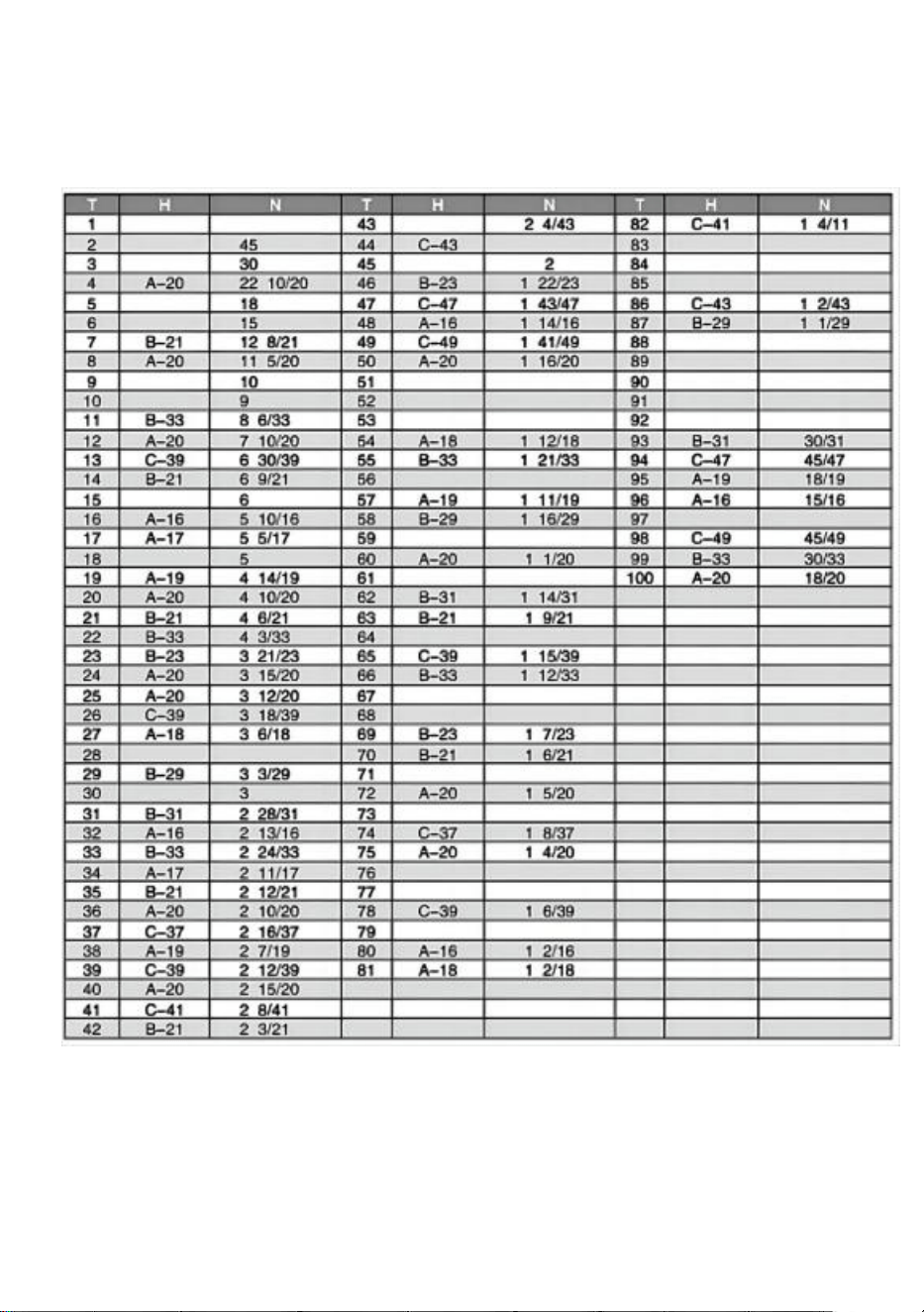
- 14 -
Inhoudsopgave Tabel ( voor worm verhouding 1: 90) DP-1 Voor
HV6/MINI(HV3/HV4/HV5)

- 15 -
DP -2 Voor HV 8, HV 10, HV 12, HV 14, HV 1 6
Beschrijving van in de inhoudsopgave tafel.
Deze tafel is de een wezen berekend voor de inhoudsopgave bord
met gat getoonde nummers onderstaand .
Beschrijving _ van codes gebruikt in de inhoudsopgave tafel
T: Gewenst individueel nummer r

VADER
- 16 -
N: Aantal f revoluties van de inhoudsopgave bord
: Keuze _
A : Gebruik makend van A bord
B : Gebruik makend van B bord
Nummer van gaten
DP - 1
Een bord
15 , 16,17, 18,19,20
B Bord
21,23,2 7,29,31,33
CP laat
DP - 2
37,39,41,4 3,47,49
Een bord
26,28,
30,32,34,37,38,39,41,43,44,46,47,49,51,53,57,59
B Bord
61,63,6 7,69,71,73,77,79,81,83,87,89,91,93,97,99

- 17 -
ONDERDELEN LIJST
Model HV-4-KP
1. Voornaamst lichaam * 1
2. Hendel * 2
3. Chuck moersleutel * 1
4. Achteruit _ kaken * 1 set (3 stuks )
5. M10 _ * 40 T - bout * 2
6. M10 noot * 2
7. Instructies * 1
Model HV-4-4
1. Voornaamst lichaam * 1
2. Hendel * 2
3. M6 * 55 bout * 2
4. M6 noot _ * 2
5. φ 6 vlak pakking * 2
6. Positionering _ blok * 2
7. Drukken bord _ * 2
8 . Kussen blok * 2
9. Instructies * 1
10 . A partitie bord * 1
11 . B partitie bord * 1
12 . C partitie bord * 1
13 . Rocker hendel * 1
14 . M 8 * 70 hex stopcontact hendel schroef * 1
15 . Divisie bord positionering regelaar * 1
16 . Begrenzing blok * 1
17 . Borgring * 1
18 . M5 * 10 Philips schroef * 3

- 18 -
Model HV-4-4R
1. Voornaamst lichaam * 1
2. Hendel * 2
3. M6 * 55 bout * 2
4. M6 noot _ * 2
5. φ 6 vlak pakking * 2
6. Positionering _ blok * 2
7. Drukken bord _ * 2
8 . Kussen blok * 2
9. Instructies * 1
Model HV-6-4B
1 . A partitie bord * 1
2. B partitie bord * 1
3 . C partitie bord * 1
4 . Rocker hendel * 1
5. M 8 * 70 hex stopcontact hendel schroef * 1
6. Divisie bord positionering regelaar * 1
7. Begrenzing blok * 1
8 . Borgring * 1
9. M5 * 10 Philips schroef * 3
10. M5 _ * 10 hex stopcontact schroef * 4
11. Positionering _ blok * 4
12. M 12 * 40 T - bout * 2
13 . Noot * 2
14. Intern zeshoekig moersleutel * 1
1 5. Instructies * 1

- 19 -
Model HV-6-4
1. Voornaamst lichaam * 1
2. Rocker hendel * 1
3. M 8 * 7 0 hex stopcontact hendel schroef * 1
4 . M5 * 10 hex stopcontact schroef * 4
5. Positionering blok * 4
6. M12 * 40 T-bout * 2,
7. Noot * 2
8 . Instructies * 1
Model HV-8-4
1. Voornaamst lichaam * 1
2 . Hendel * 2
3. Noot * 2
4. M10 _ * 80 zeshoekig hendel bout * 1
5. Positionering blok * 4
6. M5 _ * 8 zeshoekig stopcontact bout * 4
7. M 14 * 60 T-bout * 2
8. Intern zeshoekig moersleutel * 1
9. Instructies * 1
Model HV-8-3
1. Voornaamst lichaam * 1
2. Hendel * 2
3. M 1 0 * 80 hex stopcontact hendel schroef * 1
4. Positionering _ blok * 4
5. M5 * 8 h exagonaal stopcontact bout * 4
6. M 14 * 60 T - bout * 2
7. Intern zeshoekig moersleutel * 1
8. Noot * 2
9. Instructies * 1

- 20 -
Adres: Baoshanqu Shuangchenglu 803long 11hao 1602A-1609shi
Shanghai
Geïmporteerd naar AUS: SIHAO PTY LTD . 1 ROKEVA
STREETEASTWOOD NSW 2122 Australië
Geïmporteerd naar de VS: Sanven Technology Ltd. Suite 250 . 9166
Anaheim Place, Rancho Cucamonga, CA 91730
REP
EC
SHUNSHUN GmbH
Römeräcker 9 Z2021, 76351 Linkenheim-
Hochstetten, Germany
REP
UK
Pooledas Group Ltd
Unit 5 Albert Edward House, The
Pavilions Preston, United Kingdom
Gemaakt in China


Teknisk support och e-garanticertifikat
www.vevor.com/support
R OTARY TABELL
MODELL : HV-4-KP, HV-4-4, HV-4-4R,
HV-6-4, HV-6-4B, HV-8-4 , HV-8-3
We continue to be committed to provide you tools with competitive price.
"Save Half", "Half Price" or any other similar expressions used by us only represents an
estimate of savings you might benefit from buying certain tools with us compared to the
major top brands and does not necessarily mean to cover all categories of tools offered by
us. You are kindly reminded to verify carefully when you are placing an order with us if you
are actually saving half in comparison with the top major brands.

- 1 -
ROTARY TABLE
MODELL : HV-4-KP, HV-4-4, HV-4-4R, HV-6-4, HV-6-4B, HV-8-4 HV-8-3
BEHÖVER HJÄLP ? KONTAKT USA !
Ha produkt frågor ? Behöver teknisk Stöd ? Snälla du känna fri
kontakta oss :
Teknisk Stöd och E - Garanti Certifikat www
. vevor . se / support
Detta är de original instruktioner, läs alla manualer noggrant innan du
använder den. VEVOR reserverar sig för en tydlig tolkning av vår
användare manual . De utseende av de produkten ska vara föremål för
produkten du mottagen. Förlåt oss att vi inte kommer att informera dig
igen om det finns är några teknologi eller programvara uppdateringar på
vår produkt .
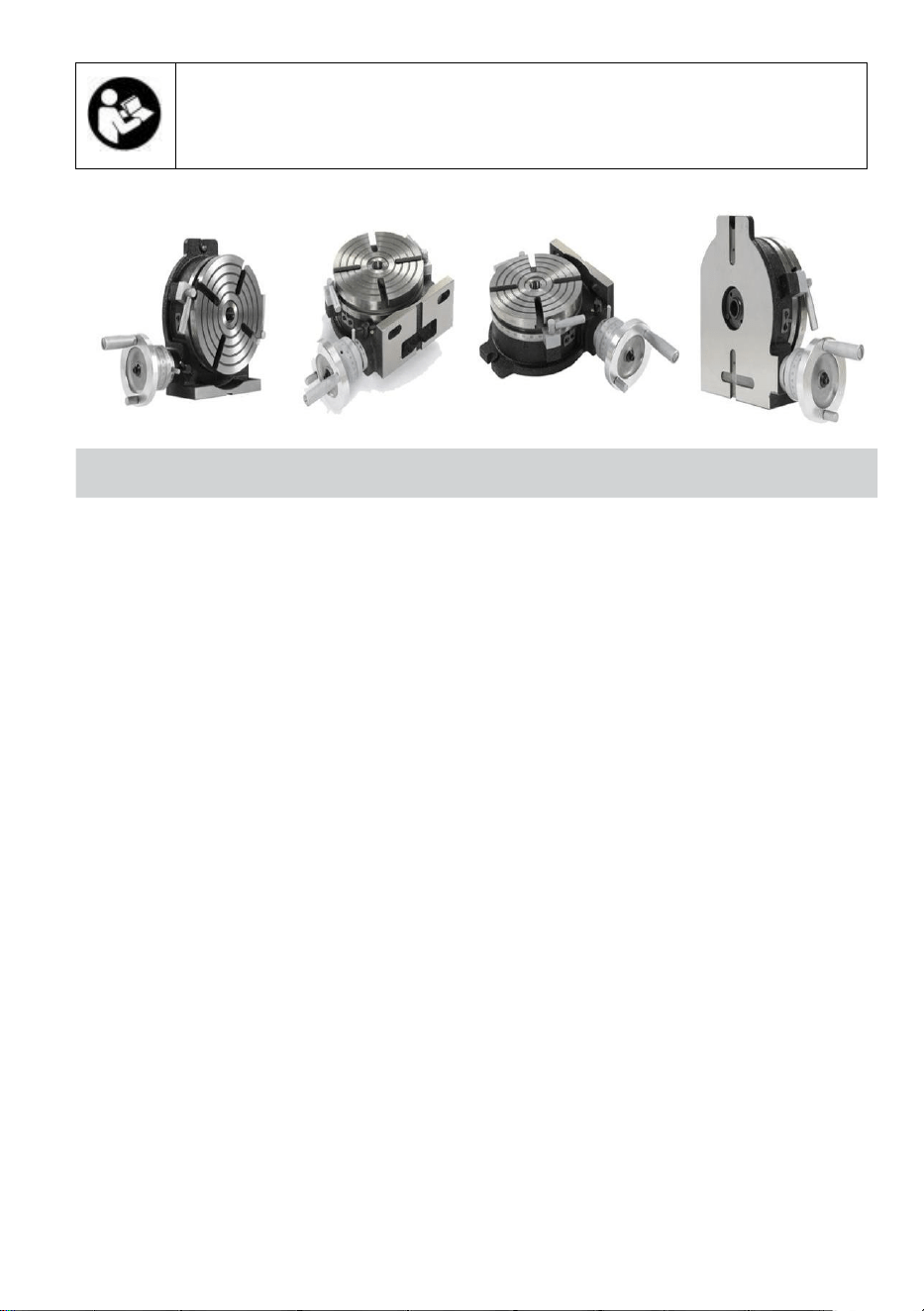
- 2 -
- För att minska risken för skador måste
användaren läsa instruktionerna manuell försiktigt .
PRECISION ROTARY TABLES
Två typer av roterande bord är sammanfattade här kollektivt .
Mekanismerna allmänning till dessa tabeller visas på vissa sidor i
deras beskrivning .
HORISONTALT / VERTIKAL PRECISION ROTERANDE
TABELL
Detta roterande tabell är designad för att tillåta det bearbetning
operationer på en högre dimension än den för horisontella typ roterande
bord s . Basen kan _ vara Begagnade i a vertikal position _ till Gör det
möjligt Det till bära ut i mitten arbeta .

- 3 -
SPE CIFIKATIONER :
Enhet: mm/tum
s

- 4 -
C
4.72”
120mm
3.35”
85mm

- 5 -
Modell
_
HV - 3"
HV - 4"
HV - 5"
A
9 8
145
155
B
78
114
127
C
5 9
8 5,5
9 0
D
F 7 6,2
F110
F 1 27
E
1 2
1 2
1 2
G
H
8 3
8 5
8 5
J
1 5
M
MT 2
MT 2
N
71
68
68
1. Justering Maska av Mask Kugghjul : Lossa de metall klämma
hantera och vänd _ de växla metall medurs fram tills Det berör de propp .
De mask redskap har nu varit urkopplad . Sväng Det moturs fram tills Det
berör proppen , w ormen och redskap hjul kommer förlova sig . Spänna
de metall klämhandtag efter engagemang . En ytterligare justering kan
erhållas genom att ta bort de skruv
④
och stålkula och vrid den inre
skruven ⑥ moturs , så att masken kommer i närmare ingrepp med
kugghjulet hjul . Vändning medurs ger de mask bort från hjulet. Efter
justering Föra in de stål kula och dra åt skruven
④
2.Axia l Justering av Mask Skaft : När axial slak inträffar växeljustering
är bärs ut förbi åtstramning den inre muttern på snäckaxeln efter att
handtaget, nockringen och brytarmetallen har tagits bort. Efter justering .
lås muttern på axeln förbi betyder av de uppsättning skruv . ( Den ERT -6
har en justering mutter , som burk vara används efter att handtaget tagits
bort.)

- 6 -
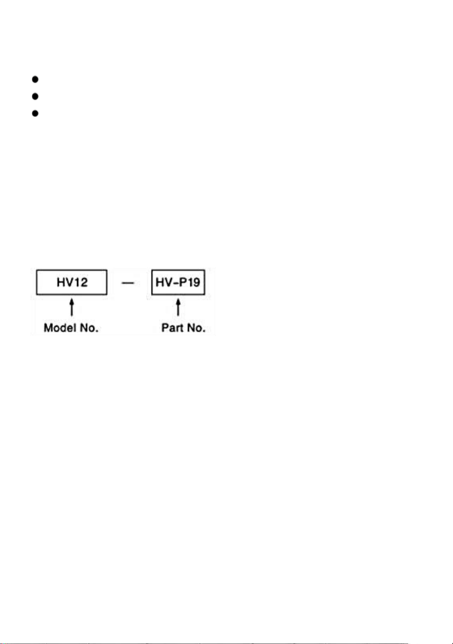
- 7 -
Drift _ Instruktion och Fungera av Varje Enhet
1. Den snäckväxel är 1:90.
ett tum av de hantera rör sig de tabell med 4 °
Micro - krage är tog examen i steg på 1 min .
Nonieskala skala gör inställningar ner till 10 sekunder
möjligt . (20 sekunders ds för ( HV 6)
2. Dela av 2 till 100 kan utföras snabbt och exakt genom att fästa
a Dela Mekanism .
3. Center arbete burk också vara bärs ut genom att använda basen i
vertikalt läge i kombination med en ändstock.(Se sidan 4.)
* Förslag för Beställa
När beställning delar för byte , ange Modell Nej . och Del Nej .

- 8 -
OPTIONAL ACCESSORIES DIVIDING PLATES
RT med Dela ing Tallrik
SP ECIFIKATIONER FÖR DELANDE PLATTOR
Enhet : mm / tum _
MODEL
L _
NEJ
_
Större dimension jon av DM
W åtta
kg /
Ib
Tillämplig tabell
Delningsplatta e
ställskruv _
Inre
diameter av
sektor am
Fjädern
s
ytterdiamet
er klämma
Grove med
dth
i
handtaget
p sent
DP -
1
PCD.(32/1,26) F
2 1
0. 83
1 8
0. 71
9
0. 03
2 5
5. 51
MINI
(HV3H V 4/ HV
5)
HV6
P 7 P 9 P
10
DP -2
( 3 hål)
PCD .
46/1,81
28. 7
1.12
44
1,73 _
1 0
0, 39
4
8. 82
HV8,10, 12, 14,16
P 7 P 9 P
10
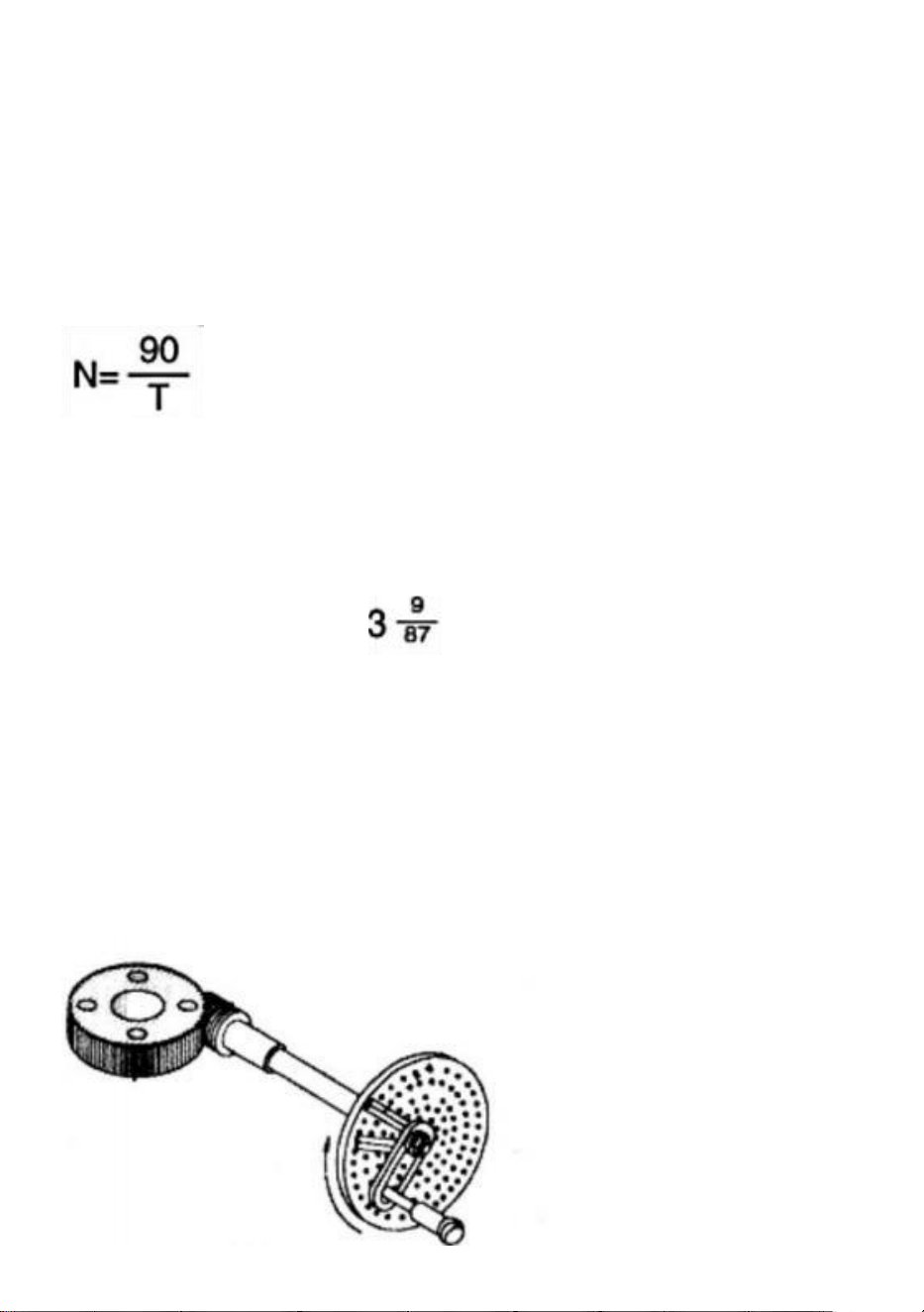
- 9 -
I fall av En Frivillig DM Enhet _ Bifogad
Indexering på 2 till 100 burkar vara gjord exakt och snabbt.
Ekvation av Index ing
Eftersom de mask förhållande är 1:90, när handtaget är gjort att
rotera ett varv 360 ° , tabell därför kommer rotera en 1/90 varv.
Relationerna mellan hantera varv ' N ' och individuellt nummer ' T
' till vara eftersträvas är visad i följande ekvation:
Anmärkningar : The indextabellen på sidan 6 är gjord på basis av denna
ekvation.
( Exempel )
I fall där de operatör vill ha till index de placera dividerat till 29 lika delar .
Tips på drift Som för 29 personer siffror , den siffra
av vev hantera varv ( N ) är som visad i de tabell på Sida
6, alltså den där de hantera ska roteras ett helt varv 360° plus tre gånger
en intervall av nio hål ( in detta tid , det betyder hålintervall inte hålnummer)
. Efter miljö detta punkt som a Start peka , vrid handtaget ett helt varv
360° tre gånger plus en intervall av nio hål ( in detta tid betyder det hål
intervaller inte hål tal ). Efter att ha ställt in denna punkt som startpunkt ,
rotera handtaget ett helt 360° varv tre gånger plus ett intervall på nio hål .
När de procedur är upprepas i tur och ordning så många som 29 gånger,
indexeringen av delning till 29 lika delar uppnås således.

- 10 -
Operationer _ av Vev Hantera och Sektor
Om _ av de Exempel ' Division till 29 lika Delar ' ovannämnda , det är
naturligt att indexeringsoperationen fortsätter med de intervaller av nio
hål efter inställning de index tallrik ( B plåt ) på som a rad med 87 hål är
försedda . Men i denna metod måste operatören räkna nio håls intervall
ett förbi ett . han måste kännas ineffektivt. I denna synvinkel är det
nödvändigt att använda en enhet som kallas "sektor" för att undvika id
sådan besvärlig förfaranden . De följande testamente beskriva några
nödvändiga förfaranden för driften av sektorn.
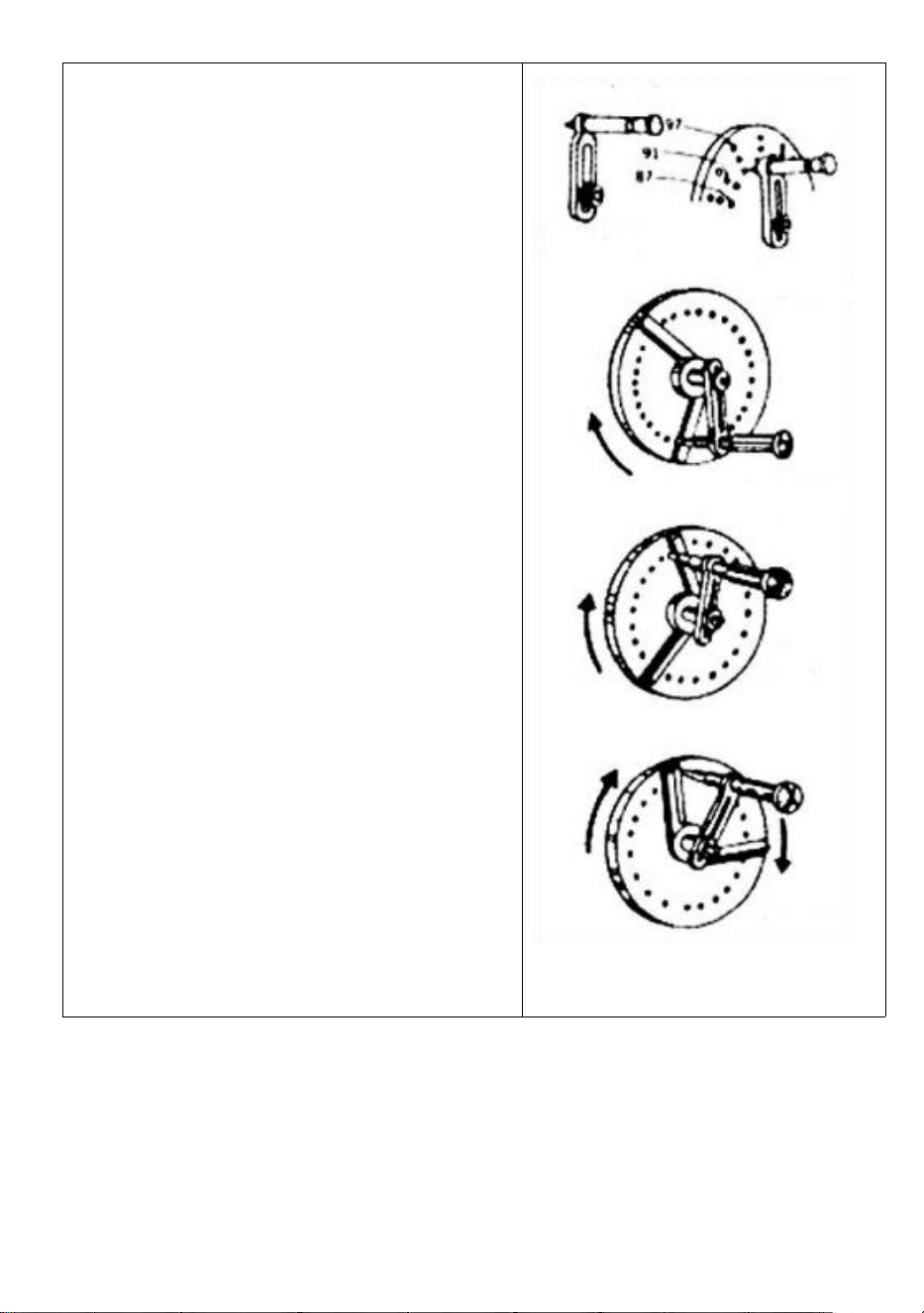
- 11 -
a . Lossa de vev hantera låsa mutter ,
justera dess längd så som till orsak de index
stift till falla in de tåg av 87 hål , och spänna
Det .
b . Lossa de set - skruvar av de sektor .
öppna två vapen i överensstämmelse med
de intervall av nio hål ( totalt tal av hål är tio
) , och spänna med ställskruvar .
c . Först , ta med de vänster ärm av de
sektor nära de index stift _ _ vänster sida .
d . Nästa , rotera de vev hantera medurs
att ansöka Det till de höger ärm av de sektor
så Att den index stift kommer falla i de hål
belägen vid denna höger armar _ _ vänster
sida yta .
e . Rotera de sektor medurs detta tid och
lägg de höger sida yta av de vänster ärm till
vänster sida av de index stift . I detta tid ,
relationerna mellan de index stift och
sektorns _ _ vänster ärm i deras positioner
är det samma som i Par . c ).
De index tallrik hål den där faktiskt rymmer
de index stift är belägen vid punkt var Det
går tvärs över tio hål till höger bort från de
hål som i par . c ) c . f . Upprepa de
samma förfaranden som nödvändigt .
Vevhandtag e
Index penna
Fikon
5
Fikon
6
F ig 7
Fikon
8

- 12 -
Index Tabell ( För mask förhållande 1:90 ) DP-1 För
HV6/MINI(HV3/HV4/HV5)

- 13 -
DP -2 För HV 8, HV 10, HV 12, HV 14, HV 1 6
Beskrivning av i de index tabell.
Det här bordet är inte han ett varelse beräknad för de index tallrik
med hål siffror visas Nedan .
Beskrivning på av koder Begagnade i de index tabell
T: Önskat individuellt nummer r

PA
- 14 -
N: Antal f revolutioner av de index tallrik
:O p tion
A : Använder sig av A tallrik
B : Använder sig av B tallrik
siffra av hål
DP - 1
En tallrik
15 , 16,17, 18,19,20
B Tallrik
21,23,2 7,29,31,33
CP sent
DP - 2
37,39,41,4 3,47,49
En tallrik
26,28,
30,32,34,37,38,39,41,43,44,46,47,49,51,53,57,59
B Tallrik
61,63,6 7,69,71,73,77,79,81,83,87,89,91,93,97,99

- 15 -
DELLISTA
Modell HV-4-KP
1. Main kropp * 1
2. Hantera * 2
3. kasta rycka * 1
4. Omvänd _ käftar * 1 uppsättning (3 st )
5. M 10 * 40 T - bult * 2
6. M10 nöt * 2
7. Instruktioner * 1
Modell HV-4-4
1. Main kropp * 1
2. Hantera * 2
3. M6 * 55 bult * 2
4. M6 nöt _ * 2
5. φ 6 platt packning * 2
6. Positionering _ blockera * 2
7. Brådskande p sent * 2
8 . Prydnadskudde blockera * 2
9. Instruktioner * 1
10 . A dela styrelse * 1
11 . B dela styrelse * 1
12 . C dela styrelse * 1
13 . Rocker hantera * 1
14 . M 8 * 70 hex uttag hantera skruva * 1
15 . Division tallrik positionering regulator * 1
16 . Begränsa blockera * 1
17 . Låsring * 1
18 . M5 * 10 Phillips skruva * 3

- 16 -
Modell HV-4-4R
1. Main kropp * 1
2. Hantera * 2
3. M6 * 55 bult * 2
4. M6 nöt _ * 2
5. φ 6 platt packning * 2
6. Positionering _ blockera * 2
7. Brådskande p sent * 2
8 . Prydnadskudde blockera * 2
9. Instruktioner * 1
Modell HV-6-4B
1 . A dela styrelse * 1
2. B dela styrelse * 1
3 . C dela styrelse * 1
4 . Rocker hantera * 1
5. M 8 * 70 hex uttag hantera skruva * 1
6. Division tallrik positionering regulator * 1
7. Begränsa blockera * 1
8 . Låsring * 1
9. M5 * 10 Phillips skruva * 3
10. M 5 * 10 hex uttag skruva * 4
11. Positionering _ blockera * 4
12. M 12 * 40 T - bult * 2
13 . Nöt * 2
14. Inre hexagonal rycka * 1
1 5. Instruktioner * 1

- 17 -
Modell HV-6-4
1. Main kropp * 1
2. Rocker hantera * 1
3. M 8 * 7 0 hex uttag hantera skruva * 1
4 . M5 * 10 hex uttag skruva * 4
5. Positionering blockera * 4
6. M12 * 40 T-bult * 2,
7. Nöt * 2
8 . Instruktioner * 1
Modell HV-8-4
1. Main kropp * 1
2 . Hantera * 2
3. Nöt * 2
4. M 10 * 80 hexagonal hantera bult * 1
5. Positionering blockera * 4
6. M 5 * 8 hexagonal uttag bult * 4
7. M 14 * 60 T-bult * 2
8. Inre hexagonal rycka * 1
9. Instruktioner * 1
Modell HV-8-3
1. Main kropp * 1
2. Hantera * 2
3. M 1 0 * 80 hex uttag hantera skruva * 1
4. Positionering _ blockera * 4
5. M5 * 8 h exagonal uttag bult * 4
6. M 14 * 60 T - bult * 2
7. Inre hexagonal rycka * 1
8. Nöt * 2
9. Instruktioner * 1

- 18 -
Adress: Baoshanqu Shuangchenglu 803long 11hao 1602A-1609shi
Shanghai
Importerad till AUS: SIHAO PTY LTD . 1 ROKEVA
STREETEASTWOOD NSW 2122 Australien
Importerad till USA: Sanven Technology Ltd. Svit 250 . 9166 Anaheim
Place, Rancho Cucamonga, CA 91730
REP
EC
SHUNSHUN GmbH
Römeräcker 9 Z2021, 76351 Linkenheim-
Hochstetten, Germany
REP
UK
Pooledas Group Ltd
Unit 5 Albert Edward House, The
Pavilions Preston, United Kingdom
Tillverkad i Kina