
Technical Support and E-Warranty Certificate
www.vevor.com/support
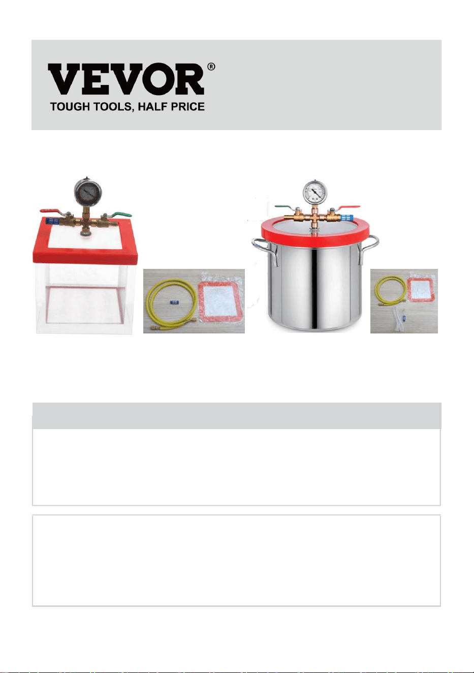
VACUUM CHAMBER
INSTRUCTIONS
MODEL:Y2/T3/T5/T1.5
We continue to be committed to provide you tools with competitive price.
"Save Half", "Half Price" or any other similar expressions used by us only represents an
estimate of savings you might benefit from buying certain tools with us compared to the major
top brands and does not necessarily mean to cover all categories of tools offered by us. You
are kindly reminded to verify carefully when you are placing an order with us if you are
actually saving half in comparison with the top major brands.

- 1 -
MODEL:Y2/T3/T5/T1.5
Have product questions? Need technical support? Please feel free to
contact us:
Technical Support and E-Warranty Certificate
www.vevor.com/support
NEED HELP? CONTACT US!
This is the original instruction, please read all manual instructions
carefully before operating. VEVOR reserves a clear interpretation of our
user manual. The appearance of the product shall be subject to the
product you received. Please forgive us that we won't inform you again if
there are any technology or software updates on our product.
VACUUM CHAMBER

- 2 -
IMPORTANT SAFEGUARDS
WARNING: Read this material before using this product.
Failure to do so can result in serious injury.
Assembly precautions
1. Assemble only according to these instructions. Improper assembly can
create hazards.
2. Keep the assembly area clean and well-lit.
3. Keep bystanders out of the area during assembly.
4. Do not assemble when tired or when under the influence of alcohol,
drugs or medication.
5. The product capabilities apply to properly and completely assembled
products only.
CAUTION :
1) When the vacuum gauge of the vacuum barrel is connected with the
acrylic plate, rubber rings must be installed on the upper and lower sides,
otherwise ,there will be air leakage.
2) In some cases, the red rubber ring on the outer edge of the chamber
cover may be uneven, causing poor sealing when directly placed on the
chamber. This can result in the vacuum gauge showing no pressure
response. To resolve this issue, follow these steps:
a. Start the vacuum pump.
b. Using both hands, firmly press down on the chamber cover for
approximately 5 seconds.
c. Release the pressure on the chamber cover after observing the
rotation of the pointer on the vacuum gauge.
d. The rotation of the vacuum gauge pointer indicates that the
vacuum chamber and vacuum pump are operating normally.
e. By applying this treatment, you can ensure proper sealing and
establish the normal operation of the vacuum chamber and
vacuum pump.
Use precautions
- 3 -
WARNING: TO PREVENT SERIOUS INJURY FROM TIPPING:
1. This product is not a toy. Do not allow children to play with this item.
2. Use as intended only. Do not stand or sit on the product.
3. Make sure the red rubber ring is not loose before each use.
SAVE THESE INSTRUCTIONS
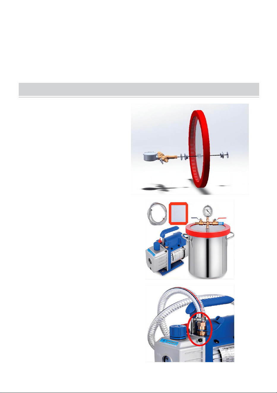
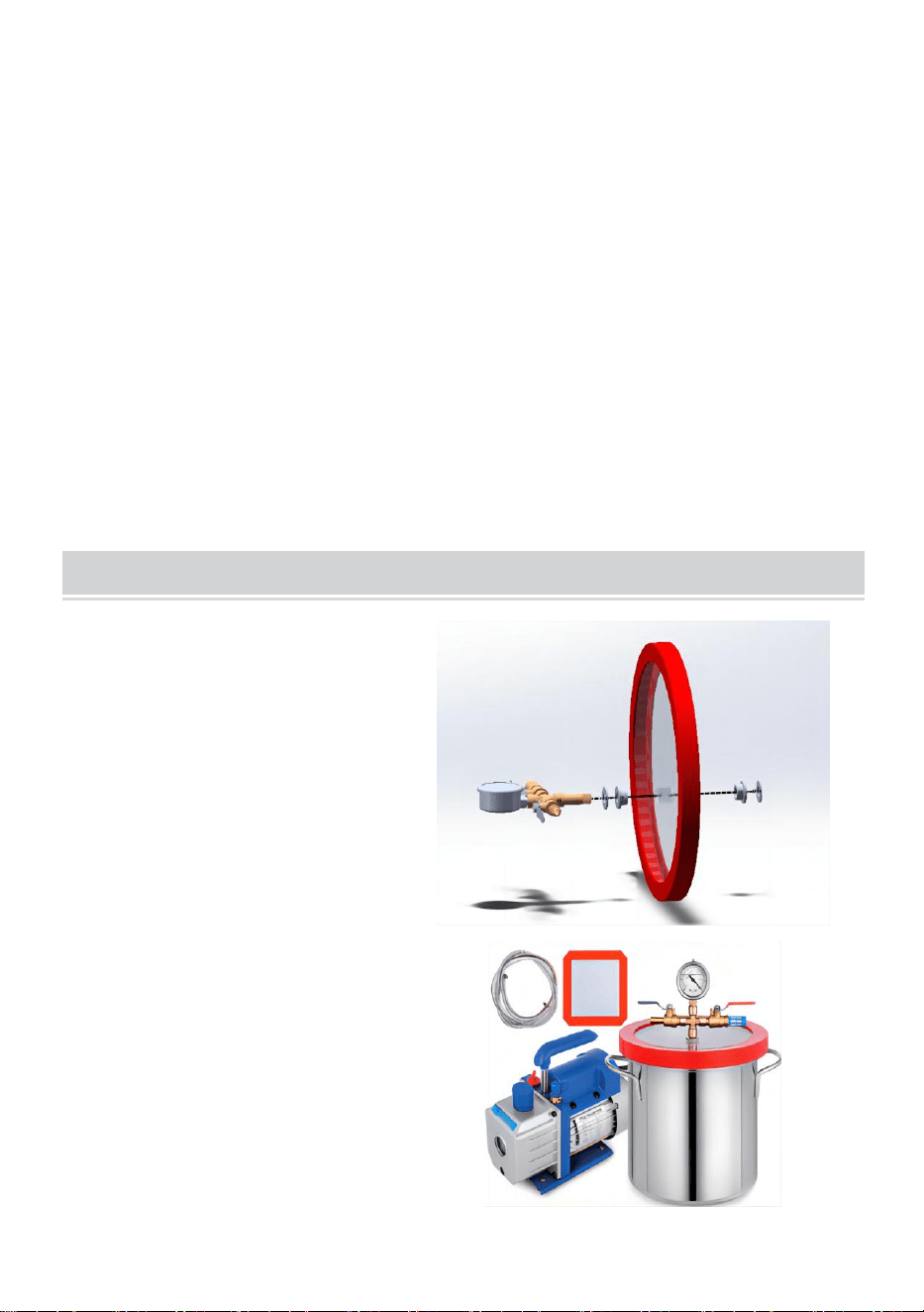
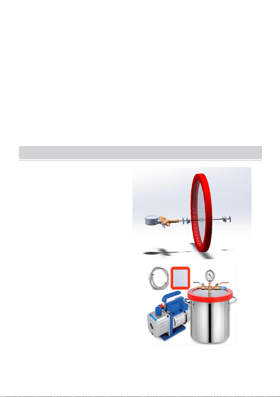
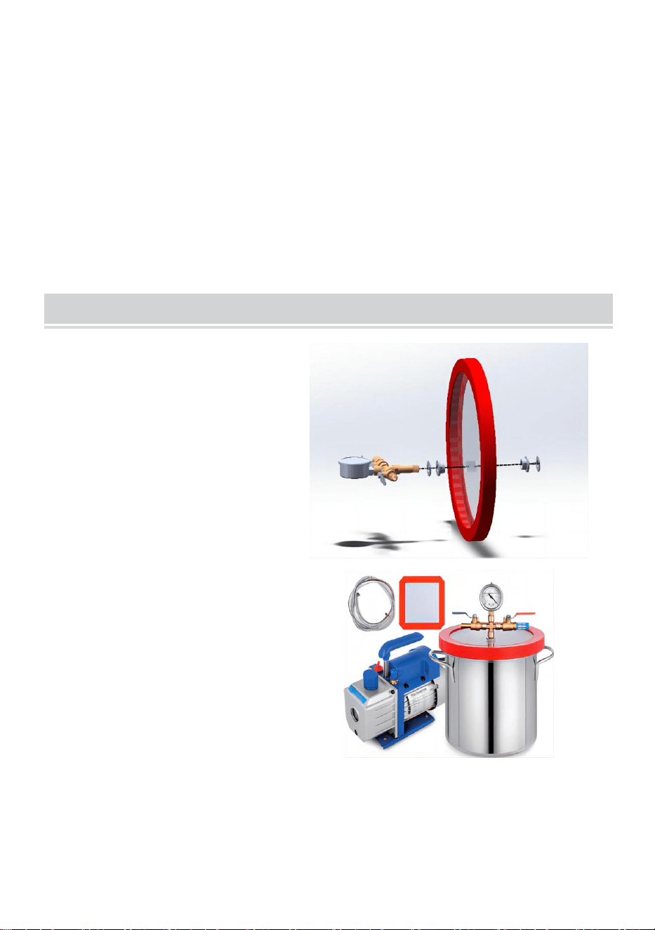
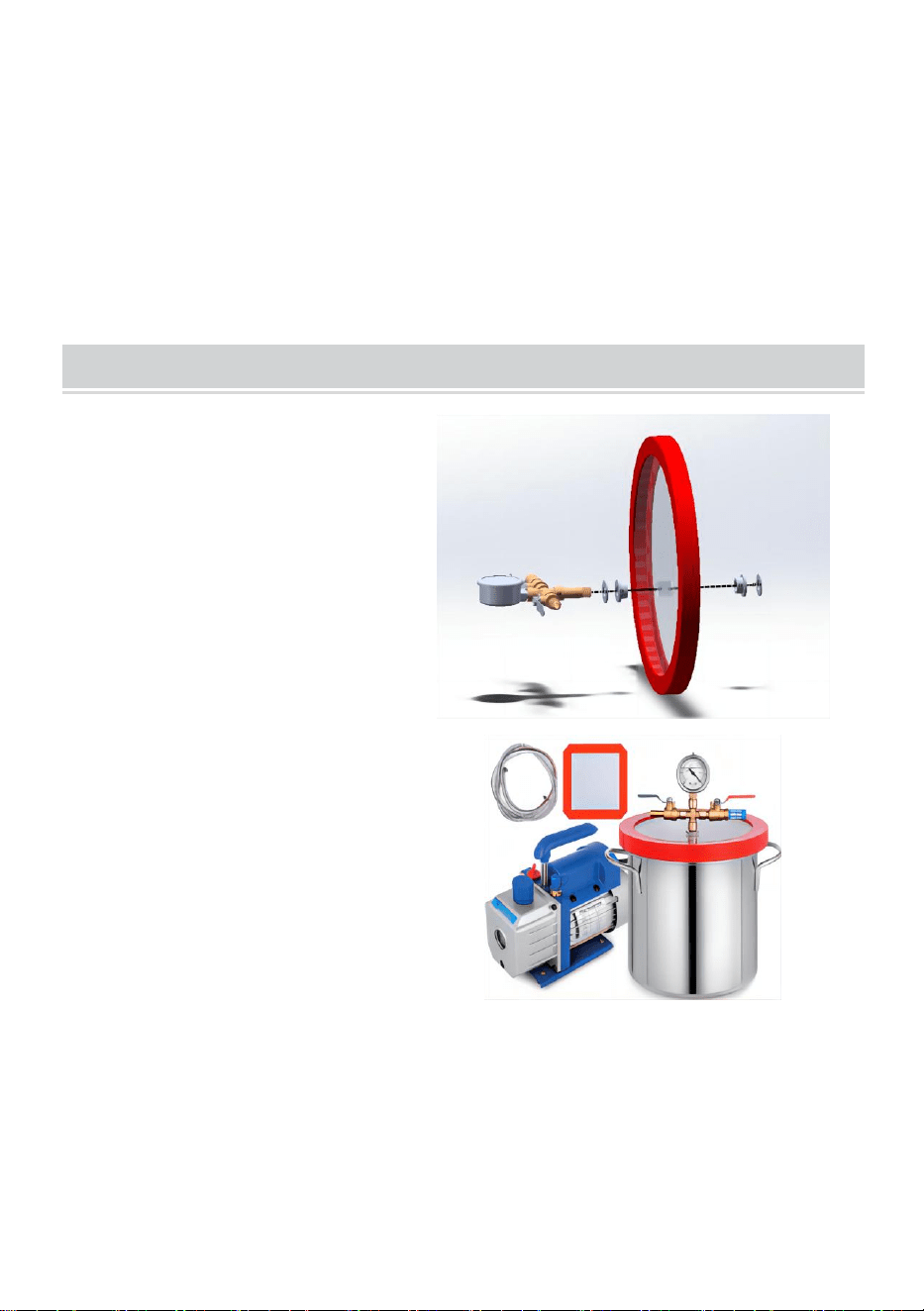
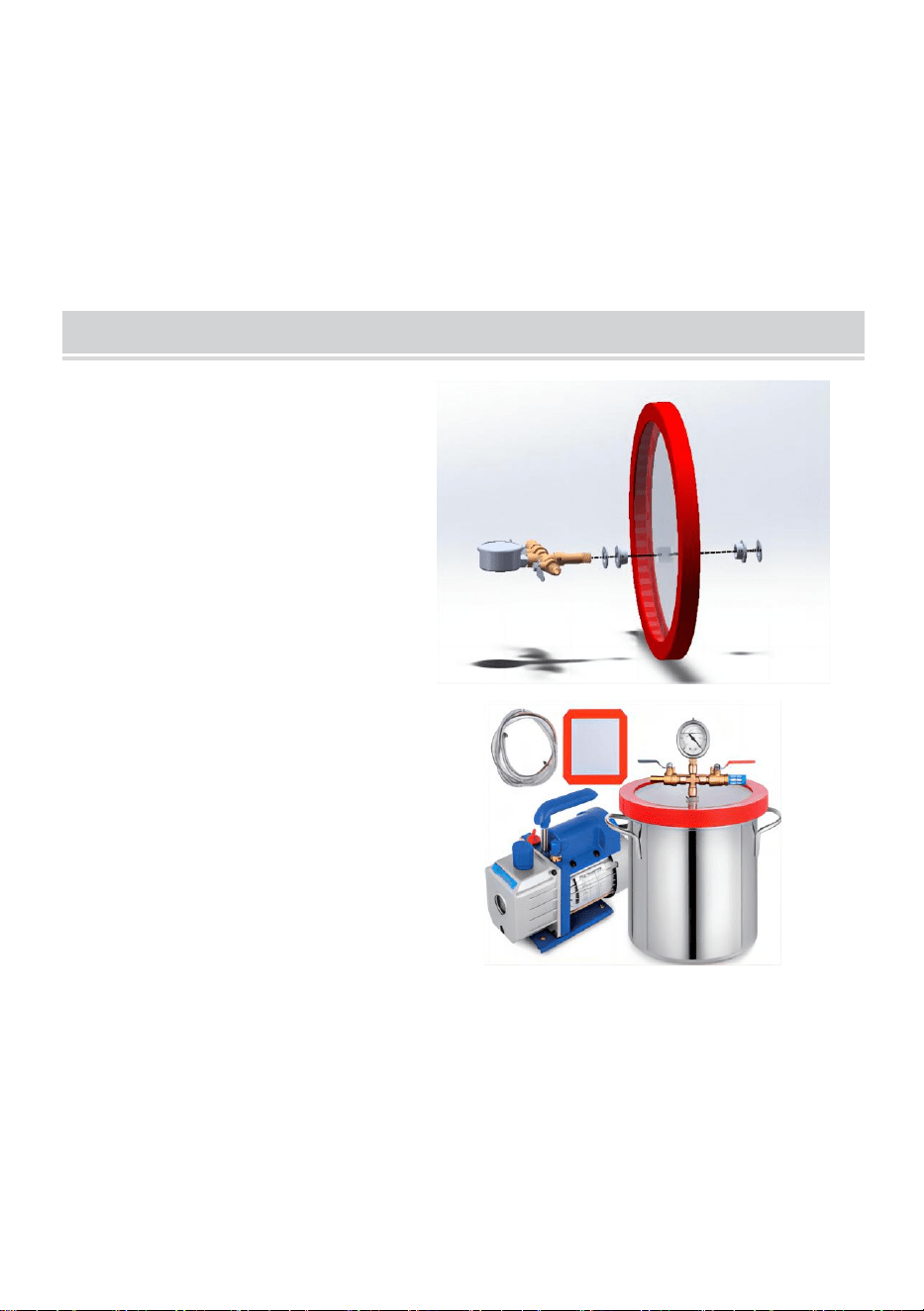
INSTRUCTIONS FOR VACUUM PUMP AND VACUUM CHAMBER
1.After removing the vacuum
gauge assembly, install the
vacuum gauge assembly in
the order shown in the
diagram, and then tighten the
nut with appropriate force.
2. Prepare 1vacuum pump, 1
vacuum chamber, and vacuum
pump oil.
3. After filling the vacuum
pump, connect the hose to
the air inlet nozzle of the
vacuum pump.
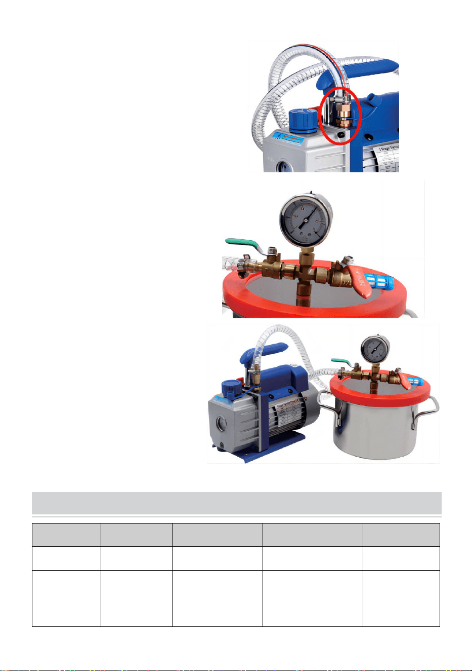
- 4 -
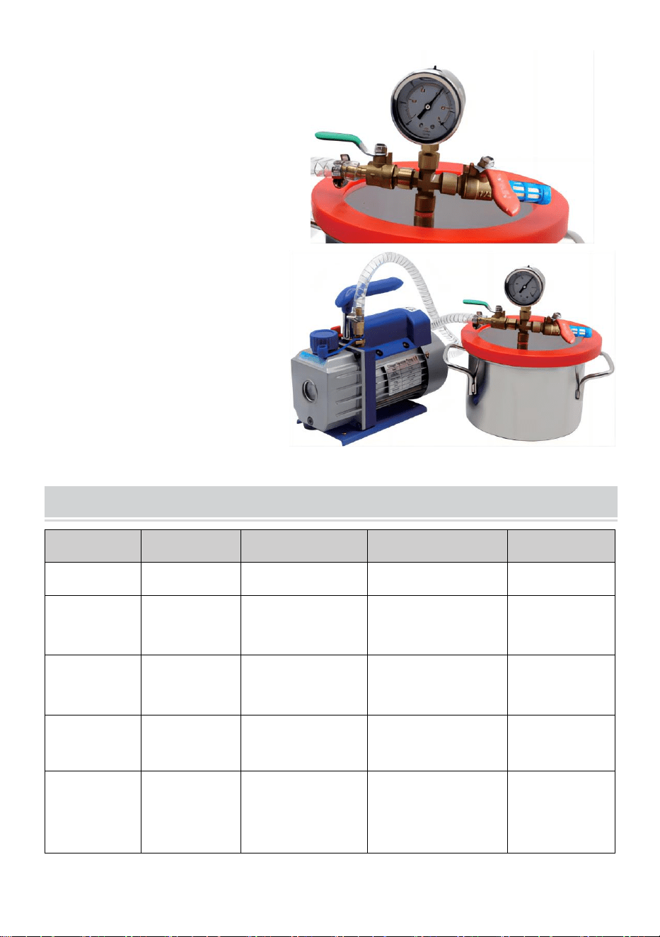
4. The interface at the other end
of the hose is connected with the
vacuum gauge, and the valve
switch is shown in the figure.
5.After the connection, start
the power normally, and you
can see that the pointer
pressure of the vacuum
gauge will rotate.
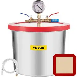
TECHNICAL PARAMETER
Model
T3
T5
Y2
T1.5
Volume
11L(3gal)
18L(5gal)
7L(2gal)
5.5L(1.5gal)
Product
size(mm)
φ230*270
φ280*300
210*200*180
φ230*160
Chamber
Material
304
304
Acrylic
304
Cover
Material
Temped
Glass
Temped Glass
Acrylic
Temped
Glass
Connecting
port of
gauge
1/4inchSAE
female
1/4inchSAE
female
1/4inchSAE
female
1/4inchSAE
female
The general information given in this specification is not binding .
- 5 -
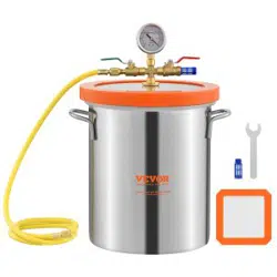
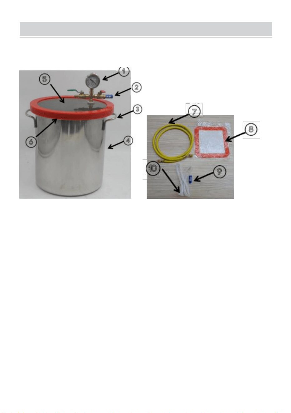
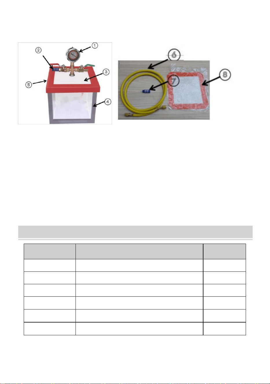
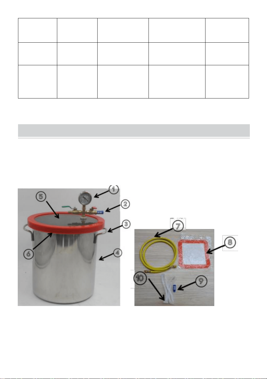
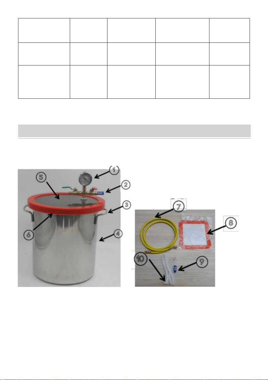
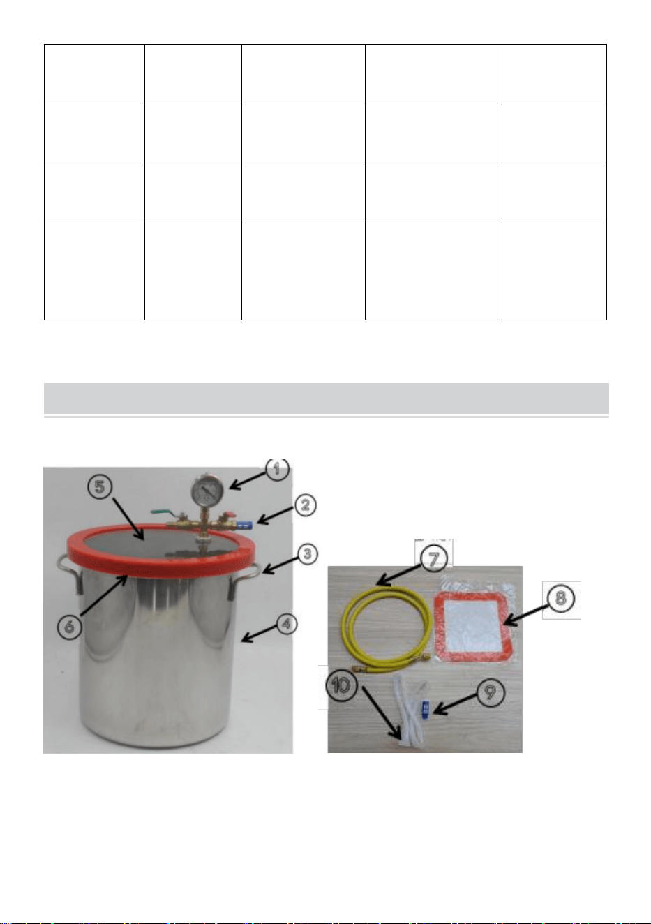
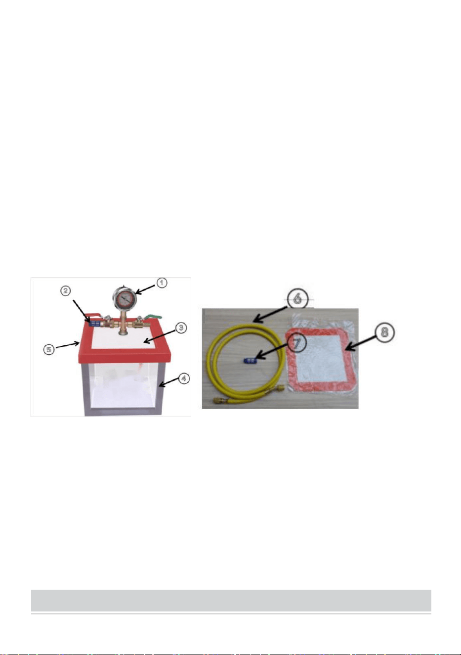
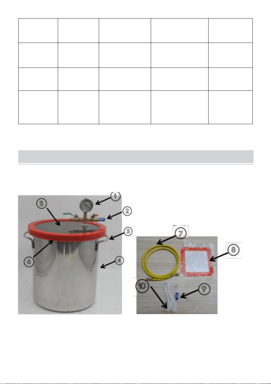
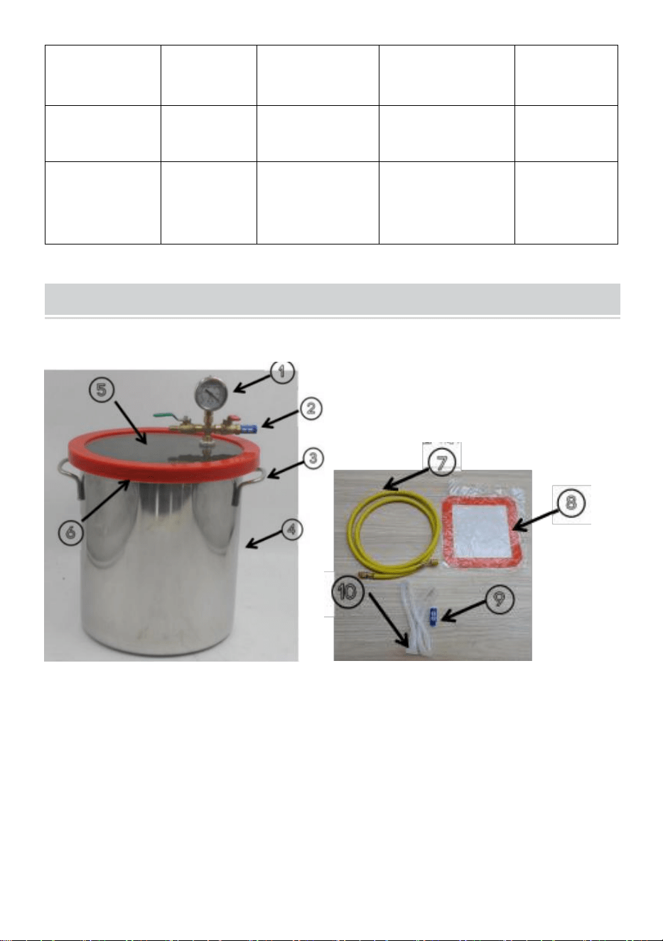
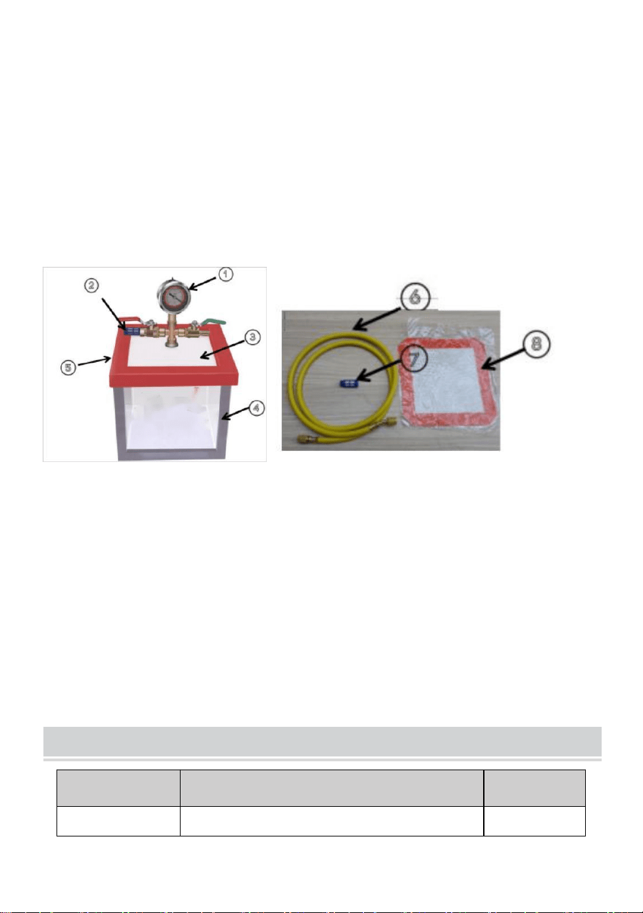
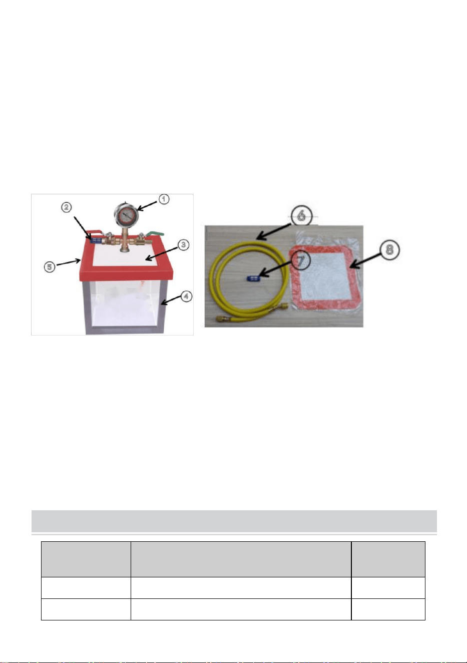
PRODUCT COMPOSITION
Composition of vacuum chamber components(
T3
、
T5
、
T1.5
)
1. Vacuum gauge
2. Silencer
3. Handle
4. Barrel body stainless steel
5. Tempered glass
6. Red rubber ring
7.1.5 beige rubber tube
8. Square gasket
9. One additional accessory silencer (complimentary)
10.White rubber ring (complimentary)
- 6 -
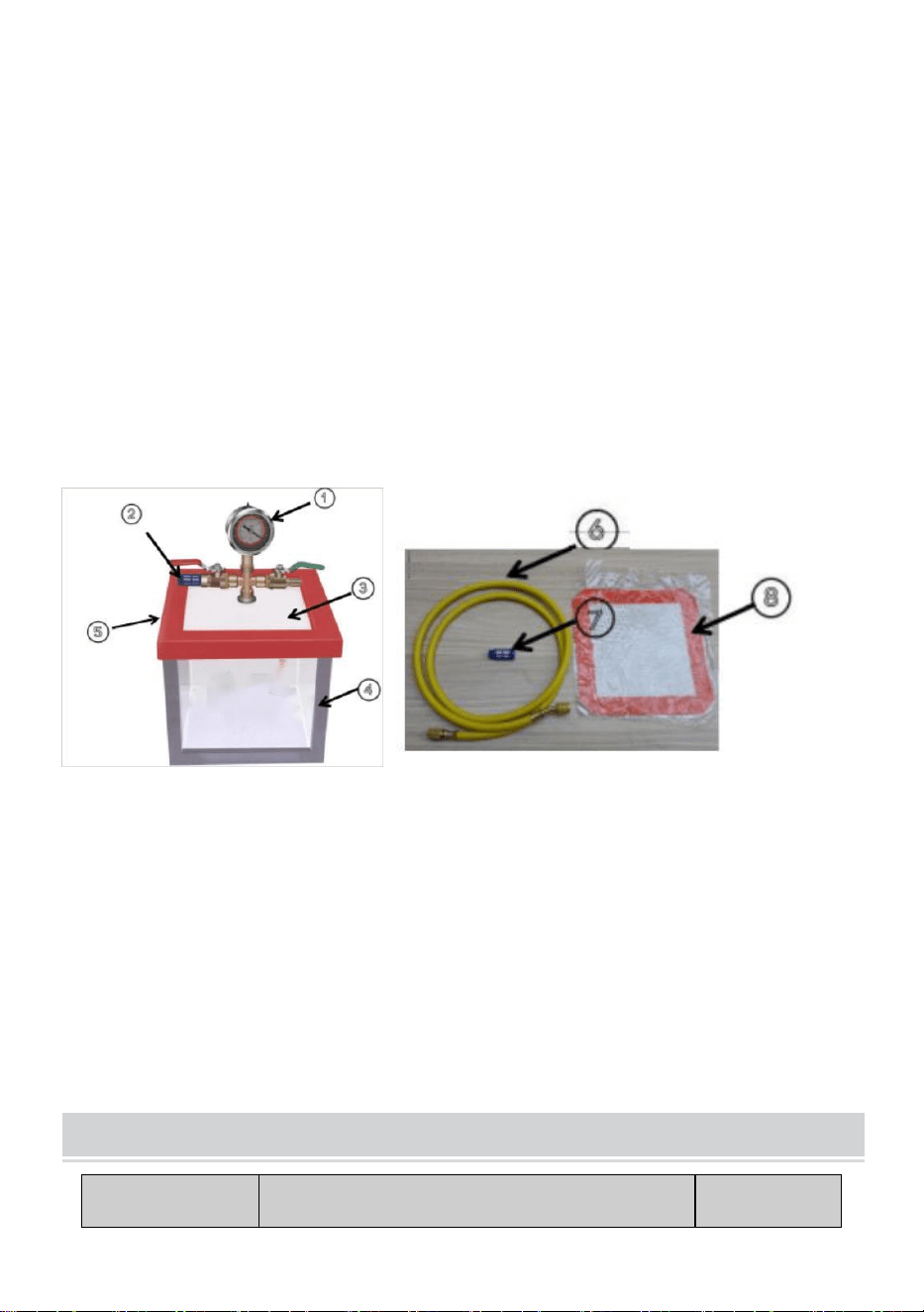
Composition of vacuum chamber components(
Y2
)
1. Vacuum gauge
2. Silencer
3. Acrylic cover plate
4. Barrel body acrylic
5. Square red rubber ring
6.1.5 beige rubber tube
7. One additional accessory silencer (complimentary)
8. Square gasket
STANDARD ACCESSORIES
PART NO.
DESCRIPTION
QTY
1
1.5 meter rubber tube (yellow)
1
2
White rubber ring (No include Y2)
1
3
Silencer
1
4
Square gasket
1
5
Vacuum gauge (No include Y2)
1
6
Wrench(No includd Y2)
1


- 8 -
Technique Certificat d'assistance et de garantie électronique
www.vevor.com/support
VIDE CHAMBRE
INSTRUCTIONS
MODÈLE : Y2/T3/T5/T1.5
We continue to be committed to provide you tools with competitive price.
"Save Half", "Half Price" or any other similar expressions used by us only represents an
estimate of savings you might benefit from buying certain tools with us compared to the major
top brands and does not necessarily mean to cover all categories of tools offered by us. You
are kindly reminded to verify carefully when you are placing an order with us if you are
actually saving half in comparison with the top major brands.
- 1 -
MODÈLE : Y2/T3/T5/T1.5
Have product questions? Need technical support? Please feel free to
contact us:
Technical Support and E-Warranty Certificate
www.vevor.com/support
NEED HELP? CONTACT US!
This is the original instruction, please read all manual instructions
carefully before operating. VEVOR reserves a clear interpretation of our
user manual. The appearance of the product shall be subject to the
product you received. Please forgive us that we won't inform you again if
there are any technology or software updates on our product.
VACUUM CHAMBER

- 2 -
IMPORTANT SAFEGUARDS
AVERTISSEMENT : Lisez ce document avant d'utiliser ce
produit. Le non-respect de cette consigne peut entraîner des
blessures graves.
Précautions de montage
1. Assemblez uniquement en suivant ces instructions. Un assemblage
incorrect peut créer des dangers.
2. Gardez la zone de montage propre et bien éclairée.
3. Gardez les spectateurs hors de la zone pendant l’assemblage.
4. Ne montez pas lorsque vous êtes fatigué ou sous l’influence de l’alcool,
de drogues ou de médicaments.
5. Les capacités du produit s'appliquent uniquement aux produits
correctement et complètement assemblés.
PRUDENCE :
1) Lorsque la jauge à vide du barillet à vide est connectée à la plaque
acrylique, des anneaux en caoutchouc doivent être installés sur le côtés
supérieur et inférieur, sinon, il y aura des fuites d'air.
2) Dans certains cas, la bague en caoutchouc rouge sur le bord extérieur
du couvercle de la chambre peut être irrégulière, ce qui entraîne une
mauvaise étanchéité lorsqu'elle est placée directement sur la chambre .
Cela peut entraîner l'absence de réponse de pression du manomètre à
vide. Pour résoudre ce problème, procédez comme suit :
f. Démarrer la pompe à vide.
g. À l’aide de vos deux mains, appuyez fermement sur le couvercle
de la chambre pendant environ 5 secondes.
h. Relâchez la pression sur le couvercle de la chambre après avoir
observé la rotation de l'aiguille sur la jauge à vide.
i. La rotation de l'aiguille de la jauge à vide indique que la chambre
à vide et la pompe à vide fonctionnent normalement.
- 3 -
j. En appliquant ce traitement, vous pouvez assurer une bonne
étanchéité et établir le fonctionnement normal de la chambre à
vide et de la pompe à vide.
Précautions d'emploi
AVERTISSEMENT : POUR ÉVITER TOUTE BLESSURE GRAVE
RÉSULTANT D'UN BASCULEMENT :
1. Ce produit n'est pas un jouet. Ne laissez pas les enfants jouer avec cet
article.
2. Utiliser uniquement comme prévu. Ne pas se tenir debout ou s'asseoir
sur le produit.
3. Assurez-vous que l'anneau en caoutchouc rouge n'est pas desserré
avant chaque utilisation.
CONSERVEZ CES INSTRUCTIONS
INSTRUCTIONS FOR VACUUM PUMP AND VACUUM CHAMBER
1. Après avoir retiré
l'ensemble de jauge à vide,
installez l'ensemble de jauge
à vide dans l'ordre indiqué
sur le schéma, puis serrez
l'écrou avec la force
appropriée.
2. Préparez 1 aspirateur
pompe , 1 aspirateur chambre et
pompe à vide huile .
- 4 -
3 . Après le remplissage le
vide pompe , connecter le
tuyau à l'air entrée ajutage
de le vide pompe .
4 . L'interface à le autre fin de le
tuyau est connecté avec le vide
jauge , et le soupape changer
est montré dans la figure .
5 . Après le connexion ,
démarrer le pouvoir
normalement , et tu peux voir
que le aiguille pression de le
vide jauge va tourner .
TECHNICAL PARAMETER
Modèle
T3
T5
Y2
T 1.5
Volume
11 L (3 gal)
18 L (5 gal)
7 L (2 gal)
5,5 L (1,5 gal)
Taille du
produit
(mm)
φ230*270
φ280*300
210*200*180
φ230*160
- 5 -
Matériau de
la chambre
304
304
Acrylique
304
Matériau de
couverture
Verre trempé
Verre trempé
Acrylique
Verre trempé
Port de
connexion
de la jauge
1/4 pouce
SAE femelle
1/4 pouce SAE
femelle
1/4 pouce SAE
femelle
1/4 pouce
SAE femelle
Les informations générales données dans cette spécification ne sont pas
contractuelles.
PRODUCT COMPOSITION
Composition des composants de la chambre à vide ( T 3 、 T5 、
T1.5 )
1. Jauge à vide
2. Silencieux
3. Poignée
4. Corps du canon en acier inoxydable

- 6 -
5. Verre trempé
6. Anneau en caoutchouc rouge
Chambre à air en caoutchouc beige 7.1.5
8. Joint carré
9. Un silencieux accessoire supplémentaire (gratuit)
10. Anneau en caoutchouc blanc (gratuit)
Composition des composants de la chambre à vide (
Y2
)
1. Jauge à vide
2. Silencieux
3. Plaque de recouvrement en acrylique
4. Corps du canon en acrylique
5. Anneau en caoutchouc carré rouge
Chambre à air en caoutchouc beige 6.1.5
7. Un silencieux accessoire supplémentaire (gratuit)
8. Joint carré
STANDARD ACCESSORIES

- 7 -
PIÈCE N°
DESCRIPTION
Qté
1
Tube en caoutchouc de 1,5 mètre
(jaune)
1
2
Anneau en caoutchouc blanc ( non
inclus Y2 )
1
3
Silencieux
1
4
Joint carré
1
5
Manomètre à vide ( Y2 non inclus )
1
6
Clé (Y2 non incluse)
1


- 9 -
Technisch Support und E-Garantie-Zertifikat
www.vevor.com/support
VAKUUM KAMMER
ANWEISUNGEN
MODELL: Y2/T3/T5/T1.5
We continue to be committed to provide you tools with competitive price.
"Save Half", "Half Price" or any other similar expressions used by us only represents an
estimate of savings you might benefit from buying certain tools with us compared to the major
top brands and does not necessarily mean to cover all categories of tools offered by us. You
are kindly reminded to verify carefully when you are placing an order with us if you are
actually saving half in comparison with the top major brands.

- 1 -
MODELL: Y2/T3/T5/T1.5
Have product questions? Need technical support? Please feel free to
contact us:
Technical Support and E-Warranty Certificate
www.vevor.com/support
NEED HELP? CONTACT US!
This is the original instruction, please read all manual instructions
carefully before operating. VEVOR reserves a clear interpretation of our
user manual. The appearance of the product shall be subject to the
product you received. Please forgive us that we won't inform you again if
there are any technology or software updates on our product.
VACUUM CHAMBER

- 2 -
IMPORTANT SAFEGUARDS
ACHTUNG: Lesen Sie diese Informationen, bevor Sie das
Produkt verwenden. Andernfalls kann es zu schweren
Verletzungen kommen.
Vorsichtsmaßnahmen bei der Montage
1. Führen Sie die Montage ausschließlich gemäß dieser Anleitung durch.
Eine unsachgemäße Montage kann zu Gefahren führen.
2. Halten Sie den Versammlungsbereich sauber und gut beleuchtet.
3. Halten Sie während der Montage unbeteiligte Zuschauer vom Bereich
fern.
4. Nicht montieren, wenn Sie müde sind oder unter dem Einfluss von
Alkohol, Drogen oder Medikamenten stehen.
5. Die Produkteigenschaften gelten nur für ordnungsgemäß und
vollständig montierte Produkte.
VORSICHT :
1) Wenn das Vakuummeter des Vakuumfasses mit der Acrylplatte
verbunden ist, müssen Gummiringe auf der Ober- und Unterseite, sonst
kommt es zu einem Luftleck.
2) In einigen Fällen kann der rote Gummiring am äußeren Rand der
Kammerabdeckung uneben sein, was zu einer schlechten Abdichtung führt,
wenn er direkt auf die Kammer gelegt wird . Dies kann dazu führen, dass
das Vakuummeter keine Druckreaktion anzeigt. Um dieses Problem zu
beheben, führen Sie die folgenden Schritte aus:
k. Starten Sie die Vakuumpumpe.
l. etwa 5 Sekunden lang fest auf den Kammerdeckel .
m. Lassen Sie den Druck auf der Kammerabdeckung ab , nachdem
Sie die Drehung des Zeigers auf dem Vakuummeter beobachtet
haben.
n. Die Drehung des Vakuummeterzeigers zeigt an, dass die
Vakuumkammer und die Vakuumpumpe normal funktionieren.
o. Durch diese Behandlung können Sie eine ordnungsgemäße
Abdichtung sicherstellen und den normalen Betrieb der
- 3 -
Vakuumkammer und der Vakuumpumpe sicherstellen.
Vorsichtsmaßnahmen treffen
WARNUNG: UM SCHWERE VERLETZUNGEN DURCH KIPPEN ZU
VERMEIDEN:
1. Dieses Produkt ist kein Spielzeug. Erlauben Sie Kindern nicht, mit
diesem Artikel zu spielen.
2. Nur bestimmungsgemäß verwenden. Nicht auf dem Produkt stehen
oder sitzen.
3. Stellen Sie vor jedem Gebrauch sicher, dass der rote Gummiring nicht
locker ist.
BEWAHREN SIE DIESE ANWEISUNGEN AUF
INSTRUCTIONS FOR VACUUM PUMP AND VACUUM CHAMBER
1.Nach dem Entfernen der
Vakuummeterbaugruppe
installieren Sie die
Vakuummeterbaugruppe in
der im Diagramm gezeigten
Reihenfolge und ziehen Sie
dann die Mutter mit der
entsprechenden Kraft fest.
2. Bereiten Sie 1 Vakuum vor
Pumpe , 1 Vakuum Kammer und
Vakuumpumpe Öl .

- 4 -
3 . Nach dem Füllen Die
Vakuum pumpe , verbinden
Die Schlauch Zu die Luft
Einlass Düse von Die
Vakuum Pumpe .
4. Die Schnittstelle bei Die
andere Ende von Die Schlauch
Ist verbunden mit Die Vakuum
Messgerät und Die Ventil
schalten Ist abgebildet in die
Abbildung .
5. Nach Die Verbindung ,
Start Die Leistung
normalerweise und du
kannst sehen Das Die Zeiger
Druck von Die Vakuum
Messgerät wird rotieren .
TECHNICAL PARAMETER
Modell
T3
T5
Y2
T 1,5
Volumen
11 l (3
Gallonen)
18 l (5
Gallonen)
7 l (2 Gallonen)
5,5 l (1,5
Gallonen)
Produktgröße
(mm)
φ230*270
φ280*300
210*200*180
φ230*160
- 5 -
Kammermaterial
304
304
Acryl
304
Bezugsmaterial
Gehärtetes
Glas
Gehärtetes
Glas
Acryl
Gehärtetes
Glas
Anschlussport
des Manometers
1/4 Zoll
SAE
weiblich
1/4 Zoll SAE
weiblich
1/4 Zoll SAE
weiblich
1/4 Zoll SAE
weiblich
Die in dieser Spezifikation enthaltenen allgemeinen Angaben sind
unverbindlich.
PRODUCT COMPOSITION
Zusammensetzung der Vakuumkammerkomponenten ( T3 , T5 ,
T1,5 )
1. Vakuummeter
2. Schalldämpfer
3. Griff
4. Fasskörper Edelstahl
5. Gehärtetes Glas
6. Roter Gummiring

- 6 -
7.1.5 beiger Gummischlauch
8. Quadratische Dichtung
9. Ein zusätzlicher Zubehörschalldämpfer (kostenlos)
10.Weißer Gummiring (kostenlos)
Zusammensetzung der Vakuumkammerkomponenten ( Y2 )
1. Vakuummeter
2. Schalldämpfer
3. Acryl-Abdeckplatte
4. Fasskörper Acryl
5. Quadratischer roter Gummiring
6.1.5 beiger Gummischlauch
7. Ein zusätzlicher Zubehörschalldämpfer (kostenlos)
8. Quadratische Dichtung
STANDARD ACCESSORIES
TEIL NR.
BESCHREIBUNG
Menge
1
1,5 Meter Gummischlauch (gelb)
1

- 7 -
2
Weißer Gummiring ( Y2 nicht
enthalten )
1
3
Schalldämpfer
1
4
Quadratische Dichtung
1
5
Vakuummeter ( Y2 nicht inbegriffen )
1
6
Schraubenschlüssel (Y2 nicht
enthalten)
1


- 9 -
Tecnico Supporto e certificato di garanzia elettronica
www.vevor.com/support
VUOTO CAMERA
ISTRUZIONI
MODELLO: Y2/T3/T5/T1.5
We continue to be committed to provide you tools with competitive price.
"Save Half", "Half Price" or any other similar expressions used by us only represents an
estimate of savings you might benefit from buying certain tools with us compared to the major
top brands and does not necessarily mean to cover all categories of tools offered by us. You
are kindly reminded to verify carefully when you are placing an order with us if you are
actually saving half in comparison with the top major brands.

- 1 -
MODELLO: Y2/T3/T5/T1.5
Have product questions? Need technical support? Please feel free to
contact us:
Technical Support and E-Warranty Certificate
www.vevor.com/support
NEED HELP? CONTACT US!
This is the original instruction, please read all manual instructions
carefully before operating. VEVOR reserves a clear interpretation of our
user manual. The appearance of the product shall be subject to the
product you received. Please forgive us that we won't inform you again if
there are any technology or software updates on our product.
VACUUM CHAMBER

- 2 -
IMPORTANT SAFEGUARDS
ATTENZIONE: leggere questo materiale prima di utilizzare
questo prodotto. La mancata osservanza di questa
precauzione può causare gravi lesioni.
Precauzioni di montaggio
1. Montare solo secondo queste istruzioni. Un montaggio improprio può
creare pericoli.
2. Mantenere l'area di assemblaggio pulita e ben illuminata.
3. Tenere gli astanti fuori dall'area durante l'assemblaggio.
4. Non riunirsi quando si è stanchi o sotto l'effetto di alcol, droghe o
farmaci.
5. Le capacità del prodotto si applicano solo ai prodotti correttamente e
completamente assemblati.
ATTENZIONE :
1) Quando il vacuometro del barilotto del vuoto è collegato alla piastra
acrilica, è necessario installare anelli di gomma sulla piastra. lati superiore
e inferiore, altrimenti si verificheranno perdite d'aria.
2) In alcuni casi, l'anello di gomma rosso sul bordo esterno del coperchio
della camera potrebbe essere irregolare, causando una scarsa tenuta
quando posizionato direttamente sulla camera . Ciò può comportare che il
misuratore del vuoto non mostri alcuna risposta alla pressione. Per
risolvere questo problema, segui questi passaggi:
p. Avviare la pompa per vuoto.
q. Utilizzando entrambe le mani, premere con decisione il coperchio
della camera per circa 5 secondi.
r. Rilasciare la pressione sul coperchio della camera dopo aver
osservato la rotazione della lancetta del vacuometro.
s. La rotazione dell'indicatore del vacuometro indica che la camera a
vuoto e la pompa a vuoto funzionano normalmente.
t. Applicando questo trattamento è possibile garantire una corretta
tenuta e ripristinare il normale funzionamento della camera a
vuoto e della pompa a vuoto.

- 3 -
Usare precauzioni
ATTENZIONE: PER EVITARE GRAVI LESIONI DOVUTE AL
RIBALTAMENTO:
1. Questo prodotto non è un giocattolo. Non permettere ai bambini di
giocare con questo articolo.
2. Utilizzare solo come previsto. Non stare in piedi o seduti sul prodotto.
3. Prima di ogni utilizzo, assicurarsi che l'anello di gomma rosso non sia
allentato.
SALVA QUESTE ISTRUZIONI
INSTRUCTIONS FOR VACUUM PUMP AND VACUUM CHAMBER
1. Dopo aver rimosso il
gruppo del vacuometro,
installarlo nell'ordine
mostrato nello schema,
quindi serrare il dado con la
forza adeguata.
2 . Preparare 1 vuoto pompa , 1
vuoto camera e pompa a vuoto
olio .

- 4 -
3 . Dopo il riempimento IL
vuoto pompa , collegare IL
tubo flessibile A l'aria
ingresso ugello Di IL vuoto
pompa .
4 . L'interfaccia a IL altro FINE Di
IL tubo flessibile È collegato con
IL vuoto calibro , e IL valvola
interruttore È mostrato in la
figura .
5 . Dopo IL collegamento ,
inizio IL energia
normalmente , e puoi Vedere
Quello IL puntatore pressione
Di IL vuoto misura ruoterà .
TECHNICAL PARAMETER
Modello
Tipo 3
Tipo 5
Anno2
Età 1.5
Volume
11L (3
galloni)
18L (5 galloni)
7L (2 galloni)
5,5 litri (1,5
galloni)
Dimensioni
del prodotto
φ230*270
φ280*300
Dimensioni:
210*200*180
φ230*160
- 5 -
(mm)
Materiale
della camera
304
304
Acrilico
304
Materiale di
copertura
Vetro
temperato
Vetro temperato
Acrilico
Vetro
temperato
Porta di
collegamento
del
misuratore
1/4 pollice
SAE
femmina
1/4 pollice SAE
femmina
1/4 pollice SAE
femmina
1/4 pollice
SAE femmina
Le informazioni generali fornite nella presente specifica non sono
vincolanti.
PRODUCT COMPOSITION
Composizione dei componenti della camera a vuoto ( T 3 , T5 , T1,5 )
1. Misuratore del vuoto
2. Silenziatore
3. Maniglia
- 6 -
4. Corpo della canna in acciaio inossidabile
5. Vetro temperato
6. Anello di gomma rossa
7.1.5 tubo di gomma beige
8. Guarnizione quadrata
9. Un silenziatore accessorio aggiuntivo (in omaggio)
10.Anello di gomma bianco (in omaggio)
Composizione dei componenti della camera a vuoto ( Y2 )
1. Misuratore del vuoto
2. Silenziatore
3. Piastra di copertura in acrilico
4. Corpo della canna in acrilico
5. Anello di gomma rosso quadrato
6.1.5 tubo di gomma beige
7. Un silenziatore accessorio aggiuntivo (in omaggio)
8. Guarnizione quadrata
STANDARD ACCESSORIES

- 7 -
N. PARTE
DESCRIZIONE
Quantità
1
Tubo di gomma da 1,5 metri (giallo)
1
2
Anello di gomma bianco ( non incluso
Y2 )
1
3
Silenziatore
1
4
Guarnizione quadrata
1
5
Misuratore del vuoto ( non incluso Y2 )
1
6
Chiave inglese (non inclusa Y2)
1


- 9 -
Técnico Certificado de soporte y garantía electrónica
www.vevor.com/support
VACÍO CÁMARA
INSTRUCCIONES
MODELO: Y2/T3/T5/T1.5
We continue to be committed to provide you tools with competitive price.
"Save Half", "Half Price" or any other similar expressions used by us only represents an
estimate of savings you might benefit from buying certain tools with us compared to the major
top brands and does not necessarily mean to cover all categories of tools offered by us. You
are kindly reminded to verify carefully when you are placing an order with us if you are
actually saving half in comparison with the top major brands.

- 1 -
MODELO: Y2/T3/T5/T1.5
Have product questions? Need technical support? Please feel free to
contact us:
Technical Support and E-Warranty Certificate
www.vevor.com/support
NEED HELP? CONTACT US!
This is the original instruction, please read all manual instructions
carefully before operating. VEVOR reserves a clear interpretation of our
user manual. The appearance of the product shall be subject to the
product you received. Please forgive us that we won't inform you again if
there are any technology or software updates on our product.
VACUUM CHAMBER

- 2 -
IMPORTANT SAFEGUARDS
ADVERTENCIA: Lea este material antes de utilizar este
producto. No hacerlo puede provocar lesiones graves.
Precauciones de montaje
1. Realice el montaje únicamente de acuerdo con estas instrucciones. Un
montaje inadecuado puede generar peligros.
2. Mantenga el área de reunión limpia y bien iluminada.
3. Mantenga a los transeúntes fuera del área durante el montaje.
4. No se reúna cuando esté cansado o bajo la influencia del alcohol,
drogas o medicamentos.
5. Las capacidades del producto se aplican únicamente a productos
ensamblados de forma correcta y completa.
PRECAUCIÓN :
1) Cuando el manómetro de vacío del barril de vacío está conectado con la
placa acrílica, se deben instalar anillos de goma en el lados superior e
inferior, de lo contrario, habrá fugas de aire.
2) En algunos casos, el anillo de goma rojo en el borde exterior de la tapa
de la cámara puede estar desparejo, lo que provoca un sellado deficiente
cuando se coloca directamente sobre la cámara . Esto puede provocar
que el manómetro de vacío no muestre respuesta de presión. Para
resolver este problema, siga estos pasos:
u. Ponga en marcha la bomba de vacío.
v. Con ambas manos, presione firmemente la tapa de la cámara
durante aproximadamente 5 segundos.
w. Libere la presión en la tapa de la cámara después de observar la
rotación del puntero en el manómetro de vacío.
x. La rotación del puntero del vacuómetro indica que la cámara de
vacío y la bomba de vacío están funcionando normalmente.
y. Aplicando este tratamiento se puede garantizar un correcto
sellado y establecer el funcionamiento normal de la cámara de
vacío y de la bomba de vacío.
- 3 -
Tome precauciones
ADVERTENCIA: PARA EVITAR LESIONES GRAVES POR VUELCO:
1. Este producto no es un juguete. No permita que los niños jueguen con
él.
2. Utilícelo únicamente para el fin previsto. No se pare ni se siente sobre el
producto.
3. Asegúrese de que el anillo de goma rojo no esté suelto antes de cada
uso.
GUARDE ESTAS INSTRUCCIONES
INSTRUCTIONS FOR VACUUM PUMP AND VACUUM CHAMBER
1. Después de quitar el
conjunto del medidor de
vacío, instálelo en el orden
que se muestra en el
diagrama y luego apriete la
tuerca con la fuerza
adecuada.
2. Preparar 1 aspiradora
bomba , 1 vacío cámara y
bomba de vacío aceite .

- 4 -
3 . Después del llenado el
vacío bomba , conectar el
manguera a El aire entrada
boquilla de el vacío
bomba .
4 . La interfaz en el otro fin de el
manguera es conectado con el
vacío calibre , y el válvula
cambiar es mostrado en la
figura .
5 . Después el conexión ,
inicio el fuerza
normalmente , y puede ver
eso el puntero presión de el
vacío indicador girará .
TECHNICAL PARAMETER
Modelo
T3
T5
Año 2
T1.5
Volumen
11L (3
galones)
18L (5 galones)
7L (2 galones)
5,5 l (1,5
galones)
Tamaño del
producto
φ230*270
φ280*300
210*200*180
φ230*160
- 5 -
(mm)
Material de
la cámara
304
304
Acrílico
304
Material de
la cubierta
Vidrio
templado
Vidrio templado
Acrílico
Vidrio
templado
Puerto de
conexión del
medidor
SAE hembra
de 1/4
pulgada
SAE hembra de
1/4 pulgada
SAE hembra de
1/4 pulgada
SAE hembra
de 1/4
pulgada
La información general proporcionada en esta especificación no es
vinculante.
PRODUCT COMPOSITION
Composición de los componentes
de
la cámara de vacío (
T3 , T5 ,
T1,5
)
1. Vacuómetro
2. Silenciador
3. Manejar

- 6 -
4. Cuerpo del cañón de acero inoxidable.
5. Vidrio templado
6. Anillo de goma rojo
7.1.5 tubo de goma beige
8. Junta cuadrada
9. Un silenciador adicional (de cortesía)
10. Anillo de goma blanco (de cortesía)
Composición de los componentes de la cámara de vacío ( Y2 )
1. Vacuómetro
2. Silenciador
3. Placa de cubierta de acrílico
4. Cuerpo del cañón acrílico
5. Anillo de goma cuadrado rojo
6.1.5 tubo de goma beige
7. Un silenciador adicional (de cortesía)
8. Junta cuadrada
STANDARD ACCESSORIES
- 7 -
NÚMERO DE
PIEZA
DESCRIPCIÓN
CANTIDA
D
1
Tubo de goma de 1,5 metros
(amarillo)
1
2
Anillo de goma blanco ( no incluye
Y2 )
1
3
Silenciador
1
4
Junta cuadrada
1
5
Manómetro de vacío ( no incluye Y2 )
1
6
Llave (no incluida Y2)
1


- 9 -
Techniczny Wsparcie i certyfikat e-gwarancji
www.vevor.com/support
PRÓŻNIA IZBA
INSTRUKCJE
MODELE: Y2/T3/T5/T1.5
We continue to be committed to provide you tools with competitive price.
"Save Half", "Half Price" or any other similar expressions used by us only represents an
estimate of savings you might benefit from buying certain tools with us compared to the major
top brands and does not necessarily mean to cover all categories of tools offered by us. You
are kindly reminded to verify carefully when you are placing an order with us if you are
actually saving half in comparison with the top major brands.

- 1 -
MODELE: Y2/T3/T5/T1.5
Have product questions? Need technical support? Please feel free to
contact us:
Technical Support and E-Warranty Certificate
www.vevor.com/support
NEED HELP? CONTACT US!
This is the original instruction, please read all manual instructions
carefully before operating. VEVOR reserves a clear interpretation of our
user manual. The appearance of the product shall be subject to the
product you received. Please forgive us that we won't inform you again if
there are any technology or software updates on our product.
VACUUM CHAMBER

- 2 -
IMPORTANT SAFEGUARDS
OSTRZEŻENIE: Przeczytaj ten materiał przed użyciem tego
produktu. Niedopełnienie tego obowiązku może spowodować
poważne obrażenia.
Środki ostrożności podczas montażu
1. Montaż należy wykonywać wyłącznie zgodnie z niniejszą instrukcją.
Nieprawidłowy montaż może stwarzać zagrożenia.
2. Utrzymuj miejsce zgromadzenia w czystości i zapewnij dobre
oświetlenie.
3. Podczas montażu nie dopuszczać osób postronnych na teren montażu.
4. Nie przychodź na spotkania, jeśli jesteś zmęczony lub pod wpływem
alkoholu, narkotyków lub leków.
5. Możliwości produktu odnoszą się wyłącznie do produktów prawidłowo i
kompletnie zmontowanych.
OSTROŻNOŚĆ :
1) Po połączeniu manometru próżniowego lufy z płytą akrylową należy na
niej zamontować pierścienie gumowe. górną i dolną stronę, w przeciwnym
razie będzie dochodziło do nieszczelności.
2) W niektórych przypadkach czerwony gumowy pierścień na zewnętrznej
krawędzi pokrywy komory może być nierówny, co powoduje słabe
uszczelnienie po umieszczeniu go bezpośrednio na komorze . Może to
spowodować, że wskaźnik podciśnienia nie będzie reagował na ciśnienie.
Aby rozwiązać ten problem, wykonaj następujące czynności:
z. Uruchom pompę próżniową.
aa. Mocno naciśnij pokrywę komory obiema rękami i przytrzymaj ją
przez około 5 sekund.
ab. Zwolnij nacisk na pokrywę komory po zaobserwowaniu obrotu
wskazówki na wskaźniku próżni.
ac. Obrót wskazówki manometru próżniowego oznacza, że komora
próżniowa i pompa próżniowa działają prawidłowo.
ad. Dzięki zastosowaniu tego zabiegu można zapewnić odpowiednie

- 3 -
uszczelnienie i przywrócić normalną pracę komory próżniowej
oraz pompy próżniowej.
Stosuj środki ostrożności
OSTRZEŻENIE: ABY UNIKNĄĆ POWAŻNYCH OBRAŻEŃ
SPOWODOWANYCH PRZEWRÓCENIEM:
1. Ten produkt nie jest zabawką. Nie pozwalaj dzieciom bawić się tym
przedmiotem.
2. Używać wyłącznie zgodnie z przeznaczeniem. Nie stawać ani nie siadać
na produkcie.
3. Przed każdym użyciem upewnij się, że czerwony gumowy pierścień nie
jest luźny.
ZAPISZ TE INSTRUKCJE
INSTRUCTIONS FOR VACUUM PUMP AND VACUUM CHAMBER
1. Po wyjęciu zespołu
wskaźnika podciśnienia
zamontuj zespół wskaźnika
podciśnienia w kolejności
pokazanej na schemacie, a
następnie dokręć nakrętkę z
odpowiednią siłą.
2. Przygotuj 1 odkurzacz
pompa , 1 próżnia komora i
pompa próżniowa olej .

- 4 -
3 . Po napełnieniu ten
próżnia pompa , podłącz
ten wąż gumowy Do
powietrze wlot dysza z ten
próżnia pompa .
4. Interfejs w ten Inny koniec z
ten wąż gumowy Jest połączony
z ten próżnia wskaźnik i ten
zawór przełącznik Jest
pokazano w figura .
5. Po ten połączenie ,
start ten moc normalnie i
możesz Widzieć To ten
wskaźnik ciśnienie z ten
próżnia miernik będzie się
obracać .
TECHNICAL PARAMETER
Model
T3
T5
Y2
T1.5
Tom
11L (3
galony)
18L (5
galonów)
7L (2 galony)
5,5 l (1,5
galona)
Rozmiar
produktu (mm)
φ230*270
φ280*300
210*200*180
φ230*160
- 5 -
Materiał
komory
304
304
Akryl
304
Materiał na
okładkę
Szkło
hartowane
Szkło
hartowane
Akryl
Szkło
hartowane
Port
przyłączeniowy
wskaźnika
1/4 cala
SAE żeński
1/4 cala SAE
żeński
1/4 cala SAE żeń
ski
1/4 cala SAE
żeński
niniejszej specyfikacji nie są wiążące.
PRODUCT COMPOSITION
Skład komponentów komory próżniowej ( T 3 , T5 , T1.5 )
1. Wskaźnik próżni
2. Tłumik
3. Uchwyt
4. Korpus lufy ze stali nierdzewnej
5. Szkło hartowane
6. Czerwony gumowy pierścień
7.1.5 beżowa gumowa rurka
8. Uszczelka kwadratowa
- 6 -
9. Jeden dodatkowy tłumik akcesoryjny (bezpłatny)
10.Biały gumowy pierścień (bezpłatnie)
Skład komponentów komory próżniowej ( Y2 )
1. Wskaźnik próżni
2. Tłumik
3. Płyta osłonowa akrylowa
4. Korpus lufy akrylowy
5. Kwadratowy czerwony gumowy pierścień
6.1.5 beżowa gumowa rurka
7. Jeden dodatkowy tłumik akcesoryjny (bezpłatny)
8. Uszczelka kwadratowa
STANDARD ACCESSORIES
NR CZĘŚCI
OPIS
ILOŚĆ
1
Rurka gumowa 1,5 metra (żółta)
1

- 7 -
2
Biały gumowy pierścień ( brak w
zestawie Y2 )
1
3
Tłumik
1
4
Uszczelka kwadratowa
1
5
Wskaźnik podciśnienia ( bez Y2 )
1
6
Klucz (nie zawiera Y2)
1


- 9 -
Technisch Ondersteuning en E-garantiecertificaat
www.vevor.com/support
VACUÜM KAMER
INSTRUCTIES
MODEL: Y2/T3/T5/T1.5
We continue to be committed to provide you tools with competitive price.
"Save Half", "Half Price" or any other similar expressions used by us only represents an
estimate of savings you might benefit from buying certain tools with us compared to the major
top brands and does not necessarily mean to cover all categories of tools offered by us. You
are kindly reminded to verify carefully when you are placing an order with us if you are
actually saving half in comparison with the top major brands.

- 1 -
MODEL: Y2/T3/T5/T1.5
Have product questions? Need technical support? Please feel free to
contact us:
Technical Support and E-Warranty Certificate
www.vevor.com/support
NEED HELP? CONTACT US!
This is the original instruction, please read all manual instructions
carefully before operating. VEVOR reserves a clear interpretation of our
user manual. The appearance of the product shall be subject to the
product you received. Please forgive us that we won't inform you again if
there are any technology or software updates on our product.
VACUUM CHAMBER

- 2 -
IMPORTANT SAFEGUARDS
WAARSCHUWING: Lees dit materiaal voordat u dit product
gebruikt. Als u dit niet doet, kan dit leiden tot ernstig letsel.
Voorzorgsmaatregelen bij de montage
1. Monteer alleen volgens deze instructies. Onjuiste montage kan gevaren
opleveren.
2. Zorg dat de verzamelplaats schoon en goed verlicht is.
3. Houd omstanders uit de buurt tijdens de montage.
4. Kom niet bijeen als u moe bent of onder invloed van alcohol, drugs of
medicijnen.
5. De producteigenschappen gelden alleen voor correct en volledig
gemonteerde producten.
VOORZICHTIGHEID :
1) Wanneer de vacuümmeter van het vacuümvat is verbonden met de
acrylplaat, moeten er rubberen ringen op de boven- en onderkant, anders
kan er lucht ontsnappen.
2) In sommige gevallen kan de rode rubberen ring aan de buitenrand van
de kamerdeksel ongelijk zijn, wat een slechte afdichting veroorzaakt
wanneer deze direct op de kamer wordt geplaatst . Dit kan ertoe leiden dat
de vacuümmeter geen drukrespons weergeeft. Volg deze stappen om dit
probleem op te lossen:
ae. Start de vacuümpomp.
af. Druk met beide handen ongeveer 5 seconden lang stevig op het
deksel van de kamer .
ag. Laat de druk op het kamerdeksel los nadat u de rotatie van de
wijzer op de vacuümmeter hebt geobserveerd.
ah. De rotatie van de wijzer van de vacuümmeter geeft aan dat de
vacuümkamer en de vacuümpomp normaal werken.
ai. Door deze behandeling toe te passen, kunt u een goede
afdichting garanderen en de normale werking van de
vacuümkamer en vacuümpomp herstellen.
- 3 -
Neem voorzorgsmaatregelen
WAARSCHUWING: OM ERNSTIG LETSEL DOOR KANTELEN TE
VOORKOMEN:
1. Dit product is geen speelgoed. Laat kinderen niet met dit artikel spelen.
2. Gebruik alleen zoals bedoeld. Ga niet op het product staan of zitten.
3. Controleer voor elk gebruik of de rode rubberen ring niet los zit.
BEWAAR DEZE INSTRUCTIES
INSTRUCTIONS FOR VACUUM PUMP AND VACUUM CHAMBER
1. Nadat u de
vacuümmeter-eenheid hebt
verwijderd, installeert u de
vacuümmeter-eenheid in de
volgorde zoals aangegeven
in het diagram. Draai
vervolgens de moer vast met
de juiste kracht.
2. Bereid 1 vacuüm voor
pomp , 1 vacuüm kamer en
vacuümpomp olie .

- 4 -
3 . Na het vullen de
vacuüm pomp , aansluiten
de slang naar de lucht
inlaat mondstuk van de
vacuüm pomp .
4. De interface op de ander
einde van de slang is verbonden
met de vacuüm meter , en de
ventiel schakelaar is getoond in
het figuur .
5. Na de verbinding , start
de stroom normaal
gesproken , en jij kan zien
Dat de wijzer druk van de
vacuüm graadmeter zal
roteren .
TECHNICAL PARAMETER
Model
T3
T5
Jaar 2
T1.5
Volume
11L (3 gal)
18L (5 gal)
7L (2 gal)
5,5 liter (1,5
gal)
Productgrootte
(mm)
φ230*270
φ280*300
210*200*180
φ230*160

- 5 -
Kamermateriaal
304
304
Acryl
304
Materiaal van
de omslag
Gehard
glas
Gehard glas
Acryl
Gehard glas
Aansluitpoort
van de meter
1/4inchSAE
vrouwelijk
1/4inchSAE
vrouwelijk
1/4inchSAE
vrouwelijk
1/4inchSAE
vrouwelijk
De algemene informatie in deze specificatie is niet bindend.
PRODUCT COMPOSITION
Samenstelling van vacuümkamercomponenten ( T 3 , T5 , T1.5 )
1. Vacuümmeter
2. Geluiddemper
3. Handvat
4. Vatlichaam roestvrij staal
5. Gehard glas
6. Rode rubberen ring
7.1.5 beige rubberen buis
8. Vierkante pakking
- 6 -
9. Eén extra accessoire-demper (gratis)
10. Witte rubberen ring (gratis)
Samenstelling van vacuümkamercomponenten ( Y2 )
1. Vacuümmeter
2. Geluiddemper
3. Acryl afdekplaat
4. Vatlichaam van acryl
5. Vierkante rode rubberen ring
6.1.5 beige rubberen buis
7. Eén extra accessoire-demper (gratis)
8. Vierkante pakking
STANDARD ACCESSORIES
ONDERDEEL
NR.
BESCHRIJVING
Hoeveelhe
id
1
1,5 meter rubberen slang (geel)
1
2
Witte rubberen ring ( geen Y2
1

- 7 -
inbegrepen )
3
Geluiddemper
1
4
Vierkante pakking
1
5
Vacuümmeter ( geen Y2 inbegrepen )
1
6
Moersleutel (niet inbegrepen Y2)
1


- 9 -
Teknisk Support och e-garanticertifikat
www.vevor.com/support
VAKUUM KAMMARE
INSTRUKTIONER
MODELL: Y2/T3/T5/T1.5
We continue to be committed to provide you tools with competitive price.
"Save Half", "Half Price" or any other similar expressions used by us only represents an
estimate of savings you might benefit from buying certain tools with us compared to the major
top brands and does not necessarily mean to cover all categories of tools offered by us. You
are kindly reminded to verify carefully when you are placing an order with us if you are
actually saving half in comparison with the top major brands.

- 1 -
MODELL: Y2/T3/T5/T1.5
Have product questions? Need technical support? Please feel free to
contact us:
Technical Support and E-Warranty Certificate
www.vevor.com/support
NEED HELP? CONTACT US!
This is the original instruction, please read all manual instructions
carefully before operating. VEVOR reserves a clear interpretation of our
user manual. The appearance of the product shall be subject to the
product you received. Please forgive us that we won't inform you again if
there are any technology or software updates on our product.
VACUUM CHAMBER

- 2 -
IMPORTANT SAFEGUARDS
VARNING: Läs detta material innan du använder denna
produkt. Underlåtenhet att göra det kan resultera i allvarliga
skador.
Försiktighetsåtgärder vid montering
1. Montera endast enligt dessa instruktioner. Felaktig montering kan skapa
faror.
2 . Håll monteringsområdet rent och väl upplyst.
3 . Håll åskådare borta från området under monteringen.
4 . Sätt dig inte ihop när du är trött eller påverkad av alkohol, droger eller
mediciner.
5 . Produktegenskaperna gäller endast för korrekt och färdigmonterade
produkter.
FÖRSIKTIGHET:
1) När vakuummätaren på vakuumröret är ansluten till akrylplattan måste
gummiringar installeras på övre och nedre sidorna, annars kommer det att
finnas luftläckage.
2) I vissa fall kan den röda gummiringen på ytterkanten av kammarlocket
vara ojämn, vilket orsakar dålig tätning när den placeras direkt på
kammaren . Detta kan resultera i att vakuummätaren inte visar något
trycksvar. Följ dessa steg för att lösa problemet:
aj. Starta vakuumpumpen.
ak. Använd båda händerna och tryck bestämt ned kammarlocket i
cirka 5 sekunder.
al. Släpp trycket på kammarlocket efter att ha observerat rotationen
av visaren på vakuummätaren.
am. Vridningen av vakuummätaren visar att vakuumkammaren och
vakuumpumpen fungerar normalt.
an. Genom att tillämpa denna behandling kan du säkerställa korrekt
tätning och etablera normal drift av vakuumkammaren och
vakuumpumpen.
Använd försiktighetsåtgärder
- 3 -
VARNING: FÖR ATT FÖRHINDRA ALLVARLIG SKADA VID VÄTTNING:
1. Denna produkt är inte en leksak. Tillåt inte barn att leka med detta
föremål.
2. Använd endast på avsett sätt. Stå eller sitt inte på produkten.
3. Se till att den röda gummiringen inte är lös före varje användning.
SPARA DESSA INSTRUKTIONER
INSTRUCTIONS FOR VACUUM PUMP AND VACUUM CHAMBER
1. Efter att ha tagit bort
vakuummätarenheten,
installera
vakuummätarenheten i den
ordning som visas i
diagrammet och dra sedan åt
muttern med lämplig kraft.
2 . Förbered 1 vakuum pump , 1
vakuum kammare och
vakuumpump olja .

- 4 -
3 . Efter påfyllning de
vakuum pump , anslut de
slang till luften inlopp
munstycke av de vakuum
pump .
4 . Gränssnittet på de andra
avsluta av de slang är kopplat till
de vakuum mätare och de
ventil växla är visas i
figuren .
5 . Efter de anslutning ,
starta de driva normalt , och
du kan se att de pekare tryck
av de vakuum spårvidd
kommer att rotera .
TECHNICAL PARAMETER
M odel
T3
T5
Y2
T 1,5
Volym
11L(3gal)
18L (5gal)
7L (2gal)
5,5 L (1,5
gal)
Produktstorlek
(mm)
φ230*270
φ280*300
210*200*180
φ230*160
- 5 -
Kammarmaterial
304
304
Akryl
304
Täckmaterial
Temperat
glas
Temperat glas
Akryl
Temperat
glas
Anslutningsport
för mätare
1/4 tum
SAE hona
1/4 tum SAE
hona
1/4 tum SAE
hona
1/4 tum SAE
hona
Den allmänna informationen i denna specifikation är inte bindande.
PRODUCT COMPOSITION
Sammansättning av komponenter i vakuumkammaren ( T 3 、 T5 、
T1.5 )
1. Vakuummätare
2. Ljuddämpare
3. Handtag
4. Fatkropp i rostfritt stål
5. Härdat glas
6. Röd gummiring
- 6 -
7.1.5 beige gummislang
8. Fyrkantig packning
9. Ytterligare en ljuddämpare (gratis)
10. Vit gummiring (gratis)
Sammansättning av komponenter i vakuumkammaren ( Y2 )
1. Vakuummätare
2. Ljuddämpare
3. Akryl täckplåt
4. Fatkropp akryl
5. Fyrkantig röd gummiring
6.1.5 beige gummislang
7. En extra ljuddämpare (gratis)
8. Fyrkantig packning
STANDARD ACCESSORIES
DELNR.
BESKRIVNING
ANTAL

- 7 -
1
1,5 meter gummislang (gul)
1
2
Vit gummiring ( Inkluderar ej Y2 )
1
3
Ljuddämpare
1
4
Fyrkantig packning
1
5
Vakuummätare ( Inkluderar ej Y2 )
1
6
Skiftnyckel (ingår ej Y2)
1