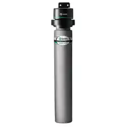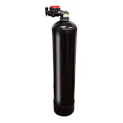
City Water Filter with Scale Control Media
For Models:
• FC1000

TABLE OF CONTENTS
Installation ........................................................................3
Startup Instructions ................................................................5
Replacement Parts .................................................................6
Installation Fitting Assemblies .......................................................7
Warranty ..........................................................................9
Quick Reference Guide .............................................................11
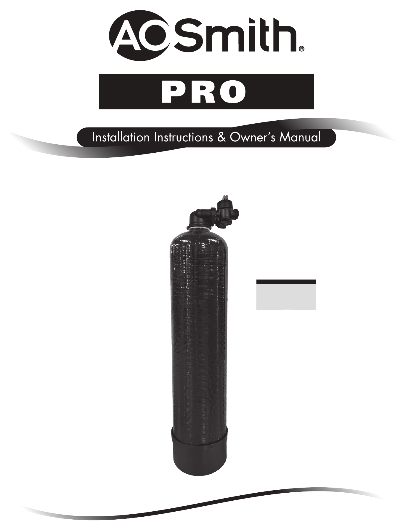
Your A. O. Smith Pro Series water filter is a precision built, high quality product. These units will deliver filtered water for many
years to come when installed and operated properly. Please study this manual carefully and understand the cautions and
notes before installing. This manual should be kept for future reference. If you have any questions regarding your water filter,
contact your local dealer.
PRODUCT INFORMATION
MODEL NUMBER
SERIAL NUMBER
DEALER INFORMATION:
3
GENERAL INSTALLATION & SERVICE WARNINGS
The control valve, fittings and/or bypass are designed to accommodate minor plumbing misalignments. There is a small amount of “give” to properly
connect the piping, but the water treatment unit is not designed to support the weight of the plumbing.
Do not use Vaseline, oils, other hydrocarbon lubricants, or spray silicone anywhere. A silicone lubricant may be used on black “O” Rings, but is not
necessary. Avoid any type of lubricants, including silicone, on red or clear lip seals.
Do not use pipe dope or other sealants on threads. Teflon® tape must be used on the threads of the 1” NPT inlet and outlet and on the threads for
the drain line connection. Teflon® tape is not used on the nut connections or caps because “O” Ring seals are used. The nuts and caps are designed
to be unscrewed or tightened by hand or with the special plastic Service Wrench, #100249864 (CV3193-02). If necessary, pliers can be used to
unscrew the nut or cap. Do not use a pipe wrench to tighten nuts or caps. Do not place screwdriver in slots on caps and/or tap with a hammer.
SITE REQUIREMENTS
• One Water Conditioner to Filter
• Water Pressure – 25-100 psi
• Water Temperature – 40-100°F (0.5-37.7°C)
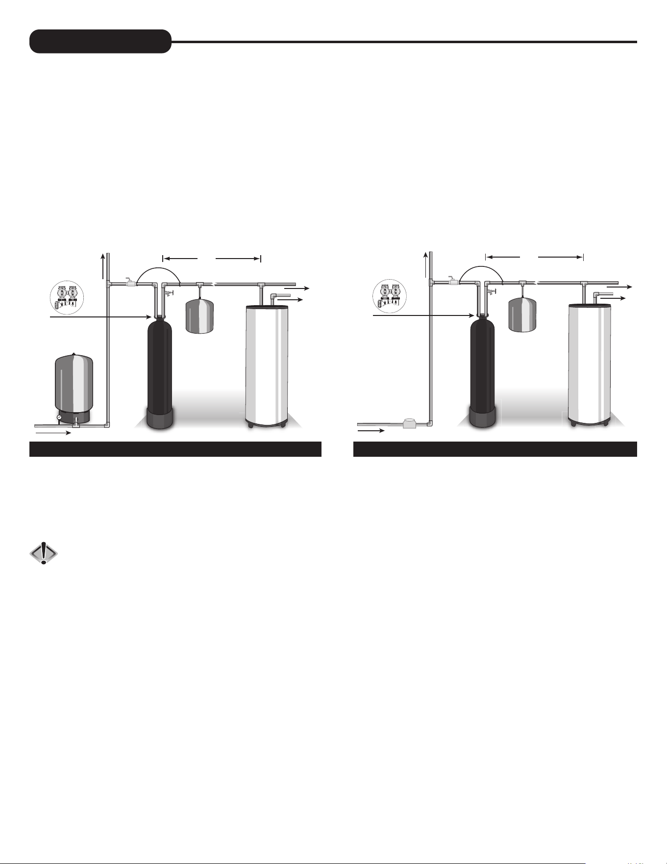
INSTALLATION
1. The distance between the drain and the water conditioner should be as short as possible (see #8).
2. The media tank should be installed on a firm, level surface (above or below grade).
3. It is NOT recommended to install any water treatment unit with less than 10 feet of piping between its outlet and the inlet of a water heater.
CAUTION: To protect the unit in the event of a hot water heater backup, the manufacturer recommends the use of an expansion tank
on the outlet side of the unit (see diagram).
4. Do not locate unit where it or its connections (including the drain and overflow lines) will ever be subjected to temperatures under 33°F.
5. Do not subject the tank to any vacuum as this may cause an “implosion” and could result in leaking. If there is a possibility a vacuum could
occur, please make provision for a vacuum breaker in the installation.
6. INLET/OUTLET PLUMBING: Be sure to install Bypass Valve onto main control valve before beginning plumbing. If it is desired to
bypass outside hydrants, a cold water kitchen sink, or other locations, provisions should be made at this time. Install an inlet shutoff
valve and plumb to the unit’s bypass valve inlet located at the right rear as you face the unit. There are a variety of installation fittings
available. They are listed under the Installation Fitting Assemblies section of the manual. When assembling the installation fitting package
(inlet and outlet), connect the fitting to the plumbing system first and then attach the nut, split ring and “O” Ring. Heat from soldering
or solvent cements may damage the nut, split ring or “O” Ring. Solder joints should be cool and solvent cements should be set before
installing the nut, split ring and “O” Ring. Avoid getting solder flux, primer, and solvent cement on any part of the “O” Rings, split rings, bypass
valve or control valve. If the building’s electrical system is grounded to the plumbing, install a copper grounding strap from the inlet to the outlet
pipe. Plumbing must be done in accordance with all applicable local codes.
COLD
HOT
EXPANSION
TANK
SHUTOFF
VA LV E
MAY NOT
BE REQUIRED
GROUND
STRAP
10 FEET
OUTSIDE TA P
WATER SUPPLY
BOILER
DRAIN
WATER
HEATER
PRESSURE
TANK
O
V
E
R
H
E
A
D
V
I
E
W
O
F
B
Y
P
A
S
S
V
A
L
V
E
COLD
HOT
EXPANSION
TANK
SHUTOFF
VA LV E
MAY NOT
BE REQUIRED
GROUND
STRAP
10 FEET
OUTSIDE TA P
WATER SUPPLY
BOILER
DRAIN
WATER
HEATER
O
V
E
R
H
E
A
D
V
I
E
W
O
F
B
Y
P
A
S
S
V
A
L
V
E
WATER
METER
WELL WATER INSTALLATION MUNICIPAL INSTALLATION

4
INSTALLATION
Provisions should be made to bypass outside hydrants that are not to have filtered water. It is also advisable to install hose bibs on the inlet
and outside of the filter for future testing and service of the equipment. Where heavy sediment from the well is observed, it is advisable
to install a cartridge or bag-style filter immediately upstream from the filter. A nominal micron rating of 50 to 100 is recommended. The
purpose of this is to protect the control valve of any debris from the incoming water supply. If desired, a cartridge filter may be used after
the system as a polishing filter.
7. INSTALLING GROUND: To maintain an electrical ground in metal plumbing of a home’s cold water piping
(such as a copper plumbing system), install a ground clamp or jumper wiring.
NOTE: If replacing an existing unit, also replace the ground clamps/wire. If removing a unit, replace the
piping with the same type of piping as the original to assure plumbing integrity and grounding.
SHUTOFF
VA LV E
GROUND
STRAP
GROUND STRAP
4 5
STARTUP INSTRUCTIONS
OPERATION
The FC-1000 City Water Filter requires no backwashing and eliminates the need for a control valve and the extra water needed to regenerate.
The unit is equipped with an upper strainer assembly to prevent mineral loss. Please contact A. O. Smith with any ques ons pertaining to the
FC-1000 installa on.
OPERATING LIMITS
The unit is designed to func on with minimum water pressures of 20 psi, maximum water pressures of 100 psi, and a maximum water
temperature of 100 degrees F.
WATER QUALITY CONDITIONS
For the carbon and scale control media to be eff ec ve, incoming water must be clear, sediment free, with iron less than 0.3 ppm, pH less than
8.3, and hardness below 15gpg.
IN AND OUT VALVE
1. CAUTION: Ensure the In and Out Valve is ght on top of the tank. DO NOT over ghten.
2. Locate the bypass valve assembly that is packaged with the system. The bypass valve has two red handles that allow you to bypass
the unit, two threaded connec ons for the tail piece kit and two O-ring seal connec ons with nuts for the In and Out Valve. Align the
insert connec on ends with O-rings and nuts to the inlet and outlet connec ons of the control valve. Hand ghten the nuts.
3. Locate and assemble the tail piece kit. Align tail piece assembly to the bypass valve threaded inlet and insert un l the nut can be
ghtened. Hand ghten the nuts.
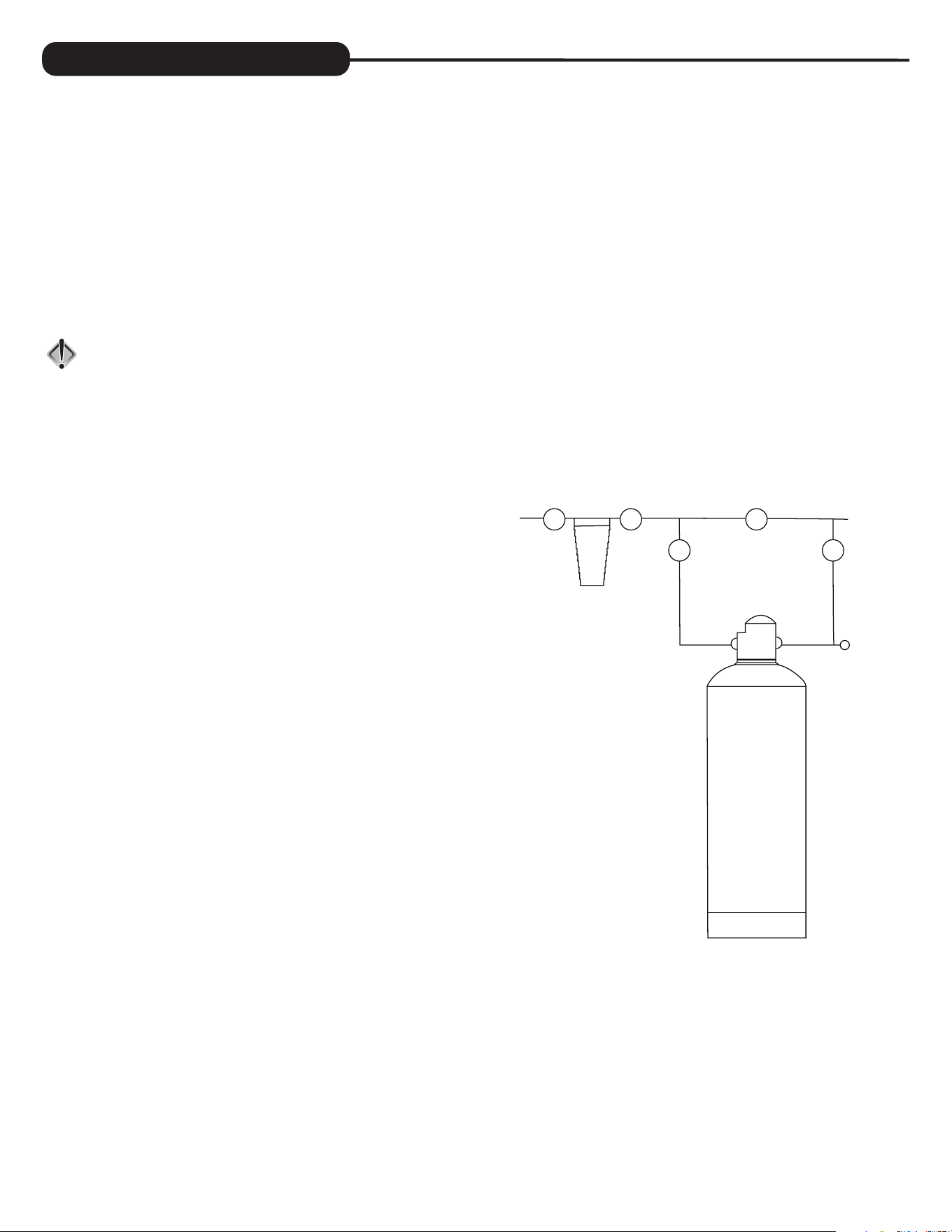
SERVICE LINE PIPING
1. Keep unit far enough away from walls and other obstruc ons to allow
for servicing the unit. Pipe water fi lter into the service lines. Plumb
the inlet plumbing into the UPFLOW INLET port of the in-out valve.
Plumb the outlet plumbing into the DOWNFLOW INLET port of the
in-out valve. Plumbing the unit for UPFLOW confi gura on will prevent
channeling of the media bed. Always follow local plumbing codes
when installing our water treatment equipment.
2. If sweat fi ngs are used, be sure soldering is done in such a manner
as not to allow heat to reach the control valve or bypass. If using
copper pipe, make all sweat connec ons away from the tank, strainer,
and head assemblies or the heat will damage them and void warranty.
Use unions on the inlet and outlet connec ons.
3. Pipe a boiler drain into the inlet and outlet piping as shown in the
Drawing to the right.
FILLING FILTER WITH WATER
1. Direct water from the outlet boiler drain to a fl oor drain and fl ush the
plumbing to ensure no glue, tape or shavings enter the unit. With the
bypass closed, open the outlet boiler drain and run water through the
newly installed plumbing to drain.
2. Fully open the outlet bypass and SLIGHTLY crack open the inlet
bypass. Air will slowly be pushed out of the tank and out the drain.
Once water is running out the drain, you can close the inlet bypass
and allow the media to soak for 30 minutes with the bypass and
boiler drain closed. Once soaked, open the boiler drain, and both the
outlet and inlet bypass handles to direct water from the system to
drain. Run water un l the water becomes clear and free of air pockets.
When clear, close outlet boiler drain.
3. The unit is now in the service posi on.
4. If you choose not to pipe in boiler drains, then you should rinse the
system by running water at an outside spigot or nearby sink un l the water is clear and has no fi nes or color. You should thoroughly rinse
the system of its fi nes and color before placing the unit into service posi on.
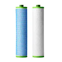
CARBON/MEDIA LOADING
1. Remove the In and Out valve assembly from the top of the tank and make sure the riser tube is secured to the vortech plate. The distributor is
permanently a ached to the vortech plate so centering is not necessary. The top of the distributor will be 5/8” above the top of the tank.
2. Cover the top opening of the distributor pipe before fi lling the tank with media.
3. Pour the coconut carbon provided with the unit into the top of the tank. Then pour the scale control media on top of the carbon.
4. Remove the material used to cover the top of the distributor pipe and clean the tank threads of any media. Rea ach the in and out valve
assembly.
Inlet
Valve
Outlet
Valve
Inlet
Valve
Outlet
Valve
Bypass
Valve
Boiler
Drain
20 Micron
Cartridge
Filter
6
REPLACEMENT PARTS
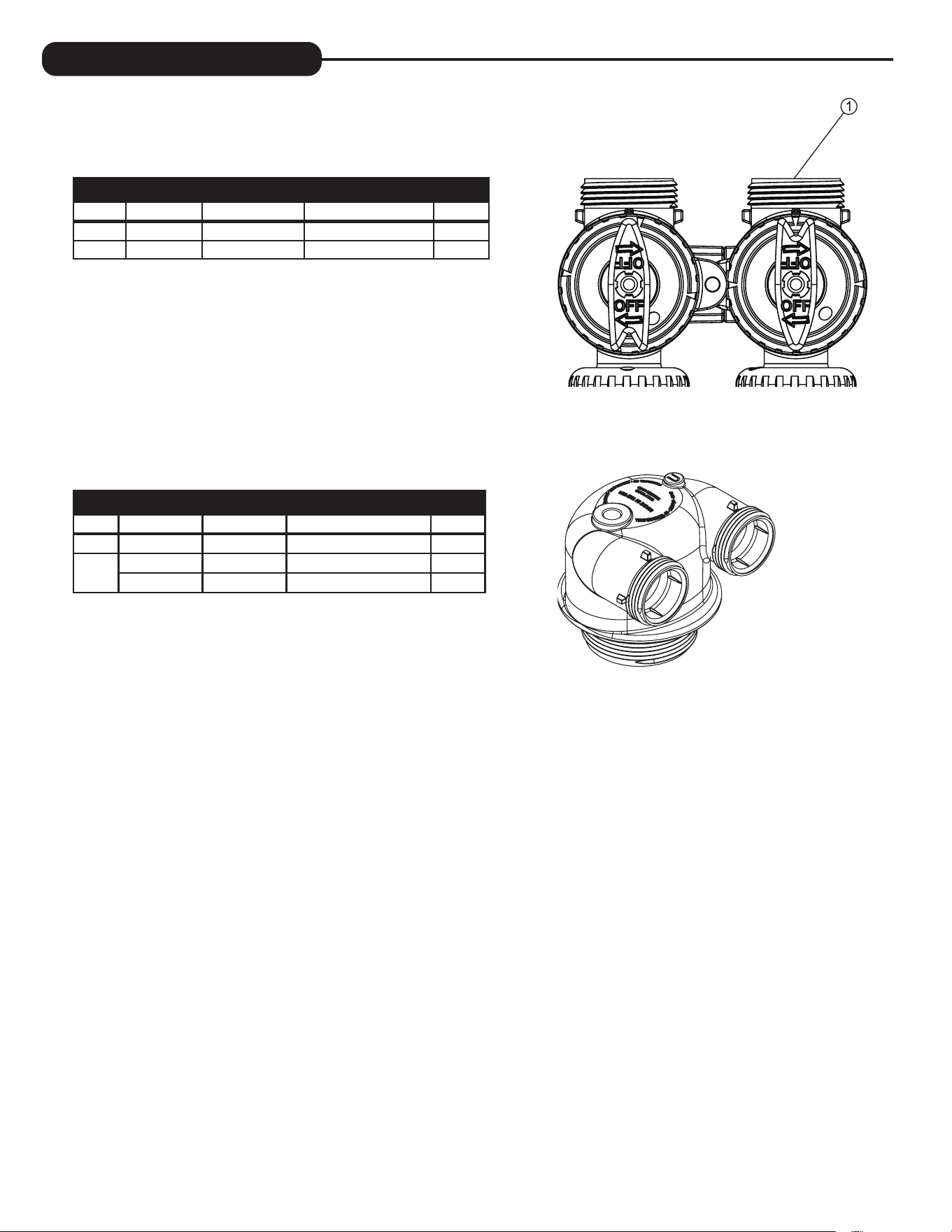
BYPASS VALVE
Item #. Legacy Part # Current Part # Description Qty.
1 CV3006 100249845 Bypass assembly 1
2 CV3147 100246284 Bypass handles 2
IN/OUT HEAD
Item # Legacy Part # Current Part # Description Qty.
CD1400 100245769 1191 In/Out Head 1
Not
Shown
CV3180 100246307 Base O-Ring 1
CV3105 100246272 Distributor Pilot O-Ring 215 1
4.91
124.7
4.43
112.4
4.14
105
6 7
Legacy Part # Current Part # Description Qty.
CV3007 100246197
1” PVC male NPT
elbow assembly
2
Legacy Part # Current Part # Description Qty.
CV3007-01 100246198
3/4” & 1” PVC solvent
elbow assembly
2
Legacy Part # Current Part # Description Qty.
CV3007-02 100246199
1” brass sweat
assembly
2
Legacy Part # Current Part # Description Qty.
CV3007-03 100249846
3/4” brass
sweat assembly
2
Legacy Part # Current Part # Description Qty.
CV3007-12 100249847
3/4” brass shark
bite assembly
2
Legacy Part # Current Part # Description Qty.
CV3007-13 100249848
1” brass shark
bite assembly
2
Legacy Part # Current Part # Description Qty.
CV3007-15 100246200
3/4” john guest
elbow assembly
2
Legacy Part # Current Part # Description Qty.
CV3007-17 100245045
1” john guest
assembly
2
Legacy Part # Current Part # Description Qty.
CV3007-09 100243922
1-1/4” & 1-1/2” brass
sweat assembly
2
Legacy Part # Current Part # Description Qty.
CV3007-07 100243375
1-1/4” & 1-1/2” PVC
solvent assembly
2
Legacy Part # Current Part # Description Qty.
CV3007-04 100244506
1” plastic male NPT
assembly
2
Legacy Part # Current Part # Description Qty.
CV3007-05 100243921
1-1/4” plastic male
assembly
2
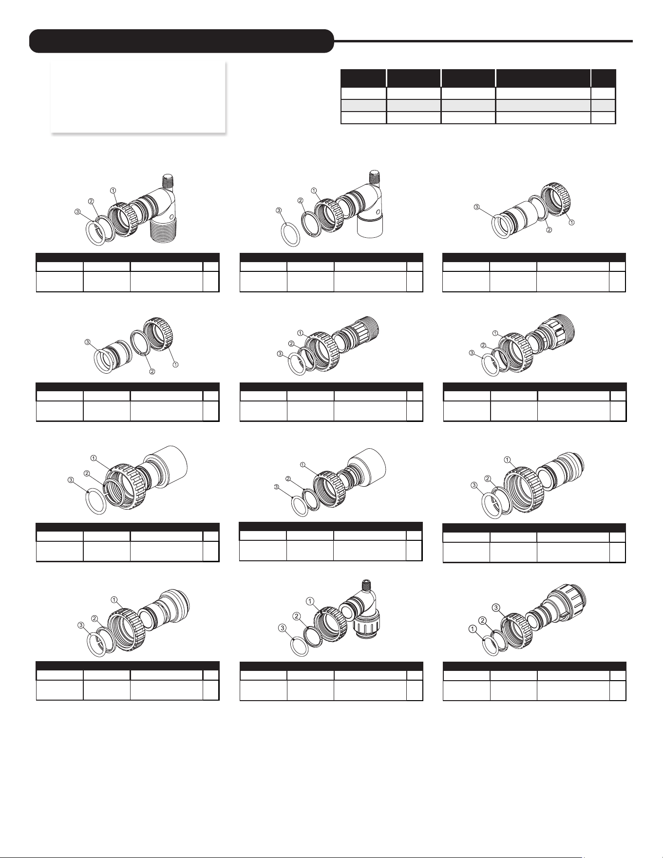
Item # Legacy Part # Current Part # Description Qty.
1 CV3151 100246287 Nut, 1” quick connect 2
2 CV3150 100246286 Split ring 2
3 CV3105 100246272 O-ring 215 2
NOTE: Not all available ttings are
displayed below. Contact
manufacturer for optional
ttings.
For All Assemblies
INSTALLATION FITTING ASSEMBLIES

8
This page intentionally left blank.

8 9
Water Filter Limited Warranty
Congratulations. You have purchased one of the nest water treatment systems available. In the unlikely
event of a problem due to defects in material and workmanship, we proudly warrant our water lters to the
original owner, when installed in accordance with A. O. Smith
®
speci cations. This warranty is effective from
the date of original installation for:
A period of TEN YEARS: Fiberglass mineral tanks 13” and smaller; except for damages
due to freezing, high pressure (120 PSI and above), extreme
temperature (100°F and above) or a vacuum on the system.
A period of FIVE YEARS: Valve Body and PC Board.
Fiberglass mineral tanks 14” and larger.
A period of ONE YEAR: All other lter components.
Any part found defective within the terms of this warranty will be repaired or replaced by the dealer. You pay
only freight from our factory and local dealer charges. To obtain local warranty service, contact original dealer
or an authorized service dealer. If no authorized dealer is located in your area, please ship defective part or
component freight prepaid to A. O. Smith, 1900 Prospect Ct., Appleton, Wisconsin 54914. A. O. Smith, at its
discretion, will repair or replace the part or component at its expense and return part freight collect.
The above provisions of the warranty are valid as long as the unit is connected in compliance with local
plumbing codes and in an equivalent manner and condition of the original installation and is owned by the
original owner.
This warranty does not cover damages due to accident, re, ood, freezing, or any other Act of God.
We are not responsible for damages due to change in water conditions, misapplication, misuse, neglect,
vacuum, oxidizing agents, alteration, or lack of maintenance. No responsibility is assumed for loss of use
of the unit, inconvenience, loss or damage to real or personal property or any incidental or consequential
damages. Furthermore, we assume no liability and extend no warranties, express or implied, for the use
of this product with a non-potable water source. To the extent permitted by law, A. O. Smith disclaims
all implied warranties, including without limitation warranties of merchantability and tness for
particular purpose; to the extent required by law, any such implied warranties are limited in duration
to the aforementioned period speci ed above.
Some states do not allow the exclusion of implied warranties or limitations on how long an implied warranty
lasts. Consequently, the above limitation may not apply to you.
This warranty gives you speci c legal rights, and you may also have other rights which vary from state
to state.

This page intentionally left blank.
11
QUICK REFERENCE GUIDE
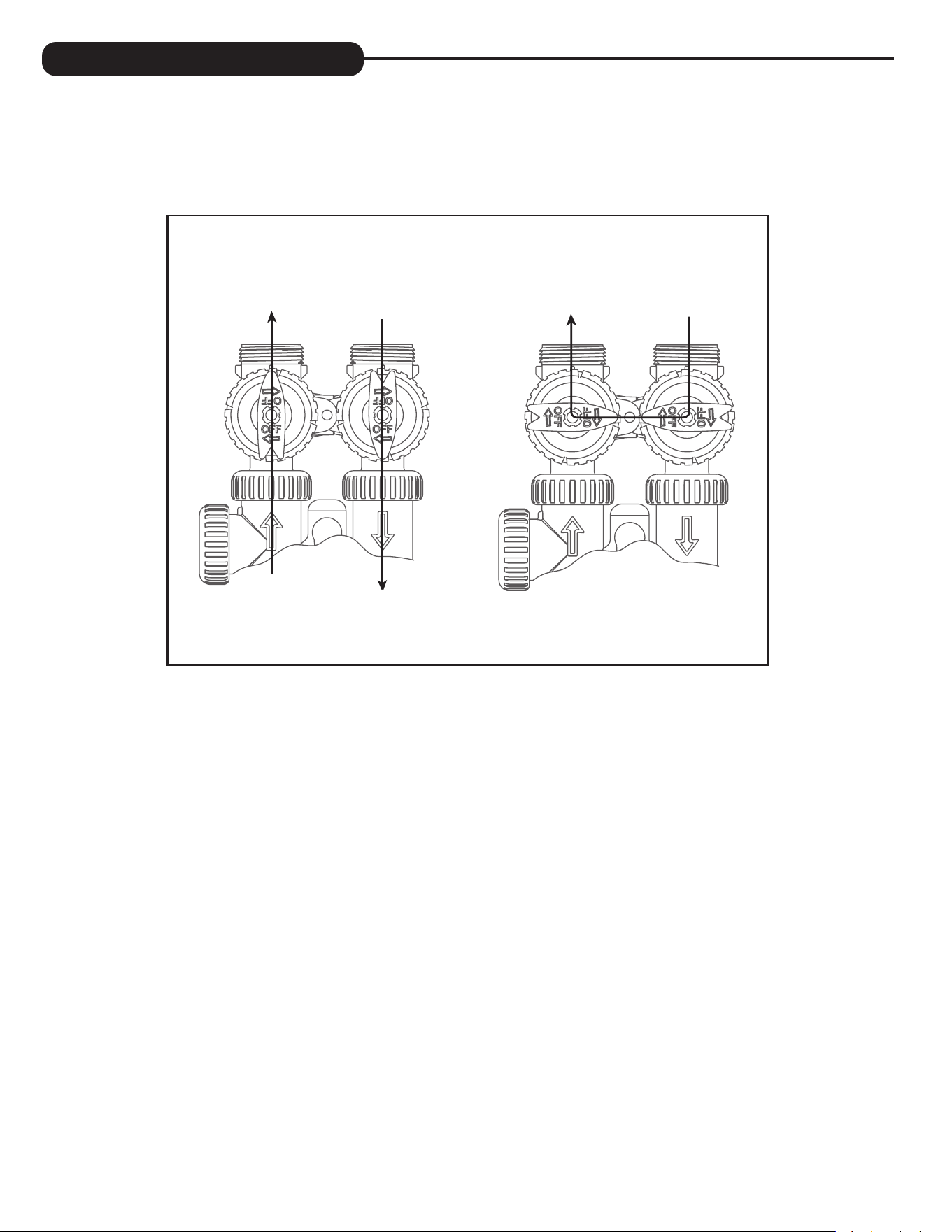
BYPASS VALVE OPERATION
To shut off water to the system, position arrow handles as shown in the bypass operation diagram below. If your valve doesn’t look like the
diagram below, contact your service technician for instructions on how to shut off water.
“TREATED”
WATER EXITS
SUPPLY
WATER ENTERS
SUPPLY
WATER EXITS
SUPPLY
WATER ENTERS
NORMAL OPERATION BYPASS OPERATION
Note: Bypass handles shown as shipped. Red handles can be popped off and turned to indicate proper
fl ow direc on of the FC-1000.

© 2024 A. O. Smith Corporation. All rights reserved. AOS-AOP DESCALE MAN - 100382600 - 2000835809 - RevA1024
1900 Prospect Court, Appleton, WI, 54914
aosmith.com/watertreatment