1
Serial Number
AK24053
Purchase Date
ITEM #6020797
MODEL #37000151
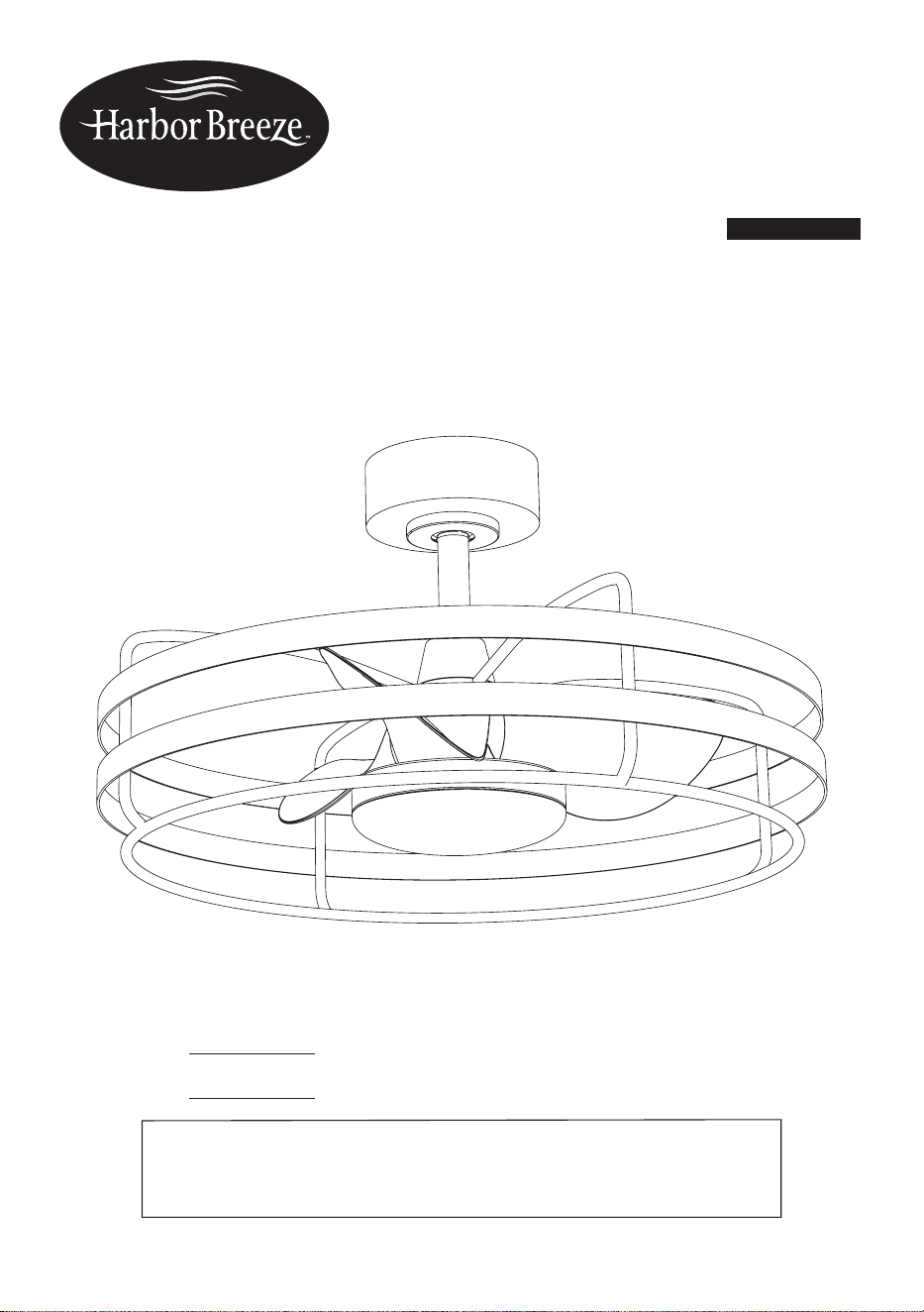
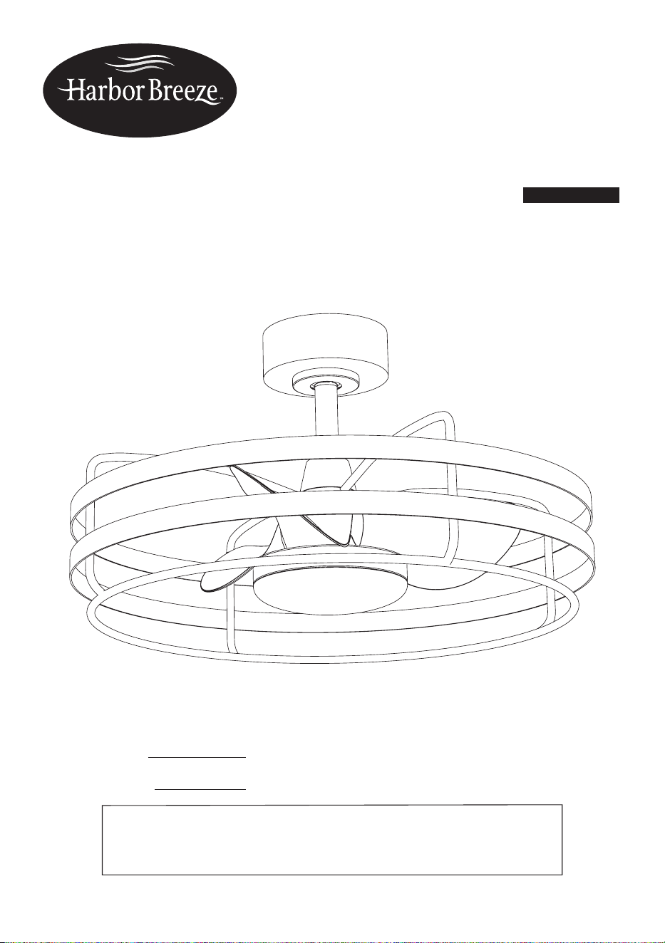
SPHERE
CEILING FAN
Español p. 21
ATTACH YOUR RECEIPT HERE
Thank you for purchasing this HARBOR BREEZE product.
Questions, problems or missing parts?
Before returning, contact us on:
888-251-1003, 8 a.m. - 8 p.m., EST, Monday - Sunday or [email protected].
HARBOR BREEZE and logo design are
trademarks or registered trademarks of LF,
LLC. All rights reserved.
2
TABLE OF CONTENTS
PRODUCT SPECIFICATIONS
Package Contents..................................................................................................................................
Hardware Contents.................................................................................................................................
Safety Information..................................................................................................................................
Preparation............................................................................................................................................
Pre-installation........................................................................................................................................
Installation Instructions...........................................................................................................................
Fan and remote control operation .........................................................................................................
Maintenance .........................................................................................................................................
Troubleshooting.....................................................................................................................................
Three Years Limited Warranty...............................................................................................................
Technical Service...................................................................................................................................
3
4
5
8
8
9
18
19
19
20
20
SPECIFICATIONS
Remote control
Dimmable
5 color select
Silent operation
DC motor
Energy efcient 30W
Reversible motor
SPECIFICATIONS
6 Speed
1250 CFM, 400 RPM
Integrated LED
1000 lumens, 80 CRI
30,000 hours
24” diameter (fully assembled)
Net weight of fan: 10.36lb /4.7kg
Model
Min. Thickness of edges
of blades (in./mm)
Blade length (in./cm) RPM
Speed at tip of blades
(ft/s, m/s)
37000151 0.126" (3.2mm) 8.66" (22cm) 400 33.69ft/s (10.27m/s)
3
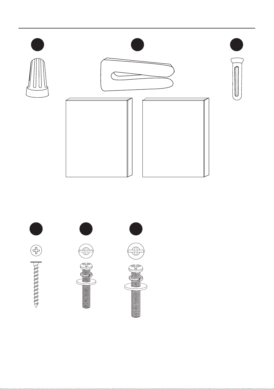
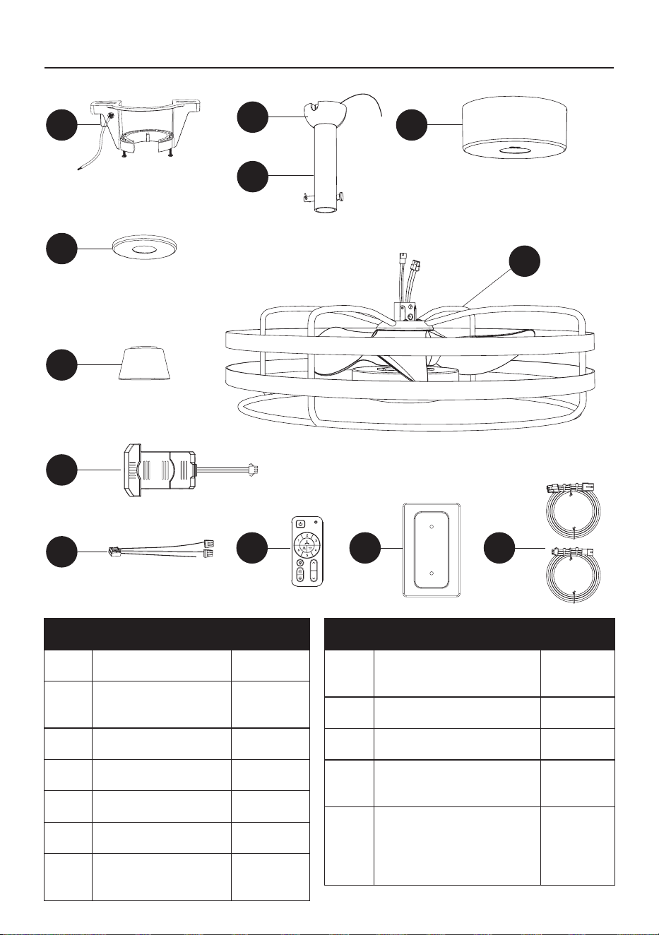
PACKAGE CONTENTS
A D
B
C
E
F
G
I J K
PART DESCRIPTION QUANTITY
A Mounting bracket 1
B
Hanger ball
(pre-assembled)
1
C Downrod 1
D Canopy 1
E Canopy ring 1
F Decorative cover 1
PART DESCRIPTION QUANTITY
G Fan motor housing 1
H Remote control receiver 1
H-1 Receiver wires 1
I Remote control 1
J
Remote control back plate
1
K
Extra extension wires for
longer downrod (downrod
sold separately)
2
H
H-1
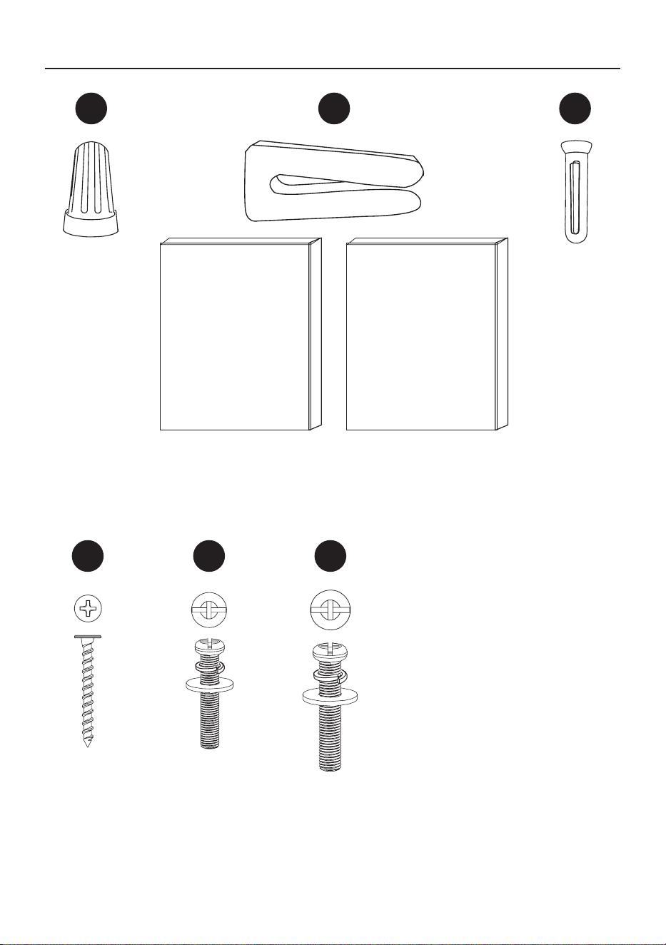
4
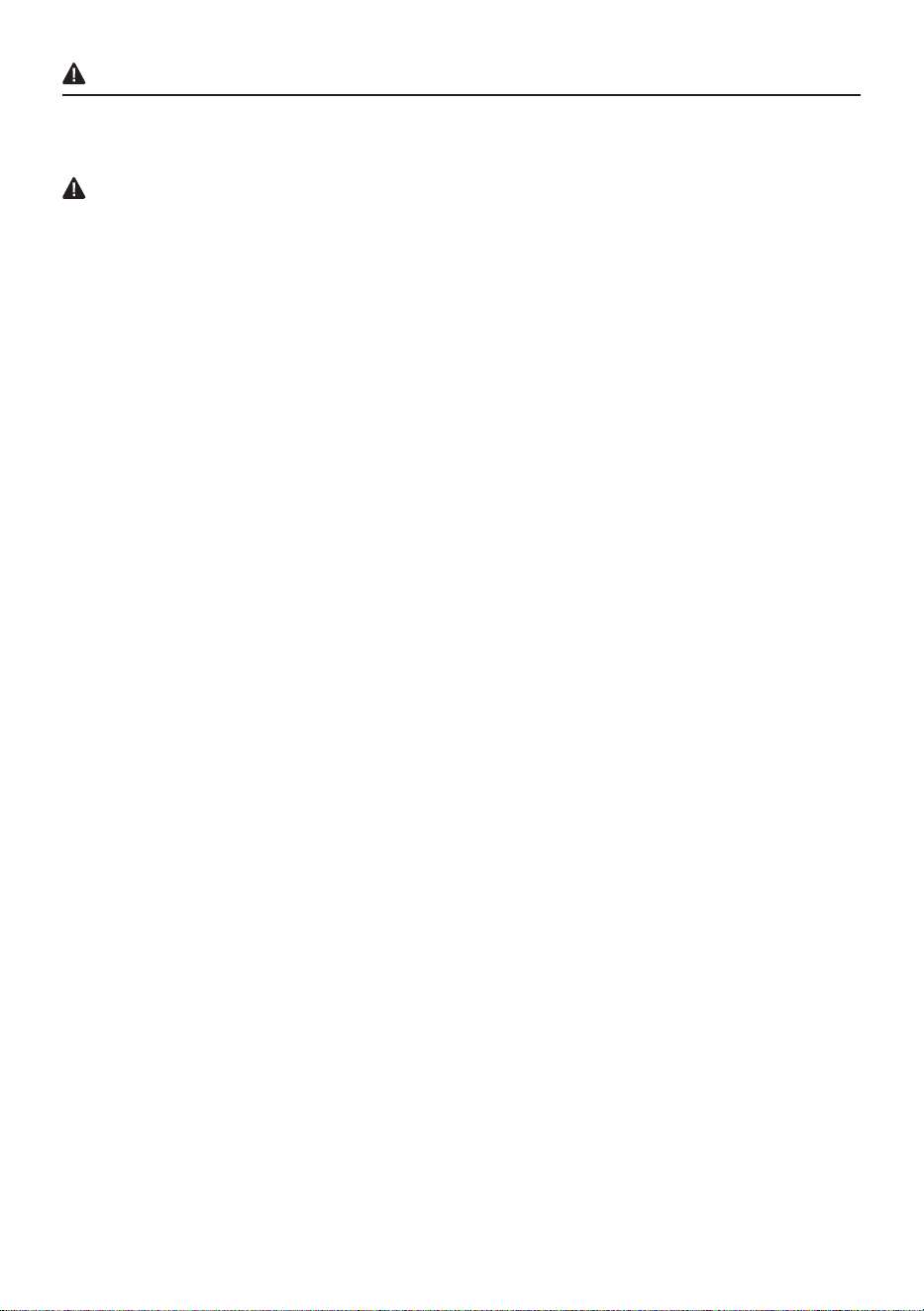
Balancing kit
Qty. 1
Extra Junction
Box screws and
washers #10-24 x
1” (2.54 cm)
Qty. 2
HARDWARE CONTENTS
Remote
control back
plate screw
anchors
Qty. 2
Wire
Nut
Qty. 2
Extra Junction
Box screws
and washers
#8-32 x 1”
(2.54 cm)
Qty. 2
AA BB
FF
CC
Remote
control back
plate screw
Qty. 2
DD EE
5
WARNING
Most electrical accidents are caused by carelessness or ignorance. If you combine a basic knowledge
of electricity, a healthy respect for it, and a dose of common sense, you can safely tackle many
household electrical repairs. Here are some basic guidelines for working with electricity:
•
Before working on a circuit, go to the main service panel and remove the fuse or trip the breaker that
controls that circuit. Tape a sign to the panel warning others to leave the circuit alone while you work.
• Before touching any wire, use a voltage tester to make sure it’s not live.
•
Whenever you check for voltage in a receptacle, check both outlets – each may be controlled by a
separate wiring circuit.
•
When replacing fuses, turn off the main power rst. Make sure your hands and feet are dry, and
place one hand behind your back to prevent electricity from making a complete circuit through your
chest.
• Touch a plug fuse only by its insulated rim. Remove cartridge fuses with a fuse puller.
• Use tools with insulated handles and ladders made of wood or berglass.
• Keep dry-chemical re extinguishers in the kitchen, basement, and workshop.
•
Never disable grounding devices. Make sure that all appliances requiring grounding are properly
grounded, and that the electrical system itself is properly grounded.
• Meet or exceed all electrical code requirements that cover the work you are doing.
•
Always work with enough light to see what you are doing; it’s easy to make mistakes when you’re
working in dim light.
If in doubt, consult a qualied electrician.
SAFETY INFORMATION
Please read and understand this entire manual before attempting to assemble, operate or install
the product.
6
SAFETY INFORMATION
WARNING
• Ensure the batteries are installed correctly according to polarity (+ and -).
• Remove and immediately recycle or dispose of used batteries according to local regulations and
keep away from children. Do not dispose of batteries in household trash or incinerate.
• Do not dispose of batteries in re. Batteries may explode or leak.
• Even used batteries may cause severe injury or death.
• Call a local poison control center for treatment information.
• CR2032 3V replaceable battery.
• Non-rechargeable batteries are not to be recharged.
• Do not force discharge, recharge, disassemble, heat above (60°C) or incinerate. Doing so may
result in injury due to venting, leakage or explosion resulting in chemical burns.
• Do not mix old and new batteries, different brands or types of batteries, such as alkaline,
carbon-zinc, or rechargeable batteries.
• Remove and immediately recycle or dispose of batteries from equipment not used for an extended
period of time according to local regulations.
• Always completely secure the battery compartment. If the battery compartment does not close
securely, stop using the product, remove the batteries, and keep them away from children
WARNING
INGESTION HAZARD:
This product contains a button cell or coin battery.
• INGESTION HAZARD: This product contains a button cell or
coin battery.
• DEATH or serious injury can occur if ingested.
• A swallowed button cell or coin battery can cause Internal
Chemical Burns in as little as 2 hours.
• KEEP new and used batteries OUT OF REACH of CHILDREN.
• Seek immediate medical attention if a battery is suspected to
be swallowed or inserted inside any part of the body
WARNING
WARNING
7
WARNING
•
To reduce the risk of re or electric shock, do not use this fan with any solid-state speed control
device.
• To reduce the risk of personal injury, do not bend the blade brackets when installing the brackets,
balancing the blades, or cleaning the fan. Do not insert foreign objects in between rotating fan blades.
• To reduce the risk of re, electric shock, or personal injury, mount to outlet box marked “acceptable
for fan support of 15.9/22.7/31.8 kg (35/50/70 lbs) or less” and use mounting screws provided with the
outlet box.
SAFETY INFORMATION
CAUTION
•
To r
educe the risk of electric shock, disconnect the electrical supply circuit to the fan before installing
light kit.
RF Exposure
The equipment complies with FCC radiation exposure limits set forth for an uncontrolled environment.
This device should be installed and operated with a minimum distance 20cm between the radiator and
your body.
This device complies with part 15 of the FCC Rules. Operation is subject to the following two
conditions: (1) This device may not cause harmful interference, and (2) this device must accept any
interference received, including interference that may cause undesired operation.
• Changes or modications not expressly approved by the party responsible for compliance could void
the user’s authority to operate the equipment.
NOTE: This equipment has been tested and found to comply with the limits for a Class B digital
device, pursuant to Part 15 of the FCC Rules. These limits are designed to provide reasonable
protection against harmful interference in a residential installation. This equipment generates uses and
can radiate radio frequency energy and, if not installed and used in accordance with the instructions,
may cause harmful interference to radio communications. However, there is no guarantee that
interference will not occur in a particular installation. If this equipment does cause harmful interference
to radio or television reception, which can be determined by turning the equipment off and on, the user
is encouraged to try to correct the interference by one or more of the following measures:
• Reorient or relocate the receiving antenna.
• Increase the separation between the equipment and receiver.
• Connect the equipment into an outlet on a circuit different from that to which the receiver is connected.
• Consult the dealer or an experienced radio/TV technician for help.
FCC Responsible Party:
Globe Electric, 2264 East 6th Street, San Bernardino, CA 92410
www.globe-electric.com
CAN ICES (B) / NMB (B)
This device contains licence-exempt transmitter(s)/receiver(s) that comply with Innovation, Science
and Economic Development (ISED) Canada’s licence-exempt RSS(s). Operation is subject to the
following two conditions: (1) this device may not cause interference, and (2) this device must accept
any interference, including interference that may cause undesired operation of the device.
The device has been evaluated to meet general RF exposure requirement.
The distance between user and products should be no less than 20 cm.
WARNING
8
Fan must be able to be secured to a fan-rated outlet box. If none exists, contact a qualied electrician
for installation.
PRE-INSTALLATION
Before beginning assembly of product, make sure all parts are present. Compare parts with package
contents list and hardware contents list. If any part is missing or damaged, do not attempt to
assemble, install, or operate the product.
Estimated Assembly Time: 15-20 minutes
Tools Required for Assembly (not included): Phillips head screwdrivers, adjustable wrench, wire cutter,
electrical tape and step ladder.
NOTE:
•
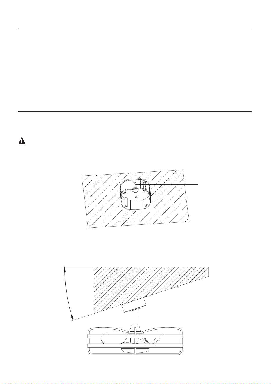
Fan can be mounted on a sloped ceiling up to a maximum angle of 15 degrees.
PREPARATION
11
55
°°
Outlet Box
WARNING
• To reduce the risk of re, electric shock, or personal injury, mount to outlet box marked “acceptable
for fan support of 15.9/22.7/31.8 kg (35/50/70 lbs) or less” and use mounting screws provided with
the outlet box.
9
INSTALLATION INSTRUCTIONS
2
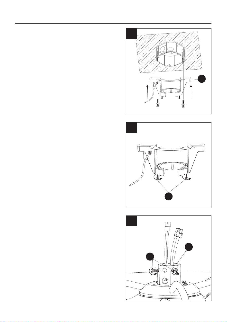
2. Loosen (do not remove) the 2 mounting bracket
screws (SS).
SS
1
1. Secure the mounting bracket (A) to the ceiling
outlet box with the screws and washers provided
with your outlet box.
NOTE: Extra junction box screws #8-32 x 1”
(2.54 cm) and washers (EE) and #10-24 x 1”
(2.54 cm) and washers (FF) found in hardware
bag included if needed.
1
A
1
3. Loosen the 2 set screws (QQ) on the fan motor
housing (G).
3
G
QQ
10
1
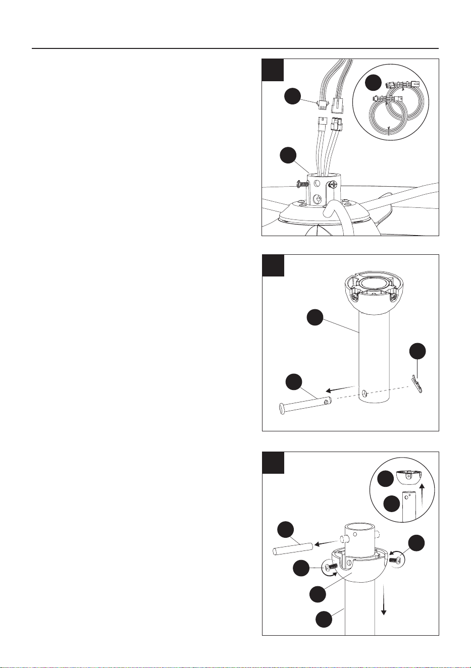
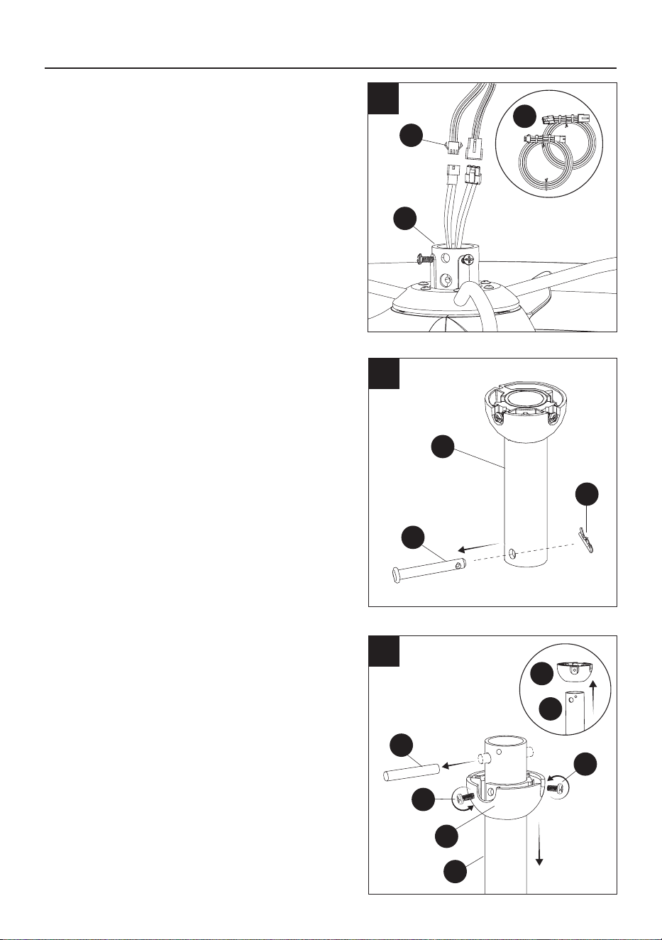
4. If you need to install a longer downrod, attach
the included extension wires (K) to the fan motor
housing (G).
INSTALLATION INSTRUCTIONS
4
C
OO
PP
G
B
B
C
C
5
6
5. Remove the locking pin (PP) and the hanging
pin (OO) from the downrod (C).
MM
VV
NN
6. Remove the hanger ball (B) from the
downrod (C) by removing the hanger ball
screws (NN) and (VV), and removing the
cross pin (MM); then slide the hanger ball (B)
off the downrod (C).
K
K
11
C
OO
PP
PP
OO
G
QQ
INSTALLATION INSTRUCTIONS
WARNING
• Failure to properly install the motor housing
locking pin could result in the fan becoming
loose and possibly falling.
1
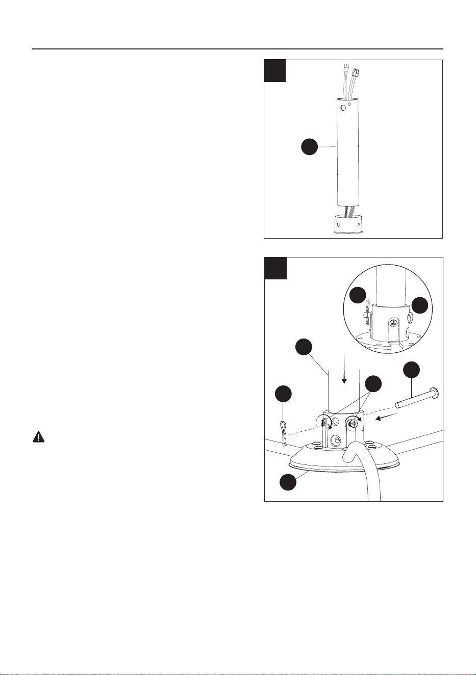
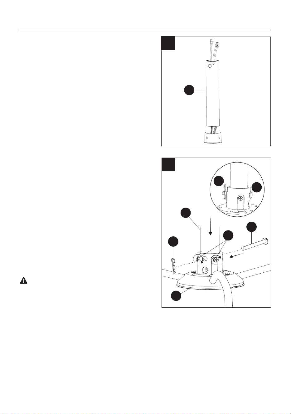
7. Carefully feed the motor housing wires up
through the downrod (C).
7
8
8. Insert the downrod (C) into the motor housing
(G). Align the holes and reinstall the hanging
pin (OO) and secure with the locking pin (PP).
Tighten the set screws (QQ).
NOTE: If you feel resistance while pushing in
the hanging pin, push cable wires aside.
CAUTION
•
T
o avoid damage and to ensure a wobble-free
operation, the downrod and motor housing set
screws must be fully tightened until you feel
resistance.
C
12
C
10
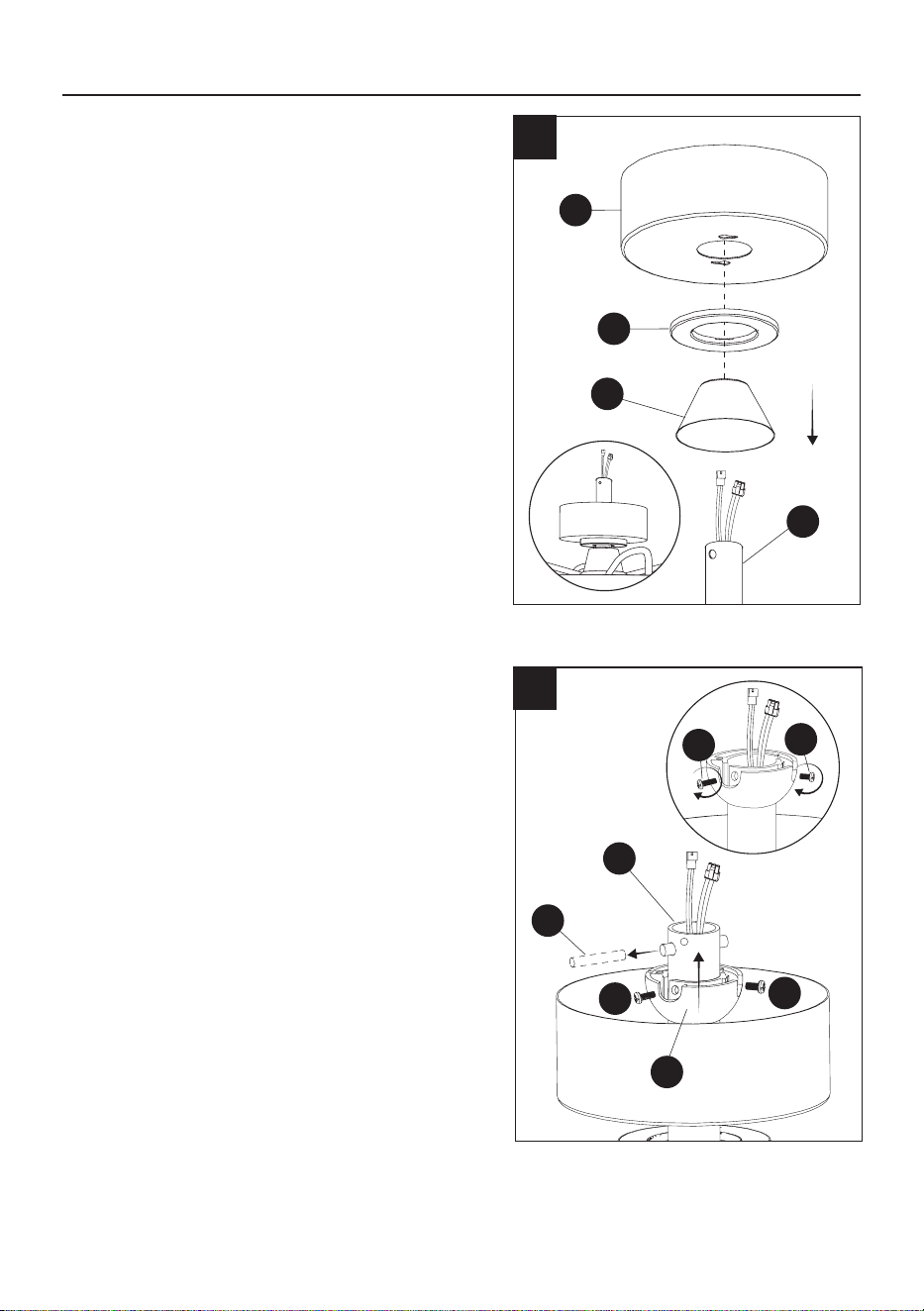
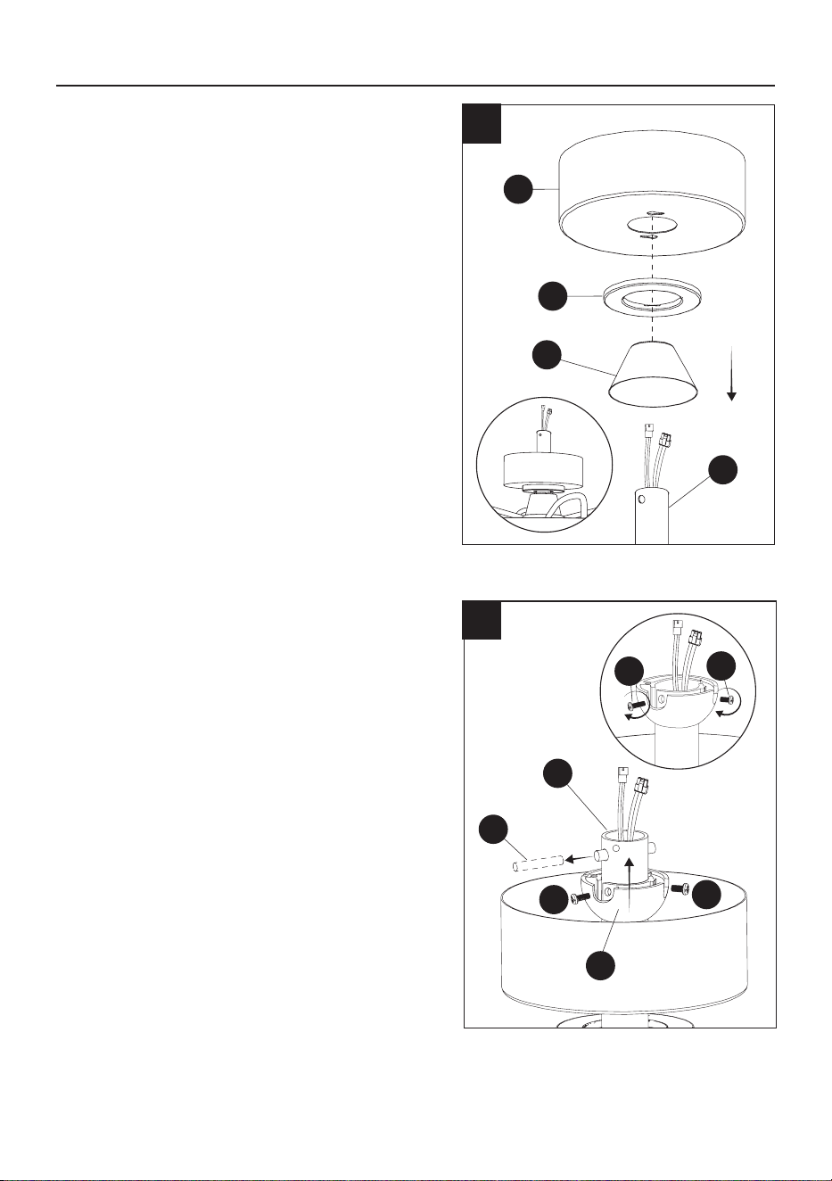
10. To reinstall the hanger ball (B), slide it onto the
downrod (C) and reinsert the cross pin (MM)
into the large hole. Slide the hanger ball (B)
up so that the cross pin (MM) is secured in the
groove, ensuring the screw holes are aligned
correctly, larger screw (VV) should align with
the hole in the downrod (C) and screw in both
screws (NN) and (VV).
NOTE: Ensure wires are not twisted.
CAUTION
•
A
loose screw could result in wobbling of the fan.
INSTALLATION INSTRUCTIONS
1
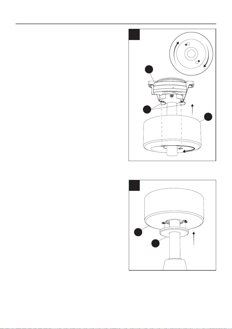
9. Slide the decorative cover (F) onto the downrod
(C). Then slide the canopy ring (E) and the
canopy (D), both facing upwards, onto the
downrod (C).
9
D
F
E
C
B
MM
VV
NN
VV
NN
13
B
A
A
B
TT
TT
UU
UU
12
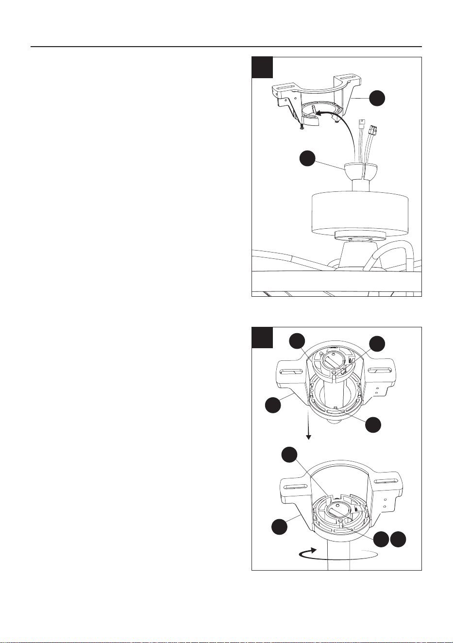
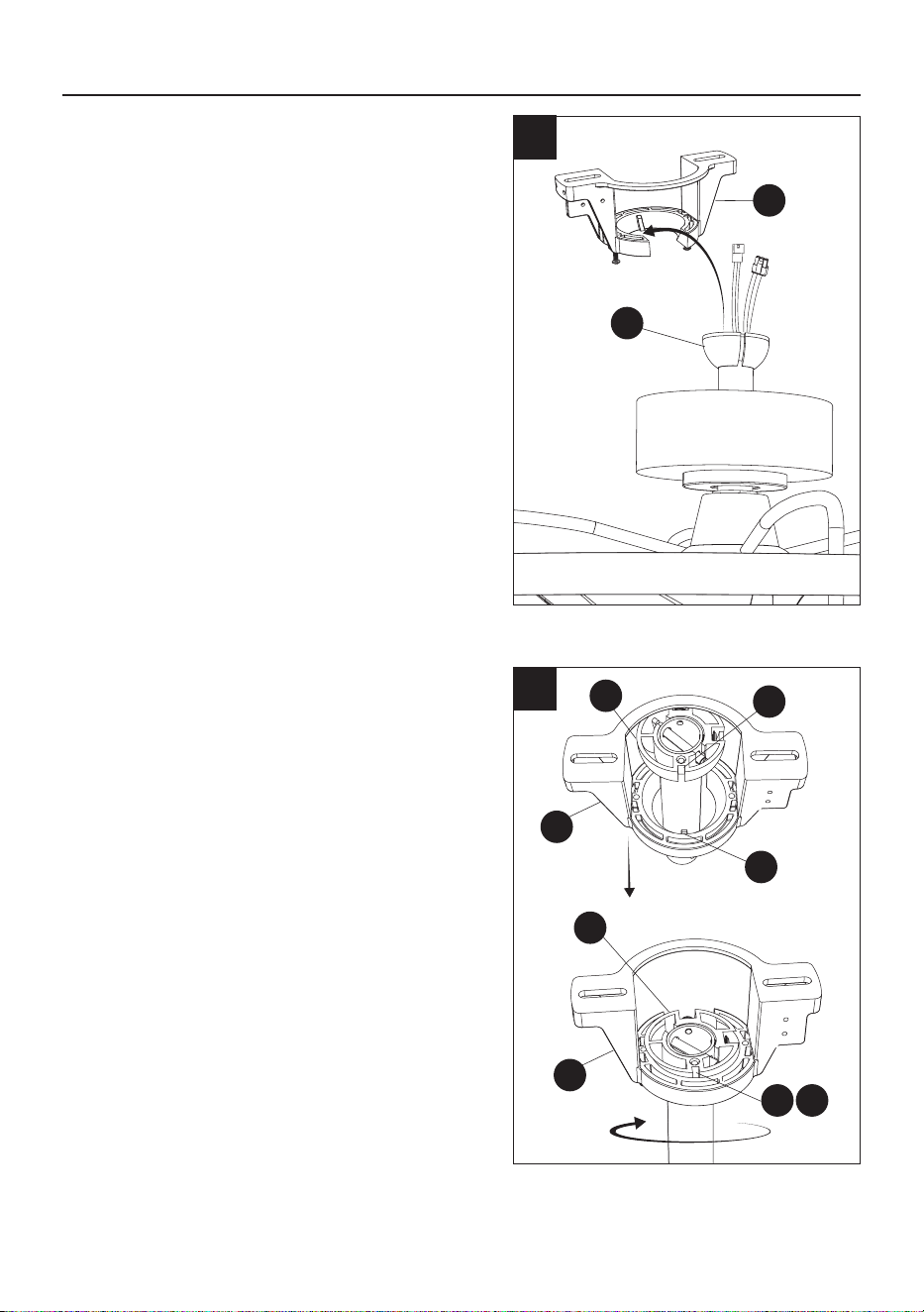
12. Rotate the assembled fan clockwise until the
groove (TT) on the hanger ball (B) drops into
the slot (UU) on the bracket (A) and sits rmly.
The hanger ball (B) should no longer be able to
rotate if this is done correctly.
CAUTION
•
Failure to align groove on ball with ridge could
result in wobbling.
INSTALLATION INSTRUCTIONS
1
11. Lift the assembled fan to the ceiling and place
the hanger ball (B) into the mounting bracket
(A) opening.
CAUTION
•
To prevent damage to the fan, always lift up the
fan by the downrod or motor housing.
11
A
B
14
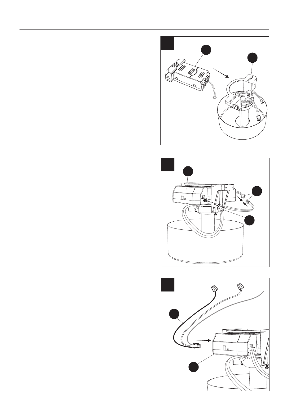
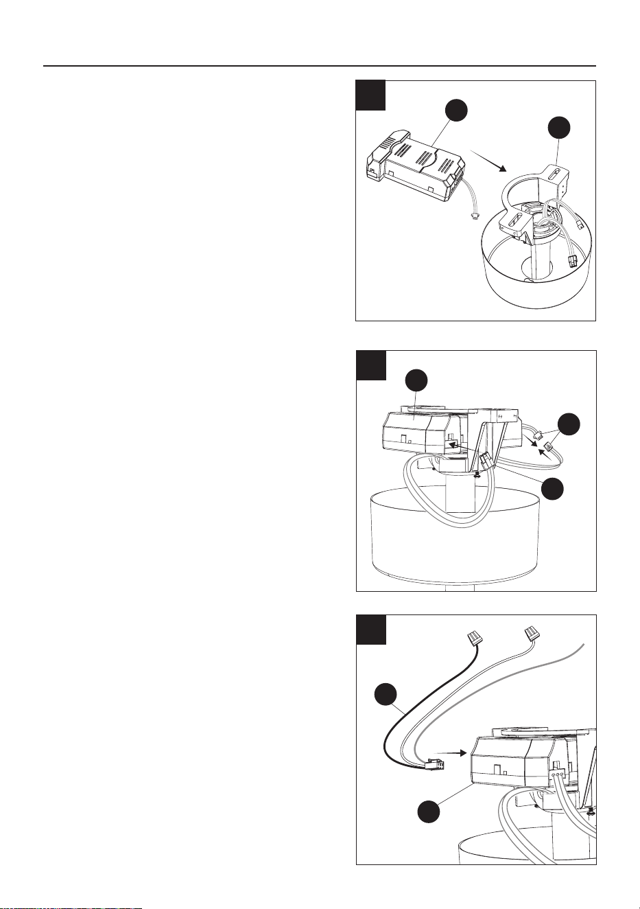
13. Insert the receiver (H) as shown, into the
mounting bracket (A) .
INSTALLATION INSTRUCTIONS
XX
H
H
14
15
14. Connect the motor housing wires (WW) to
the receiver (H) as shown and connect the
motor housing wires (XX) to the wires from the
receiver as shown.
H-1
15. Connect the receiver wires (H-1) to the
receiver (H) as shown.
WW
1
13
H
A
15
WARNING
• All wiring must be in accordance with the
National Electrical Code, ANSI/NFPA 70. If
wires at the installation site are any other color
than what is listed here, have this fan installed
by a qualied electrician.
• The ceiling fan must be grounded. If there
is no ground wire present on the installation
site (example, from the ceiling), STOP the
installation immediately and consult a qualied
electrician.
AA
16
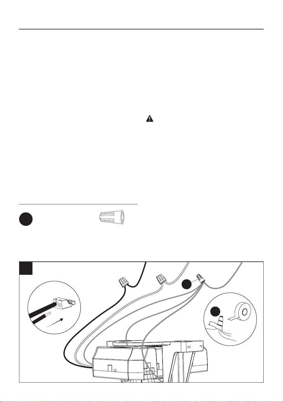
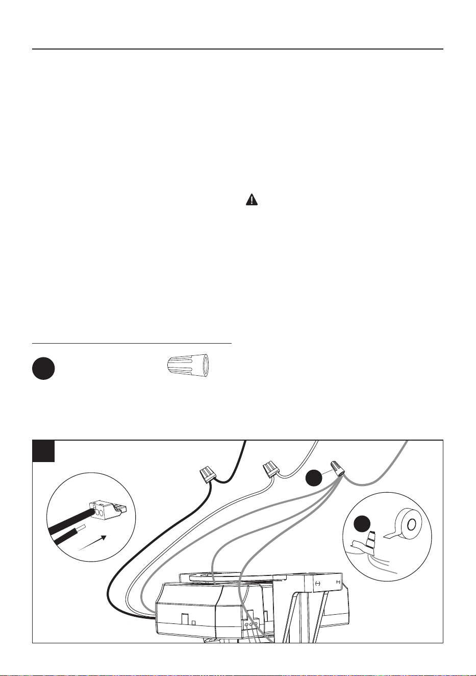
16. Connect the ceiling wires to the receiver wires as follows:
Insert the hot (black) wire from the ceiling into one of the free holes of the black wire quick connect
from the receiver and push the wire in all the way. Gently tug on wire to ensure it is secure in
connector.
Insert the neutral (white) from the ceiling into one of the free holes of the white wire quick connect
from the receiver and push the wire in all the way. Gently tug on wire to ensure it is secure in
connector.
Connect all ceiling fan ground wires to ceiling ground wire, as shown below, using the wire nut
(AA) found in hardware bag and wrap it with electrical tape. If your ceiling does not have a ground
wire, consult a qualied electrician.
Hardware Used
Wire Connectors x 1
AA
INSTALLATION INSTRUCTIONS
CAUTION
•
T
o reduce the risk of electric shock, disconnect
the electrical supply circuit to the fan before
wiring. if you do not feel your electrical wiring
knowledge or experience is sufcient, contact a
qualied electrician.
•
Do not install in a wet location.
NOTE: After connecting the wires, spread
them apart so that the ground / white wires
are on one side and the black wires are on
the other side.
NOTE: Optionally, if you’re having difculty
attaching the canopy due to the wires,
connect the receiver wires (H-1) to the
ceiling wires before placing receiver (H) into
the mounting bracket (A), and tuck the wire
connections into the outlet box.
Black White GroundCeiling Wires:
AA
16
D
D
E
18
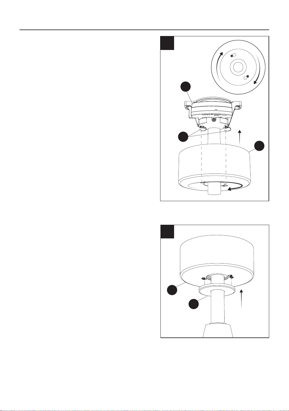
18. Slide the magnetic canopy ring (E) up to attach
to the canopy (D).
INSTALLATION INSTRUCTIONS
1
17. Attach the canopy (D) to the mounting bracket
(A) by aligning the mounting bracket screws
(SS) with the canopy keyholes and twist, then
tighten the mounting bracket screws (SS).
17
A
SS
17
Remote control back
plate screw anchors
Remote control back
plate screw
x 2
CC
INSTALLATION INSTRUCTIONS
19
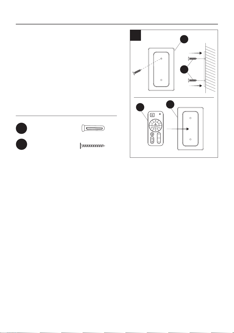
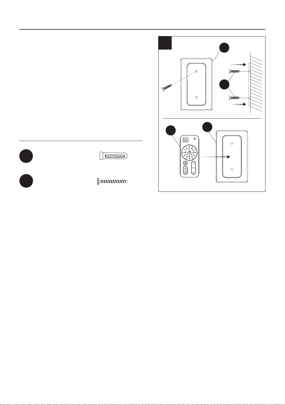
19. Secure the magnetic remote control back plate
(J) to preferred location to the wall with the
screw anchors (CC) and screws (DD) found in
accesories remote control bag.
Once the magnetic remote control back plate
(J) is securely mounted, place the remote
control (I) in the back plate (J) to hold in place.
Hardware Used
x 2
DD
I
J
DD
J
18
FAN AND REMOTE CONTROL OPERATION
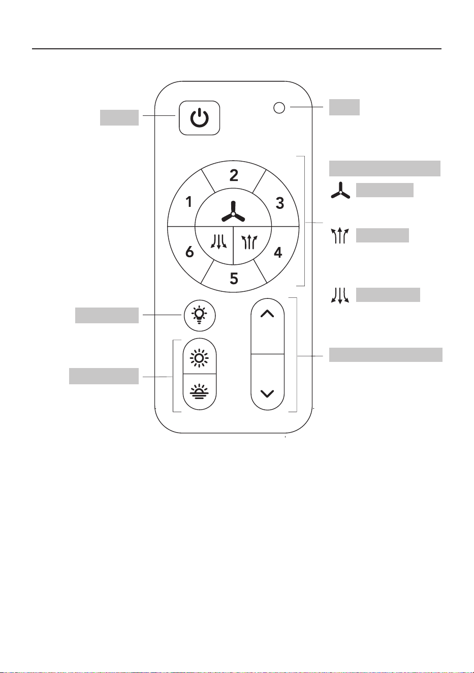
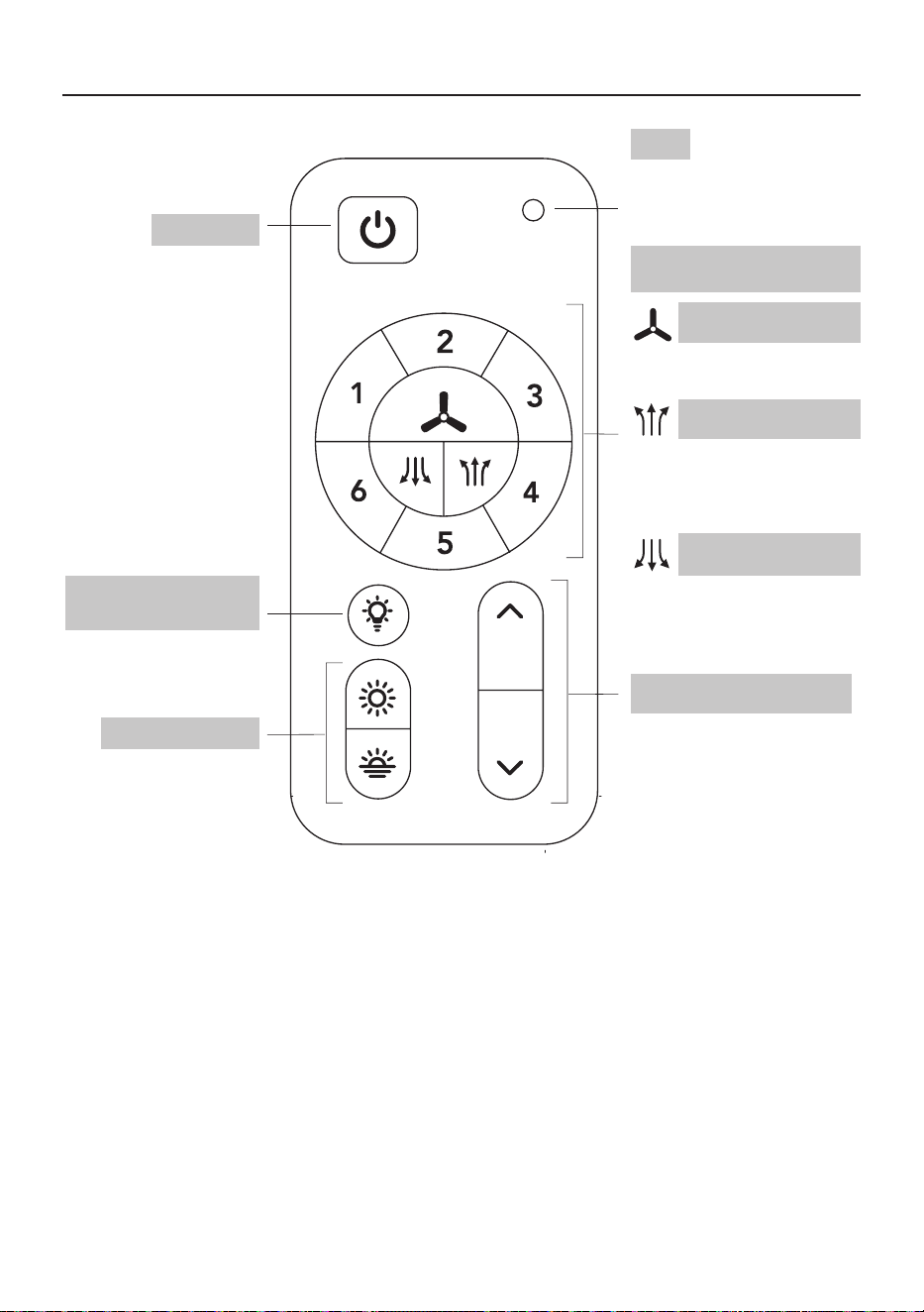
NOTE: Remote uses 1 CR2032 button cell battery (included).Remove the plastic tab on battery door
before using remote. When replacing the battery, ensure the battery door is closed all the way (you
will hear a click).
NOTE: The device has been evaluated to meet RF exposure requirements. The device can be used
in portable exposure conditions without restriction.
This equipment complies with FCC radiation exposure limits set forth for an uncontrolled environment.
Press button to switch fan’s
rotation upward to circulate
rising warm air
Press button to switch fan’s
rotation downward for a
cool downdraft
Light On/Off
Tunable white
Power
LED
#1-6: 6 fan speed levels
light dimmer up and down
Press button to turn fan
and light on or off
NOTE: Fan and light
will turn on to last state
Press button to turn
light on or off
Push buttons up or
down to cycle through
5 ambient White colors:
Cool Daylight, Daylight,
Cool White, Warm White
or Soft White
Blue LED indicator light will
illuminate when any button
is pressed
Press button to turn fan on
or off
Push buttons up or down
to increase or decrease
brightness
Fan On/Off
Fan air up
Fan air down
Remote control SKU#:
GE37106TX
19
TROUBLESHOOTING
CARE AND MAINTENANCE
• The fan’s natural movements may cause some connections to come loose. A clicking or rattling noise
is a certain sign of loosening screws. Check the support connections, brackets and blade attachment
twice a year, and tighten all screws as necessary.
• Make sure to disconnect the fan from the power supply before servicing or cleaning.
• Clean your fan periodically. Use only a damp cloth, never use solvents, and dust with a soft cloth or
brush.
• You will never need to oil your fan; its permanently sealed bearing will prevent noise.
• Do not operate when product is damaged. Discard fan or return to an authorized service facility for
inspection and/or repair.
• Total light xture wattage is 17 watts; do not attempt to replace LED.
PROBLEM SOLUTION
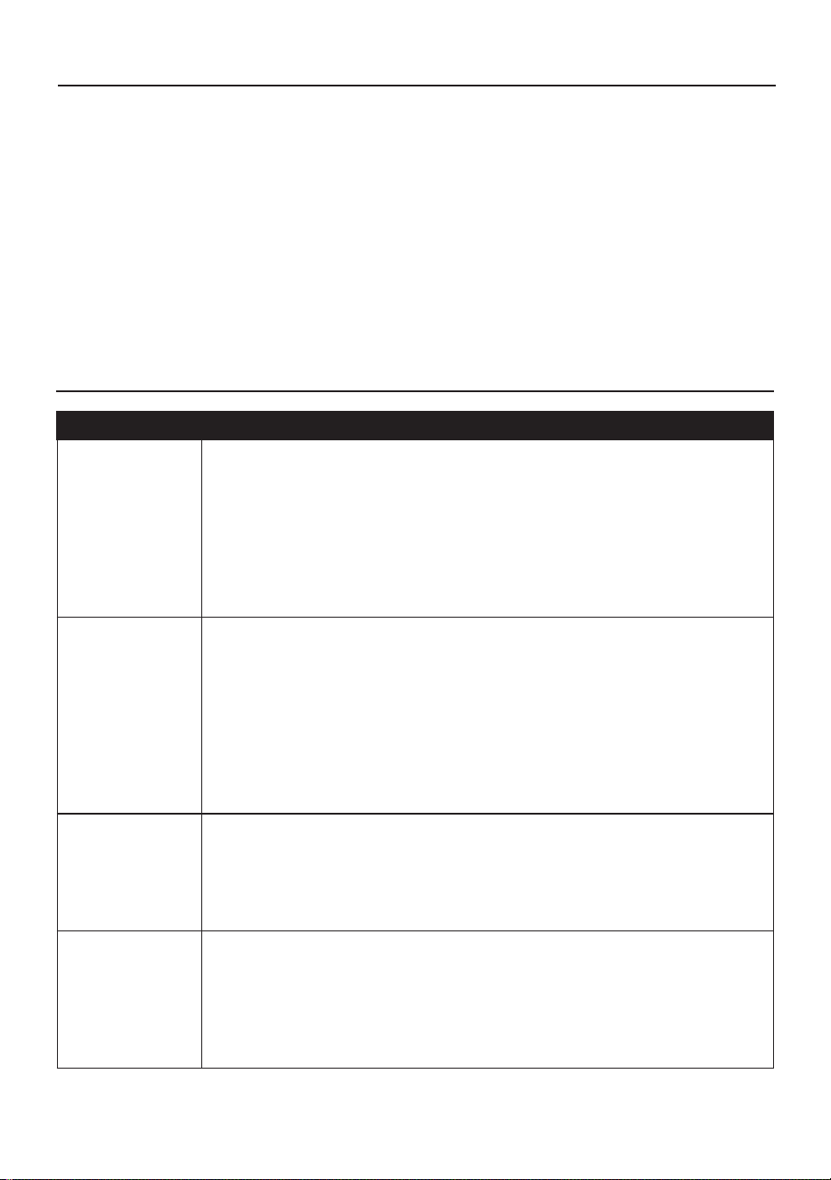
Fan/Light does
not start
1. Ensure wall switch is turned on.
2. Check all fuses/circuit breakers.
3. Turn off electrical power and ensure the wiring is correct and connectors
secured, as shown in steps 14, 15 and 16 of assembly.
4. Conrm that the remote is working; LED indicator light should illuminate
when any button is pressed.
5. If fan/light still will not start, contact a qualied electrician. Do not attempt to
troubleshoot internal electrical connections yourself
Fan is noisy 1. Allow a 24-hour “break in” period. Any level of noise louder than ambient
levels should disappear during that time.
2. Check the electrical outlet box and ensure it is securely fastened.
3. Check all screws/wire connections on the fan to ensure they are securely
fastened.
4. Use of an unapproved light dimmer or wall control can cause the fan to act
irregularly and produce excess noise. Check to ensure that if installed, the
wall control is approved for ceiling fan use; however, it is not suggested to
use a dimmer switch with the fan.
The fan moves
backwards and
forwards when
turned on
1. This is a normal start-up procedure for DC motor fans. The partial
movement during start-up is the result of the DC motor aligning the internal
magnetic poles for proper motor operation. This design saves electricity
and allows the fan to operate much more quietly than standard AC motor
fans.
Fan does not
move much air
1. Check the direction of the fan blades when running. If needed, change
the direction of the fan blades to ensure the ceiling fan is moving air in the
desired direction.
2. Ensure no household items are obstructing the airow of the ceiling fan.
3. Check to ensure the ceiling fan is appropriate for the size of the room in
which it is installed.
20
3-YEAR LIMITED WARRANTY
TECHNICAL SERVICE
What is covered
This product is guaranteed to be free of factory defective parts and workmanship for a period of
3 years from date of purchase. Purchase receipt is required for all warranty claims.
What is not covered
This guarantee does not include repair service, adjustment and calibration due to misuse, abuse or
negligence. Unauthorized service or modication of the product or of any furnished component will void this
warranty in its entirety. This warranty does not include reimbursement for inconvenience, installation, setup
time, loss of use, unauthorized service, or return shipping charges. This warranty is not extended to other
equipment and components that a customer uses in conjunction with this product.
If have any questions or problems, please call our customer service department at 888-251-1003,
8 a.m. - 8 p.m., EST, Monday - Sunday. You may also contact us at [email protected].
No service parts available for this product.
Please keep your dated sales receipt, it is required for all warranty requests.
Printed in China
TROUBLESHOOTING (CONTINUED)
PROBLEM SOLUTION
Fan shakes or
wobbles
1. A small amount of wobble is typical and acceptable and is not indicative
of a defect. Run fan for at least 10 minutes before verifying level of
wobble.
2. Ensure the electrical outlet box and hanging bracket are securely
fastened, as shown in step 1 of assembly.
3. Ensure the groove in the hanger ball is properly sitting in the bracket
slot; if not, turn hanger ball clockwise until ball drops into the slot, as
shown in step 11 of assembly.
4. Install the included balancing kit (BB). If undesired movement persists,
simply change the location of the balancing kit (BB) until the excess
movement ceases.
Remote control is
not working
1. Ensure plastic tab is removed from the battery compartment.
2. Ensure batteries are installed correctly in remote.
3. Ensure the remote/receiver are paired. If the batteries are new and
the LED indicator light is working, but the fan and/or light are still not
working, the remote may have become un-paired. To pair the remote
and fan, press the main on/off button on the remote 3 times within one
minute.
4. Ensure the wires from the receiver are correctly connected to the
house wiring and ceiling fan wires, as shown in steps 13, 14 and 15 of
assembly.
21
Número de serie
AK24053
Fecha de compra
ARTÍCULO #6020797
MODELO #37000151
VENTILADOR
DE TECHO
SPHERE
English p. 1
ADJUNTE SU RECIBO AQUÍ
Gracias por comprar este producto HARBOR BREEZE.
¿Tiene preguntas, problemas o piezas faltantes?
Antes de volver a la tienda, póngase en contacto al: 888-251-1003, de lunes a
domingo, de 8 a.m. a 8 p.m., hora estándar del Este, o en [email protected].
HARBOR BREEZE y el diseño del logotipo
son marcas comerciales o marcas registradas
de LF, LLC. Todos los derechos reservados.
22
ÍNDICE
ESPECIFICACIONES DEL PRODUCTO
Contenido del paquete..........................................................................................................................
Aditamentos...........................................................................................................................................
Información de seguridad......................................................................................................................
Preparación...........................................................................................................................................
Antes de la instalación...........................................................................................................................
Instrucciones de instalación..................................................................................................................
Funcionamiento del control remoto y el ventilador................................................................................
Cuidado y mantenimiento.......................................................................................................................
Solución de problemas..........................................................................................................................
Garantía limitada de tres años..............................................................................................................
Servicio técnico.....................................................................................................................................
23
24
25
28
28
29
38
39
39
40
40
ESPECIFICACIONES
Control remoto
Regulable
5 selecciones de color
Funcionamiento silencioso
Motor de DC
Eciencia energética 30W
Motor reversible
ESPECIFICACIONES
6 velocidades
35.39 M3/MIN, 400 RPM
LED integrado
1000 lúmenes, 80 IPC
30.000 horas
60.96 cm de diámetro (completamente ensamblado)
Peso neto del ventilador: 4.69 kg/10.36 lb
Modelo
Grosor mínimo de los
bordes de las aspas
(pulg./mm)
Largo de las aspas
(pulg./cm)
RPM
Velocidad en la punta
de las aspas (pies/s,
m/s)
37000151 0.126" (3.2mm) 8.66" (22cm) 400 33.69pies/s (10.27m/s)
23
CONTENIDO DEL PAQUETE
A D
B
C
E
F
I J K
PIEZA
DESCRIPCIÓN CANTIDAD
A Soporte de montaje 1
B
Bola para colgar
(preensamblada)
1
C Varilla 1
D Base 1
E Anillo de la base 1
F Cubierta decorativa 1
G
Carcasa del motor del
ventilador
1
PIEZA
DESCRIPCIÓN CANTIDAD
H Recibidor del control
remoto
1
H-1 Cables del receptor 1
I Control remoto 1
J
Placa posterior del control
remoto
1
K
Cables de extensión adicio-
nales para una varilla más
larga (la varilla se vende por
separado)
2
H-1
G
H
24
Kit de equilibrio
Cant. 1
Tornillos y arandelas
adicionales para la
caja de conexiones
#10-24 x 1”
(2.54 cm)
Cant. 2
ADITAMENTOS
Anclas de
expansión
para tornillo
de la placa
posterior
de control
remoto
Cant. 2
Empalme
plástico
Cant. 2
Tornillos y arandelas
adicionales para la
caja de conexiones
#8-32 x 1”
(2.54 cm)
Cant. 2
AA BB
FF
CC
Tornillo de
la placa
posterior
de control
remoto
Cant. 2
DD EE
25
ADVERTENCIA
La mayoría de los accidentes eléctricos son causados por descuidos o ignorancia. Si combina un
conocimiento básico con un poco de respeto por la electricidad y una dosis de sentido común, se
pueden abordar con seguridad muchas reparaciones eléctricas domésticas. A continuación encontrará
algunas pautas básicas para trabajar con electricidad:
•
Antes de trabajar en un circuito, vaya a
l panel de servicio principal y retire el fusible o desconecte el
interruptor que controla ese circuito. Pegue un letrero en el panel para advertir a otras personas que
no toquen el circuito mientras usted traba
ja.
•
A
ntes de tocar cualquier cable, use un medidor de voltaje para asegurarse de que no tenga
corriente.
•
Cuando verique el voltaje en un tomacorriente, revise las dos salidas, ya que cada una podría estar
controlada por un circuito de cableado separado.
•
Al reemplazar los fusibles, primero desconecte el suministro de electricidad. Asegúrese de que sus
manos y pies estén secos y coloque una mano detrás de su espalda para evitar que la electricidad
haga un circuito completo a través de su pecho.
•
Toque el fusible de un enchufe solo en su borde aislado. Retire los fusibles del cartucho con un
extractor de fusibles.
• Utilice herramientas con mangos aislados y escaleras de madera o de bra de vidrio.
• Mantenga extintores de incendios de polvo químico seco en la cocina, sótano y taller.
•
Nunca desactive los dispositivos de puesta a tierra. Asegúrese de que todos los electrodomésticos
que requieran puesta a tierra tengan una puesta a tierra adecuada y de que el sistema eléctrico
mismo también cuente con una puesta a tierra adecuada.
•
C
umpla o supere todos los requerimientos del código eléctrico que cubren el trabajo que está
haciendo.
•
Siempre trabaje con luz suciente para ver lo que está haciendo, es fácil cometer errores cuando se
trabaja con una luz tenue.
Si tiene dudas, consulte con un electricista calicado.
INFORMACIÓN DE SEGURIDAD
Lea y comprenda completamente este manual antes de intentar ensamblar, usar o instalar el
producto.
26
INFORMACIÓN DE SEGURIDAD
ADVERTENCIA
• Asegúrese de que las baterías estén instaladas de manera correcta según la polaridad (+ y -).
• Retire y recicle o deseche de inmediato las baterías usadas de acuerdo con las regulaciones
locales y manténgalas fuera del alcance de los niños. No deseche las baterías en la basura
doméstica ni las incinere.
• No incinere las baterías. Las baterías podrían explotar o ltrarse.
• Incluso las baterías usadas pueden causar lesiones graves o la muerte.
• Llame a un centro de control de envenenamientos local para recibir información de tratamiento.
• Batería reemplazable CR2032 de 3V.
• Las baterías que no son recargables no deben recargarse.
• No fuerce la descarga, recargue, desmonte, incinere ni caliente las baterías por encima de los
(60 °C). Hacerlo puede provocar lesiones debido a la ventilación, ltraciones o explosiones que
provoquen quemaduras químicas
• No mezcle baterías antiguas y nuevas, ni diferentes marcas o tipos, como alcalinas, carbono-zinc
o baterías recargables.
• Retire y recicle o deseche de inmediato las baterías de los equipos que no se utilicen durante un
período prolongado de acuerdo con las regulaciones locales.
• Siempre vuelva a asegurar el compartimiento de las baterías. Si el compartimento de la batería
no se cierra de forma segura, deje de usar el producto, retire las baterías y manténgalas fuera del
alcance de los niños.
• PELIGRO DE INGESTIÓN: este producto contiene una batería de
celda o de botón.
• MUERTE: si se ingiere puede producirse la muerte o lesiones graves.
• Un batería de celda o de botón ingerida puede provocar una reacción
quemaduras químicas internas en tan solo 2 horas.
• MANTENGA las baterías nuevas y usadas FUERA DEL ALCANCE
DE LOS NIÑOS.
• Busque asistencia médica de inmediato si se sospecha que se ha
tragado o introducido una batería en cualquier parte del cuerpo.
ADVERTENCIA
27
ADVERTENCIA
•
Para reducir el riesgo de incendios o descargas eléctricas, no use este ventilador con dispositivos de
control de velocidad de estado sólido.
• Para reducir el riesgo de lesiones personales, no doble los soportes de las aspas al instalarlos,
al equilibrar las aspas o limpiar el ventilador. No introduzca objetos extraños entre las aspas en
movimiento.
• Para reducir el riesgo de incendios, descargas eléctricas o lesiones corporales, monte el ventilador en
la caja de salida marcada como “apta para soportar ventiladores de 15.9/22.7/31.8 kg (35/50/70 lb) o
menos” y utilice los tornillos de montaje que se proporcionan con la caja de salida.
INFORMACIÓN DE SEGURIDAD
PRECAUCIÓN
•
Para reducir el riesgo de descarga eléctrica, desconecte el circuito de suministro de electricidad del
ventilador antes de instalar el kit de iluminación.
Exposición a RF
El equipo cumple con los límites de exposición a la radiación de FCC establecidos para un entorno
no controlado. Este dispositivo se debe instalar y operar a una distancia mínima de 20 cm entre el
radiador y su cuerpo.
Este dispositivo cumple con la sección 15 de las Normas de la FCC. El funcionamiento está sujeto
a las siguientes dos condiciones: (1) este dispositivo no debe causar interferencia perjudicial y (2)
deberá aceptar cualquier interferencia recibida, entre otras, la interferencia que pudiese causar la
operación no deseada.
• Los cambios o modicaciones que no estén expresamente aprobados por la parte responsable del
cumplimiento podrían anular la autorización del usuario para utilizar el equipo.
NOTA: este equipo se probó y se ha vericado que cumple con los límites para un dispositivo digital
clase B, conforme a la parte 15 de las reglas de la FCC. Estos límites están diseñados para brindar
una protección razonable contra la interferencia perjudicial en una instalación residencial. Este equipo
genera, utiliza y puede irradiar energía de radiofrecuencia y si no se instala y usa de acuerdo con las
instrucciones, puede causar interferencia perjudicial a las comunicaciones de radio. Sin embargo,
no se garantiza que no se producirán interferencias en una instalación en particular. Si este equipo
causa interferencias dañinas a la recepción de radio o televisión, lo que se puede determinar al
apagar y encender el equipo, se insta al usuario a tratar de corregir la interferencia con una o más de
las siguientes medidas:
• Reorientar o reubicar la antena de recepción.
• Aumentar la separación entre el equipo y el receptor.
• Conectar el equipo a un tomacorriente de un circuito distinto al que usa el receptor.
• Solicitar ayuda al distribuidor o a un técnico con experiencia en radio/TV.
Parte responsable de la FCC:
Globe Electric, 2264 East 6th Street, San Bernardino, CA 92410
www.globe-electric.com
CAN ICES (B) / NMB (B)
Este dispositivo contiene transmisores/recibidores exentos de licencia que cumplen con las normas
de Innovación, Ciencia y Desarrollo Económico (ISED), las normas RSS exentas de licencia de
Canadá. La operación se encuentra sujeta a las siguientes dos condiciones: (1) este dispositivo no
puede causar interferencias, y (2) este dispositivo deberá aceptar cualquier interferencia, incluida la
interferencia que pudiese causar la operación no deseada del dispositivo. Se ha evaluado este equipo
y se ha vericado que cumple con los requisitos de exposición a radiofrecuencias. La distancia entre
el usuario y los productos no debe ser inferior a 20 cm.
ADVERTENCIA
28
El ventilador debe poder asegurarse a una caja de salida apta para ventiladores. Si no hay ninguna
disponible, póngase en contacto con un electricista calicado para gestionar la instalación.
ANTES DE LA INSTALACIÓN
Antes de comenzar a ensamblar el producto, asegúrese de tener todas las piezas. Compare las
piezas con la lista del contenido del paquete y la lista de aditamentos. No intente ensamblar, instalar
ni utilizar el producto si falta alguna pieza o si éstas están dañadas.
Tiempo estimado de ensamblaje: 15 a 20 minutos
Herramientas necesarias para el ensamblaje (no incluidas): destornilladores Phillips, llave inglesa
ajustable, pinzas cortacables, cinta aislante y escalera de tijera
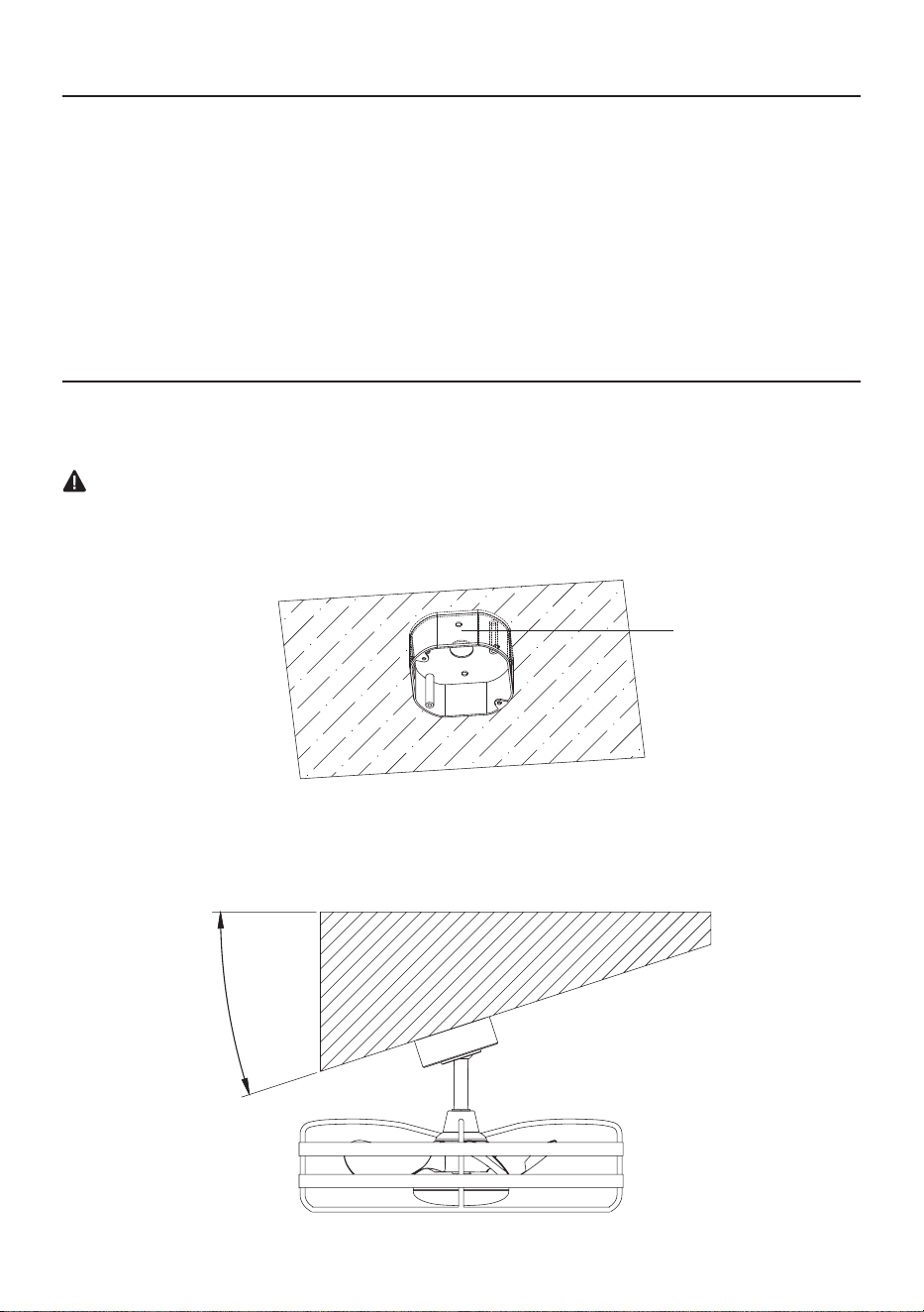
NOTA:
•
El ventilador se puede montar en un techo inclinado hasta un ángulo máximo de 15 grados.
PREPARACIÓN
11
55
°°
Caja de salida
ADVERTENCIA
• Para reducir el riesgo de incendios, descargas eléctricas o lesiones corporales, monte el ventilador
en la caja de salida marcada como “apta para soportar ventiladores de 15.9/22.7/31.8 kg (35/50/70
lb) o menos” y utilice los tornillos de montaje que se proporcionan con la caja de salida.
29
INSTRUCCIONES DE INSTALACIÓN
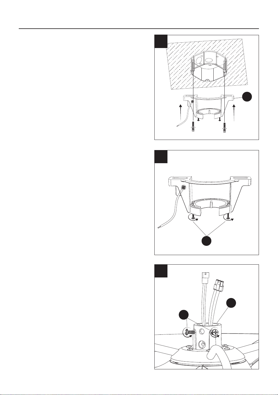
2
2. Aoje (no retire) los 2 tornillos del soporte de
montaje (SS)..
SS
1
1. Fije el soporte de montaje (A) a la caja de
salida del techo con los tornillos y las arandelas
proporcionados con su caja de salida.
NOTA: se incluyen tornillos adicionales para
la caja de conexiones #8-32 x 1” (2.54 cm),
arandelas (EE) y arandelas #10-24 x 1”
(2.54 cm) (FF) que se encuentran en la bolsa de
herramientas en caso de necesitarse.
1
A
3. Aoje los 2 tornillos de jación (QQ) de la
carcasa del motor del ventilador (G).
1
3
G
QQ
30
1
4. Si necesita instalar una varilla más larga, je
los conductores de extensión (K) incluidos a la
carcasa del motor del ventilador (G).
INSTRUCCIONES DE INSTALACIÓN
4
C
OO
PP
G
B
B
C
C
5
6
5. Retire el pasador de bloqueo (PP) y el pasador
para colgar (OO) de la varilla (C).
MM
VV
NN
6. Retire la bola para colgar (B) de la varilla (C)
al retirar los tornillos de la bola para colgar
(NN) y (VV), y al retirar el pasador cruzado
(MM); luego deslice la bola para colgar (B)
hasta retirarla de la varilla (C).
K
K
31
C
OO
PP
PP
OO
G
QQ
INSTRUCCIONES DE INSTALACIÓN
WARNING
• Si no se instala correctamente el pasador de
bloqueo de la carcasa del motor, el ventilador
podría aojarse y posiblemente caerse.
7. Pase con cuidado los conductores de la carcasa
del motor hacia arriba a través de la varilla (C).
8
8. Inserte la varilla (C) en la carcasa del motor (G).
Alinee los oricios y vuelva a instalar el pasador
para colgar (OO) y asegúrelo con el pasador
de bloqueo (PP). Apriete los tornillos de jación
(QQ).
NOTA: si siente resistencia al empujar hacia
adentro el pasador para colgar, empuje los
conductores hacia un lado.
PRECAUCIÓN
•
Para evitar daños y garantizar un funcionamiento
sin tambaleo, los tornillos de jación de la
varilla y la carcasa del motor se deben apretar
completamente hasta sentir resistencia.
1
7
C
32
10. Para volver a instalar la bola para colgar (B),
deslícela sobre la varilla (C) y vuelva a insertar
el pasador cruzado (MM) en el oricio grande.
Deslice la bola para colgar (B) hacia arriba de
modo que el pasador cruzado (MM) quede
asegurado en la ranura y asegúrese de que
los oricios de los tornillos estén alineados
correctamente, es decir, el tornillo más grande
(VV) debe alinearse con el oricio en la varilla
(C). Luego, apriete ambos tornillos, (NN) y (VV).
NOTA: asegúrese de que los conductores no
estén torcidos.
PRECAUCIÓN
•
Un tornillo ojo po
dría hacer que el ventilador se
tambalee.
INSTRUCCIONES DE INSTALACIÓN
9. Deslice la cubierta decorativa (F) sobre la varilla
(C). A continuación, deslice el anillo de la base
(E) y la base (D), ambos orientados hacia arriba,
sobre la varilla (C).
C
10
1
9
D
F
E
C
B
MM
VV
NN
VV
NN
33
B
A
A
B
TT
TT
UU
UU
12
12. Gire el ventilador ensamblado en dirección
de las manecillas del reloj hasta que la
ranura (TT) en la bola para colgar (B) se
inserte en la ranura (UU) del soporte (A) y
se asiente rmemente. La bola para colgar
(B) ya no debería poder girar si esto se hace
correctamente.
PRECAUCIÓN
•
Si no se alinea la ranura de la bola con la cuña,
se podría provocar un tambaleo.
INSTRUCCIONES DE INSTALACIÓN
11. Levante el ventilador ensamblado hasta el
techo y coloque la bola para colgar (B) en la
abertura del soporte de montaje (A).
PRECAUCIÓN
•
Para evitar dañar el ventilador, levántelo siempre
por la varilla o la carcasa del motor.
1
11
A
B
34
1
13. Inserte el receptor (H), como se muestra, en el
soporte de montaje (A).
INSTRUCCIONES DE INSTALACIÓN
13
H
A
H
15
14. Conecte los conductores de la carcasa del
motor (WW) al recibidor (H) como se muestra
y conecte los conductores de la carcasa del
motor (XX) a los conductores del recibidor
como se muestra.
H-1
15. Conecte los conductores del recibidor (H-1)
al recibidor (H) como se muestra.
XX
H
14
WW
35
ADVERTENCIA
• Todo el cableado debe realizarse de acuerdo
con el Código Eléctrico Nacional, ANSI/
NFPA 70. Si los conductores en el lugar de
instalación son de otro color de los que se
mencionan aquí, solicite a un electricista
calicado que instale este ventilador.
• El ventilador de techo debe estar conectado
a tierra. Si no hay un conductor de puesta
a tierra presente en el lugar de instalación
(por ejemplo, desde el techo), DETENGA la
instalación inmediatamente y consulte a un
electricista calicado.
AA
16
16. Conecte los conductores del techo a los conductores del recibidor de la siguiente manera:
Inserte el conductor energizado (negro) del techo en uno de los oricios libres del conector rápido
del conductor negro desde el recibidor y presione el conductor hasta el tope. Jale suavemente del
cable para asegurarse de que esté bien sujeto al conector.
Inserte el conductor neutral (blanco) del techo en uno de los oricios libres del conector rápido del
conductor blanco desde el recibidor y presione el conductor hasta el tope. Jale suavemente del
cable para asegurarse de que esté bien sujeto al conector.
Conecte todos los conductores de puesta a tierra del ventilador de techo al conductor de puesta
a tierra del techo, como se muestra a continuación, con el uso del empalme plástico (AA) que se
encuentra en la bolsa de herramientas y envuélvalo con cinta aislante. Si su techo no tiene un
conductor de puesta a tierra, consulte con un electricista calicado.
Aditamentos utilizado
Conectores de cables
x 1
AA
INSTRUCCIONES DE INSTALACIÓN
PRECAUCIÓN
• Para reducir el riesgo de descargas eléctricas,
desconecte el circuito de alimentación eléctrica
al ventilador antes del cableado. Si no cree que
su conocimiento o experiencia con cableado
eléctrico son sucientes, póngase en contacto
con un electricista calicado.
• No instale el producto en una ubicación mojada.
NOTA: después de conectar los conductores,
sepárelos de modo que los conductores de
puesta a tierra/blancos estén en un costado y
los conductores negros estén en el otro.
NOTA: opcionalmente, si tiene dicultades
para jar la base debido a los conductores,
conecte los conductores del recibidor (H-1) a
los conductores del techo antes de colocar el
recibidor (H) en el soporte de montaje (A) e
introduzca las conexiones de los conductores
en la caja de salida.
Negro Blanco De puesta
a tierra
Conductores del techo:
AA
36
D
D
E
18
18. Deslice el anillo magnético de la base (E) hacia
arriba para jarlo en la base (D).
INSTRUCCIONES DE INSTALACIÓN
1
17. Fije la base (D) al soporte de montaje (A) al
alinear los tornillos del soporte de montaje (SS)
con los oricios con forma de cerradura de
la base. Luego, gire y apriete los tornillos del
soporte de montaje (SS).
17
A
SS
37
Anclas de expansión
para tornillos de la
placa posterior del
control remoto
Anclas de expansión
para tornillos posterior
del control remoto
x 2
CC
INSTRUCCIONES DE INSTALACIÓN
19
19. SAsegure la placa posterior magnética del
control remoto (J) a la ubicación preferida en la
pared con las anclas de expansión para tornillo
(CC) y los tornillos (DD) que se encuentran en
la bolsa de accesorios del control remoto.
Una vez que la placa posterior magnética del
control remoto (J) esté montada rmemente,
coloque el control remoto (I) en la placa
posterior (J) para mantenerlo en su lugar.
Aditamentos utilizado
x 2
DD
I
J
DD
J
38
FUNCIONAMIENTO DEL VENTILADOR Y EL CONTROL REMOTO
NOTA: el control remoto utiliza 1 batería de botón CR2032 (incluida). Retire la lengüeta de plástico
de la tapa de la batería antes de usar el control remoto. Al reemplazar la batería, asegúrese de que la
tapa de la batería esté completamente cerrada (escuchará un clic).
NOTA: se ha evaluado este equipo y se ha vericado que cumple con los requisitos de exposición
a radiofrecuencias. El dispositivo se puede utilizar en condiciones de exposición portátiles sin
restricciones.
Este equipo cumple con los límites de exposición a la radiación de FCC establecidos para un entorno
no controlado.
Presione el botón para cambiar
la rotación del ventilador hacia
arriba para circular aire caliente
ascendente
Presione el botón para cambiar
la rotación del ventilador hacia
abajo para una corriente
descendente fría
Encendido y apagado
de la lámpara
Blanco ajustable
Encendido
LED
#1-6: 6 niveles de
velocidad del ventilador
Atenuador de luz hacia
arriba y hacia abajo
Presione el botón para
encender y apagar el
ventilador y la lámpara
NOTA: el ventilador y la
lámpara se encenderán
en su último estado
Presione el botón para
encender o apagar la luz
Push Presione los
botones hacia arriba o
hacia abajo para alternar
entre los 5 colores de
ambiente blanco:
luz de día fresca, luz de
día, blanco frío, blanco
cálido o blanco suave
La luz LED indicadora azul
se Iluminará al presionar
cualquier botón
Presione el botón para
encender o apagar el ventilador
Presione los botones hacia
arriba o hacia abajo
para aumentar o disminuir
el brillo
Encendido y apagado
del ventilador
Aire del ventilador
ascendente
Aire del ventilador
descendente
Control remoto SKU#:
GE37106TX
39
SOLUCIÓN DE PROBLEMAS
CUIDADO Y MANTENIMIENTO
• El movimiento natural del ventilador puede causar que se suelten algunas conexiones. Un ruido de
chasquido o traqueteo es una señal segura de que los tornillos se están aojando. Compruebe las
conexiones de soporte y la jación de los soportes y las aspas dos veces al año, y apriete todos los
tornillos según sea necesario.
• Asegúrese de desconectar el ventilador del suministro de electricidad antes de realizarle
mantenimiento o limpieza.
• Limpie el ventilador periódicamente. Utilice únicamente un paño húmedo, nunca utilice solventes y
remueva el polvo con un paño suave o un cepillo.
• Nunca necesitará engrasar el ventilador; su cojinete sellado permanentemente evitará el ruido.
• No opere el producto cuando esté dañado. Deseche el ventilador o devuélvalo a un centro de
servicio autorizado para su Inspección o reparación.
• El vataje total de la lámpara es de 17 vatios; no intente reemplazar la luz LED.
PROBLEMA SOLUCIÓN
El ventilador o
la lámpara no
encienden
1. Asegúrese de que el interruptor de pared esté encendido.
2. Compruebe todos los fusibles e interruptores de circuito.
3. Desconecte la alimentación eléctrica y asegúrese de que el cableado sea
correcto y que los conectores estén asegurados, como se muestra en los
pasos 14, 15 y 16 del ensamblaje.
4. Conrme que el control remoto esté funcionando; la luz indicadora LED debe
iluminarse cuando se presiona cualquier botón.
5. Si el ventilador o la lámpara continúan sin encender, comuníquese con un
electricista calicado. No intente solucionar usted mismo problemas de
conexiones eléctricas internas.
El ventilador
es ruidoso
1. Deje transcurrir un período de “adaptación” de 24 horas. Cualquier nivel de ruido
más alto que los niveles del ambiente deberían desaparecer durante ese tiempo.
2. Revise la caja de salida de corriente eléctrica y asegúrese de que esté bien
jada.
3. Revise todos los tornillos y las conexiones de conductores en el ventilador para
asegurarse de que estén bien rmes.
4. El uso de un regulador de luz o un control de pared no aprobados puede
provocar que el ventilador funcione de forma irregular y que produzca ruido
excesivo. Compruebe que, si está instalado, el control de pared esté aprobado
para el uso con el ventilador de techo; sin embargo, no se recomienda usar un
regulador de intensidad con el ventilador.
El ventilador
se mueve
hacia atrás y
hacia adelante
cuando
se enciende
1. Este es un procedimiento de arranque normal para ventiladores con motor
de CC. El movimiento parcial durante el arranque es el resultado de los
polos magnéticos la alineación interna del motor de CC para el correcto
funcionamiento del motor. Este diseño ahorra electricidad y permite que el
ventilador funcione mucho más silenciosamente que los ventiladores con motor
de CA estándar.
El ventilador
no mueve
mucho aire
1. Verique la dirección de las aspas del ventilador cuando esté en funcionamiento.
Si es necesario, cambie la dirección de las aspas del ventilador para garantizar
que el ventilador de techo mueva aire en la dirección deseada.
2. Asegúrese de que no haya artículos domésticos que obstruyan el ujo de aire
del ventilador de techo.
3. Verique que el ventilador de techo sea apropiado para el tamaño de la
habitación en la que está instalado.
40
GARANTÍA LIMITADA DE 3 AÑOS
SERVICIO TÉCNICO
Lo que está cubierto
Se garantiza que este producto estará libre de defectos de fábrica en las piezas y la mano de obra durante
un período de 3 años desde la fecha de compra. Todas las reclamaciones de garantía requieren un recibo
de compra.
¿Qué no cubre?
Esta garantía no incluye servicio de reparación, ajuste y calibración por mal uso, abuso o negligencia. La
reparación no autorizada o la modicación del producto o de cualquiera de los componentes suministrados
anularán esta garantía en su totalidad. Esta garantía no incluye reembolso por inconvenientes, instalación,
tiempo de instalación, pérdida de uso, servicio no autorizado o cargos de envío de devolución. Esta
garantía no se extiende a otros equipos y componentes que un cliente utiliza junto con este producto.
Si tiene alguna pregunta o problema, llame a nuestro Departamento de Servicio al Cliente al
888-251-1003, de lunes a domingo de 8 a.m. a 8 p.m., hora estándar del Este. También puede
ponerse en contacto con nosotros a través de [email protected].
No hay piezas de recambio disponibles para este producto.
Guarde su recibo de compra con fecha, se requiere para todos los pedidos de la garantía.
Impreso en China
SOLUCIÓN DE PROBLEMAS (CONTINUACIÓN)
PROBLEMA SOLUCIÓN
El ventilador tiembla
o se tambalea
1. Una tambaleo leve es normal y aceptable, por lo que no es indicativo de
un defecto. Haga funcionar el ventilador durante al menos
10 minutos antes de vericar el nivel de tambaleo.
2. Asegúrese de que la caja de salida eléctrica y el soporte para colgar
estén bien sujetos, como se muestra en el paso 1 del ensamblaje.
3. Asegúrese de que la ranura de la bola para colgar esté colocada
correctamente en la ranura del soporte; de lo contrario, gire la bola para
colgar en dirección de las manecillas del reloj hasta que la bola caiga en
la ranura, como se muestra en el paso 11 del ensamblaje.
4. Instale el kit de equilibrio (BB) incluido. Si persiste el movimiento no
deseado, simplemente cambie la ubicación del kit de equilibrio (BB) hasta
que el exceso de movimiento cese.
El control remoto
no funciona
1. Asegúrese de quitar la lengüeta de plástico del compartimiento de la
batería.
2. Asegúrese de que las baterías estén instaladas correctamente en el
control remoto.
3. Asegúrese de que el control remoto y el recibidor estén emparejados. Si
las baterías son nuevas y la luz indicadora LED está funcionando, pero el
ventilador o la lámpara aún no funcionan, es posible que el control remoto
se haya desvinculado. Para emparejar el control remoto y el ventilador,
presione el botón principal de encendido y apagado en el control remoto 3
veces en un minuto.
4. Asegúrese de que los conductores del recibidor estén conectados
correctamente al cableado de la casa y a los conductores del ventilador
de techo, como se muestra en los pasos 13, 14 y 15 del ensamblaje.