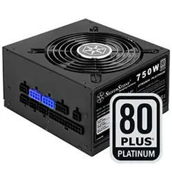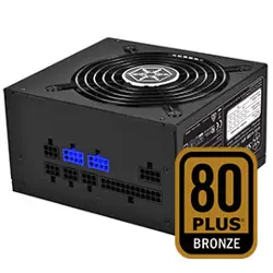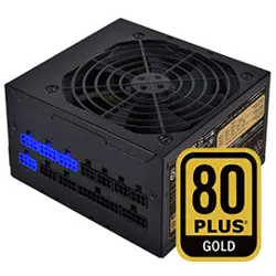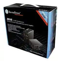

Class-leading continuous 60A Quad +12V combined output @ 50℃
Four PCI-E 6pin connector
Six Serial ATA connectors
Industrial class components
Support for ATX 12V 2.2 & EPS 12V
Active PFC
Efficiency ≧ 80%
ST75ZF
ZEUS
Raising the bar for high performance power supplies
01
1. General
This specification describes the electrical characteristics, functional and physical of a PS/2
750 watts switching power supply with Active PFC (Power Factor Correction) capabilities.
2. AC Input Characteristics
2.1 AC Input Voltage, Frequency and Current ( Rating: 100V-240Vac, 47-63Hz, 12-6A )
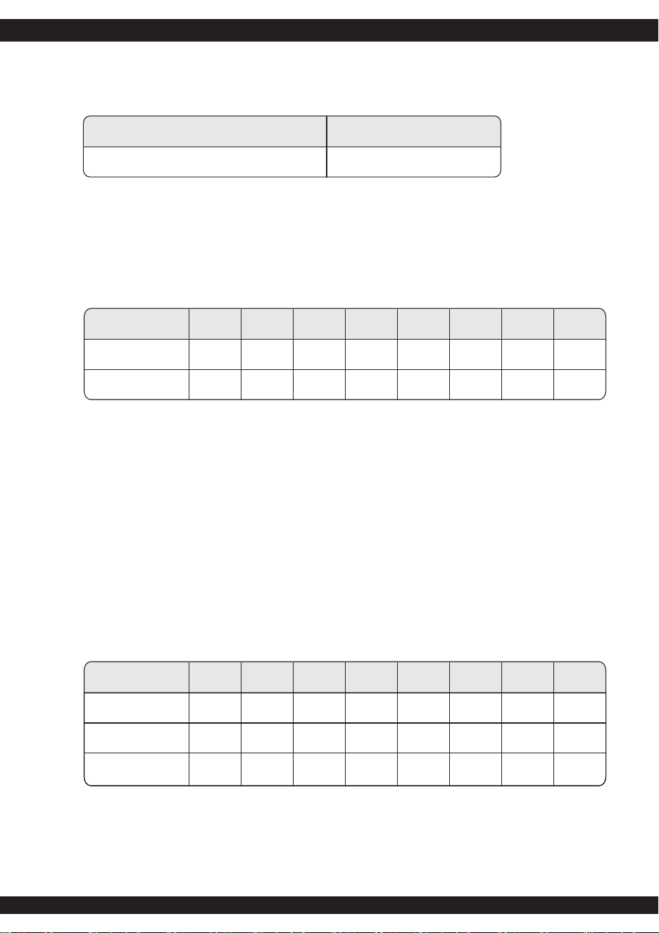
The power supply must operate within all specified limits over the input voltage range in Table 1.
Harmonics distortion of up to 10% THD must not cause the power supply to go out of specified limits.
2.2 AC Inrush Current
AC line inrush current shall not damage any component nor cause the AC line fuse to blow
under any DC conditions and with any specified AC line input voltage and frequency. Repetitive
On/Off cycling of the AC input voltage shall not damage the power supply.
2.3 Input Power Factor Correction ( Active PFC)
The power factor at full load shall be
≧
0.95 at nominal input voltage.
SilverStone Zeus ST75ZF
Switching Power Supply
With Active PFC
PS/2 750W
SPECIFICATION
Parameter RatedMinimum Maximum Max. Current
132 Vac 12A
6A
Voltage (115V) 90 Vac 100-120Vac
Voltage (230V)
Frequency
180 Vac 200-240Vac
50 / 60 Hz
264Vac
63 Hz
47 Hz
Table 1 - AC Input Voltage and Frequency
ZEUS ST75ZFZEUS ST75ZF
02
2.4 Input Current Harmonics
When the power supply is operated in 90-264Vac of Sec. 2.1, the input harmonic current drawn
on the power line shall not exceed the limits set by EN61000-3-2 class "D" standards. The
power supply shall incorporate universal power input with active power factor correction.
2.5 AC Line Dropout
An AC line dropout of 17mS or less shall not cause any tripping of control signals or protection
circuits.If the AC dropout lasts longer than 17mS the power supply should recover and meet all
turn on requirements. The power supply shall meet the regulation requirement over all rated
AC voltages, frequencies, and output loading conditions. Any dropout of the AC line shall not
cause damage to the power supply. An AC line dropout is defined as a drop in AC line to 0VAC
at any phase of the AC line for any length of time.
2.8 Electrical Fast Transient / Burst, IEC61000-4-4
No unsafe operation allowed under any condition . No user noticeable performance degradation
up to 1KV is allowed. Automatic or manual recovery is allowed for other conditions.
2.7 Surge Immunity, IEC61000-4-5
The peak value of the unidirectional surge waveform shall be 2KV for common mode and
1KV for differential mode of transient surge injection. No unsafe operation or no user
noticeable degradation is allowed under any condition. Automatic or manual recovery is
allowed for other conditions.
2.9 Electrical Discharge, IEC61000-4-2
In addition to IEC61000-4-2, the following ESD tests should be conducted. Each surface area
of the unit under test should be subjected to twenty (20) successive static discharges, at each
of the follow voltages: 2KV, 3KV, 4KV, 5KV, 6KV and 8KV.
All power supply outputs shall continue to operate within the parameters of this specification,
without glitches or interruption, while the power is operating as defined and subjected to 2kV
through 10kV ESD pulses. The direct ESD event shall not cause any out of regulation
conditions such as overshoot or undershoot. The power supply shall withstand these shocks
without nuisance trips of the Over-Voltage Protection, Over-Current Protection, or the remote
+5VDC, +12VDC shutdown circuitry.
2.6 AC Surge Voltages
The power supply shall be tested and be compliant with the requirements of IEC61000-4-5
Level 3 criteria for surge withstand capability, with the following conditions and exceptions.
The test equipment and calibrated waveforms shall comply with the requirements of
IEC61000-4-5 for open circuit voltage and short circuit current.
These input transients must not cause any out of regulation conditions, such as overshoot
and undershoot, nor must it cause any nuisance trips of the power supply protection circuits.
The surge-withstand test must not produce damage to the power supply.
The power supply must meet surge-withstand test condition under maximum and minimum
DC output load conditions.
03
Frequency Electric Field Strength
27 MHz to 500 MHz, un-modulated 3 V/m
2.10 Radiated Immunity, IEC61000-4-3
3. DC Output Specificatio
3.1 Output Current / Loading
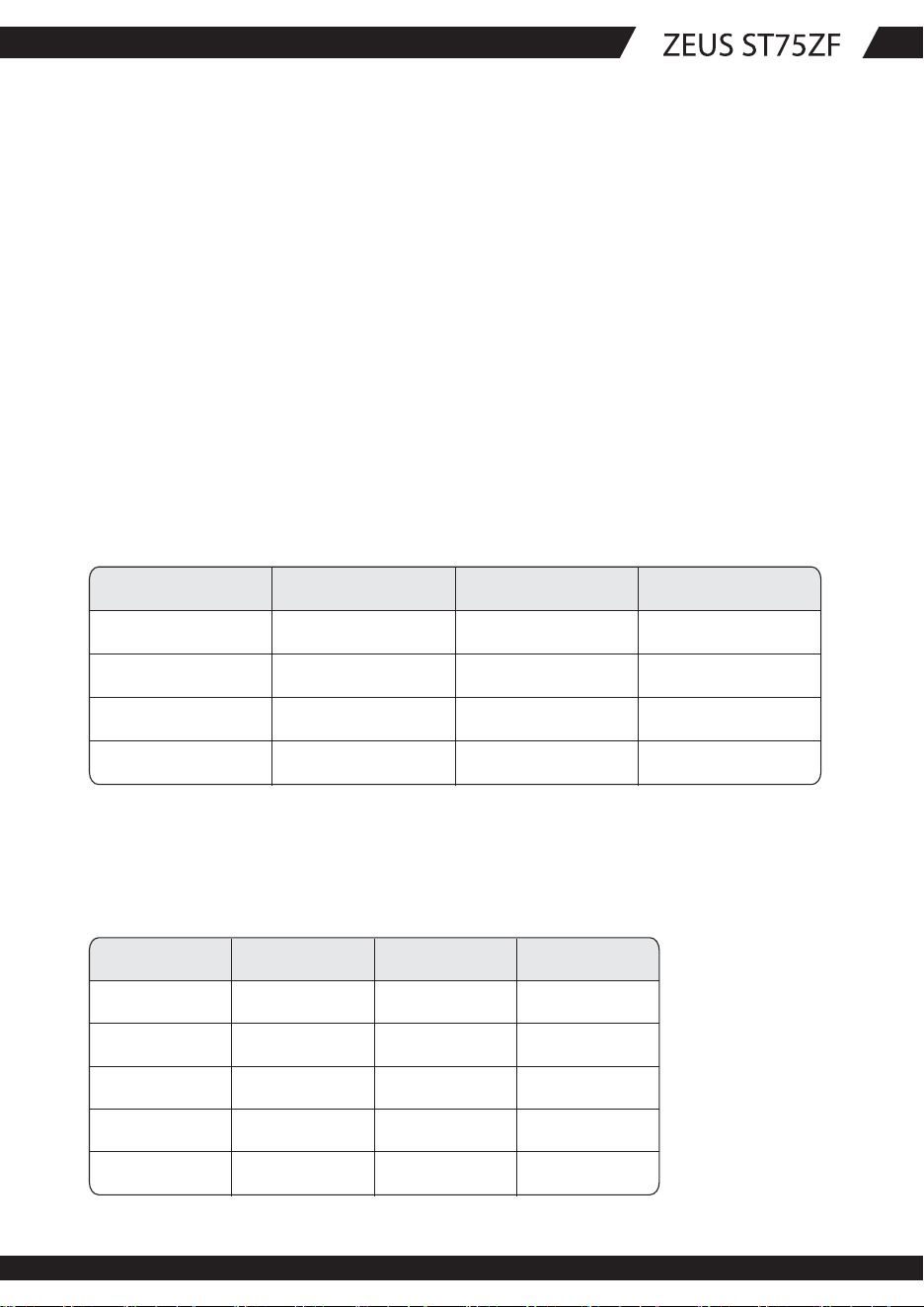
The following tables define two power and current rating. The power supply shall meet both
static and dynamic voltage regulation requirements for minimum load condition.
Note 1: The +5 & +3.3 Volt total output shall not exceed 180 W.
Note 2: Maximum continuous total DC output power should not exceed 750 W.
Note 3: Maximum continuous load on the combined 12 V output shall not exceed 60 A
Output Voltage +5V
Max. Load 30A
Min. Load 1.0A
+3.3V
24A
1.5A
+12V1
18A
0.8A
+12V2
18A
0.8A
+12V3
18A
0.5A
+12V4
18A
0.5A
-12V
0.5A
0A
+5VSB
3A
0.1A
Table 5 - Output Loads Range 1:
Output Voltage +5V
Load Reg. +/-5%
Line Reg. ±1%
+3.3V
+/-5%
±1%
+12V1
+/-5%
±1%
+12V2
+/-5%
±1%
+12V3
+/-5%
±1%
+12V4
+/-5%
±1%
-12V
+/-10%
±1%
+5VSB
+/-5%
±1%
Ripple & Noise 50mV 50mV 120mV 120mV 120mV 120mV 120mV 50mV
Table 7 - Regulation, ripple and noise
3.2 DC Voltage Regulation, Ripple and Noise
The power supply output voltages must stay within the following voltage limits when operating at
steady state and dynamic loading conditions. All outputs are measured with reference to the return
remote sense (ReturnS) signal. The +5V,+3.3V, +12V, -12V and +5VSB outputs are measure at the
power supply connectors references to ReturnS. The +5V and +3.3V is measured at its remote sense
signal (+5VS+, +3.3VS+) located at the signal connector.
ZEUS ST75ZF
04
3.3 Dynamic Loading
The output voltages shall remain within the limits specified in Table 7 for the step loading and
within the limits specified in Table 8 for the capacitive loading. The load transient repetition
rate shall be tested between 50Hz and 5kHz at duty cycle ranging from 10%-90%. The load
transient repetition rate is only a test specification.
The Δstep load may occur anywhere within the MIN load to the MAX load shown in Table 5.
Output
+5V
+12V Combine
+3.3V
ΔStep Load Size
30% of Max. Load
30% of Max. Load
Load Slew Rate
0.5 A/uS
0.5 A/uS
Capacitive Load
1,000 uF
1,000 uF
+5VSB
65% of Max. Load 0.5 A/uS 2,200 uF
25% of Max. Load 0.5 A/uS 1 uF
Table 8 - Transient Load requirements
Output
+5V
+12V
+3.3V
MIN
10
10
MAX
12,000
12,000
Units
uF
uF
-12V
10 11,000 uF
1 350 uF
+5VSB
1 350
uF
Table 9 - Capacitive Loading Conditions
3.4 Capacitive Loading
The power supply shall be stable and meet all requirements, except dynamic loading
requirements, with the following capacitive loading ranges.
Ripple and noise shall be measured using the following methods:
a) Measurements made differentially to eliminate common-mode noise
b) Ground lead length of oscilloscope probe shall be ≤ 0.25 inch.
c) Measurements made where the cable connectors attach to the load.
d) Outputs bypassed at the point of measurement with a parallel combination of
10uF tantalum capacitor in parallel with a 0.1uF ceramic capacitors.
e) Oscilloscope bandwidth of 0 Hz to 20MHz.
f) Measurements measured at locations where remote sense wires are connected.
g) Regulation tolerance shall include temperature change, warm up drift and dynamic load
05
MIN
5
MAX
70
50
400
Units
mS
mS
mS
Item
Tvout_rise
Tvout_off
Tvout_on
Description
Output voltage rise time from each main output.
(+5Vsb < 70mS)
All main output must be within regulation of each other
within this time.
All main output must leave regulation within this time
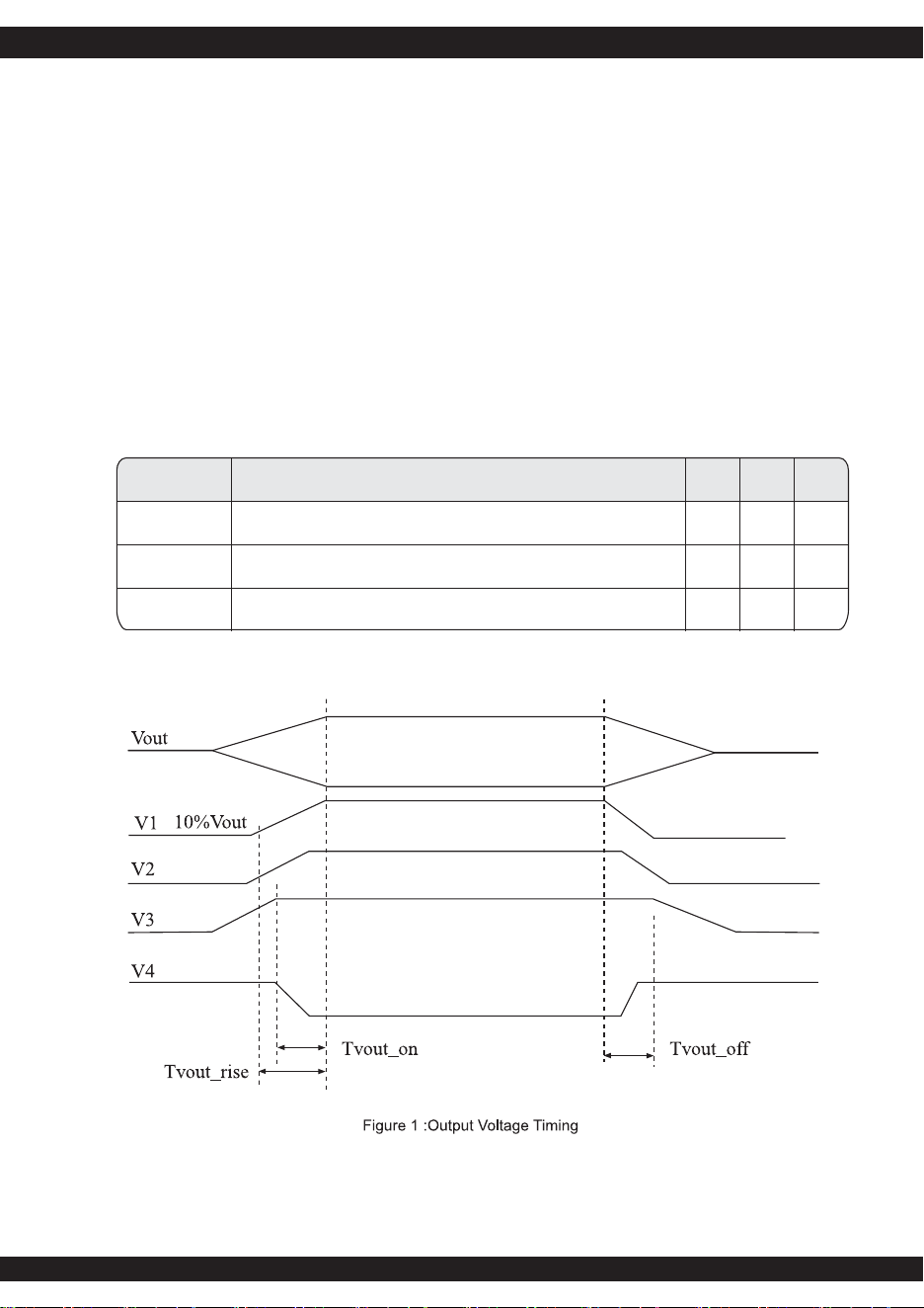
Table 10 - Output Voltage Timing
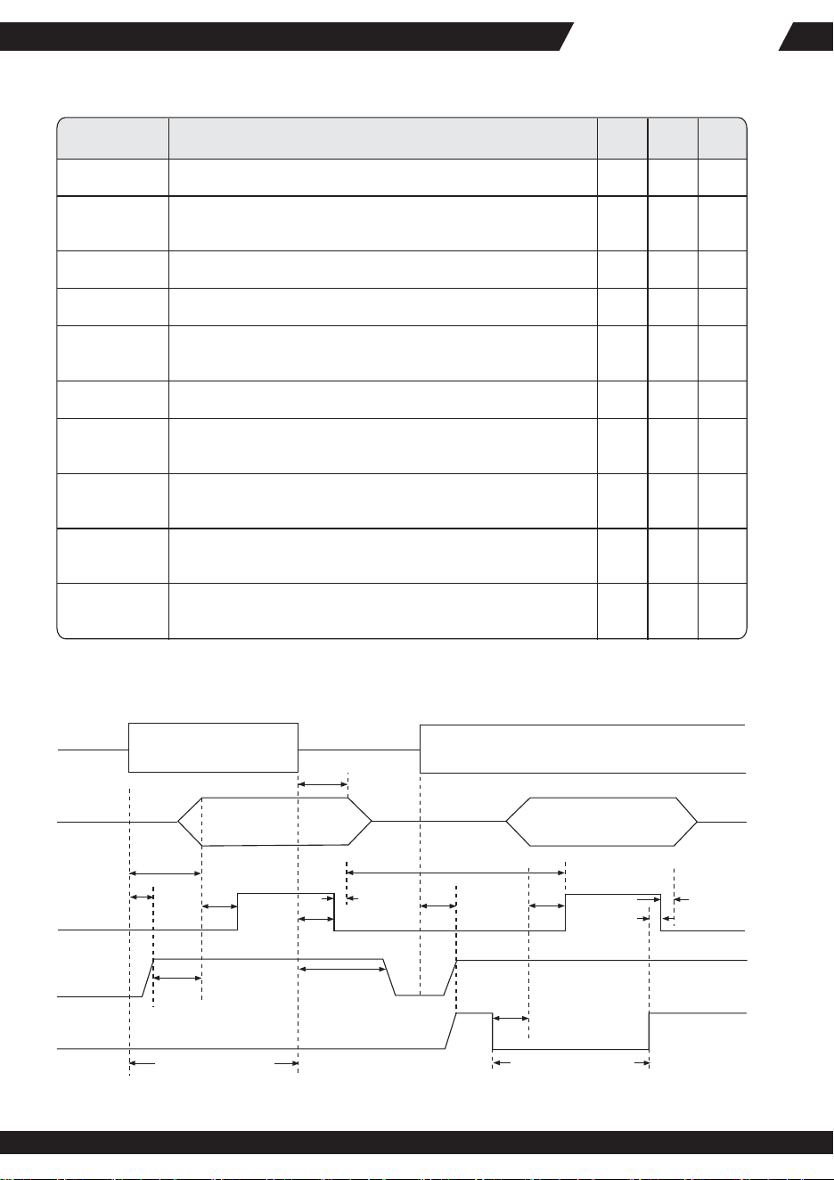
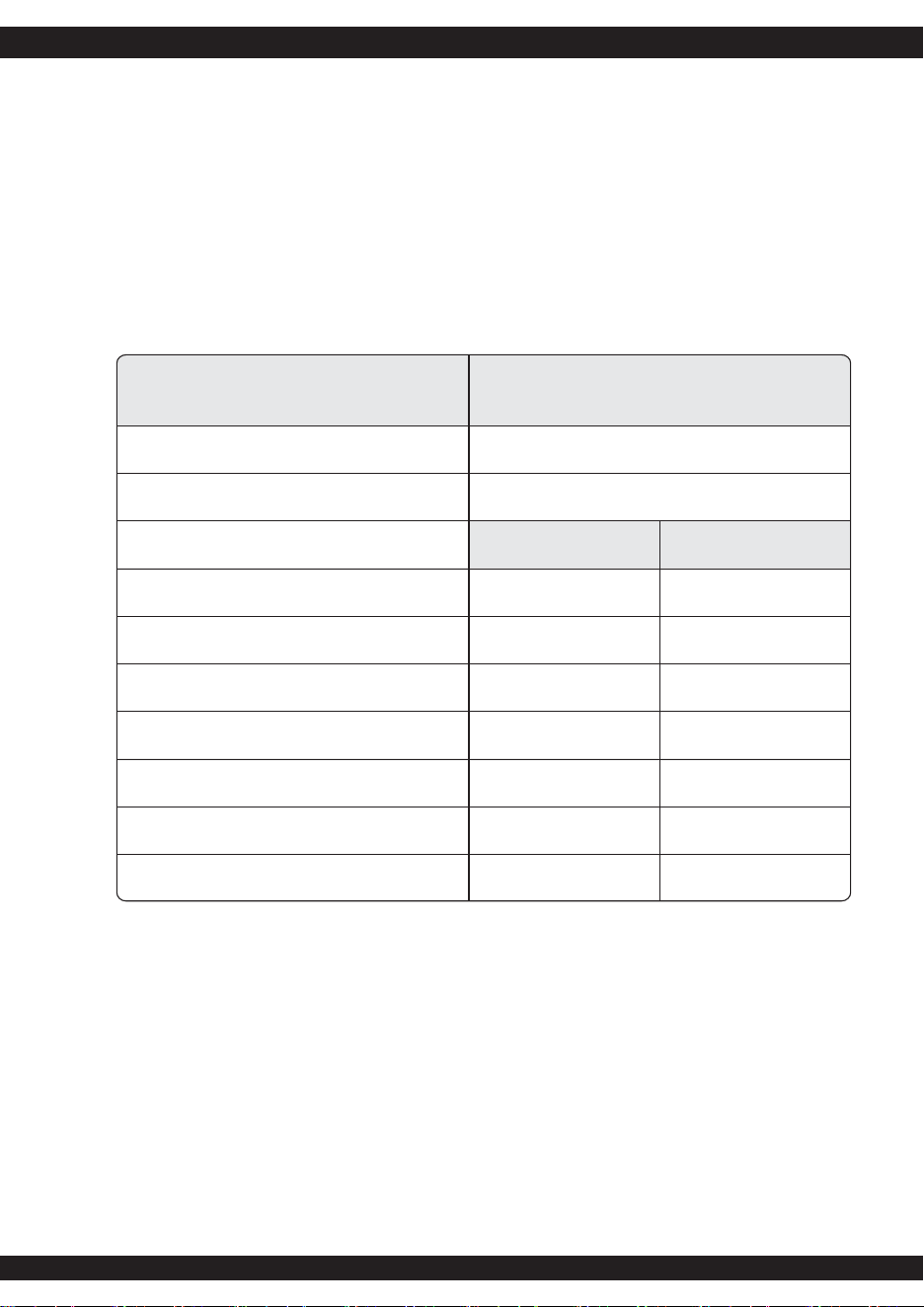
3.5 Timing Requirements
These are the timing requirements for the power assembly operation. The output voltages must
rise from 10% to within regulation limits (Tvout_rise) within 5 to 70mS. The +5V, +3.3V and
+12V output voltages should start to rise at about the same time. All outputs must rise
monotonically. The +5V output needs to be greater than the +3.3V output during any point of
the voltage rise. The +5V output must never be greater than the +3.3V output by more than
2.25V. Each output voltage shall reach regulation within 50 mS (Tvout_on) of each other
during turn on of the power supply. Each output voltage shall fall out of regulation within
400 mS (Tvout_off) of each other during turn off. Figure 1 and figure 2 show the turn On and
turn Off timing requirement. In Figure 2, the timing is shown with both AC and PSON#
controlling the On/Off of the power supply.
ZEUS ST75ZFZEUS ST75ZF
06
PWOK
+5VSB
PSON#
Vout
AC Input
Tsb_on-delay
Tac_on-delay
Tpwok_on
Tsb_vout
AC turn on/off cycle
Tsb_holdup
Min.>70mS
Figure 2 : Turn On/Off Timing
PSON turn on/off cycle
Tpson_on_delay
Tpwok_off
Tpwok_holdup
Tsb_on-delay Tpwok_on
Tpwok_off
Tpson_pwok
Tpwok_low
Tvout_holdup
AC Off AC On
Item
Tsb_on-delay
Description
Delay from AC being applied to +5VSB being within regulation.
Delay from AC being applied to all output voltages being within
regulation.
MIN MAX
1500
Units
mS
Table 11 - Turn On/Off Timing
Time all output voltage stay within regulation after loss of AC
Delay from loss of AC deassertion of PWOK.
Delay from PSON# active to output voltage within regulation
limits.
Delay from PSON# deactive to PWOK being deasserted.
Delay from output voltage within regulation limits to PWOK
asserted at turn on.
Delay from PWOK deasserted to output voltages (+5V, +3.3V,
+12V, -12V) dropping out of regulation limits.
Duration of PWOK being in the deasserted state during an off/on
cycle using AC or the PSON# signal. .
Delay from +5VSB being in regulation to O/Ps being in regulation
at AC turn on.
Tac_on-delay
Tvout_holdup
Tpwok_holdup
Tpson_on_delay
Tpson_pwok
Tpwok_on
Tpwok_off
Tpwok_low
Tsb_vout
mS
mS
mS
mS
mS
mS
mS
mS
mS
2500
18
17
5
100
1
100
50
400
50
500
1000
07
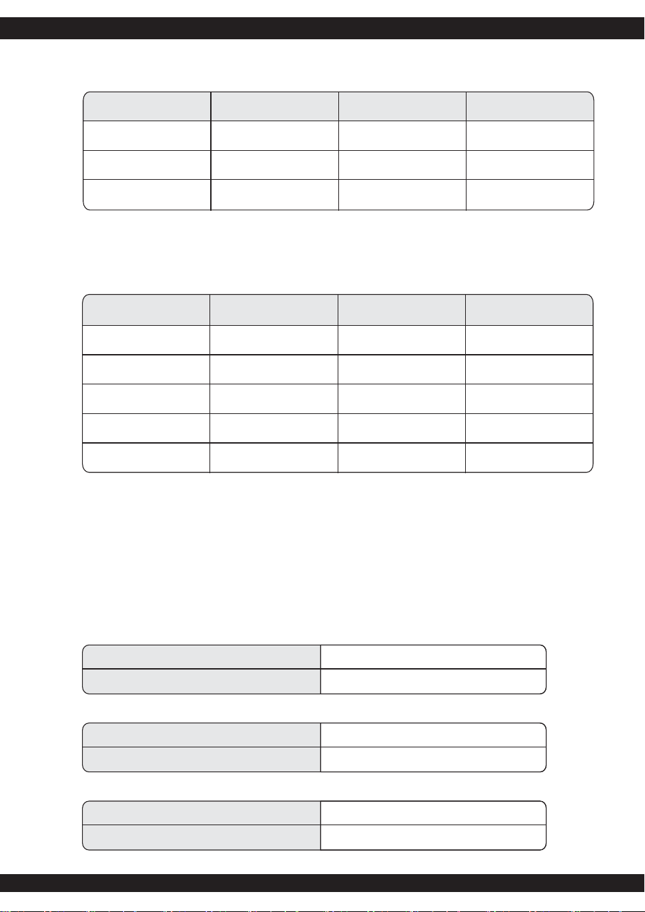
3.7 Remote On/Off Control : PSON#
The PSON# signal is required to remotely turn on/off the power supply. PSON# is an active
low signal that turns on the +5V, +3.3V, +12V and -12V power rails. When this signal is not
pulled low by the system, or left open, the outputs(except the +5VSB and Vbias) turn off.
This signal is pulled to a standby voltage by a pull-up resistor internal to the power supply.
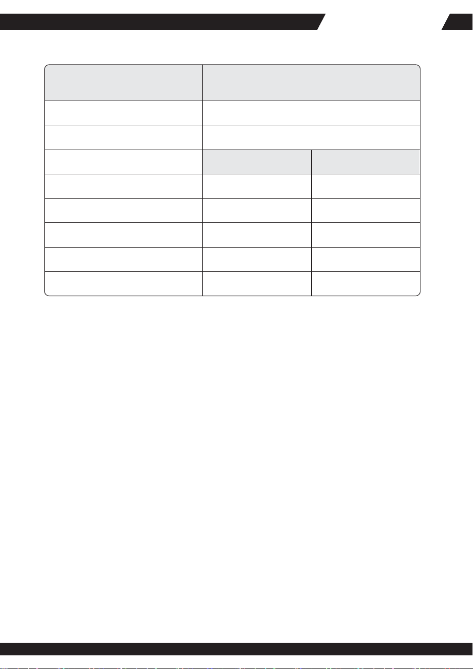
3.6 Power Good Signal : PWOK
PSOK is a power OK signal and will be pulled HIGH by the power supply to indicate that all
the outputs are within the regulation limits of the power supply. When any output voltage falls
below regulation limits or when AC power has been removed for a time sufficiently long so
that power supply operation is no longer guaranteed, PWOK will be deasserted to a LOW state.
See for a representation of the timing characteristics of PWOK. The start of PWOK delay time
shall inhibited as long as any power supply output is in current limit.
Signal Type
Open collector/drain output from power supply.
Pull-up to VSB located in power supply.
PWOK = High
PWOK = Low
Logic level low voltage, Isink = 4mA
Logic level high voltage, Isource = 200μA
Sink current, PWOK = Low
Source current, PWOK = High
PWOK delay: Tpwok_on
PWOK rise and fall time
PWOK down delay : Tpwok_off
Power OK
Power is Not OK
MIN
0V
2.4V
100mSec
2mSec
MAX
0.4V
5.25V
4mA
2mA
1000mSec
100μSec
200mSec
Table 12 - PWOK Signal Characteristics
ZEUS ST75ZFZEUS ST75ZF
08
Signal Type
Accepts an open collector/drain input from the system.
Pull-up to VSB locted in power supply
PSON# = Low
PSON# = Open
Logic level low (Power supply ON)
Logic level low (Power supply OFF)
Source current, Vpson = Low
Power up delay: Tpson_on_delay
PWOK delay : Tpson_pwok
Power ON
Power OFF
MIN
0V
2.0V
5mSec
MAX
1.0V
5.25V
4mA
400mSec
50mSec
Table 13 - PWOK Signal Characteristics
3.8 Overshoot at Turn-on /Turn-off
Any output overshoot at turn on shall be less than 10% of the nominal output value. Any overshoot
shallrecover to within regulation in less than 10ms.
3.9 Efficiency
The minimum power supply system efficiency shall be
≧
80% with maximum efficiency up to 86%,
measured at nominal input voltage 115 V or 230 V and full loading.
3.10 +5VSB (Standby)
The +5VSB output is always on (+5V Standby) when AC power is applied and power switch is
turned on. The +5VSB line is capable of delivering at a maximum of 3.0A for PC board circuit to
operate.
4.1 Over Current Protection
This power supply shall have current limit to prevent the +5V, +3.3V, and +12V outputs from
exceeding the values shown in table 14. The current limit shall not trip under maximum continuous
load or peak loading as described in Table 5. The power supply shall latch off if the current exceeds
the limit. The latch shall be cleared by toggling the PSON# signal or by cycling the AC power. The
power supply shall not be damaged from repeated power cycling in this condition. The -12V and
+5VSB outputs shall be shorted circuit protected so that no damage can occur to the power supply.
Protection circuits inside the power supply shall cause only the power supply's main outputs to
shutdown. If the power supply latches off due to a protection circuit tripping, either a AC cycle
OFF for 15 sec, or PSON# cycle HIGH for 1 sec must be able to restart the power supply.
4. Protection
09
Voltage
+5V
+3.3V
Minimum
110%
110%
Maximum
150%
150%
Shutdown Mode
Latch Off
Latch Off
+12V
110% 150% Latch Off
Table 14 -Over Current protection
4.2 Over Voltage Protection
Power supply shall shut down in latch off mode when the output voltage exceeds the over
voltage limit.
Voltage
+5V
+3.3V
Minimum
+5.7V
+3.9V
Maximum
+6.5V
+4.5V
Shutdown Mode
Latch Off
Latch Off
+12V1,2,3,4,5 +13.3V
-13.3
5.7
+14.5V
Latch Off
Table 15 -Over Voltage protection
-12V
5VSB
-14.5
6.5
Latch Off
Latch Off
4.3 Short Circuit Protection
The power supply shall shut down in a latch off mode when the output voltage is short circuit.
4.4 No Load Operation
When the primary power is applied, with no load on any output voltage, no damage or
hazardous conditions shall occur.
5. Environmental Requirements
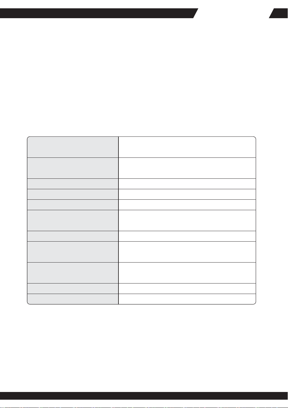
Operating Temperature Range:
0℃ ~ 50℃ (32℉~ 122℉)
Non-Operating Temperature Range: -40℃ ~ 70℃ (-40℉~ 158℉)
5.1 Temperature
Operating Humidity Range:
20% ~ 90%RH non-condensing
Non-Operating Humidity Range: 5% ~ 95%RH non-condensing
5.2 Humidity
Operating Altitude Range:
Sea level to 10,000 ft
Non-Operating Altitude Range: Sea level to 40,000 ft
5.3 Altitude
ZEUS ST75ZFZEUS ST75ZF
10
5.4 Mechanical Shock
The power supply (non-operating) shall not be damaged during a shock of 50G with an 11
mS half sin wave, non-operating. The shock to be applied in each of the orthogonal axes.
5.5 Vibration (Operating and Non-operating)
The power supply shall be subjected to a vibration test consisting of a 10 to 300 Hz sweep at
a constantacceleration of 2.0g for duration of one (1) hour for each of the perpendicular axes
X, Y and Z, 0.1 octave/minute. The output voltages shall remain within specification.
6.2 AC Input Leakage Current
Input leakage current from line to ground will be less than 3.5mA rms. Measurement will be
made at 240 VAC and 60Hz.
6. Agency Requirements
6.1 Safety Certification.
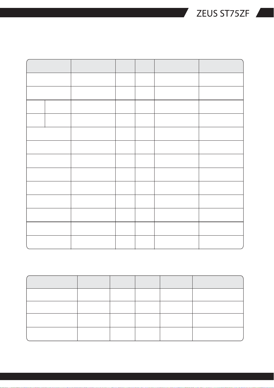
Product Safety:
Table 16 -Safety Certification
RFI Emission:
UL 60950 2000Edition, IEC60950, 3
rd
EditionEU
Low Voltage Directive(73/23/EEC) (CB)TUV, CCC
PFC Harmonic:
Flicker:
Immunity against:
-Electrostatic discharge:
-Radiated field strength:
-Fast transients:
-Surge voltage:
-RF Conducted
-Voltage Dips and Interruptions
FCC Part15 (Radiated & Conducted Emissions)CISPR
22,3
rd
Edition/ EN55022 Class B)
EN 61000-3-2
EN55024: 1998
-IEC 61000-4-2 Min. 4kV contact discharge
Min. 8kV air discharge
-IEC 61000-4-3 Min. 10V/m
-IEC 61000-4-4 Min 2kV AC input lines
Min 1kV on data lines
-IEC 61000-4-5 Min 2kV common mode
Min 1kV differential mode
-IEC 61000-4-6
-IEC 61000-4-11
EN 61000-3-3

11
6.3 Production Line Testing
100% of the power supply production must have the following test performed. Each power
shall be marked indicating the testing was done and passed. Typically this is done by stamping
or labeling the power supply with "Hi-pot test OK".
6.4 Hi-Pot Testing
Each power supply must be Hi-pot tested according UL and TUV requirements, Minimum
typical testing voltage for Hi-pot testing are 1500Vac or 2121Vdc. However depending on the
power supply design the testing voltage May be higher. If higher the power supplies shell be
at the higher value.
6.5 Ground Continuity Testing
UL and TUV require that each power supply ground is tested, to ensure there is continuity
between the ground inlet of the power supply and the power supply chassis. This can be
performed with an ohm meter, or an electronic circuit that lights up and illustrates the ground
has continuity.
Based on EN50116, ERG or TUV require that each power supply ground id tested with a
25Amp ground test.
7. Reliability
7.1 Mean Time Between failures (MTBF)
The MTBF of the power supply shall be calculated utilizing the Part-Stress Analysis method
of MIL217F or Bellcore RPP. The calculated MTBF of the power supply shall be greater than
100,000 hours under the following conditions:
Full rated load
120V AC input
Ground Benign
25℃
Technical information in this specification is subject to change without notice.
The revision of specification will be marked on the cover.
8. Connections
8.1 AC Input Connector and DC Wire Harness and Connector Requirements
Please refer to the attachment
9. Physical Characteristics Size
9.1 Power Supply Dimension: 150.0mm(W) x 86.0mm(H) x 180.0mm(D)
ZEUS ST75ZF
12
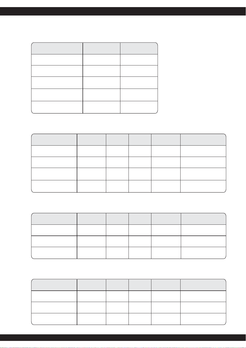
9.2 Pin definition
16AWG wire Signal Pin Pin Signal 16AWG wire
Orange
Orange(22AWG)
Blue
Black
Green(20AWG)
Black
Black
Black
N/C
Red
Red
Red
Black
(18AWG)
+3.3V
+3.3Vsense
-12VDC
COM
PS-ON
COM
COM
COM
N/C
+5VDC
+5VDC
+5VDC
COM
13
13
14
15
16
17
18
19
20
21
22
23
24
1
2
3
4
5
6
7
8
9
10
11
12
+3.3V
+3.3V
COM
+5VDC
COM
+5VDC
COM
PWRGOOD
+5Vsb
+12V3
+12V3
+3.3V
Orange
Orange
Black
Red
Black
Red
Black
Grey (20AWG)
Purple(18AWG)
Yellow
Yellow
Orange
4PIN molex connector (HDD) 4PIN floppy connector (FDD)
18 AWG wire Signal
Yellow/Black stripe +12V3
Black COM
Pin
1
2
Pin
1
2
22AWG wire
Red
Black
Black COM 3 3
Signal
+5VDC
COM
COM Black
+12V3 Yellow44+5VDCRed
M/B 24PIN connector
13
EPS 12V 8PIN Connector
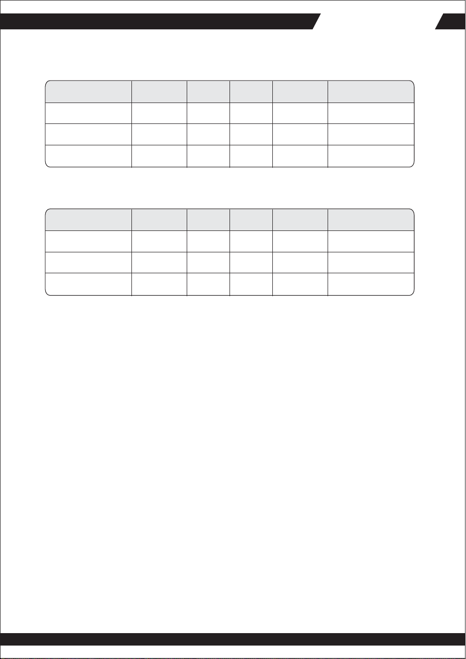
18AWG wire Signal
Yellow +12V1
Yellow +12V1
Pin
5
6
Pin
1
2
18AWG wire
Black
Black
Yellow +12V2 7 3
Signal
COM
COM
COM Black
COM Black48+12V2Yellow
EPS 12V 6PIN Connector
18 AWG wire Signal
Orange +3.3V
Orange +3.3V
Pin
1
2
Pin
4
5
18AWG wire
Black
Black
Yellow +12V3 3 6
Signal
GND
GND
Yellow
+12V3
SATA connector
18AWG wire Signal
Orange +3.3V
Black GND
Pin
5
4
Red +5V 3
2GNDBlack
Yellow +12V2 1
18 AWG wire Signal
Yellow +12V4
Yellow +12V4
Pin
1
2
Pin
4
5
18AWG wire
Black
Black
Yellow +12V4 3 6
Signal
GND
GND sense
GND Black
6PIN PCI Express Connector #1 & #2
ZEUS ST75ZFZEUS ST75ZF
14
18 AWG wire Signal
Yellow +12V2
Yellow +12V2
Pin
1
2
Pin
4
5
18AWG wire
Black
Black
Yellow +12V2 3 6
Signal
GND
GND sense
GND Black
6PIN PCI Express Connector #3
18 AWG wire Signal
Yellow +12V3
Yellow +12V3
Pin
1
2
Pin
4
5
18AWG wire
Black
Black
Yellow +12V3 3 6
Signal
GND
GND sense
GND Black
6PIN PCI Express Connector #4

April , 2006