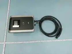

iM3C Series
Level 2 AC EV Charging station
VISION Pro
UM15200-2-2025

VISION Level 2 AC EV Charging station User Manual
IMPORTANT SAFETY INSTRUCTIONS
WARNING- When using electric products, basic precautions should always be
followed, including the following. This manual contains important instructions for
Models iM3C-09K6B, iM3C-11K5B, and iM3C-19K2B that shall be followed during
installation, operation, and maintenance of the unit.
1. Read all the instructions before using this product.
2. This device should be supervised when used around children.
3. Do not put fingers into the electric vehicle connector.
4. Do not use this product if the flexible power cord or EV cable is frayed, has broken
insulation, or any other signs of damage.
5. Do not use this product if the enclosure or the EV connector is broken, cracked,
open, or shows any other indication of damage.
6. Indicate the ambient temperature rating, -35°C to 50°C.
7. "CAUTION" and the following or equivalent: "To reduce the risk of fire, connect
only to a circuit provided with @ amperes maximum branch circuit overcurrent
protection in accordance with the National Electrical Code, ANSI/NFPA 70, and the
Canadian Electrical Code, Part I, C22.1."
Note (@)
Model
Current Rating
iM3C-09K6B
40A
iM3C-11K5B
48A
iM3C-19K2B
80A
VISION Level 2 AC EV Charging station User Manual
CONSIGNES DE SÉCURITÉ IMPORTANTES
AVERTISSEMENT- Lors de l'utilisation de produits électriques, des précautions de base
doivent toujours être suivies, y compris les suivantes. Ce manuel contient des
instructions importantes pour les modèles iM3C-09K6B, iM3C-11K5B, et iM3C-19K2B
qui doivent être suivies pendant l'installation, l'utilisation et la maintenance de l'unité.
1. Lisez toutes les instructions avant d'utiliser ce produit.
2. Cet appareil doit être surveillé lorsqu'il est utilisé à proximité d'enfants.
3. Ne mettez pas les doigts dans le connecteur du véhicule électrique.
4. N'utilisez pas ce produit si le cordon d'alimentation flexible ou le câble EV est
effiloché, a une isolation cassée ou tout autre signe de dommage.
5. N'utilisez pas ce produit si le boîtier ou le connecteur EV est cassé, fissuré, ouvert
ou montre toute autre indication de dommage.
6. Indiquez la température ambiante, de -35° C à 50 ° C.
7. "MISE EN GARDE" et ce qui suit ou équivalent: "Pour réduire le risque
d'incendie, connectez uniquement à un circuit équipé d'une protection maximale
contre les surintensités de circuit de dérivation de @ ampères conformément au
Code national de l'électricité, ANSI / NFPA 70 et au Code canadien de l'électricité,
Partie I, C22.1. "
Noter (@)
Modèle
Note actuelle
iM3C-09K6B
40A
iM3C-11K5B
48A
iM3C-19K2B
80A

VISION Level 2 AC EV Charging station User Manual
1. ABBREVIATIONS
S/N
Abbreviations
Description
1
IEC
International Electrotechnical Commission
2
EV
Electrical Vehicle, this can be BEV (battery EV) or PHEV (plug-in hybrid
EV)
3
EVSE
Electric Vehicle Supply Equipment [IEC61851-1]
4
OBC
On-board charger (of an EV)
5
kW
Kilo Watt (unit of Power)
6
A
Ampere (unit of Current)
7
V
Volt (unit of Voltage)
8
Hz
Hertz (unit of Frequency)
9
LCD
Liquid Crystal Display
10
LED
Light-emitting Diode
11
RFID
Radio Frequency Identification
12
CMS
Central Management System, manages EVSE and has the information
for authorizing users for using its EVSE.
13
OCPP
Open Charge Point Protocol
A standard open protocol for communication between EVSE and a
Central System and is designed to accommodate any type of charging
technique. (www.openchargealliance.org)
14
HMI
Human-Machine Interface
15
CCID
Charging Circuit Interrupting Device
16
GM/I
Ground Monitor Interrupter
17
GFCI
Ground Fault Circuit Interrupter
18
PnC
Plug and Charger

VISION Level 2 AC EV Charging station User Manual
2. SAFETY NOTES
2.1. Safety signs used
The following warning signs, mandatory signs and information signs are used in this manual, on and
in the AC EV Charger.
Les panneaux d'avertissement, panneaux obligatoires et panneaux d'information suivants sont utilisés
dans le manuel d'utilisation, sur et dans la station de charge EV:
CAUTION: Warning of electrical hazards.
This sign is intended to alert the user that severe personal injury or substantial
property damage can result if the device is not operated as requested.
MISE EN GARDE: Avertissement de risques électriques.
Ce signe est destiné à alerter l'utilisateur que des blessures graves ou des
dommages matériels importants peuvent survenir si l'appareil n'est pas utilisé
comme demandé.
ATTENTION: Warning of a danger spot or dangerous situation.
This sign is intended to alert the user that minor personal injury or material damage
can result, if the device is not operated as requested.
ATTENTION: Avertissement d'un point de danger ou d'une situation
dangereuse.
Ce signe est destiné à alerter l'utilisateur que des blessures légères ou des
dommages matériels peuvent survenir si l'appareil n'est pas utilisé comme
demandé.
CAUTION: Do not touch by hands in case of ESD.
Indicates the possible consequences of touching electrostatically sensitive
components.
MISE EN GARDE: En cas de décharge électrostatique, ne touchez pas à la main.
Indique les conséquences possibles du contact avec des composants sensibles à
l'électricité statique.

VISION Level 2 AC EV Charging station User Manual
No access for unauthorized persons.
Pas d'accès pour les personnes non autorisées.
Use protective footwear.
Utilisez des chaussures de protection.
Must wear a safety helmet.
Doit porter un casque de sécurité.
Indicates important texts, notes, or tips.
Représente un texte, une note ou un indice important.
2.2. Installation
Safety protection must be done when installing the EV Charger.
Une protection de sécurité doit être effectuée lors de l'installation de
la station de charge EV.
▷
Installation must be carried out by personnel with professional qualification,
otherwise there is a risk of electric shock.
L'installation doit être effectuée par du personnel qualifié, faute de quoi il y a
un risque d'électrocution.
▷
It shall be installed in the place without violent vibration and impact, and
placed vertically to facilitate ventilation.
Il doit être installé à l'endroit sans vibrations et chocs violents, et placé
verticalement pour faciliter la ventilation.
▷
It shall be installed on noncombustible materials, or there is a risk of fire.
Il doit être installé sur des matériaux incombustibles, ou il existe un risque
d'incendie.
▷
Do not drop any foreign objects, especially metal objects, into the inside of
the Charger or there is a risk of fire.
Aucun objet étranger, en particulier un objet métallique, ne doit être placé
dans le chargeur sans risque d 'incendie.
VISION Level 2 AC EV Charging station User Manual
2.3. Maintenance
▷
The lead nose of the Charger must be securely attached or there is a risk of
damaging the equipment.
Les fils du chargeur doivent être solidement connectés, faute de quoi le
matériel risque d'être endommagé.
Personnel must always use protective footwear when maintenance
work.
Le personnel doit toujours porter des chaussures de protection lors
des travaux de maintenance.
▷
It is recommended that routine safety inspection visits to Charger be
conducted at least once a week.
Il est recommandé que le chargeur fasse l'objet d'un contrôle de sécurité au
moins une fois par semaine.
▷
Do not put inflammable, explosive, or combustible materials, chemicals,
combustible steam, and other dangerous goods near the Charger, otherwise
there is a risk of fire.
Il est interdit de placer des substances dangereuses telles que des matières
inflammables, explosives ou inflammables, des produits chimiques, des
vapeurs inflammables à proximité des chargeurs, faute de quoi il y a un risque
d'incendie.
▷
Keep the charging adapter clean and dry and wipe with a clean, dry cloth if
soiled. Do not touch the Charger with your hand when charged.
Maintenir l 'adaptateur de charge propre et sec, en cas de saleté, et l' essuyer
avec une toile sèche propre.Ne touche pas le chargeur avec la main.

VISION Level 2 AC EV Charging station User Manual
2.4. Operation
▷
Strictly forbidden for minors or persons of restricted capacity to approach the
Charger to avoid injury.
Il est strictement interdit aux mineurs ou aux personnes dont la capacité de
mouvement est limitée d'avoir accès au chargeur pour éviter les blessures.
▷
Forced charging is strictly forbidden when the electric vehicle or Charger fails.
La charge forcée est interdite en cas de panne du véhicule électrique ou du
chargeur.
▷
Electric vehicle can only be charged with the engine off and stationary. Do not
charge in rainy and thunderous weather.
Le véhicule électrique ne peut être rechargé que si le moteur est éteint et
statique.Il ne faut pas recharger les jours de pluie et les orages.
▷
It is strictly prohibited to use the Charger when the charging adapter or
charging cables are defective, cracked, worn, broken or the charging cables is
exposed. If you find any, please contact the supplier in time.
L'utilisation de chargeur est strictement interdite lorsque l'adaptateur de
charge ou le câble de charge présente des défauts, des défauts, des défauts,
de l'usure, de la rupture ou de la nudité.En cas de découverte, veuillez
contacter le fournisseur en temps voulu.
VISION Level 2 AC EV Charging station User Manual
3. STANDARDS COMPLIANCE
3.1. Standard(s) for safety
Conformer to UL 2594, 3
rd
, Ed., Issue Date: 2022-12-15.
3.2. AC Level 2 Charging
According to SAE J 1772, VISION (the maximum output current is 80 A) was designed for AC
Level 2 charging.
3.3. Charging mode and connection
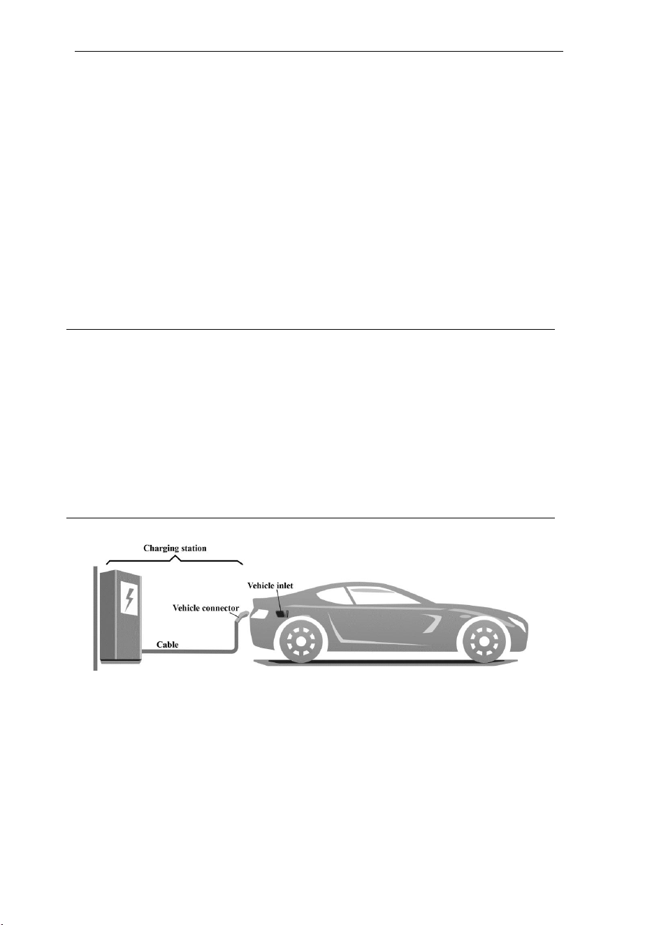
According to IEC 61851-1, the Charging mode of VISION is Mode 3, and charging connection is
the Case C.
Mode 3:
a method for the connection of an EV to an AC EV supply equipment permanently
connected to an AC supply network, with a control pilot function that extends from
the AC EV supply equipment to the EV.
Case C:
Connection of an EV to a supply network utilizing a cable and vehicle connector
permanently attached to the EV charger.
Fig. 3-1 Schematic diagram of CASE C connection

VISION Level 2 AC EV Charging station User Manual
3.4. Charging interface
The VISION charging plug complies with SAE J1772 / IEC 62196-2 Type 1 and SAE J3400 (NACS)
standards.
VISION can be optionally equipped with a Type 1 female plug and charging cable, which is only
suitable for charging electric vehicles with a Type 1 charging socket (vehicle inlet).
Alternatively, VISION can be configured with a NACS charging cable, compatible with electric
vehicles that feature a NACS charging socket (vehicle inlet).
Fig. 3-2-2 Schematic diagram of NACS interface
(a) Socket
(b) Plug
Fig. 3-2-1 Schematic diagram of Type 1 interface
VISION Level 2 AC EV Charging station User Manual
4. PRODUCT INFORMATION
4.1. General
Welcome to use Level 2 AC EV charger VISION by our company.
4.1.1. Shape & dimensions
The shape & dimensions of VISION shown as Fig. 4-1.
Fig. 4-1 The shape & dimensions of VISION
4.1.2. Model number definition
The model number definition of charger follows the rules as shown in Fig. 4-3.
i
M3C
-□□□□
B
B: Vision Pro
Rated output power
09K6: 9.6kW
11K5: 11.5kW
19K2: 19.2kW
M3C: Wallbox shell code
i: Injet New Energy
Fig. 4-2 Model number definition
VISION Level 2 AC EV Charging station User Manual
4.2. Specifications
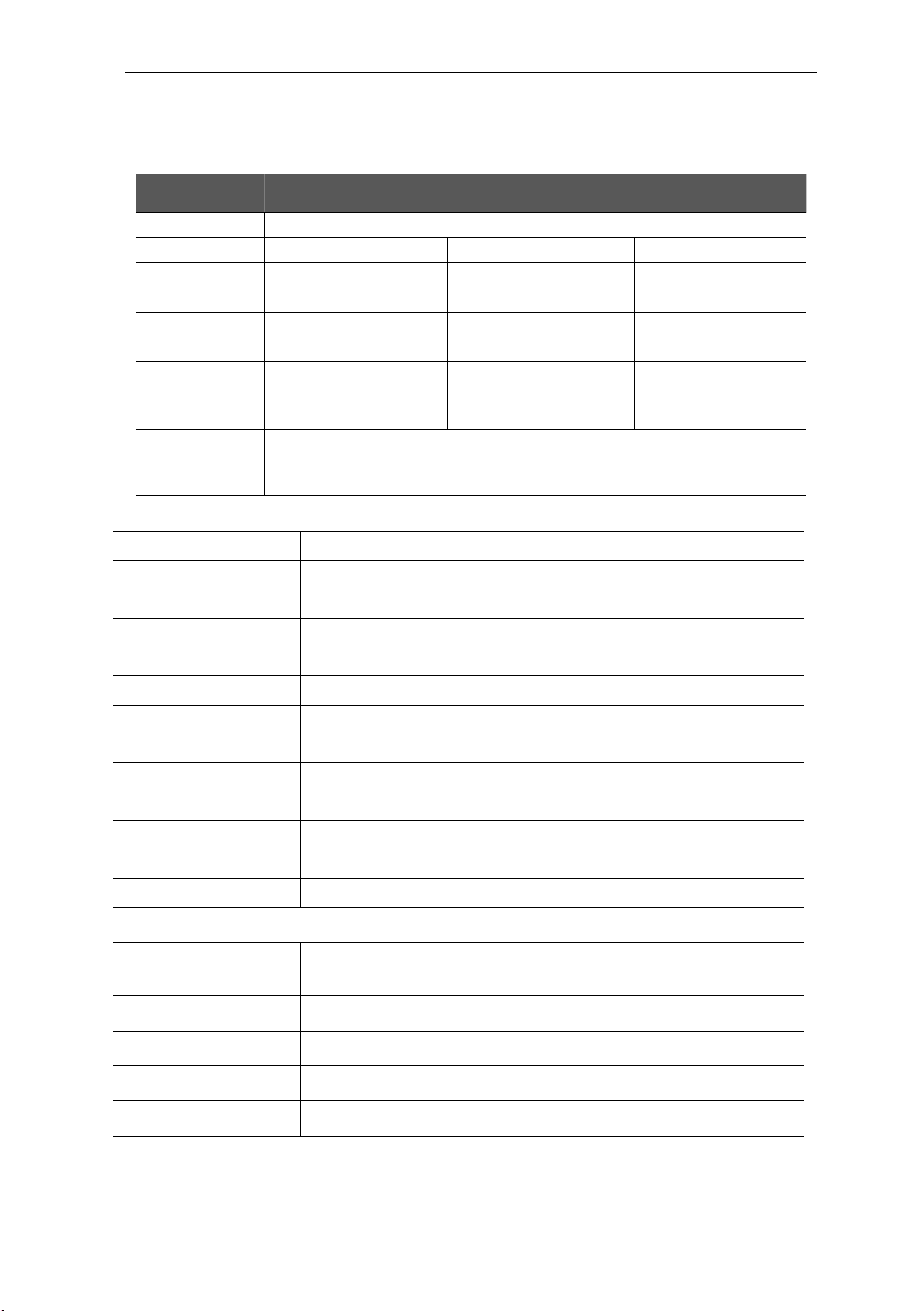
4.2.1. Electrical specifications
Model Number
iM3C-09K6B
iM3C-11K5B
iM3C-19K2B
Rated Voltage
240V/208V (AC Level 2 Charging), 50/60Hz
Rated Current
40A
48A
80A
Rated Power
9.6kW
(@240VAC)
11.5kW
(@240VAC)
19.2kW
(@240VAC)
Recommended
MCB/MCCB
Dedicated circuit
50A,2-Pole
Dedicated circuit
63A,2-Pole
Dedicated circuit
100A,2-Pole
Recommended
Input cable
Cable: 3×6 AWG,
copper.
Cable: 3×4 AWG,
copper.
Cable: 3×2 AWG,
copper.
Charging
interface
IEC 62196-2, Type 1 or SAE J3400 (NACS) plug with 5m cable
Note: That cord extension sets are not be used.
4.2.2. Functional description
Charging Mode
Mode 3
Charging Control
Remote: “APP-controlled”
Local: “Plug-and-Play”, “Card-controlled” or “POS-controlled”
Display Screen
4.3-inch LCD touch screen (display charging current, voltage, energy,
charging time, state & fault information, etc.)
Indicator Lights
Multi-color atmosphere lights
Communication
interface
WIFI (2.4GHz/5GHz), Ethernet (RJ-45), Bluetooth5.0, 4G(Optional)
RS 485, USB,PLC
Communication
protocol
OCPP 1.6J full + security 3, Modbus RTU,Modbus TCP,ISO 15118
Safety Protection
Surge protection, over temperature, over/under voltage, over current,
ground protection
CCID built-in
Yes, CCID 20
4.2.3. Mechanical parameters
Mounting
Wall-mounted or pole-mounted (mounting pole is optional)
Net Weight
7.6kg
Dimension
H×W×D = 404mm × 284mm × 160mm
Color & Material
Black and Grey, PC
Enclosure rated
Type 4
VISION Level 2 AC EV Charging station User Manual
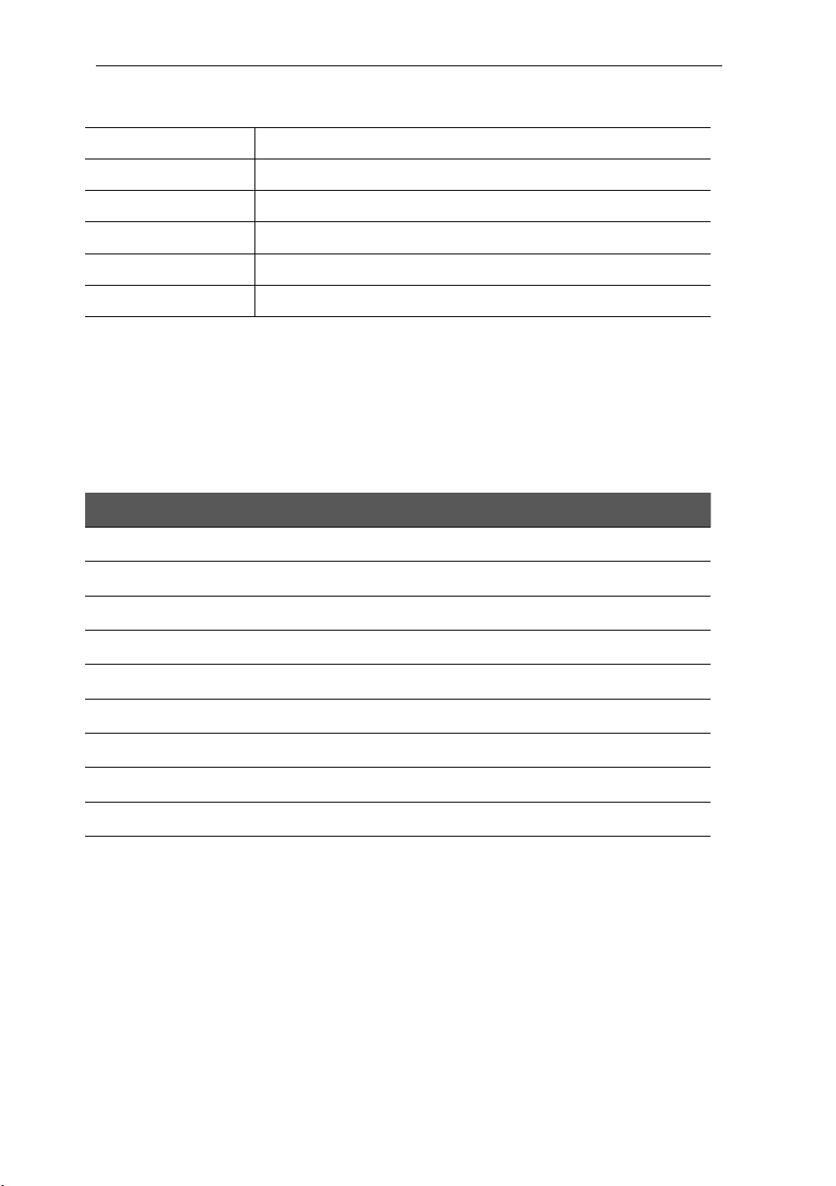
4.2.4. Ambient conditions
Altitude
≤ 2000m (Safety design ≤3000m)
Storage temperature
-40 ~ 80℃
Operation temperature
-35 ~ 50℃ *
Relative humidity
≤ 98%RH, no water droplet condensation
Vibration
< 0.5G, no acute vibration and impaction
Installation location
Indoor or outdoor, good ventilation, no flammable, explosive gases
When the charging station is powered on at temperatures below -20°C, the display screen may initially appear black. This is a normal
phenomenon. After being powered on for approximately 10 minutes, the screen should return to normal.
5. INSTALLATION
5.1. Unpacking
5.1.1. Packing list
Package
Quantity
AC EV Charging station
1 pc
Empty socket
1 pc
RFID card
2 pcs
Wall-mounting accessories (including A+B+C+D as Fig. 5-1 shown)
1 set
Quick Guide
1 pc
Quality certificate
1 pc
Torx screwdriver
2 pc
RS485 Waterpoof connecter
1 pc
Wire terminal
3 pcs

VISION Level 2 AC EV Charging station User Manual
Fig. 5-1 Wall-mounting accessories
5.1.2. Inspection & confirm
When unpacking, please carefully confirm the following points:
Whether the accessories are missing according to the packing list.
Whether there is any damage during transportation.
Whether the model and specification of the machine's nameplate are consistent with the order
requirements.
5.2. Prepare
When transporting or moving the EV charger, pay attention to the following points to ensure
product safety:
To ensure the long-term stable
operation of the product, it is
▷ If any damage or missing parts are found, please do not start the machine, and
contact the supplier as soon as possible.
▷ Please keep the packing box and packing materials 1 month for future handling.
▷ The paper packaging is recyclable.
▷ This product is electrical equipment. It should be handled with care to avoid
violent vibration and impact.
▷ The charger shall not be transported by dragging the charging connector and
the charging cable.
VISION Level 2 AC EV Charging station User
Manual
recommended to avoid installing
chargers in extreme weather as far as
possible, especially low or high
ambient temperature may affect the
installation effect due to thermal
expansion and cold contraction.
Space requirement: When the charger
is fixed on the wall, the minimum space
requirements are shown in Fig. 5-2.
Fig. 5-2 Minimum space requirements for wall
mounting
It is suggested that the charger should be installed in a place with good ventilation, no direct
sunlight and shelter from wind and rain. To ensure good ventilation condition, you should mount
the charger vertically and leave enough space.
Tools for installation
Prepare the following tools at least before installing the VISION AC EV Charging Station.
No.
Tools’ Name
Schematic Picture
Main Uses
1
Multimeter
Check the electrical connection
and measure the voltage
2
Electric Impact drill
Drill fixing holes in the wall
3
Wrench
Fastening bolt
4
Diagonal plier
Cut the cable

VISION Level 2 AC EV Charging station User Manual
5
Wire stripper
Peeling cables
6
Crimping plier
Pressed cable terminal
7
Cross screwdriver
Fastening screw
8
Torx screwdriver
Fastening screw
5.3. Installation steps
5.3.1. Drill fixing holes
Drill 4 holes with diameter of 6mm and depth of at least 50mm on the wall as installation map.
Fig. 5-3 Installation map

VISION Level 2 AC EV Charging station User Manual
Install the Mounting Accessory-B Φ6 Expansion tube into the 4 holes.
Fig. 5-4 Install expansion tube
5.3.2. Fix positioning plate
Use 4 screws Mounting Accessory-A to install the positioning plate D on the wall.

VISION Level 2 AC EV Charging station User Manual
Fig. 5-5 Fix the plate
Make sure the bubble in the attached spirit level is positioned at the center during installation.
Fig. 5-6 Spirit level
5.3.3. Fix the Charging station
First step: Hang the charger onto mounting accessory D;

VISION Level 2 AC EV Charging station User Manual
Second step: Use the installation accessory-C M4 screw to fix the charger.
Fig. 5-7 Fix the charger
5.3.4. Open the cover
Unfasten the button M3 screw with T10 Torx screwdriver as step [A],
Pry off the front cover from the hole on the side with slotted screwdriver as step [B].
Fig. 5-8 Open the front cover
Unfasten the six screws and remove the terminal cover.
VISION Level 2 AC EV Charging station User Manual
Fig. 5-9 Open the terminal cover
5.3.5. Wiring and additional features
Wiring
Pass the prepared power cable through the input cable interface, and connect each wire to the
corresponding input terminals labeled LA, LB, and GND as shown in Fig. 5-10.
Ensure that the cables are correctly connected before powering on; otherwise, it may result in
equipment damage, electrical faults, or safety hazards.
Suggestions on cable size selection as below:
Sr No.
Product
Rated
current
Recommended
MCB/MCCB
Suggestion Cable size
1
iM3C-09K6B
40A
Dedicated circuit
50A,2-Pole
Cable: 3x8 AWG, copper
2
iM3C-11K5B
48A
Dedicated circuit
63A,2-Pole
3
iM3C-19K2B
80A
Dedicated circuit
100A,2-Pole
Cable: 3x6 AWG, copper
NOTE: Please use waterproof fittings, 1-inch conduit only.

VISION Level 2 AC EV Charging station User Manual
Fig. 5-10 wiring
4G SIM card installation(Optional)
Vision can be optionally equipped with a 4G cellular network for connecting to the CMS. You can insert a
4G NANO SIM card into the SIM card slot as shown in fig 5-11.
Fig. 5-11 Functional Interfaces

VISION Level 2 AC EV Charging station User Manual
Payment terminal(Optional)
Vision can be optionally equipped with a payment terminal, currently supporting the Nayax UNO-mini
POS device.
Fig. 5-12 Payment terminal
Power Supply and Communication
The UNO-mini can be powered and communicate with the Vision charger via a USB 2.0 connection,as
shown in fig 5-11.
Installation
When the UNO-mini is selected as an option, it will be pre-installed on the wiring cover. Please open the
terminal cover carefully to avoid damaging the internal wiring.
Fig. 5-12 Payment terminal
VISION Level 2 AC EV Charging station User Manual
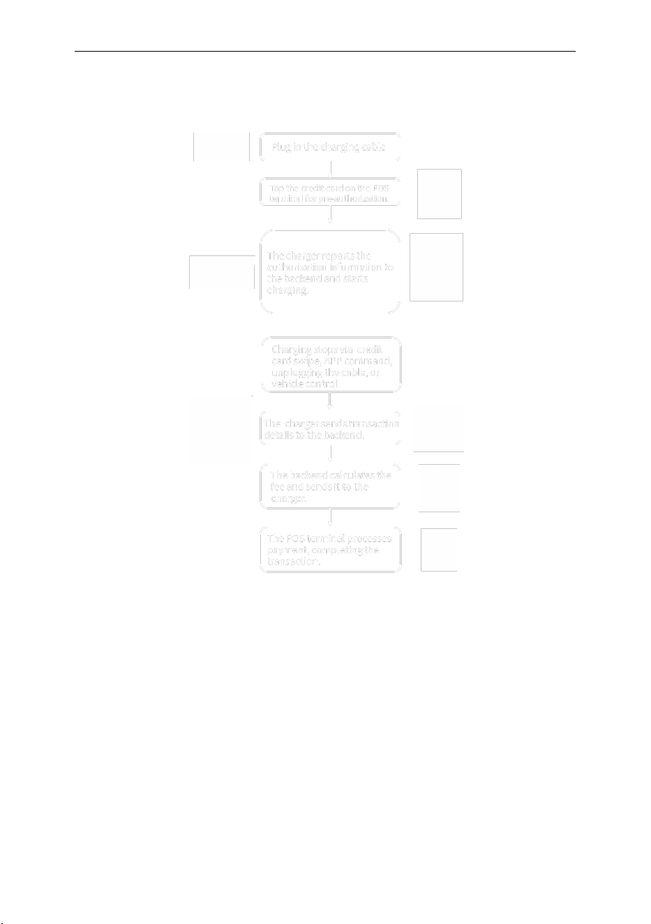
Payment Process
The UNO-mini operates in a local communication mode. The payment process is as follows:
Fig. 5-10 Payment process
Additional Features
Vision is equipped with reserved RS485, CAN, AI, and DI interfaces. These can be used as needed and
should be connected to the control device via the corresponding communication interface.
For more information, please contact your service provider.
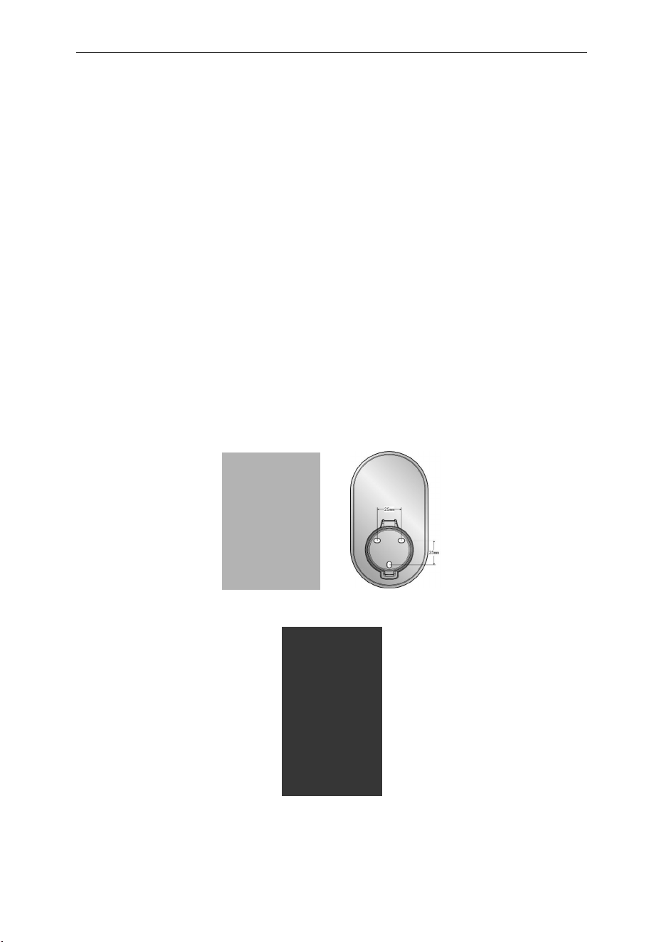
5.3.6. Fix the Cover
Step A: Close the terminal cover and fasten the six screws;
Step B: Install the front cover on the charger
Step C: Fasten the button screw.
VISION Level 2 AC EV Charging station User Manual
Fig. 5-9 Fix the Cover
5.4. Empty socket
The VISION AC EV charger can be configured with either a Type 1 or NACS charging connector.
When the charger is in standby mode, please insert the charging plug into the empty socket to protect
the charging connector.
Use expansion screws to securely fix the empty socket in a suitable position next to the charging station.
Fig. 5-10-1 Type 1 Empty socket
Fig. 5-10-2 NACS Empty socket

VISION Level 2 AC EV Charging station User Manual
6. OPERATION
6.1. Power on
After the charger has been installed and confirmed, switch on the power supply. The light and screen
lights up and the charger switches to standby state.
6.2. Human-Machine Interface
6.2.1. Overview
As shown in Fig. 6-1, VISION is configured with multiple human-machine interfaces.
1
Touch screen
②
LED indicator
③
RFID reader
④
Contactless Symbol for POS
⑤
Input cable
⑥
Ethernet interface
⑦
Communication interface
⑧
Charging cable
Fig. 6-1 HMI of VISION
6.2.2. LCD screen
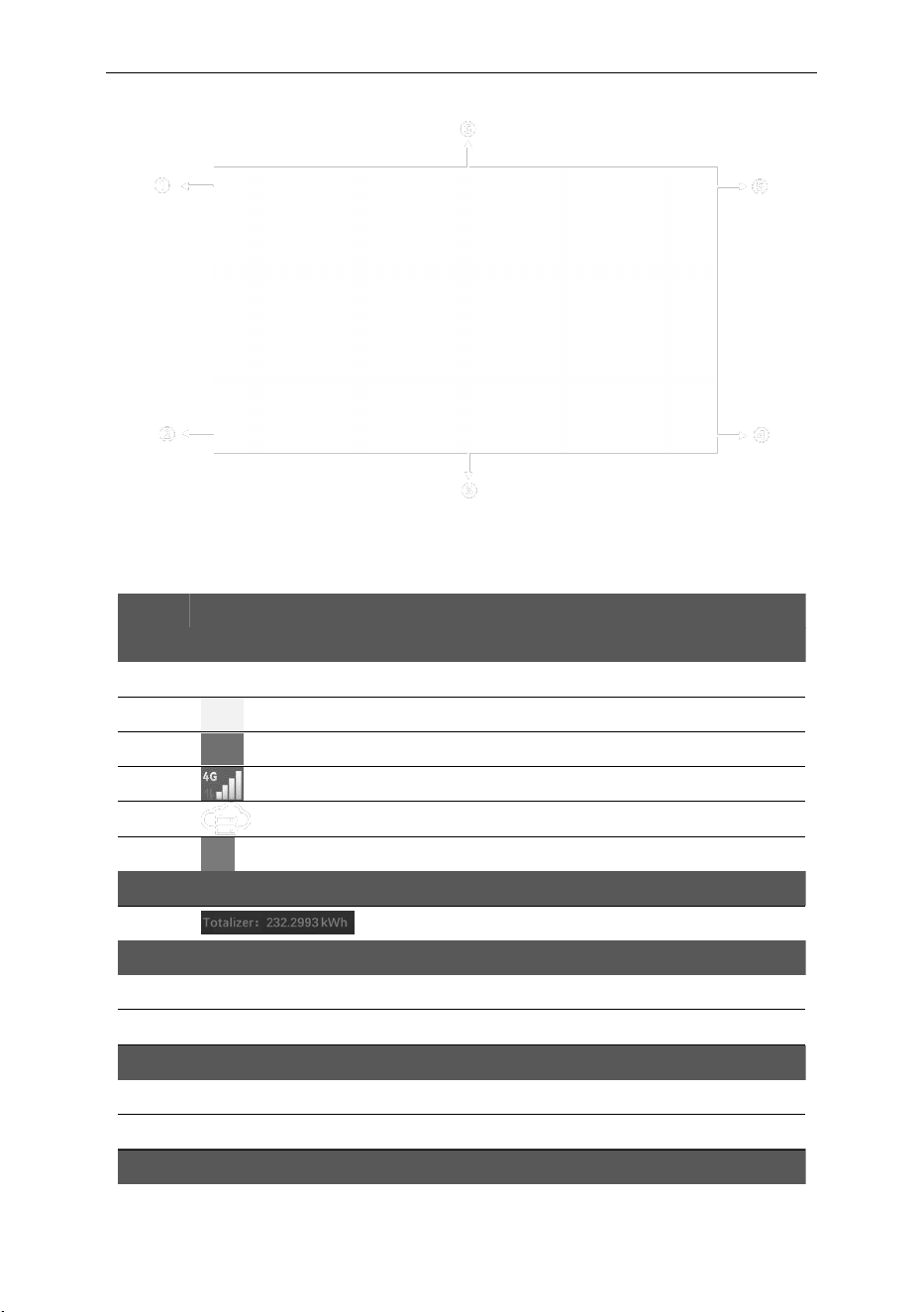
Vision config a 4.3-inch LCD touch screen, which is mainly used to display various status information and
set parameters of the charger shown as Fig. 6-2.
Icons or instructions in each display area
VISION Level 2 AC EV Charging station User Manual
Fig. 6-2 Display of icons and instructions
In Fig. 6-2, there are some areas to display icons or instructions, with the specific meanings as follows:
NO.
Icon
Connotation
Area ①
1
No icon
Off-line or no network
2
Connect to router via WIFI
3
Connect to router via Ethernet
4
Connect to internet via 4G
5
Connect to OCPP server
6
Recurring Reservation Indicator
Area ②
7
The totalizer of the charging station
Area ③
8
Pricing
9
Language
Area ④
10
Error code
11
CP voltage
Area ⑤

VISION Level 2 AC EV Charging station User Manual
12
Setting
13
The firmware version of the charging station
Area ⑥
14
The maximum rate of energy transfer and type of current
As shown in Fig. 6-3, the LCD screen displays multiple types picture in normal charging process.
Standy
Connected
Starting
Charging
Finished
Fig. 6-3 Display of normal charging
If the charging process fails or the equipment fails, the picture displayed on the LCD screen is shown in
Fig. 6-4.

VISION Level 2 AC EV Charging station User Manual
Fig. 6-4 Display of fault state
Payment terminal user interface(Optional)
VISION can be optionally equipped with a payment terminal.
To start charging with a credit card, tap the “ ” button on the connection status screen to
enter the POS UI, then follow the on-screen instructions to swipe the card and initiate charging.
Similarly, to stop charging with a credit card, tap the “ ” button on the charging end screen
to access the POS UI, and swipe the card as instructed to complete the charging session.
The status UI of the payment terminal is shown as Fig. 6-5.
Start charging by POS
Stop charging by POS
Idle for POS
Ready to read card
VISION Level 2 AC EV Charging station User Manual
Card read successfully
Authorizing
Approved
Declined
Fig. 6-5 Display of POS
6.2.3. LED indicator
The LED indicator on the panel is used to indicate the status of the charger and the various combinations
of indicators are described as below.
No.
Light Strip
Colors
Light Strip Status
Connotation
1
Green
On
Standby state
2s on, 2s off continuous alternation
Network configuration in progress
2
Blue
2s on, 2s off continuous alternation
Charging cable plugged in
On
Charging state
3
Red
Fast twinkle
Ground fault status
6.2.4. RFID reader
In general, the charger is equipped with RFID card reader as standard, and the charging process can be
started and stopped by using the RFID card (shown as Fig. 6-6) configured with the host. The special
customized card swiping function is not separately described here.
VISION Level 2 AC EV Charging station User Manual
Fig. 6-6 RFID card
6.3. Config the parameters
6.3.1 Config parameters Via offline configuration page
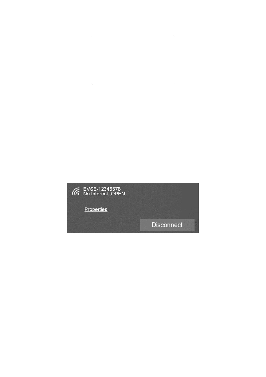
Step 1: connect to Wi-Fi hotspot
Restart the charging station;
Enable the Wi-Fi function on your phone or laptop;
Look for the Wi-Fi hotspot named “EVSE-XXXXXXXX” (where XXXXXXXX represents the last
8 characters of the charging station’s serial number);
Connect to the hotspot with password 12345678.
Fig. 6-7 Connect the AP
Step 2: login to configuration page
Open your phone or laptop’s browser and fill in the website “192.168.4.1”.
Fill the default password and login;
The default password is the last 8 characters of the second line of the QR code. Please check the
QR code sticker on the side of the device, For example, the password is the 8 characters in the red
box: ‘72f79d77’.

VISION Level 2 AC EV Charging station User Manual
Fig. 6-8 The default password
Step 3: Config your EV Charger
Please change the password upon your first login. As shown in Fig. 6-8 set the parameters on this page.
Fig. 6-9 Login Web & Main Menu Interfaces

VISION Level 2 AC EV Charging station User Manual
WLAN Setting Interface
Fig. 6-10 WLAN Setting Interface
LAN Setting Interface
Users can select the on/off state of the DHCP function as needed.
Fig. 6-11 LAN Setting Interface

VISION Level 2 AC EV Charging station User Manual
4G/OCPP/About Setting Interfaces
Fig. 6-12 4G/OCPP/About Setting Interfaces
General Setting Interface
Users can set the screen brightness, screen off time, and other parameters according to demand, After
setting, click the “SAVE”button to save the settings, and click the “Reboot” button to restart charging
station.
Fig. 6-13 General Setting Interface

VISION Level 2 AC EV Charging station User Manual
Fig. 6-14 General Setting Interface
DLB Setting Interface
There are three options available for DLB Mode: "Solar Logic & DLB", "Power Share" and "Customer
logic". Product configuration can be selected according to the corresponding function
Fig. 6-15 DLB Setting Interface
6.3.2 Config parameters Via touch screen

VISION Level 2 AC EV Charging station User Manual
Step 1: Enter login interface
Click the button to enter the settings login interface.
Fig. 6-16 Enter Login interface
Step 2:Login to setting page
The default login password is the same as that for the configuration page. For details, please refer to
Section 6.3.1.
Fig. 6-17 Login setting interface
Step 3:View and configure
Users can configure the charging station or view its information.
VISION Level 2 AC EV Charging station User Manual
Fig. 6-18 Set parameters to config the EV charger
6.3.3 Config parameters Via WE E-Charge application.
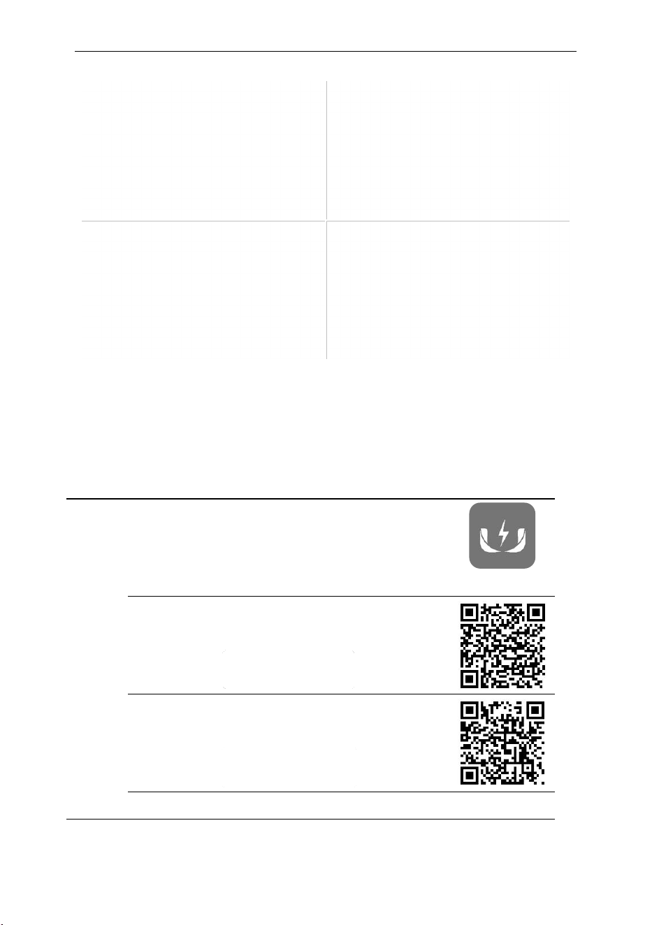
Step 1: Download the WE E-Charge
Use phone’s camera or browser to scan the corresponding QR code to download the APP. Or search in
Google Play or App Store.
▷ If you want to scan QR code on the screen to start charging,
please download and install the
WE E-Charge
APP on your
smart phone.
WE E-Charge
▷ For Android phone, search “WE E-Charge” in Google Play
Store or scan the QR code on the right to install APP.
▷ For iPhone, search “WE E-Charge” in APP Store or scan
the QR code on the right to install APP.
▷ The user manual of APP please refer to the FAQ of APP.

VISION Level 2 AC EV Charging station User Manual
Step 2: Log-in
Follow the instructions on the screen to log in to the APP, then scan the QR code, connect the charger.
Fig. 6-19 Log-in instructions
Step 3: Configuration WLAN via Bluetooth
a) Click the configuration button, the App will connect to the Bluetooth and enter the WLAN
configuration interface.
b) Tap the network button, select the WLAN to which the charging station needs to be connected,
and then enter the password
c) Wait for the charging station to connect to the network after configuration finishing.

VISION Level 2 AC EV Charging station User Manual
Fig. 6-20 Configuration WLAN via Bluetooth
6.4. Start Charging
Park your EV into place, turn off, and put the EV under braking.
Pick off the charging connector form empty socket of EV charger.
As shown in Fig.6-21, plug the charging connector into the AC charging socket of the EV.
Fig. 6-21 Plug into EV socket
For the charging control mode of “Plug-and-Play” the charging will start automatically after EV
connector plug in.
For the charging control mode of “Card-controlled”, “POS-controlled” or “APP-controlled”,
you can control charging process by swipe RFID card, credit card or APP after charging connector
plug in.
6.5. Stop Charging
The charging station will automatically stop when the electric vehicle is fully charged.
For the mode of “Plug-and-play” charging station, you can manually stop charging.
For the mode of “Card-controlled” or “POS-controlled”, swipe your RFID card or credit card
again.

VISION Level 2 AC EV Charging station User Manual
For the mode of “scan QR code” charging station, click the stop button on your APP, the
charging will stop.
When the charging is end, please unplug the charging connector and plug back to the empty
socket of charging station.
Fig. 6-22 Unplug the charging plug
6.6. Abnormally stop charging
Forced fault stop: A fault stops initiated by the onboard charger of vehicle.
Automatic fault stops: A fault stops initiated by the charger.
VISION Level 2 AC EV Charging station User Manual
7. FAULT HANDLING AND MAINTENANCE
7.1. Fault Handling
The charger is automatically protected in the event of the fault. The fault information and handling
methods are as follows.
Fault code
Handling method
Fault code 11:
CP voltage anomaly
Check the connection of charging plug and socket.
Disconnect and reconnect the charging plug.
Fault code 13:
Undervoltage input
Check whether input plug is reliably connected.
Check whether the input voltage is abnormal.
Fault code 14:
Overvoltage input
Check whether the input voltage is abnormal.
Fault code 15:
Over-temperature protection
Check whether the charger is covered or installed in a
high temperature environment.
Fault code 16:
Metering fault
Power off and restart the device.
Fault code 17:
Leakage protection
Check whether the charging plug, charging cable and
EV socket are damaged or wet.
Power off, disconnect and reconnect the charging plug
and restart.
Fault code 18:
Output shortage
Check whether the charging plug and its cables are
damaged or wet.
Fault code 19:
Output overcurrent
Check whether the charging connector is correctly
connected.
Check whether the OBC is normal.
Check the set of output maximum current.
Fault code 23:
Relay sticking
The device is damaged and needs to be returned to
the factory for repair.
Fault code 24:
CCID sensor fault
The sensor is damaged and needs to be returned to
the factory for repair.
Fault code 25:
Ground fault
Charger is not grounded; input power socket and input
plug need to be checked.
Fault code 30:
Check that the G and L wires are not reversed
VISION Level 2 AC EV Charging station User Manual
Fault code
Handling method
L and G reverse fault
Fault code 32:
Relay fault
The device is damaged and please ask the after-sales
staff for help
Fault code 34:
Grid Frequency Fault
Check Grid Frequency
Fault code 37:
Main Power Loss
Check whether the input power supply is abnormal.
Fault code 41:
Input Undervoltage
Check whether the input cable is connected correctly.
Check whether the input voltage is abnormal.
Fault code 42:
High Temperature Current Limit
Alarm
Check that the charging station is not covered or that
the ambient temperature is too high.
7.2. Maintenance
To ensure the long-term stable operation of the equipment, please maintain the equipment regularly
(usually every month) according to the operating environment.
a) The equipment is maintained by professionals.
b) Check whether the equipment is well grounded and safe.
c) Check whether there are potential safety hazards around the charging pile, such as whether
there are high temperature, corrosion or inflammable and explosive articles close to the charger.
d) Check whether the join point of the input terminal is in good contact and whether there is any
abnormality. Check whether other terminal points are loose.

VISION Level 2 AC EV Charging station User Manual
8. Moving and Storage
8.1. Moving
To avoid damage to the product,do not have severe vibration or impact during transportation.
8.2. Storage
If the product is not used immediately after purchase, and short-term or long-term storage is required,
the device should be stored in a dry, well-ventilated indoor place, ignoring high temperature, humidity,
dust, and metal powder environments.
VISION Level 2 AC EV Charging station User Manual
9. Appendix
9.1. OPTIONAL FUNCTIONS
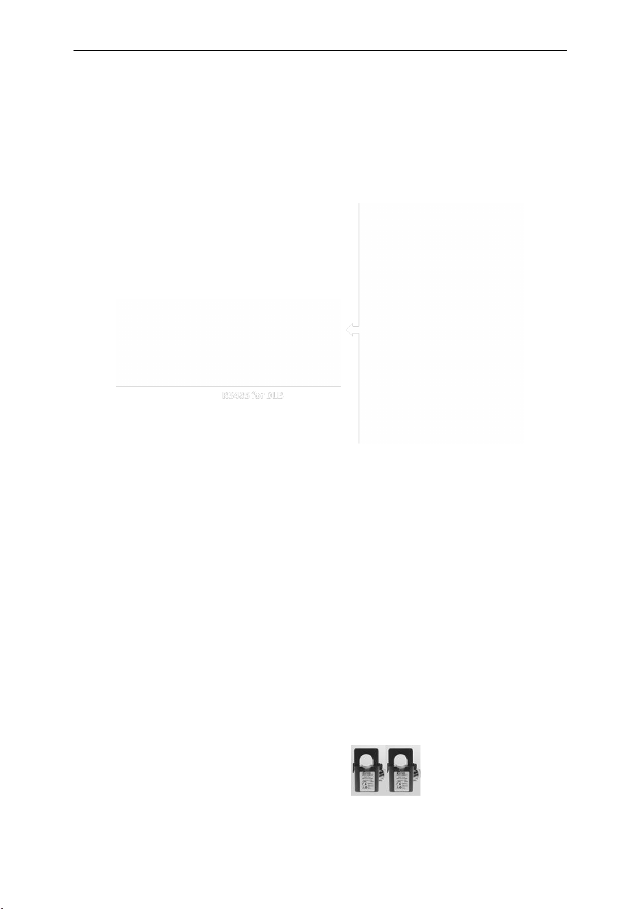
VISION is equipped with an RS485 communication interface that supports Dynamic Load Balancing
(DLB).
Fig. 9-1 RS485 for DLB
The DLB function can be implemented in the following ways:
Connecting an external smart meter: Enables PV-priority operation and household dynamic load
balancing when integrated with a photovoltaic system.
Connecting multiple chargers via an RS485 bus: Allows power sharing among charging stations.
Since the device has only one RS485 interface, only one DLB mode can be used at a time.
9.1.1. Solar charging + Dynamic load balance via smart meter
Energy Meter
Fig. 9-2 Energy Meter and CT
VISION Level 2 AC EV Charging station User Manual
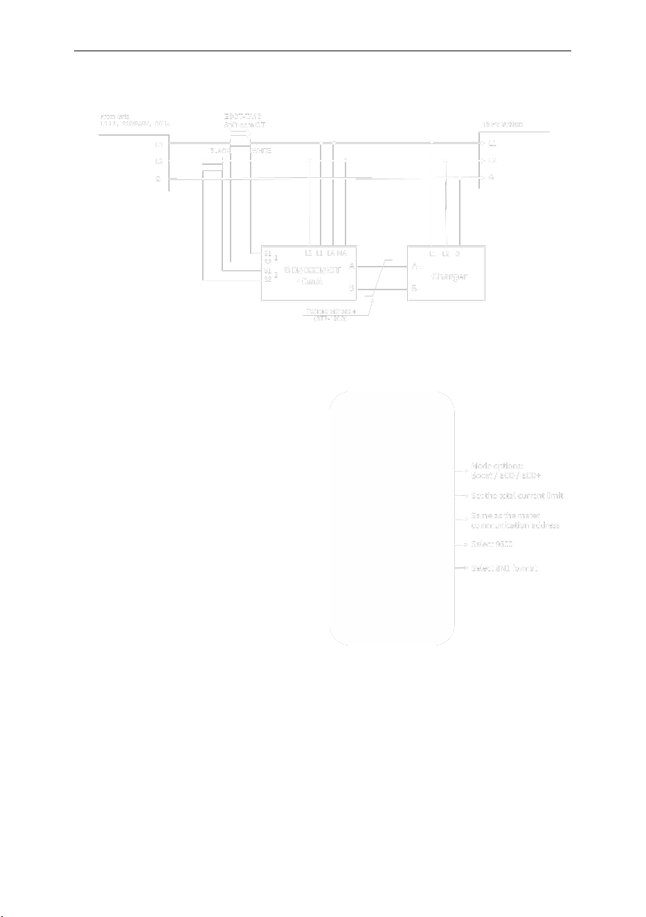
Wiring Methods:
Fig. 9-3 Wiring of meter
Operation
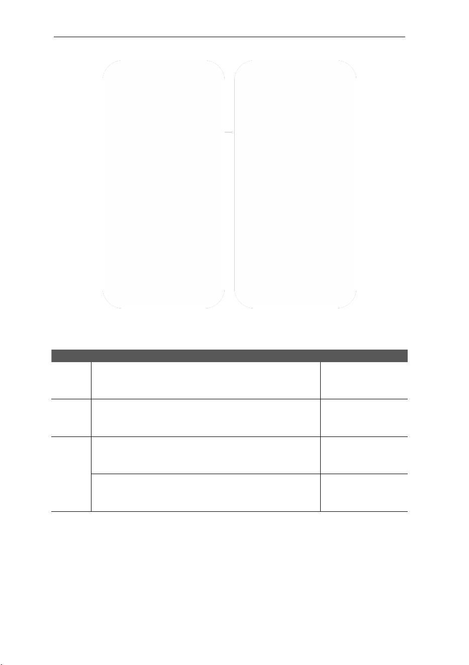
a) Set the Solar logic Charging
mode and DLB Current limit
Method:
users need to log in the
configuration page, select the DLB
setting interface, select “solar
logic & DLB” for the DLB mode,
how to log in to the configuration
page, please refer to chapter 6.6 of
this manual
set the relevant parameters by
demand.
Fig 9-4 Solar logic & DLB in configuration page
or use WE E-Charge APP setting the solar charging mode. Connect INJET ECO charging
station with the mobile phone through Bluetooth, and then scan the QR code on the
side of the charging station with WE E-Charge APP to binding; In the "Settings" menu of
WE E-Charge APP, you can set the parameters of solar charging
VISION Level 2 AC EV Charging station User Manual
Fig.9-5 Solar Logic and DLB Settings in the App
b) Charging mode of Solar logic
Mode
Description
Energy source
BOOST
Maximum charging power, the maximum charging current =
the set current of charging station, the charging current is
irrelevant to the output current of PV system.
Only Grid
Or only PV system
Or Grid + PV system
ECO+
Most economical charging, all charging energy comes from PV
system. And if the grid-connected current of PV system < 6A,
the charging will stop automatically.
Only PV system
ECO
If the grid-connected current of PV system ≥ 6A, the charging
current only comes from the PV system, and the charging
current = grid-connected current of PV system.
Only PV system
If the grid-connected current of PV system < 6A, the charging
current = 6A. The charging current which cannot be provided
by the PV system comes from the grid energy.
Grid + PV system
9.1.2. Dynamic load balance via Power Share
Feature Overview
A master charging station can be connected with up to nine slave charging stations via the RS485 bus.
The maximum shared current is set on the master station. Once any station starts charging, the master
VISION Level 2 AC EV Charging station User Manual
will dynamically allocate the charging current to ensure that the total current of all stations, including
itself, does not exceed the configured shared current limit.
RS485 Bus Wiring
Fi
g. 9-6 RS485 Wiring of power share
Operation
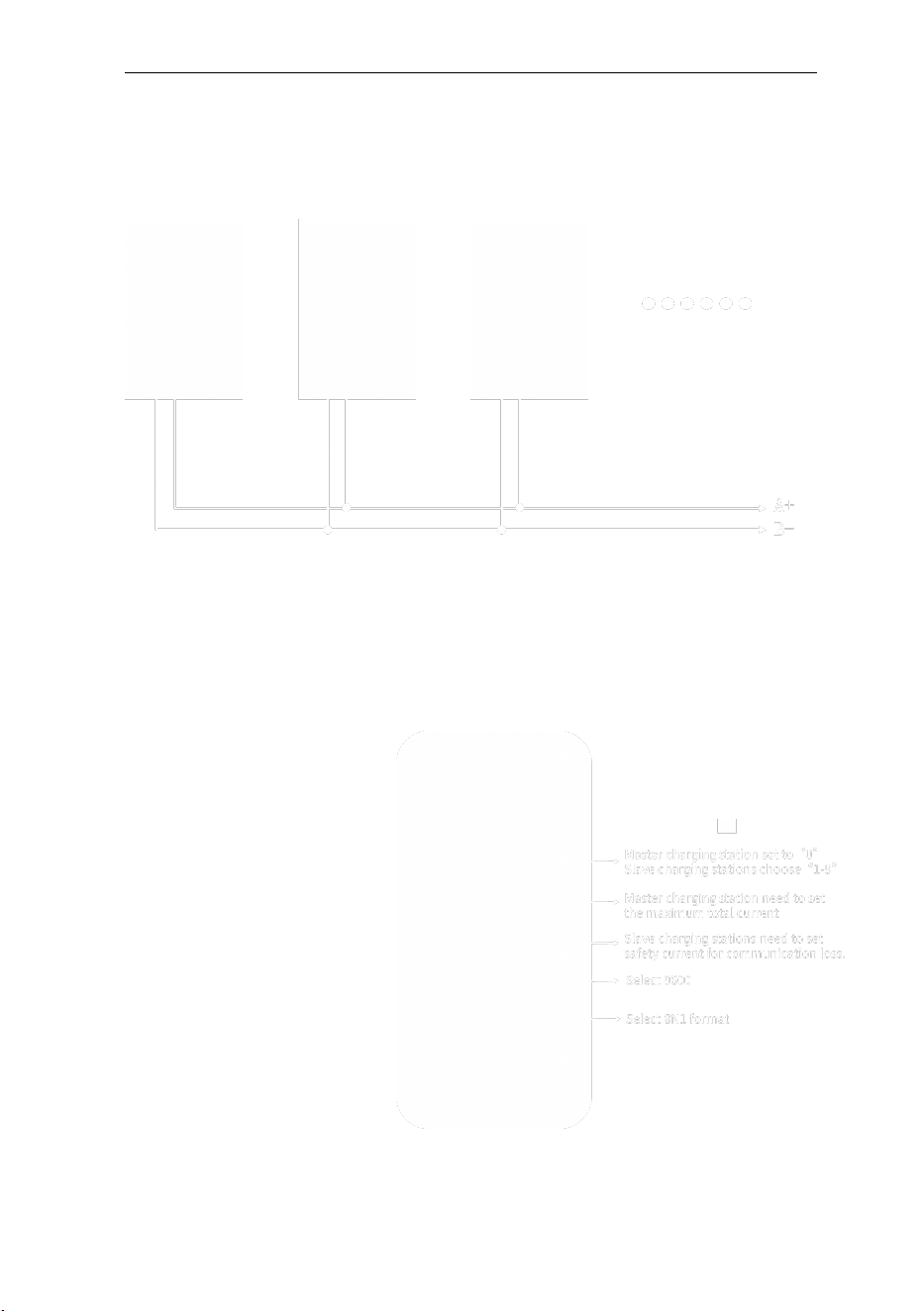
Users need to log in the configuration page, select the DLB setting interface, select “Power Share”
for the DLB mode.
The master charging station needs to
be set with ID “0” and then
configure the maximum current.
The slave charging stations need to
be set with IDs “1–9” and configure
the maximum safety current.
When communication is abnormal,
the charging station will operate
within the maximum safety current to
ensure that the total power remains
within the set range.
How to log in to the configuration
page, please refer to the chapter 6.6
of this user
manual.
Fig. 9-7 Power share setting in the configuration page

VISION Level 2 AC EV Charging station User Manual
WARRANTY AGREEMENT
1. The scope of warranty refers to the product itself.
2. The warranty period is 12 months. During the warranty period, the company will
repair the product free of charge in case of failure or damage (determined by the
company's technical personnel) under normal use.
3. The starting time of the warranty period is the date of product manufacture.
4. Even in the warranty period, a certain maintenance fee will be charged in case of the
following situations.
① Equipment failure caused by not following the user's manual.
② Equipment damage caused by fire, flood, abnormal voltage, etc.
③ Equipment damage caused by using the product for abnormal functions.
④ Equipment damage caused by foreign matter entering.
⑤ Equipment damage caused by other human external factors.
5. The service fee shall be calculated according to the actual cost. If there is another
contract, the contract shall prevail.
6. Please be sure to keep this card and show it to the maintenance personnel during the
warranty period.
7. If you have any questions, please contact the agent or our company directly.
After sales service center

For Both FCC & IC application:
This device complies with Part 15 of the FCC Rules / Industry Canada licence-exempt
RSS standard(s). Operation is subject to the following two conditions: (1) this device may not cause
harmful interference, and (2) this device must accept any interference received, including interference
that may cause undesired operation.
Le présent appareil est conforme aux CNR d'Industrie Canada applicables aux appareils radio exempts
de licence. L'exploitation est autorisée aux deux conditions suivantes: (1) l'appareil ne doit pas
produire de brouillage, et (2) l'utilisateur de l'appareil doit accepter tout brouillage radioélectrique
subi, même si le brouillage est susceptible d'en compromettre le fonctionnement.
Changes or modifications not expressly approved by the party responsible for compliance could void
the user's authority to operate the equipment.
This equipment has been tested and found to comply with the limits for a Class B digital device,
pursuant to part 15 of the FCC Rules. These limits are designed to provide reasonable protection
against harmful interference in a residential installation. This equipment generates uses and can
radiate radio frequency energy and, if not installed and used in accordance with the instructions, may
cause harmful interference to radio communications. However, there is no guarantee that interference
will not occur in a particular installation. If this equipment does cause harmful interference to radio or
television reception, which can be determined by turning the equipment off and on, the user is
encouraged to try to correct the interference by one or more of the following measures:
—Reorient or relocate the receiving antenna.
—Increase the separation between the equipment and receiver.
—Connect the equipment into an outlet on a circuit different from that to which the receiver is
connected.
—Consult the dealer or an experienced radio/TV technician for help.
MPE Requirements
To satisfy FCC / IC RF exposure requirements, a separation distance of 20 cm or more should be
maintained between the antenna of this device and persons during device operation.
To ensure compliance, operations at closer than this distance is not recommended.
Les antennes installées doivent être situées de facon à ce que la population ne puisse y être exposée à
une distance de moin de 20 cm. Installer les antennes de facon à ce que le personnel ne puisse
approcher à 20 cm ou moins de la position centrale de l’ antenne.
La FCC des éltats-unis stipule que cet appareil doit être en tout temps éloigné d’au moins 20 cm des
personnes pendant son functionnement.

We provide customers
with all-round technical support.
Any change or upgrade without prior notice!