

INJET HANHUI Series
DC Fast Charging Station
Installation and Operation Manual

Important Notices
Installation, operation, transport, handling, and maintenance of the equipment must be carried out in
accordance with this manual and all applicable laws, regulations, and standards. The manufacturer shall not
be liable for any damage or loss caused by improper operation or failure to comply with the requirements.
Failure to strictly follow the requirements of this manual will void the equipment warranty. Any operation
that deviates from this manual must obtain prior written approval from the manufacturer or an authorized
service partner.
Copyright Statement
© INJET New Energy 2026. All rights reserved. All copyrights, registered trademarks, and trademarks referenced
in this document belong to their respective owners.
The information in this document is subject to change without notice and shall not be interpreted as a commitment
by INJET New Energy or its affiliates. INJET New Energy assumes no responsibility for any errors that may
appear in this document.
This company reserves all rights to this document and to the topics, illustrations, technical data, and other contents
herein. Without the prior written permission of INJET New Energy, no part of this document may be reproduced,
disclosed to third parties, or used in whole or in part.
Manufacturer and Service
Manufacturer
INJET New Energy
Product Name
DC Fast Charging Station
Technical Support / After-Sales Service
Email:evse.support@injet.com
WhatsApp: +86-19181011063

Table of Contents
Important Notices .........................................................................................................................................................................................2
Copyright Statement ....................................................................................................................................................................................2
Manufacturer and Service ......................................................................................................................................................................... 2
1. Document Overview .............................................................................................................................................................................. 6
1.1 Purpose and Scope ......................................................................................................................................................................6
1.2 Product Model and Naming Rules........................................................................................................................................ 6
1.3 Terms, Abbreviations, and Referenced Standards........................................................................................................... 6
1.3.1 Abbreviations ............................................................................................................................................................................6
1.3.2 Terms ...........................................................................................................................................................................................7
1.3.3 Referenced Standards.............................................................................................................................................................7
2. Safety Instructions .................................................................................................................................................................................. 8
2.1 Warning Labels............................................................................................................................................................................8
2.2 Personnel Qualification Requirements ................................................................................................................................ 9
2.3 Equipment Use Restrictions .................................................................................................................................................... 9
2.4 Personal Protective Equipment............................................................................................................................................10
2.5 Scope of Responsibility and Disclaimer ...........................................................................................................................10
2.6 FCC and IC Remarks .............................................................................................................................................................. 11
3. Product Introduction ............................................................................................................................................................................13
3.1 Overall Appearance and Structure ......................................................................................................................................13
3.2 Main Components ....................................................................................................................................................................14
3.2.1 Core Components....................................................................................................................................................... 14
3.2.2 Human-Machine Interface....................................................................................................................................... 15
3.2.4 Options........................................................................................................................................................................... 15
4. Transport, Incoming Inspection, and Handling ..........................................................................................................................17

4.1 Packaging and Incoming Inspection ..........................................................................................................................17
4.2 Handling Requirements and Precautions ..........................................................................................................................17
4.2.1 Forklift Handling .........................................................................................................................................................18
4.2.2 Lifting Handling ..........................................................................................................................................................18
4.3 Unpacking and Packing List.................................................................................................................................................19
4.3.1 Unpacking Procedure................................................................................................................................................ 19
4.3.2 Packing List .................................................................................................................................................................. 19
5. Access to the Inside of Charger ....................................................................................................................................................... 21
5.1 Open/Close the Doors.............................................................................................................................................................21
5.1.1 Open/Close the Front Door ......................................................................................................................................21
5.1.2 Open/Close the Side Doors ......................................................................................................................................21
6. Pre-Installation Preparation ...............................................................................................................................................................23
6.1 Floor Space Requirements.................................................................................................................................................... 23
6.2 Foundation and Embedded Requirements ....................................................................................................................... 24
6.2.1 Prepare the Foundation............................................................................................................................................. 24
6.3 Cable Routing and Reserved Length................................................................................................................................. 24
6.4 Recommended Tools...............................................................................................................................................................26
7. Equipment Installation........................................................................................................................................................................27
7.1 Positioning and Fixing............................................................................................................................................................27
7.2 Post-Installation Inspection ...................................................................................................................................................27
8. Electrical Connection.......................................................................................................................................................................... 28
8.1 AC Input Connection.............................................................................................................................................................. 28
8.2 Communication Connection ................................................................................................................................................. 29
9. Commissioning and Initial Operation ............................................................................................................................................30
9.1 Power-On Steps........................................................................................................................................................................ 30
9.2 Basic Parameter Settings....................................................................................................................................................... 31
9.3 Charging Procedure ................................................................................................................................................................. 32
10. Maintenance and Troubleshooting............................................................................................................................................... 34

10.1 Routine Inspection and Maintenance Recommendations .........................................................................................34
10.1.1 External Inspection.................................................................................................................................................. 34
10.1.2 Internal Inspection ....................................................................................................................................................34
10.2 Common Fault Troubleshooting .......................................................................................................................................35
10.3 Safe Shutdown and Power-Off Procedure.....................................................................................................................36
11. Technical Data and Appendix ........................................................................................................................................................37
11.1 Technical Data Table............................................................................................................................................................37
11.2 Overall Dimensions ...............................................................................................................................................................39

1. Document Overview
This manual describes the installation and operating instructions for INJET HanHui DC EV charger. Before
installing this product, read this manual carefully and become familiar with all relevant requirements and
operating instructions to ensure that the equipment is installed and commissioned safely, correctly, and smoothly.
1.1 Purpose and Scope
This manual provides guidance for the transport, installation, electrical connection, commissioning, trial operation,
routine use, and basic maintenance of INJET HanHui.
· Field installers
· After-sales service engineers
· Operation and maintenance personnel
· Users
1.2 Product Model and Naming Rules
To facilitate product identification, configuration management, order confirmation, and after-sales service, this
product uses a unified model coding rule.
iHAP
-□□□□
□
□
Ad screen code:
X: No Ad screen
D: With Ad screen
Charger version
:
U: CSA version
E: CE version
Rated power code:
120A: 120kW, Air cooling
160A: 160kW, Air cooling
240A: 240kW, Air cooling
320A: 320kW, Air cooling
320L: 320kW, Liquid cooling
400L: 400kW, Liquid cooling
480L: 480kW, Liquid cooling
Product series code
This manual applies to the following HVIN / product models
iHAP-480LUD, iHAP-400LUD, iHAP-320LUD, iHAP-320AUD, iHAP-240AUD, iHAP-160AUD, iHAP-
120AUD, iHAP-480LUX, iHAP-400LUX, iHAP-320LUX, iHAP-320AUX, iHAP-240AUX, iHAP-160AUX,
iHAP-120AUX.
1.3 Terms, Abbreviations, and Referenced Standards
1.3.1 Abbreviations
Abbreviation
Description
AC
Alternating current
CCS
Combined Charging System, a standard charging method for electric
vehicles
DC
Direct current
EMC
Electromagnetic compatibility
EV
Electric vehicle
HMI
Human Machine Interface
MCB
Miniature circuit breaker
MID
Measuring Instruments Directive
NACS
North American Charging Standard
OCPP
Open charge point protocol
PE
Protective earth
PPE
Personal protective equipment
RFID
Radio-frequency identification
SPD
Surge protective devices
NOTE
It is possible that not all terms are present in this document.
1.3.2 Terms
Terminology
Description
Cabinet
Enclosure of the EVSE, including the components on the inside
Local rules
All rules that apply to the EVSE during the entire lifecycle of the
EVSE. The local rules also include the national laws and regulations
Open charge point protocol
Open standard for communication with charge stations
Protective devices
Devices for the personal protection of individuals against the risk of
injury or electrical shock when they do commissioning, operation and
maintenance activities. Examples of protective devices are a door, the
electrical parts covers, the latches, etc.
Site operator
Entity that is responsible for the day-to-day control of the EVSE. The
site operator does not have to be the owner
Qualified installer
The installer is a qualified person to install the EVSE according to the
applicable local rules and fully knows the EVSE and its safe
installation. The qualified installer obeys all local rules and the
instructions in the operation and installation manual.
Owner
Legal owner of the EVSE
User
Owner of an EV, who uses the EVSE to charge the EV
NOTE
It is possible that not all terms are present in this document.
1.3.3 Referenced Standards
System Certifications
ETL, FCC, CSA, Energy Star
Metering
CTEP/NTEP
EMC
FCC 47 CFR Part 15B (Class A)
OCPP
1.6J and 2.0.1
Vehicle Communication Protocol
DIN SPEC 70121, ISO 15118-2, ISO 15118-3, Plug &
Charge
2. Safety Instructions
This chapter summarizes the principal risk warnings, operational limitations, and safety requirements that must be
observed during transport, installation, commissioning, operation, and maintenance.
2.1 Warning Labels
This manual uses different signal words and safety symbols to indicate potential risks during unpacking, handling,
installation, commissioning, operation, and maintenance. Personnel must understand the meaning of all warning
information and strictly follow the relevant requirements.
Warning labels identify different types of hazards. The risk level shall be determined based on the equipment
location, job scenario, and possible consequences, and the corresponding management and protective measures
shall be taken according to DANGER, WARNING, CAUTION, or NOTE.
DANGER
Indicates an imminently hazardous situation. If not avoided, it will result in death
or serious injury.
WARNING
Indicates a potentially hazardous situation which, if not avoided, could result in
serious personal injury, death, or major equipment damage.
CAUTION
Indicates a low to medium level of risk. If not avoided, it may result in minor or
moderate injury, equipment damage, or abnormal operation.
NOTE
Indicates information not directly related to personal injury but very important for
correct installation, operation, and maintenance. Failure to follow it may lead to
equipment faults, performance degradation, data loss, or difficulty in subsequent
maintenance.
Hazardous voltage. Risk of electric shock.
Protective earth connection required.
Beware of pinch points.
General mandatory action sign.
Disconnect before carrying out maintenance or repair.
2.2 Personnel Qualification Requirements
· Unpacking, handling, installation, wiring, commissioning, maintenance, and servicing of the equipment
shall be carried out only by qualified professionals who have received appropriate product training.
· Unauthorized personnel shall not open the cabinet, remove protective parts, modify parameters, or
perform any repair work.
· Personnel shall be familiar with all applicable local electrical safety regulations, grounding
requirements, lockout/tagout (LOTO) procedures, and operating practices for high-voltage equipment.
· During cabinet opening, maintenance, and power-on testing, necessary isolation measures shall be
implemented to prevent unauthorized persons from entering the work area.
DANGER
When live inspection, energized commissioning, or internal maintenance is involved, the work
must be carried out by properly qualified professionals and strictly follow the procedures for
power isolation, lockout, verification of absence of voltage, and discharge.
WARNING
This equipment contains high-voltage electrical components and heavy structural parts.
Operation by unqualified personnel may result in electric shock, fire, equipment damage, or
personal injury.
2.3 Equipment Use Restrictions
· This equipment is intended for charging electric vehicles that comply with applicable standards, and is
suitable for indoor or outdoor locations that meet installation, grid, environmental, and safety requirements.
· Do not install or operate the equipment in flammable or explosive environments, areas with severe water
accumulation, corrosive environments, or any other unsafe conditions. Stop using the equipment
immediately if any damage, water ingress, abnormal odor, abnormal noise, overheating, or alarm occurs.
· Do not modify the equipment structure, software settings, electrical connections, or protection parameters
without the manufacturer
’
s written approval. Do not use unauthorized adapters, extension cords, or other
non-specified accessories.
CAUTION
If the equipment has abnormalities, damage, or safety risks, it must not continue to operate.

2.4 Personal Protective Equipment
Depending on the work being performed, personnel shall wear appropriate personal protective equipment (PPE),
including but not limited to:
Protective clothing
Safety gloves
Safety helmet
Safety goggles
Safety shoes
2.5 Scope of Responsibility and Disclaimer
This equipment shall be transported, installed, wired, commissioned, operated, maintained, and serviced only by
qualified personnel in accordance with this manual and all applicable local laws, regulations, standards, and codes.
Users, installers, service providers, and other relevant parties shall comply with the safety requirements, operating
limitations, PPE requirements, and cybersecurity and data protection requirements specified in this manual.
The manufacturer declares that this equipment complies with the applicable design and regulatory requirements
when it is properly transported, installed, used, and maintained. The manufacturer shall not be liable for any
personal injury, equipment damage, property loss, operational interruption, data loss, or any other related loss
resulting from failure to follow this manual, applicable regulations, or the manufacturer’s requirements.
The manufacturer shall not be liable for consequences caused by the following:
1. Improper installation, use, or maintenance
· Failure to follow this manual or applicable local laws, regulations, standards, and codes.
· Installation, wiring, commissioning, operation, or maintenance not performed as required.
· Power supply, grounding, installation environment, or operating conditions that do not meet equipment
requirements.
· Failure to carry out required inspection, testing, maintenance, or fault handling.
· Misuse, abuse, or use beyond the intended purpose.
2. Unauthorized modification or repair
· Disassembly, modification, repair, or system changes without the manufacturer’s written authorization.
· Unauthorized changes to product parameters, protection settings, communication settings, software
configuration, or control logic.
· Use of unapproved parts, accessories, tools, or third-party equipment in connection with this product.
3. Damage caused by external or uncontrollable factors

· Fire, flooding, storms, lightning, earthquakes, chemical leaks, pollution, or other force majeure events.
· Entry of foreign objects, corrosive substances, moisture, condensation, insects, rodents, or other external
factors into the equipment.
· External power supply abnormalities, grid fluctuations, upstream equipment failures, or third-party system
failures.
· Damage, performance degradation, or component failure caused by improper transportation, handling, or
storage.
4. Improper or unsafe operation
· Installation, wiring, commissioning, maintenance, or repair by unqualified personnel.
· Failure to wear required PPE or to take necessary safety precautions.
· Live working, improper operation, or forced energization/operation before faults are cleared.
· Continued use of the equipment under abnormal alarm, odor, overheating, smoke, or other abnormal
conditions.
5. Cybersecurity, data, or external system issues
· Failure to properly configure user permissions, network connections, passwords, or access control measures.
· Data leakage, communication failures, or system intrusion caused by improper management by the user,
operator, or third parties.
· Functional limitations or service interruption caused by failures of the backend platform, network operator,
payment platform, or other external systems.
6. Improper disposal
· Failure to dispose of the equipment, batteries, electronic components, or packaging materials in accordance
with applicable laws, regulations, and environmental requirements.
· Losses or liabilities arising from improper scrapping, recycling, dismantling, or transfer.
2.6 FCC and IC Remarks
FCC Caution:
Any Changes or modifications not expressly approved by the party responsible for compliance could void the
user's authority to operate the equipment.
This device complies with part 15 of the FCC Rules. Operation is subject to the following two conditions: (1) This
device may not cause harmful interference, and (2) this device must accept any interference received, including
interference that may cause undesired operation.
IMPORTANT NOTE:
Note: This equipment has been tested and found to comply with the limits for a Class A digital
device, pursuant to part 15 of the FCC Rules. These limits are designed to provide reasonable
protection against harmful interference when the equipment is operated in a commercial
environment. This equipment generates, uses, and can radiate radio frequency energy and, if not
installed and used in accordance with the instruction manual, may cause harmful interference to
radio communications. Operation of this equipment in a residential area is likely to cause harmful
interference in which case the user will be required to correct the interference at his own expense.

IC Caution::
This device complies with Innovation, Science, and Economic Development Canad licence-exempt RSS
standard(s).Operation is subject to the following two conditions:
(1) this device may not cause interference, and
(2) this device must accept any interference, including interference that may cause undesired operation of the
device.
Le présent appareil est conforme aux CNR d' Innovation, Sciences et Développement économique Canada
applicables aux appareils radio exempts de licence. L'exploitation est autorisée aux deux conditions suivantes:
(1) l'appareil nedoit pas produire de brouillage, et
(2) l'utilisateur de l'appareil doit accepter tout brouillage radioélectrique subi, même si le brouillage est susceptible
d'en compromettre le fonctionnement.
FCC/IC Radiation Exposure Statement:
This equipment complies with FCC/ISED radiation exposure limits set forth for an uncontrolled
environment. This equipment should be installed and operated with minimum distance 20cm between the
radiator& your body.
L'appareil est conforme aux limites d'exposition aux rayonnements spécifiées par la FCC/ISED pour les
environnements non contrôlés. La distance entre le radiateur et le corps doit être d'au moins 20 cm lors de
l'installation et du fonctionnement de l'appareil.
3. Product Introduction
This chapter introduces the overall structure, external appearance, and main functions of the equipment to help
users quickly understand the product’s basic configuration, operating interface, and the purpose of its key
components.
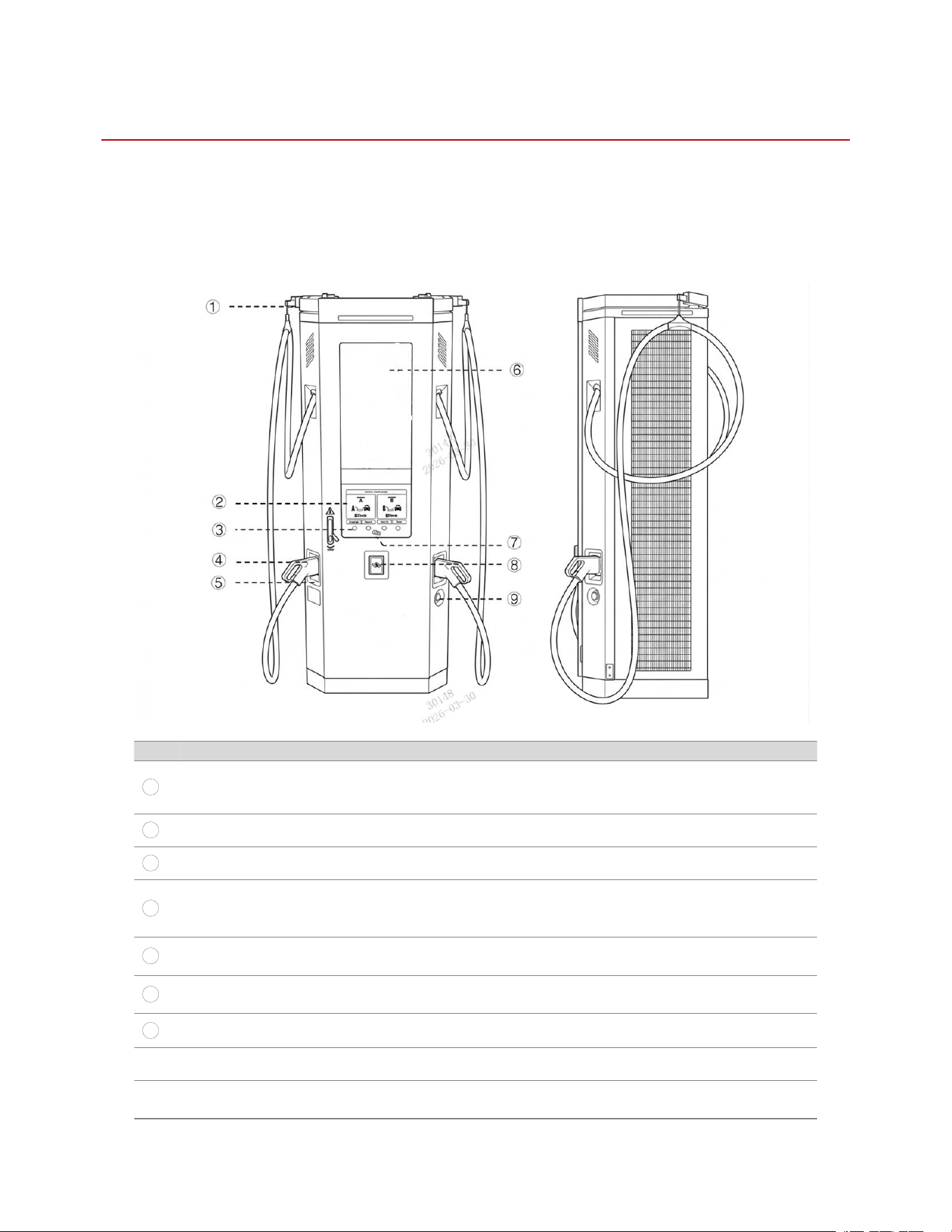
3.1 Overall Appearance and Structure
Ref.
Part
Function
1
Cable management system
To support and manage the charging connector and cable,
helping reduce cable dragging and wear during operation.
2
Display
Human-machine Interface (HMI)
3
Display’s buttons
To interact with the display menu
4
Charging connector-Output A
To connect the Output A of the EVSE to the
EV;Optional: NACS Charging Gun or CCS1 Charging
Gun
5
Connector holder with LED-
Output A
To hold the charging connector and show the status of
Output A
6
Ad screen(optional)
To support high-definition video and image
advertisements
7
RFID
To read the information from an RFID card
⑧
Payment terminal(optional)
To pay for the charging session
⑨
Emergency stop button (optional)
To manually stop the charging process instantly if any
danger is detected.
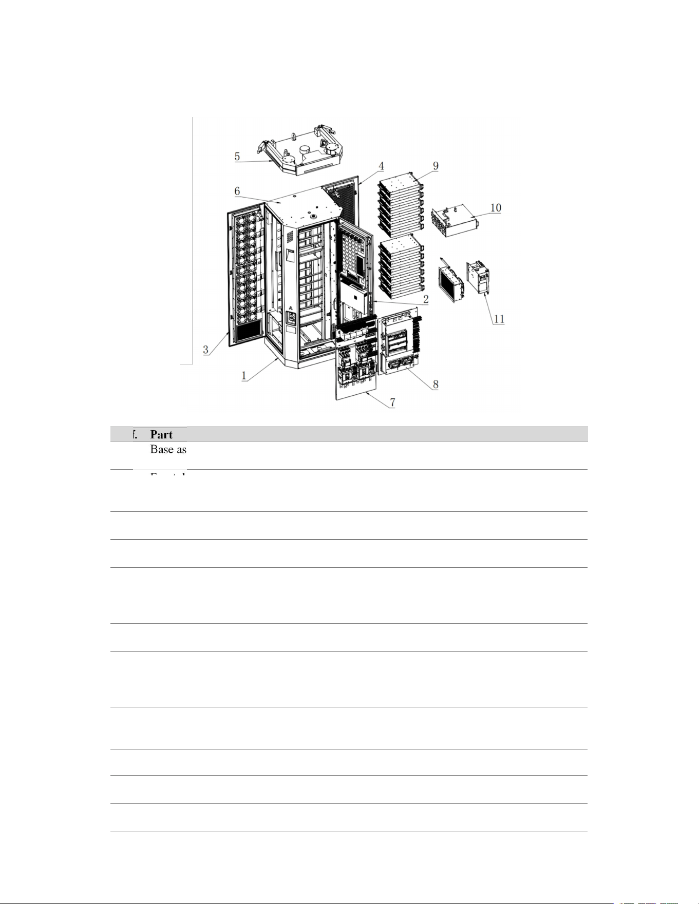
3.2 Main Components
3.2.1 Core Components
Ref.
Part
Description
1
Base assembly
An auxiliary support assembly used to connect the
charger cabinet body to the installation foundation
2
Front door assembly
Includes the human-machine interaction module,
advertising display, advertising screen control board,
door lock, etc.
3
Left door Assembly
Includes cooling fan 5, waterproof layer, etc.; used for
air exhaust
4
Right door Assembly
Includes dust filter cotton, waterproof layer, etc., used
for air intake
5
Cable and connector
management assembly
Includes the lifting rings, cable management system,
and connector-related components; used for equipment
lifting, cable support, and connector management
during charging operation.
6
Frame assembly
The main cabinet structure of the charger
7
AC component assembly
Includes the AC incoming terminal block, molded case
circuit breaker (MCCB), surge protective device (SPD),
etc.; mainly used for protection and power supply of the
incoming circuit
8
DC control assembly
Includes the energy meter, power controller, and other
DC-side control components; used for system control,
power regulation, and operating status monitoring.
9
Power module
The AC DC module array cabinet of the charger
10
Dispatch assembly
The five-section busbar distribution assembly on the
DC side
11
Liquid cooling assembly
Includes the cooling unit and pump body for heat
dissipation of the liquid-cooled charging cable.
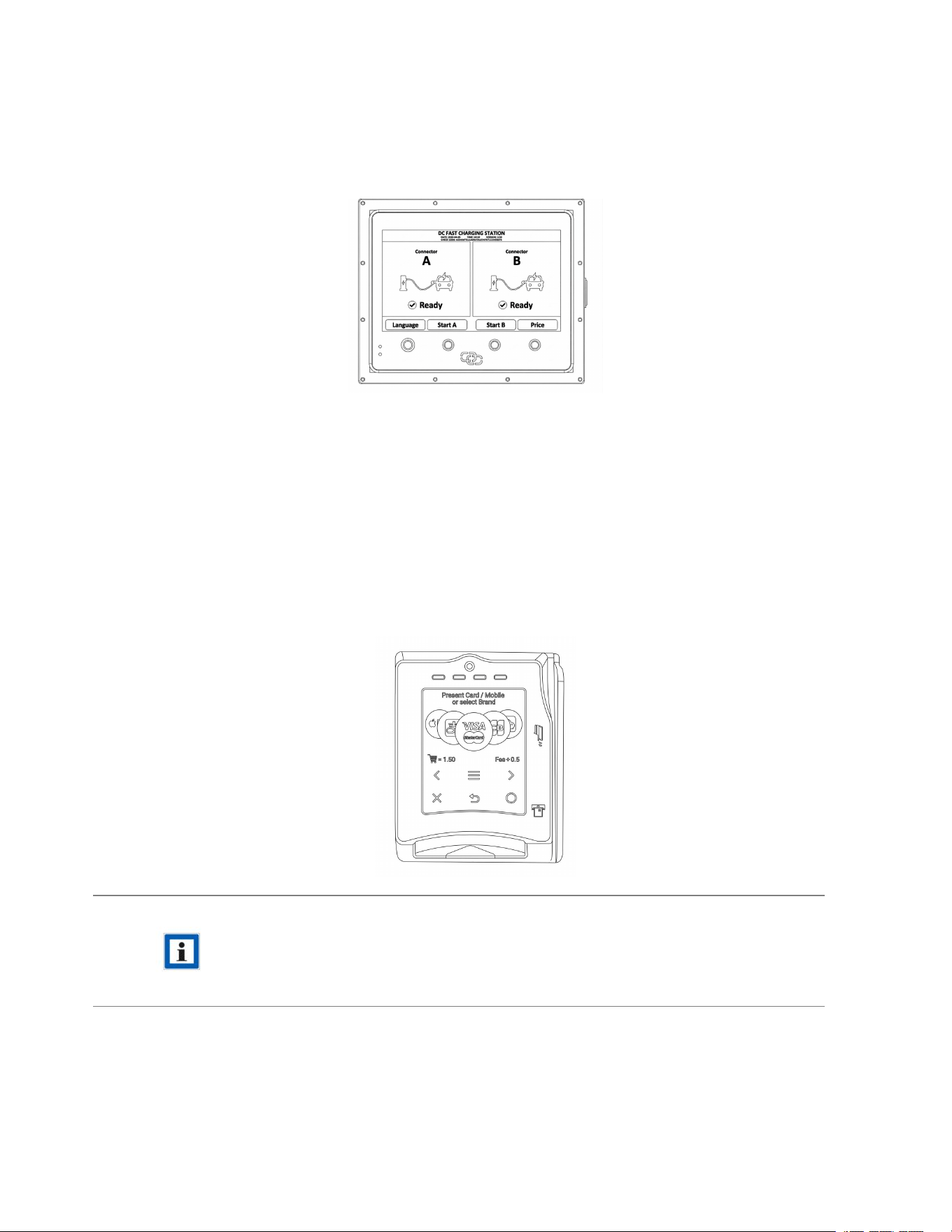
3.2.2 Human-Machine Interface
The HMI of this equipment provides both Day Mode and Night Mode. In both modes, the functional layout,
displayed information, and operating logic remain the same. The only differences are background color, font color,
and UI color scheme, to suit viewing and operation under different ambient light conditions.
3.2.4 Options
The equipment can be configured with different optional functions and expansion components according to
project requirements to meet the needs of different application scenarios related to use, payment, communication,
or operation management. Optional items are not part of the standard configuration. The actual scope of supply
shall be subject to the order, technical agreement, or product configuration list.
1. Payment Terminal
A payment terminal can be integrated to support user payment during charging. The payment terminal interfaces
with the OCPP platform via a cloud-to-cloud method to achieve payment authorization, transaction processing,
and status synchronization.
NOTE
To ensure payment security, the equipment owner or site operator should periodically inspect
the payment terminal to confirm that its appearance is intact, it is securely fixed, labels are
normal, and there are no abnormal openings, exposed cables, suspicious add-ons, or any signs of
removal or tampering. If any abnormality is found, stop using the payment terminal immediately
and contact service personnel for inspection and handling.
2. Ad Screen
The equipment can integrate a 32-inch ad screen for displaying images, videos, and other visual information. The
ad screen can serve as an extended display module for information release, advertising display, or interface
content presentation. It operates independently from the charging system and does not participate in charging
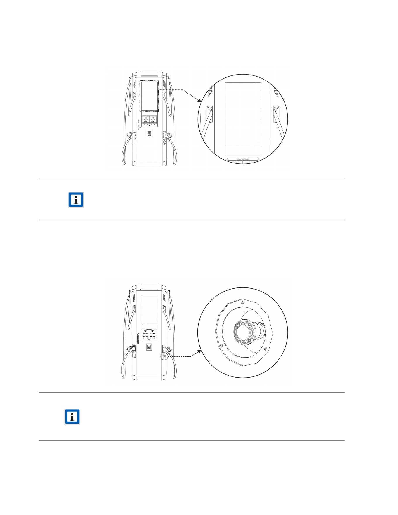
control or payment control. Display content, playback mode, and update method are subject to the actual
configuration.
NOTE
To ensure normal use, regularly inspect the appearance and installation status of the ad screen to
confirm that the screen surface is intact, the display is normal, and the unit is securely fixed
without damage, looseness, or other abnormal conditions. If abnormal display behavior or
hardware damage is found, stop using the display function and contact service personnel for
inspection and handling.
3. Emergency Stop Button
A Start/Stop button is provided as standard. An emergency stop button is optional and can be configured
according to customer requirements. It is mainly used to stop the equipment immediately in case of emergency,
abnormal operation, or safety risk.
NOTE
·
If the emergency stop button is pressed during charging, the AC contactor on the input side
and the DC contactor on the output side will be disconnected, and the status indicator will
turn red.
· After the fault has been cleared, ensure that it is safe to resume operation, then rotate the
emergency stop button clockwise to release it. The charger will then return to normal
operation.
4. Transport, Incoming Inspection, and Handling
This chapter describes the requirements from delivery and unpacking inspection to handling before equipment
positioning. To avoid damage during transport, loading/unloading, and handling, complete the package inspection,
incoming inspection, accessory verification, and handling confirmation in accordance with this chapter. If
abnormalities are found, record and handle them promptly, and proceed to the next installation step only after
confirmation.
4.1 Packaging and Incoming Inspection
· Check whether the package is damaged, punctured, cracked, deformed, damp, contaminated, or shows signs
of tipping.
· Verify that shipping marks, model labels, quantity labels, and project identification marks are clear.
· Verify that the model, quantity, and related information match the purchase order, shipping list, or packing
list.
WARNING
·
If the outer packaging is severely damaged, obviously wet, or shows signs of heavy
impact, do not unpack, install, or energize the equipment until its condition has been
confirmed.
· If the delivery information does not match the order or shipping documents, suspend
subsequent work and verify it in time.
4.2 Handling Requirements and Precautions
NOTE
· Before handling, confirm the equipment weight, center of gravity, and site access
conditions.
· For outdoor handling, take rainproof and moisture-proof measures.
WARNING
·
During lifting, personnel must not stay beneath the equipment or within the danger zone.
· During forklift handling, personnel must stay clear of the equipment tip-over risk area.
Wear the personal protective equipment required for the working area.
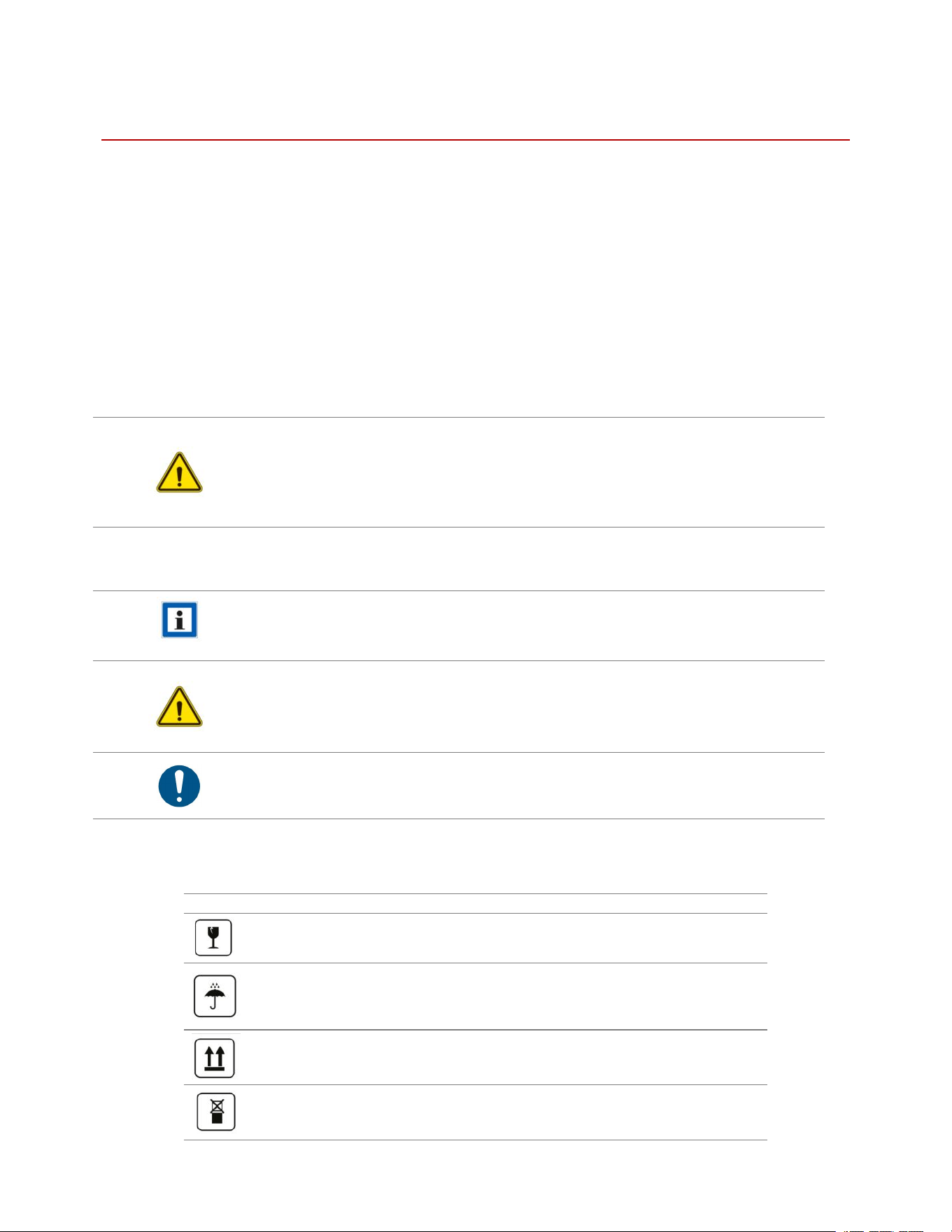
During handling, strictly follow the symbols shown on the packaging crate:
Symbol
Description
Fragile
Keep dry
This side up
Do not stack
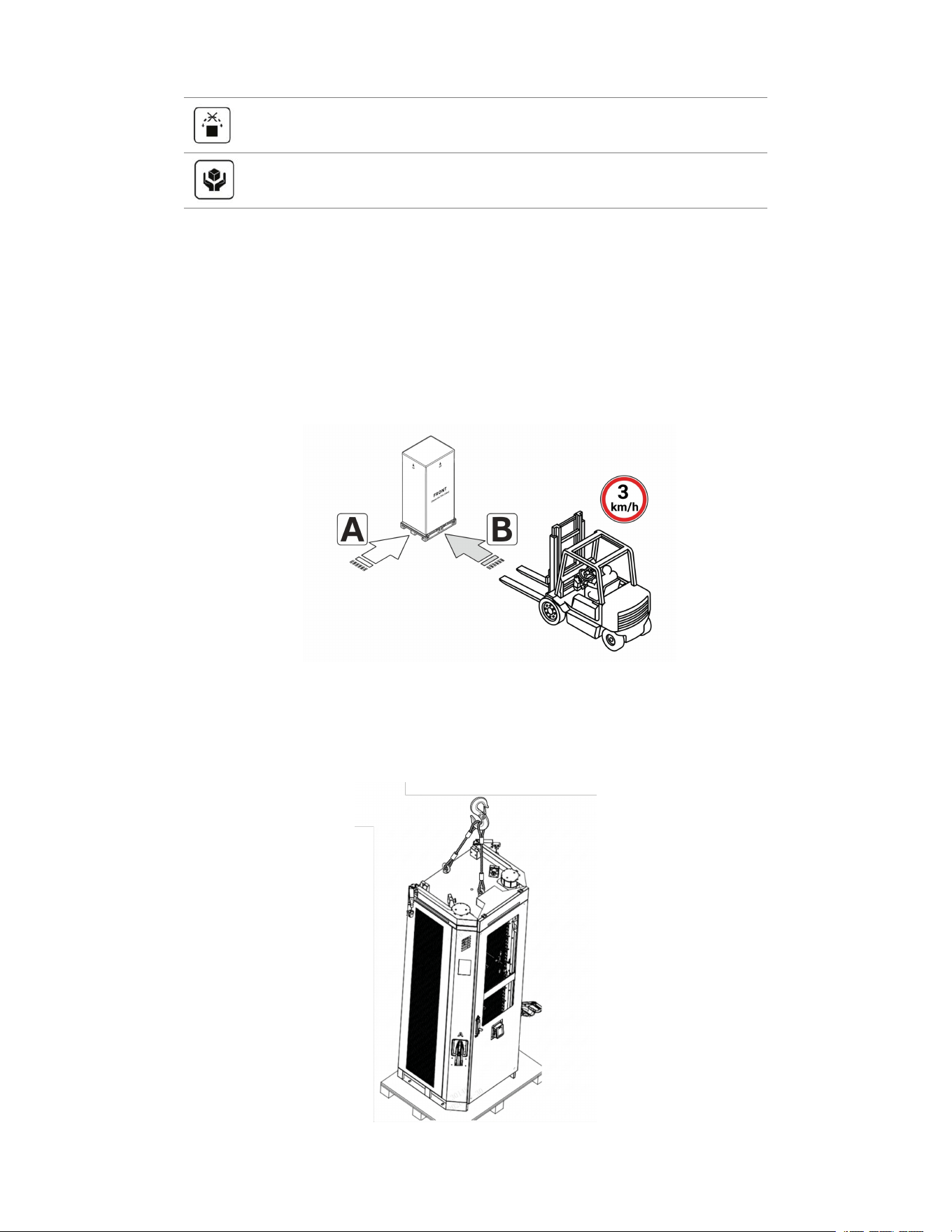
Do not tilt
Handle with care
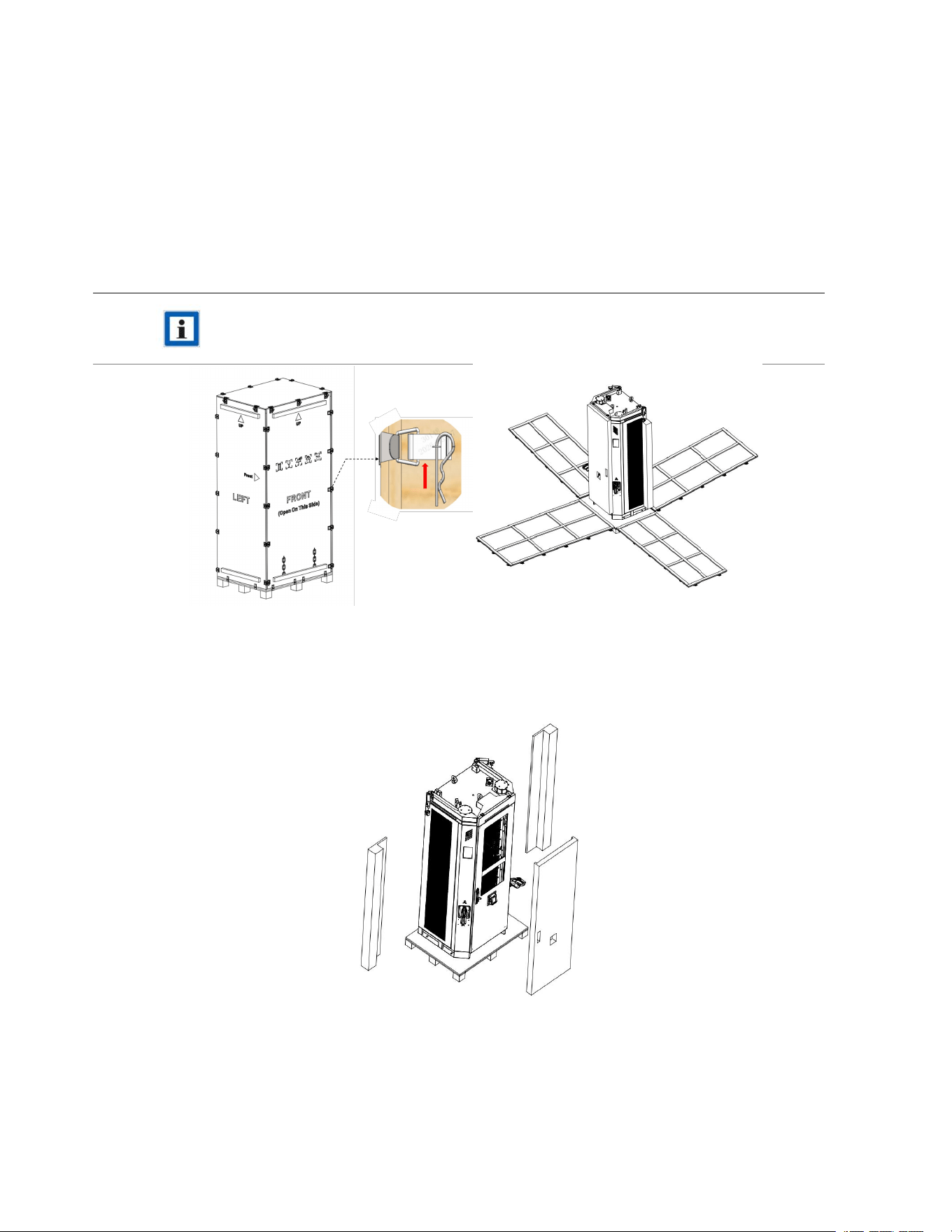
4.2.1 Forklift Handling
· Before handling, verify that the forklift capacity, fork dimensions, and fork entry positions meet the
requirements.
· During handling, ensure that the equipment remains stable and that there is no risk of tilting, collision, or
dropping.
· After handling, inspect the external appearance and visible parts of the equipment. Proceed with installation
only after confirming that no abnormality is found.
As shown in the figure, the forklift must pick up the charger from the front side(B) of the wooden crate.
4.2.2 Lifting Handling
When lifting is used, compliant lifting tools, slings, or hooks shall be used. Confirm that the lifting points are
reliable, the connections are secure, and the load is balanced. Keep the equipment stable during lifting and
positioning. Rapid lifting/lowering, swinging, collision, or diagonal pulling is strictly prohibited.
4.3 Unpacking and Packing List
4.3.1 Unpacking Procedure
Please unpack the equipment in accordance with the following steps, and take care to protect the appearance of
the equipment and its accessories during the unpacking process.
Step 1: Open the crate side panels
Release the latches to open the cabinet from each side.
NOTE
The door lock uses a removable pin and can be opened without tools.
Step 2: Remove all protective materials
Remove all foam protectors and other packaging materials from the equipment surface.
4.3.2 Packing List
After unpacking, check the charging cables, keys, certificate of conformity, installation accessories, manual,
and other supplied items against the packing list, and retain the packaging materials for traceability in case
of any abnormality.

Component
Description
Quantity
User Manual
1
Factory Inspection Report
1
Packing List
1
Key
To open the front door of EVSE
2
RFID card
To run the charger under local mode
2
Packaging Bag
1
Fireproof putty
1
Keys
2
Desiccant
60G
4
5. Access to the Inside of Charger
5.1 Open/Close the Doors
HAZARDOUS VOLTAGE
Make sure that only qualified persons have access to the door key and is wearing the correct
protective clothing as set out above.
Note
For ease of use, the key is usually fixed to the charging cable with a cable tie.
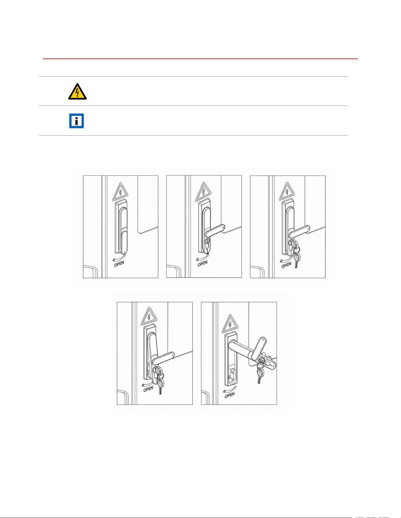
5.1.1 Open/Close the Front Door
Follow the steps shown in the figure to open the front door.
To close the side door, simply reverse the operation.
5.1.2 Open/Close the Side Doors
As shown in the figure, lift the latch at this position upward to open the right-side door. Use the same method to
open the left-side door.
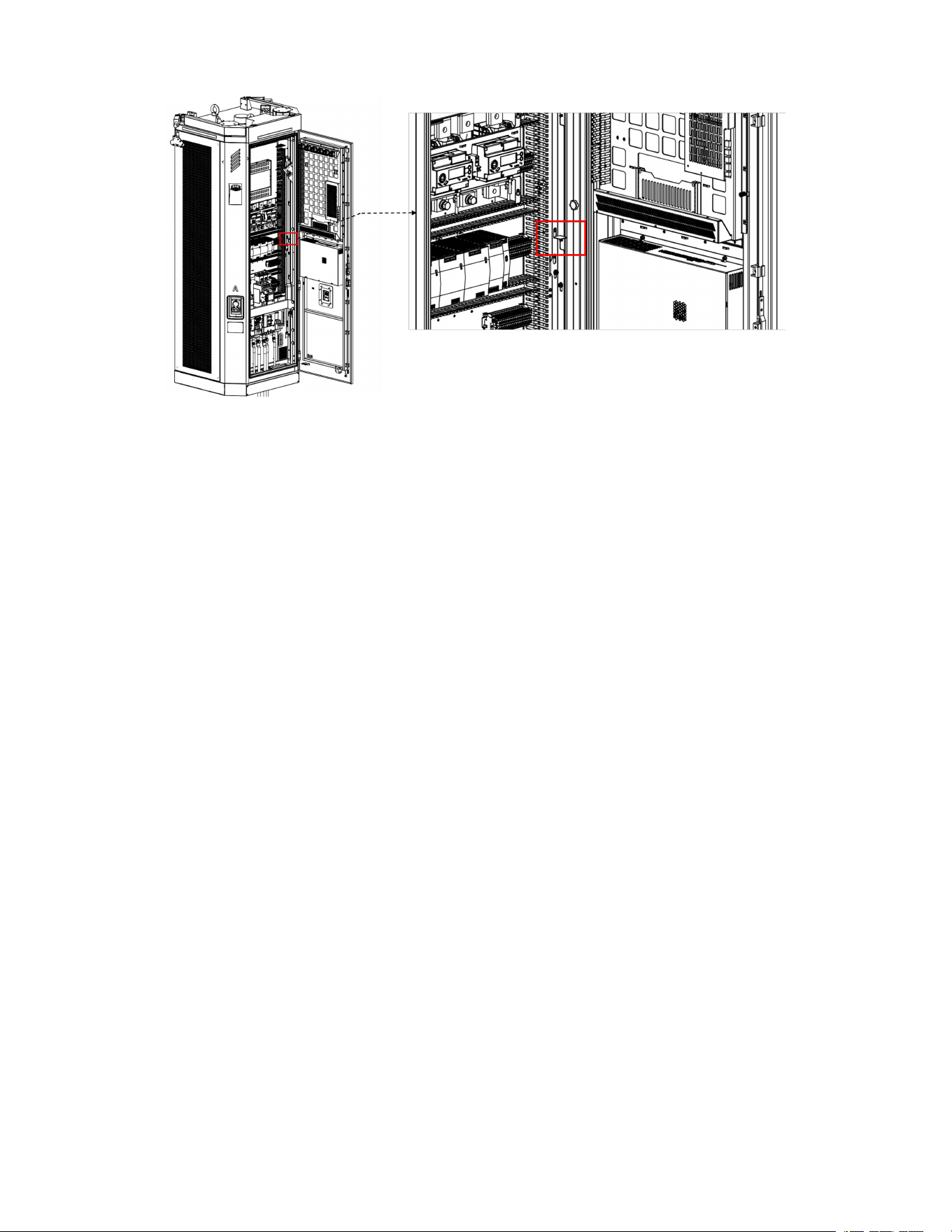
To close the side door, simply reverse the operation.
6. Pre-Installation Preparation
This chapter is used to confirm whether the installation site has the conditions required for construction and
equipment operation. Before formal installation, inspect the site environment, foundation and embedded parts,
cable routing, and reserved conditions so that installation, wiring, and subsequent commissioning can proceed
smoothly.
6.1 Floor Space Requirements
WARNING
- Do not install the equipment in a location with poor ventilation, insufficient space, or inadequate
maintenance clearance.
- Do not stack flammable materials, miscellaneous items, or any objects that obstruct heat dissipation or
maintenance around the equipment.
CAUTION
- During installation, ensure there are no obstacles around the equipment that affect normal door opening.
- Do not block the air inlet, air outlet, or maintenance working area.
- If multiple units are installed side by side, the minimum clearance requirements between adjacent units
must also be met.
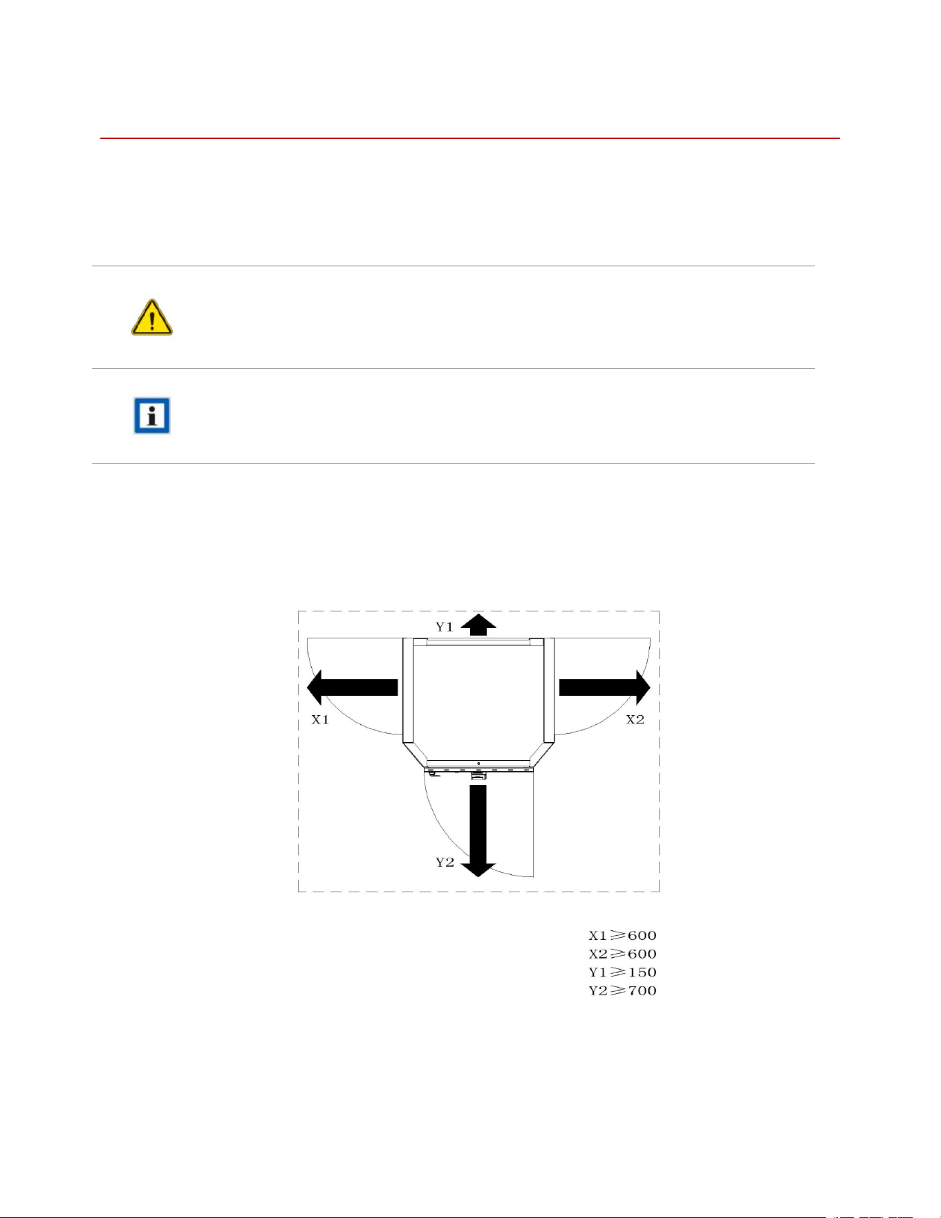
Before installation, confirm that sufficient space is reserved on site for handling, installation, door opening, wiring,
and heat dissipation. See the figure below for the minimum space requirements.
6.2 Foundation and Embedded Requirements
6.2.1 Prepare the Foundation
CAUTION
- After concrete pouring is completed, allow sufficient curing and reach the required installation strength
before drilling, installing expansion anchors, or fixing the equipment.
- It is recommended that power cables and signal cables be routed through separate embedded conduits.
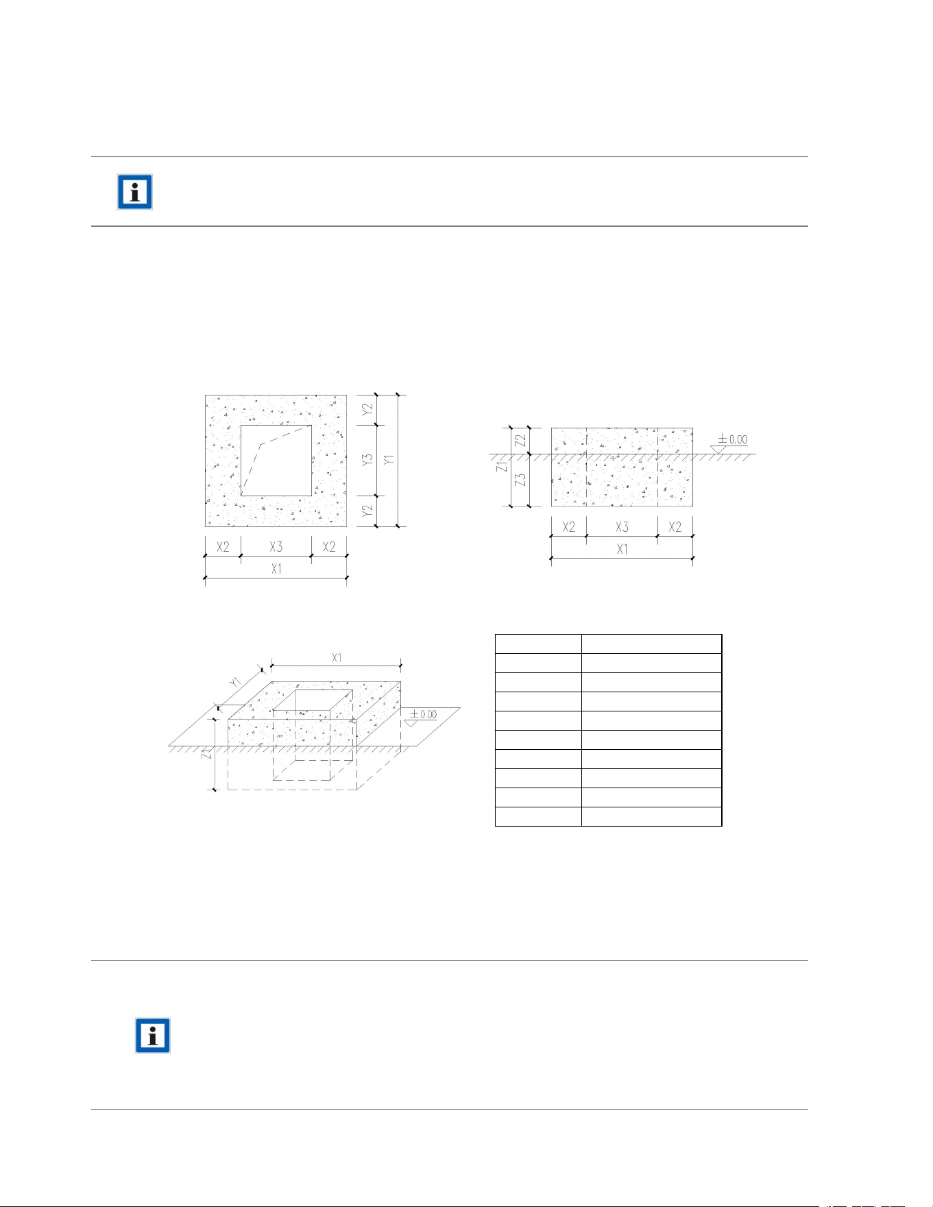
A concrete foundation meeting the load-bearing requirements shall be provided at the equipment installation
location. The length, width, and height of the concrete foundation shown in the figure below are recommended
values for reference in on-site foundation construction.
6.3 Cable Routing and Reserved Length
The maximum input current and recommended input cable size for different equipment power ratings are shown
in the table below.
NOTE
- Cable size standard: The recommended cable cross-sectional areas (mm²) are the minimum
requirements for safe operation. If any of the following conditions apply at the installation site, the
cable size shall be increased accordingly to ensure system stability:
·
The total cable routing length exceeds 200 m, with voltage drop taken into account.
· Heat dissipation conditions are poor, such as in crowded cable trays, enclosed conduits, or
high-temperature environments.
- The incoming cable can be either copper or aluminum. Please select one option only.
No.
Dimensions (mm)
X1
1080
X2
270
X3
540
Y1
1000
Y2
230
Y3
540
Z1
600
Z2
200
Z3
400

Model
Power
Cable Size
Terminal
iHAP-120AUD /
iHAP-120AUX
120 kW
(upgradable to 160 kW)
Copper cable: (3×95+1×50)×1
Aluminum cable: (3×120+1×70)×1
Copper cable:
(SC/DT 95-8)×3 + (SC/DT 50-8)×1 /
Aluminum cable:
(SC/DT 120-8)×3 + (SC/DT 70-8)×1
iHAP-160AUD /
iHAP-160AUX
160 kW
Copper cable: (3×95+1×50)×1 /
Aluminum cable: (3×120+1×70)×1
Copper cable:
(SC/DT 95-8)×3 + (SC/DT 50-8)×1 /
Aluminum cable:
(SC/DT 120-8)×3 + (SC/DT 70-8)×1
iHAP-240AUD /
iHAP-240AUX
240 kW
(upgradable to 320 kW)
Copper cable: (3×95+1×50)×1
Aluminum cable: (3×120+1×70)×1
Copper cable:
(SC/DT 95-8)×3 + (SC/DT 50-8)×1 /
Aluminum cable:
(SC/DT 120-8)×3 + (SC/DT 70-8)×1
iHAP-320AUD /
iHAP-320AUX
320 kW
Copper cable: (3×95+1×50)×1
Aluminum cable: (3×120+1×70)×1
Copper cable:
(SC/DT 95-8)×3 + (SC/DT 50-8)×1
Aluminum cable:
(SC/DT 120-8)×3 + (SC/DT 70-8)×1
iHAP-320LUD /
iHAP-320LUX
320 kW
(upgradable to 480 kW)
Copper cable: (3×150+1×95)×1
Aluminum cable: (3×240+1×120)×1
Copper cable:
(SC/DT 150-10)×3 + (SC/DT 95-
10)×1
Aluminum cable:
(SC/DT 240-10)×3 + (SC/DT 120-
8)×1
iHAP-400LUD /
iHAP-400LUX
400 kW
(upgradable to 480 kW)
Copper cable: (3×150+1×95)×1
Aluminum cable: (3×240+1×120)×1
Copper cable:
(SC/DT 150-10)×3 + (SC/DT 95-
10)×1
Aluminum cable:
(SC/DT 240-10)×3 + (SC/DT 120-
8)×1
iHAP-480LUD /
iHAP-480LUX
480 kW
Copper cable: (3×150+1×95)×1
Aluminum cable: (3×240+1×120)×1
Copper cable:
(SC/DT 150-10)×3 + (SC/DT 95-
10)×1
Aluminum cable:
(SC/DT 240-10)×3 + (SC/DT 120-
8)×1
The cables shall be routed through the concrete foundation and extend out from the top of the foundation, as
shown in the figure below. Make sure the cables are neatly arranged for subsequent installation and wiring.
6.4 Recommended Tools
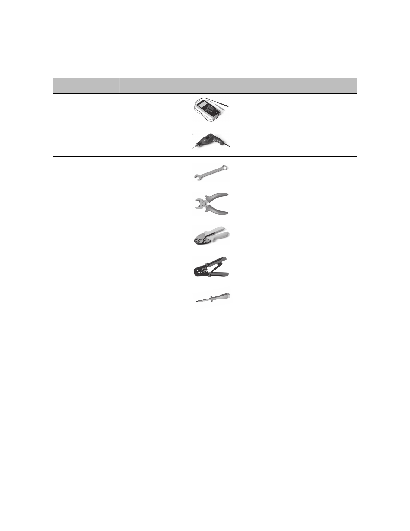
Before installing this equipment, it is recommended to prepare the following tools for electrical wiring and
electrical testing.
No.
Tools
Schematic Picture
Main Uses
1
Multimeter
Check the electrical connection
and measure the voltage
2
Electric Impact drill
Drill fixing holes in the wall
3
Wrench
Fastening bolt
4
Diagonal plier
Cut the cable
5
Wire stripper
Peeling cables
6
Crimping plier
Pressed cable terminal
7
Cross screwdriver
Fastening screw
7. Equipment Installation
This chapter describes the requirements for equipment positioning, fixing, and post-installation inspection.
7.1 Positioning and Fixing
There is a risk of pinching and crushing during lowering and positioning of the equipment.
CAUTION
- Before lifting the equipment, confirm that all cabinet doors are closed and locked.
- Check that all cables are free from kinks, twisting, crushing, or excessive bending.
- Lower and position the equipment slowly and steadily to avoid swinging, collision, or sudden
dropping.
Ensure that cables are not trapped between the equipment and the base, and that they are aligned correctly with
the AC and PE terminals.
7.2 Post-Installation Inspection
After the equipment has been lifted or moved to the foundation position, correct its orientation and levelness, and
tighten the anchor bolts or fasteners as required.
Inspection Item
Inspection Details
Fixing condition
Base bolts, anchor bolts, and installation fasteners are secured in
place; the equipment has no looseness or shaking.
Level condition
The equipment is installed steadily without obvious inclination.
Cable routing
Power cables, PE cables, communication cables, and other
cables are neatly routed without crushing, twisting, excessive
bending, or squeezing.
Marking inspection
Cable labels, phase sequence labels, and function labels are clear
and complete.
8. Electrical Connection
This chapter is a key part of on-site construction. Electrical connection work shall be carried out by qualified
professionals in combination with the actual electrical schematic, wiring diagram, terminal definitions, and torque
requirements.
WARNING
- Before electrical connection work, confirm that the upstream power supply has been disconnected
and necessary measures have been taken to prevent inadvertent energization.
- Live wiring, wire removal, or terminal tightening is strictly prohibited.
CAUTION
- Before electrical connection, verify that the equipment nameplate parameters match the on-site power
conditions.
- Terminal tightening shall meet the specified torque requirements and must not be excessively tight or
loose.
NOTE
- Before formal wiring, it is recommended to re-check cable specification, wire order, phase sequence,
and terminal definitions.
- For important wiring points, it is recommended to perform a secondary inspection and retain
necessary test records.
Protective earth connection required.
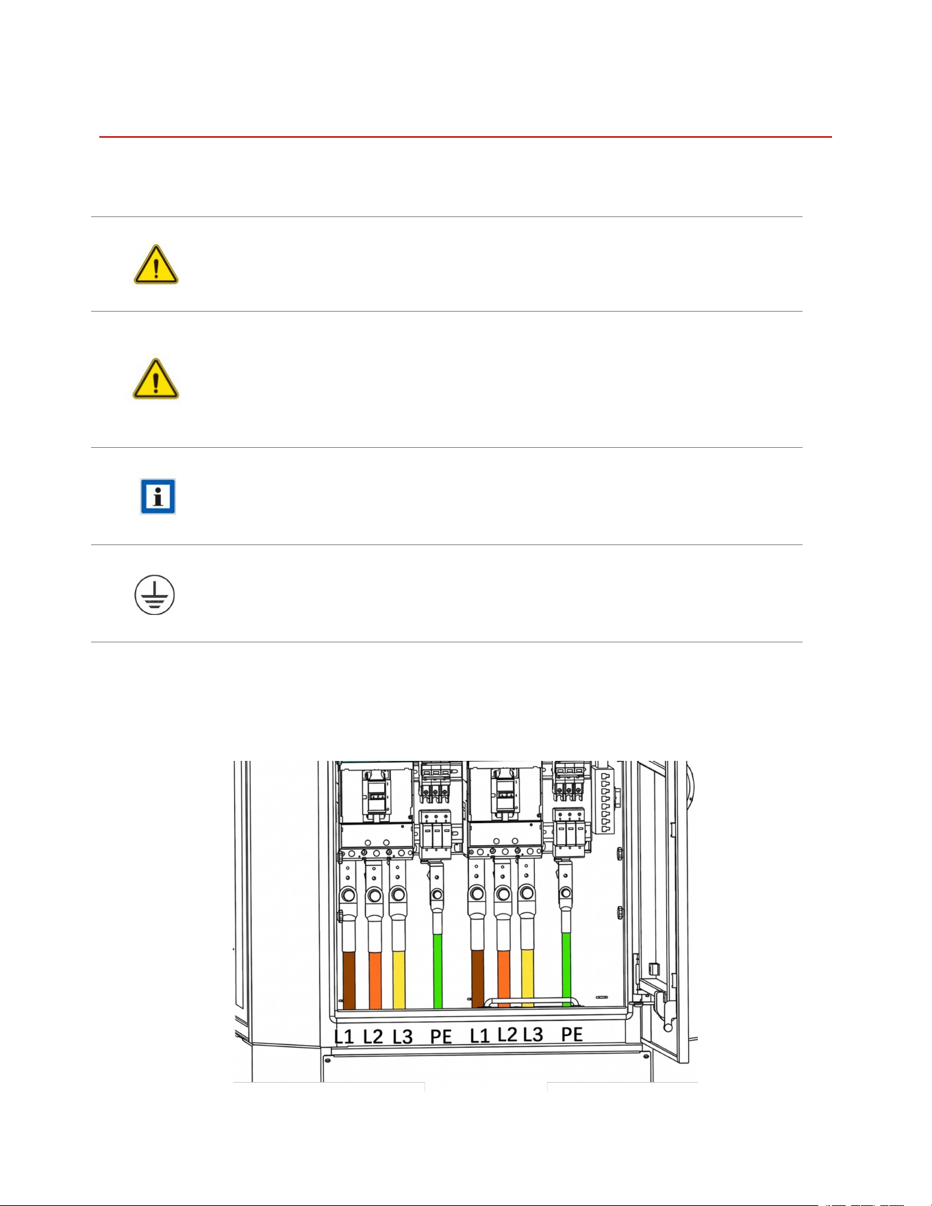
8.1 AC Input Connection
Connect the AC input cables according to terminal markings, and crimp terminals, tighten bolts, and verify torque
as required.
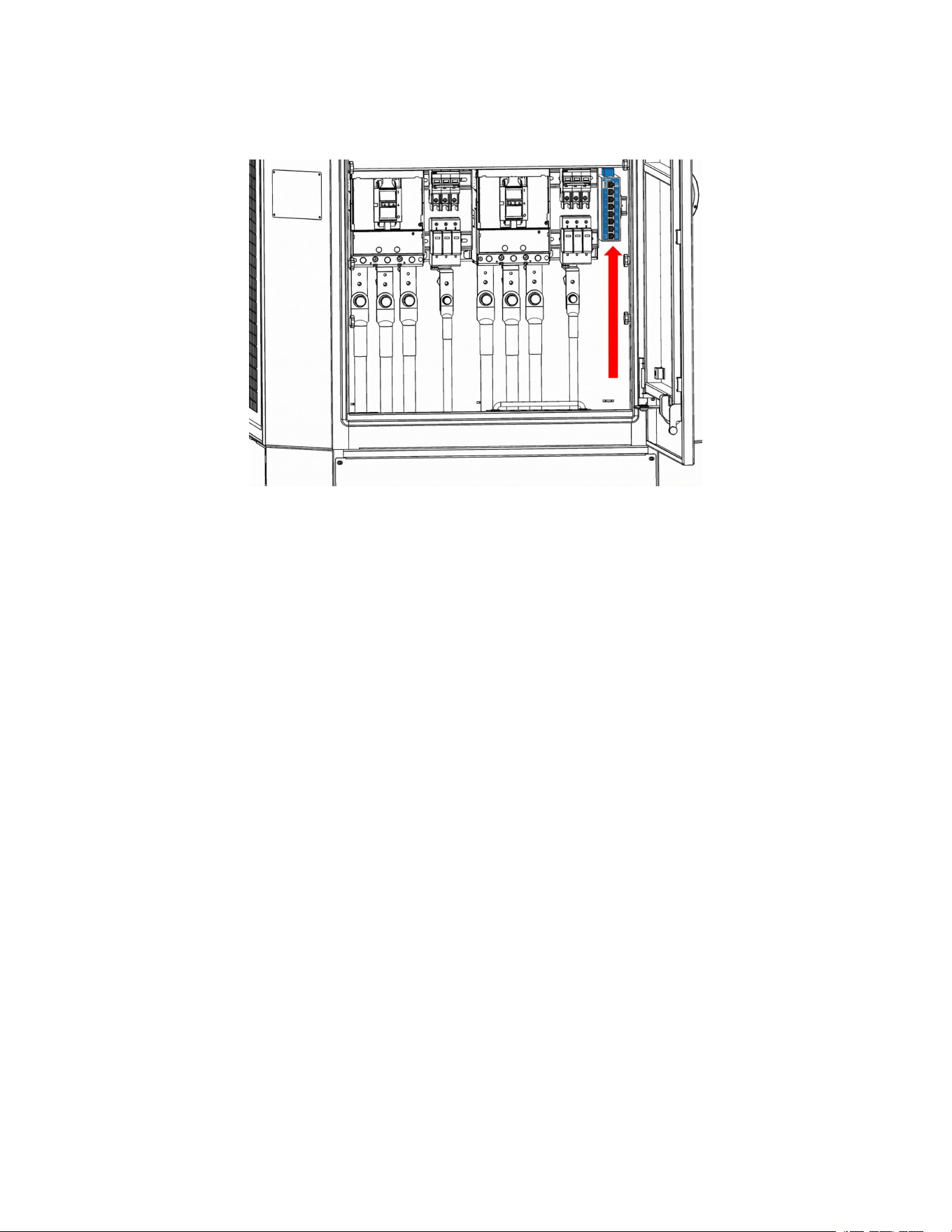
8.2 Communication Connection
Complete the connection of the Ethernet, 4G/5G, or other communication interfaces as shown in the figure.
9. Commissioning and Initial Operation
This chapter describes the first energization, parameter setting, and trial charging verification process. After the
mechanical installation and electrical connection are complete, carry out the pre-energization checks, parameter
confirmation, and functional verification required in this chapter to ensure that the equipment is ready for safe
operation.
WARNING
- Do not energize the equipment for commissioning before the pre-power-on inspection has been
completed.
- If abnormal wiring, failed insulation, abnormal grounding, or foreign objects left inside the cabinet are
found, energization is strictly prohibited.
- If abnormal odor, abnormal noise, smoke, or severe alarms occur during commissioning, immediately
disconnect power and inspect the equipment.
CAUTION
- Before commissioning, confirm that mechanical installation, electrical wiring, and grounding
inspections have all been completed.
- Before first energization, complete insulation testing, grounding continuity testing, and necessary
electrical inspections.
- Commissioning personnel shall be familiar with the operating interface, parameter setting methods,
and emergency power-off measures.
9.1 Power-On Steps
WARNING
Confirm that no one is performing wiring or dismantling work around the equipment.
Close the upstream circuit breaker or power supply switch.
Follow the steps shown in the figure to turn on the corresponding switches in sequence.
Observe the equipment display and status indicators.
Color
LED State
Satellite Status
Green
Solid
Charging
Blue
Solid
Idle
White
Blinking
Reserved
Red
Solid
Fault
Check for fault alarms, abnormal sound, odor, or tripping.
Confirm that the equipment enters the normal standby or initialization screen.
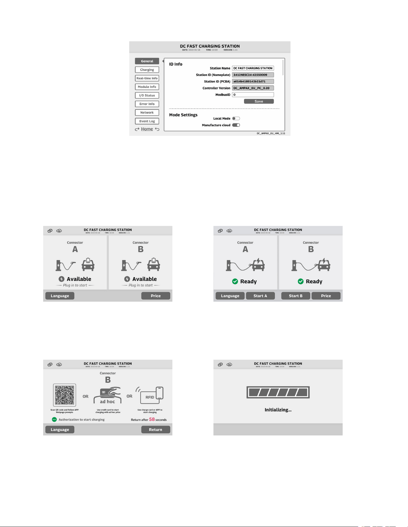
9.2 Basic Parameter Settings
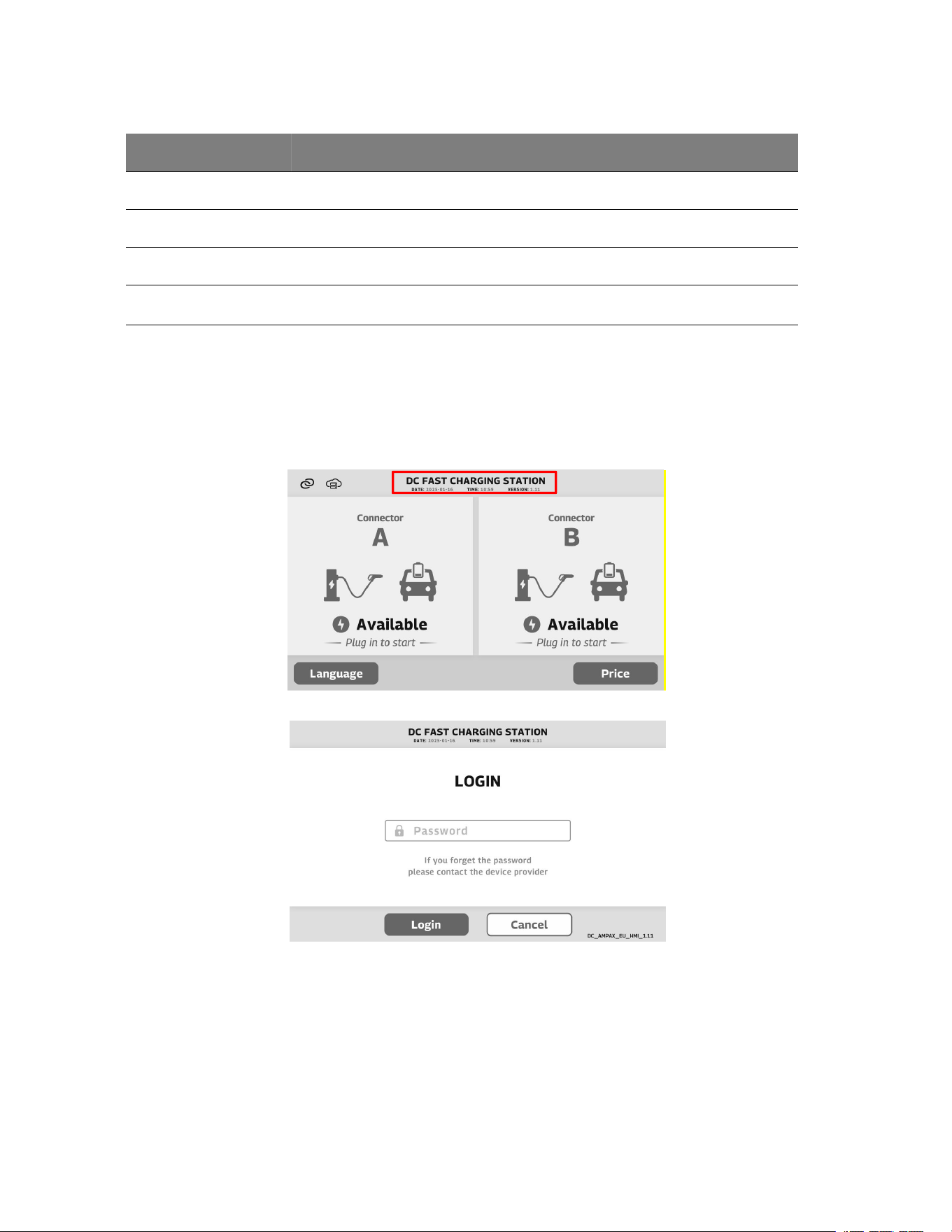
· Double-click the center of the DC FAST CHARGING STATION text to enter the engineer interface for
basic parameter settings.
· Enter password
· As shown below, further configuration can be performed in the engineer interface.
9.3 Charging Procedure
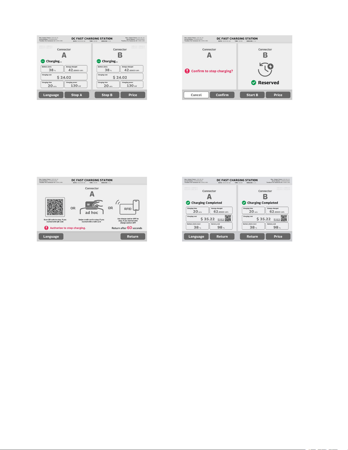
The touchscreen display during normal charging is shown below.
Standby status
Connected status
Select connector for charging;
Click “Start A”/ “Start B” button to start.
Start charging authorization
Swipe RFID card, tap a credit card on the POS
terminal, or scan the QR code with the APP to start
charging
Authorization successful
Wait for charging
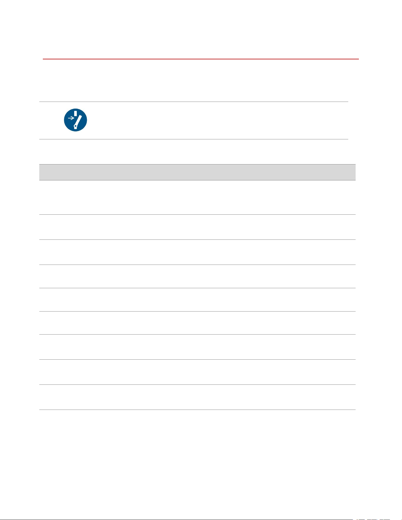
Charging state
Click “Stop Charging” to end charging
Stop charging
Confirm to stop charging
Stop charging authorization
Swipe RFID card, tap a credit card on the POS
terminal, or scan the QR code with the APP to end
charging
Charging complete
Display charging bill
10. Maintenance and Troubleshooting
10.1 Routine Inspection and Maintenance Recommendations
To ensure safe and reliable operation of the equipment, routine inspection and maintenance are recommended at
regular intervals.
Disconnect before carrying out maintenance or repair.
10.1.1 External Inspection
Inspection Item
Inspection Criteria
Frequency
Environment
Check whether the surrounding area is clean and free
from debris, standing water, or other abnormal
conditions.
Once every 3 months
Appearance
Check whether the enclosure is clean and free from
damage, deformation, or corrosion.
Once every 3 months
Charging Cable
Check for wear, cracks, cuts, looseness, or other
damage.
Once every 3 months
Operating Sound
Check for any abnormal sound during operation.
Once every 3 months
Touchscreen
Check whether the touchscreen operates normally.
Once every 3 months
Fan
Check whether the fan operates normally.
Once every 3 months
Filter
Check whether the filter is clean; clean or replace it if
necessary.
Once every 3 months
Small Animal Intrusion
Inspect the cabinet for any intrusion by insects, rodents,
or other small animals.
Once every 3 months
Cable Condition
Check whether any cable shows signs of overheating,
burning, discoloration, looseness, or damage.
Once every 3 months
10.1.2 Internal Inspection
Before performing internal inspection, disconnect the power supply and follow all applicable safety procedures.

Inspection Item
Inspection Criteria
Frequency
Fuse
Check whether the fuse is in good condition and
functions properly.
Once every 3 months
Fastening Screws
Check whether any screws are loose or missing.
Once every 3 months
Water Ingress
Check whether there is any water leakage, moisture,
or condensation inside the cabinet.
Once every 3 months
Power Module
Check whether the power modules operate normally.
Once every 3 months
Internet Connection
Check whether the communication/network
connection functions normally.
Once every 3 months
Charging Test
Perform a charging test to verify normal charging
operation; a test duration of up to 10 minutes is
recommended.
Once every 3 months
10.2 Common Fault Troubleshooting
Fault Code
Fault Information
Troubleshooting
1101
Door Access Protection
Reopen the cabinet door and close it correctly.
Check the connected wires of cabinet door switch.
1102
Emergency Stop
Step 1. Check the emergency stop button. If it is
pressed, turn off the power and check if there are any
abnormalities in the cabinet, such as odor, water
immersion, etc.
Step 2. If all faults are excluded, rotate the emergency
stop button clockwise to reset it.
1103
K1/K2 Fault
Try charging again, if the fault still occurs, the related
components may be damaged.
Replace the K1/K2 relay
1812
Surge Protection Fault
Check the observation window of SPD. If the SPD
turns red, it should be replaced.
Check whether the auxiliary contact connection is
reliable.
1119
AC Contactor Fault
Reboot the input power, if the error persists, the AC
Contactor may be damaged.
Replace the AC Contactor.
1201
Power Module Comm Fault
Check whether the communication cable connection to
the power module is reliable.
If the fault comes from the power module, then replace
the power module.
1202
Energy Meter Comm Fault
Check whether the communication cable connection of
the energy meter is reliable.
If the fault comes from the energy meter, then replace
the energy meter.
1304
DC Output Overvoltage
Check whether the threshold value set on the parameter
setting interface is correct.
1307
High Ambient Temperature
Check whether the air inlet/outlet on the left and right
sides of the cabinet are blocked.
Use non-contact temperature measuring equipment to
check whether any components inside the cabinet are
10.3 Safe Shutdown and Power-Off Procedure
WARNING
Do not touch internal electrical components before confirming that the equipment is completely de-
energized
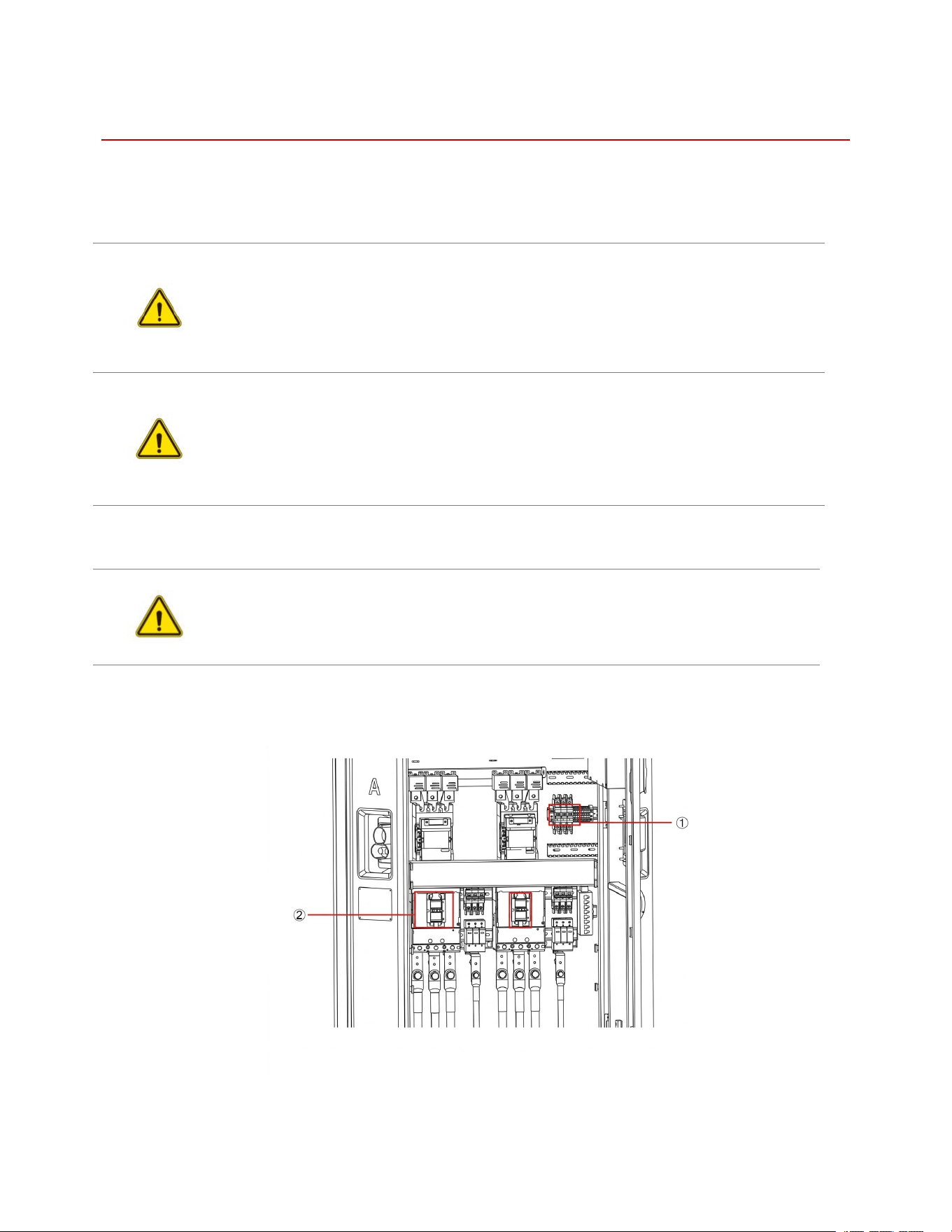
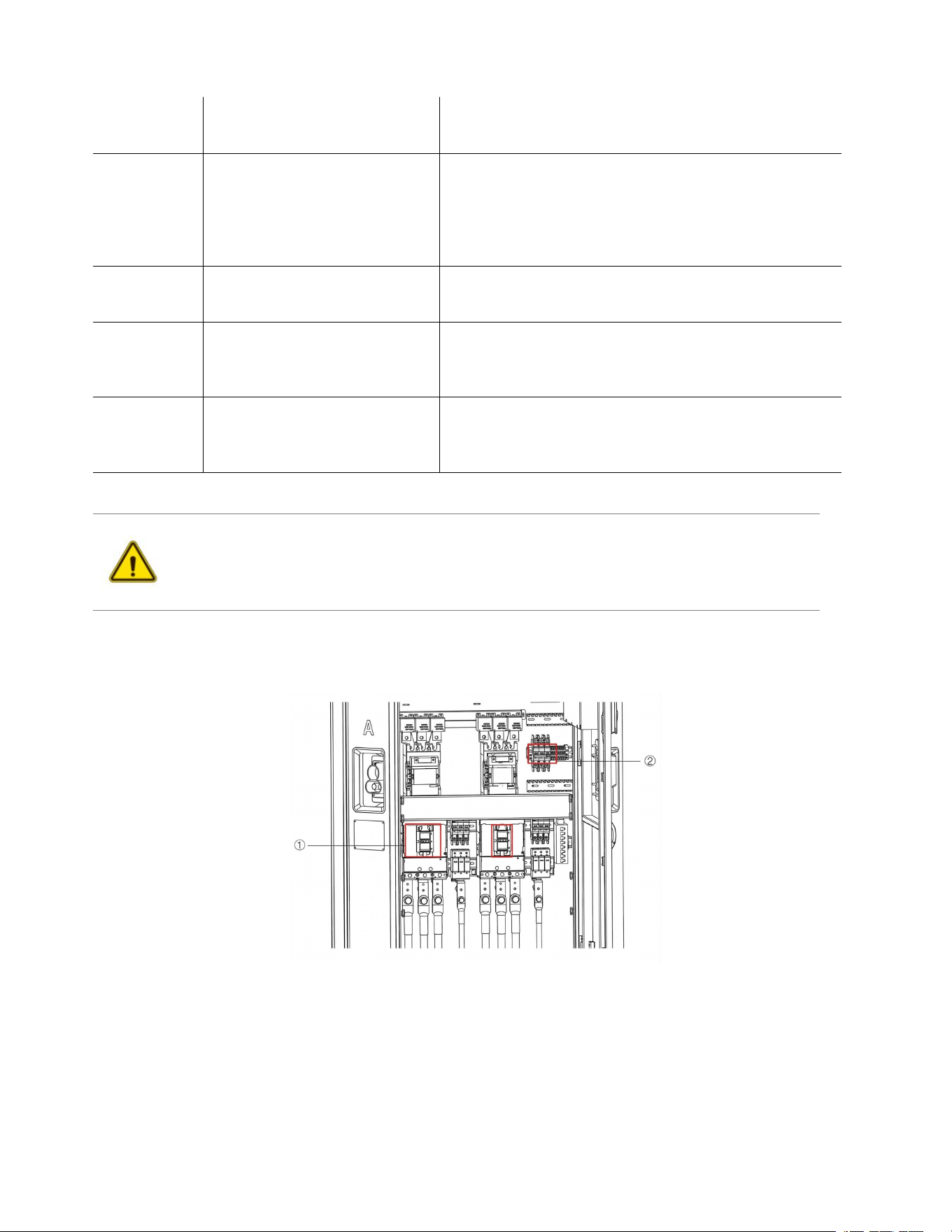
Before maintenance or inspection, make sure the charging session has ended and the vehicle is disconnected. As
shown in the figure, switch off MCCB (①) first, and then switch off (②). Confirm that the charger is fully
powered off before carrying out any further work.
overheated due to abnormal heating.
If none of the above occurs, open the cabinet door to
dissipate heat before restart the charger.
1308
Insulation Fault
If the insulation fault is from the charging electric
vehicle, the fault happens. Try another electric vehicle
to verify.
Power off the main MCCB and reboot to observe if the
fault disappears again.
Check whether the PE connection is reliable.
1310
DC Contactor Ex-voltage > 60V
This fault can come from the charging vehicle. Try
another electric vehicle to verify first.
If the vehicle is normal, then replace the power module.
1313
CP Voltage Abnormal
Check whether the connection of the charging cable is
reliable.
This fault can come from the charging vehicle. Try
another electric vehicle to verify.
1314
Charging Cable Over
Temperature
Check whether the threshold value of cable temperature
set on the parameter setting interface is correct.
Check whether the connection of the charging cable is
reliable.

11. Technical Data and Appendix
11.1 Technical Data Table
INJET HANHUI
DC Output
Output Power
Configurable as 480 kW, 400 kW, 320 kW, 240 kW, 160 kW, 120
kW; Upgradable from 240 kW to 320 kW or 320 kW to 480 kW
Power Module
40kW SiC
Dynamic Power
Sharing
Minimum adjustable power 40–80 kW
Output Voltage
150–1000 V
Output Current
(Nominal)
CCS1/CCS2: 350–400A, 600A; J3400 (NACS): 375A, 600A; GBT:
300A, 600A
Number of Outlets
Dual Outlet
Power Conversion
Efficiency
Up to 97%
AC Input
Nominal Voltage
(CE): 400 Vac ±10%; (NA): 480 Vac ±10%
Frequency
50/60 Hz
Power Factor
>0.99 at full load
Customer
Interface
Display
15.6" HD LCD; (Optional) Type: 32" HD full-color LCD for
Advertising
Languages
English, French, Spanish, German, Italian
Connector Options
CCS1/CCS2 air cooling / liquid cooling options; J3400 (NACS) air-
cooling / liquid cooling options; GBT air-cooling / liquid cooling
options
Cable Management
2 Self-retracting Swing Arms (Enclosure Integrated)
Cable Length
5m (Reach: 4.8) / 7.5m (Reach: 6.1m)
Lighting
Roof: 270° RGB strips; Bevels: LED indicators; Gun holder: RGB
Authentication
Methods
RFID, Plug&Charge (ISO 15118), Credit/Debit Card, Mobile App
RFID System
ISO 14443 A/B, and ISO/IEC 15693
Operating
Temperature
Operating from -30°C to 55°C with derating from 50°–55°; Storage
from -40°C to 70°C; IEC 60721-3-2

Conditions
Altitude
2000m (6562ft)
Humidity
Up to 95%, non-condensing
Noise Level
<65db
Impact Resistance
IK10, NEMA 3R
IP Rating
IP54
Form Factor
Dimensions of
Charger Body
H x W x D = 2250 x 850 x 750 mm
Accessibility
Meets ADA Requirements
Enclosure Type
Stainless Steel
Standards &
Compliance
Safety Certifications
(CE): CE, CB, UKCA; (NA): CSA, FCC/IC, Energy Star
Metering
(CE): MID; (NA): CTEP/NTEP
EMC
(CE): IEC 61851-21-2; (NA): FCC 47 CFR Part 15B (Class A)
Network Connections
(Optional) Dual 4G/5G, Wi-Fi, Ethernet (10/100 Base-T)
OCPP
1.6J and 2.0.1
Vehicle
Communication
Protocol
DIN SPEC 70121, ISO 15118-2, ISO 15118-3, Plug & Charge
RED Directive
ETSI EN 300 330, ETSI EN 301 489-1, ETSI EN 301 489-3, ETSI
EN 301 489-52, ETSI EN 301 908-13, EN 50364 (RFID), IEC
62311: 2019, EN IEC 62311: 2020 (4G test)
Standard Warranty
2 years + SLA Package
Others
Site Level EMS Control
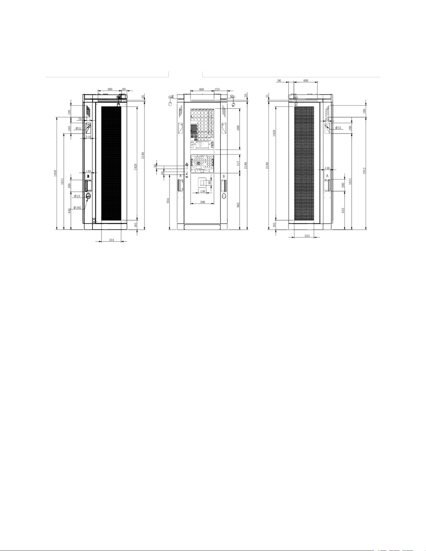
11.2 Overall Dimensions
Unit: mm