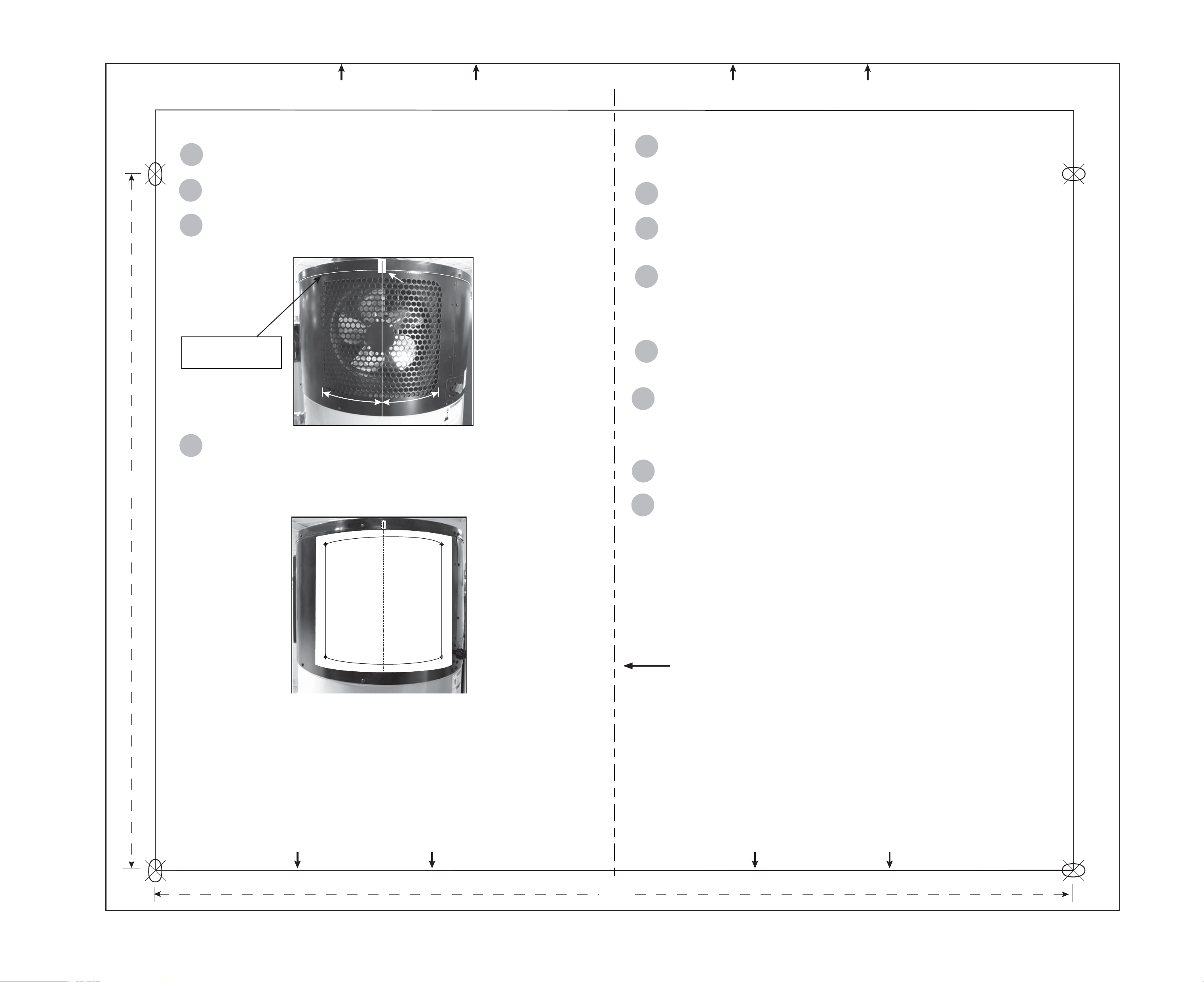
OUTLET VENT TEMPLATE INSTRUCTIONS:
Be sure the electrical power to the water heater is turned OFF at the
circuit breaker panel (or remove the disconnects).
Using a non-contact circuit tester, check the wiring to make certain
the power is OFF.
Locate the vertical center point of the fan outlet. Place a piece of
tape at the “center” location and mark the tape with a pen or marker.
Align the centerline of the template with the “taped” centerline and
the top of the template sheet with the lip edge of the jacket top. NOTICE:
For proper operation the template must be aligned with the center of the
outlets. The vent outlets should not be outside the template borders.
Use a drill and #2 Phillips screwdriver bit to set the self tapping
TOP OF TEMPLATE
CENTER LINE: MATCH WITH CENTER LINE ON UNIT.
screws provided with the kit. NOTICE: DO NOT OVER TIGHTEN THE
SCREWS.
Use the drill and #2 Phillips screwdriver bit to remove the screws.
Set them aside for reuse.
Remove the paper template and place the duct adapter over the
vent. Align the holes in the adapter with the recently drilled holes in the
unit.
Use a drill and #2 Phillips screwdriver bit to secure the duct adapter
to the water heater using provided screws and washers (place washers
on the hole of the adapter, then the screw). Align the screws to use the
drilled holes.
NOTICE: DO NOT OVER TIGHTEN THE SCREWS.
Visually check the duct adapter to make sure it is mounted in the
correct location and correctly aligned. No vents should be visible along
the edges of the duct adapter.
cable tie.
•
NOTICE: DO NOT use with metal or rigid ducting.
•
For total (inlet and outlet) ducting lengths longer than 50’ a duct
booster fan kit must be installed. See part number 100131328.
If all ducting installation is complete, turn on electric power to the
water heater at the circuit breaker panel (or replace the disconnects).
Follow the instructions in your Use & Care Guide to start up your
water heater. Ensure the water heater is set to your desired settings and
all adapter connections are secure.
NOTICE: Ensure ducting vents are open during unit operation.
100269724_2000184501_3000020808_500009560 (VER 01, REV 01)August 2018
TEMPLATE BORDER - NO VENT OUTLETS BEYOND THIS LINE
TEMPLATE BORDER - NO VENT OUTLETS BEYOND THIS LINETEMPLATE BORDER - NO VENT OUTLETS BEYOND THIS LINE
TEMPLATE BORDER - NO VENT OUTLETS BEYOND THIS LINE
ALIGN WITH LIP ON TOP OF UNIT
14”
11”
5
6
7
8
9
2
3
10
11
12
1
4
outlet vent. Use your nger tips to locate the outside edges of the vent
50 GALLON UNITS ONLY
Secure the insulated flexible ducting to the duct adapter with the
ALIGN WITH LIP ON TOP OF UNIT
Align top line
of template here.
TAPE
(with centerline
marked)

OUTLET TEMPLATE INSTRUCTIONS:
Be sure the electrical power to the water heater is turned OFF at the
circuit breaker panel (or remove the disconnects).
Using a non-contact circuit tester, check the wiring to make certain
the power is OFF.
Locate the vertical center point of the fan outlet. Place a piece of
tape at the “center” location and mark the tape with a pen or marker.
Align the centerline of the template with the “taped” centerline and
the top of the template sheet with the lip edge of the jacket top. NOTICE:
For proper operation the template must be aligned with the center of the
outlets. The vent outlets should not be outside the template borders.
Use a drill and #2 Phillips screwdriver bit to set the self tapping
TOP OF TEMPLATE
CENTER LINE: MATCH WITH CENTER LINE ON UNIT.
screws provided with the kit. NOTICE: DO NOT OVER TIGHTEN THE
SCREWS.
Use the drill and #2 Phillips screwdriver bit to remove the screws.
Set them aside for reuse.
Remove the paper template and place the duct adapter over the
vent. Align the holes in the adapter with the recently drilled holes. NO
TICE: THE DUCT ADAPTER FOR 66/80 UNITS MUST USE THE THE
SUPPLIED INSERTS/SPACERS FOR A SEALED FIT.
Use a drill and #2 Phillips screwdriver bit to secure the duct adapter
to the water heater using provided screws and washers (place washers
on the hole of the adapter, then the screws). Align the screws to use the
drilled holes. NOTICE: DO NOT OVER TIGHTEN THE SCREWS.
Visually check the duct adapter to make sure it is mounted in the
correct location and correctly aligned. No vents should be visible along
the edges of the duct adapter.
cable tie.
•
NOTICE: DO NOT use with metal or rigid ducting.
•
For total inlet and outlet ducting lengths longer than 50’ a duct
booster fan kit must be installed. See part number 100131328.
If all ducting installation is complete, turn on electric power to the
water heater at the circuit breaker panel (or replace the disconnects).
Follow the instructions in your Use & Care Guide to start up your
water heater. Ensure the water heater is set to your desired settings and
all adapter connections are secure.
NOTICE: Ensure ducting vents are open during unit operation.
TEMPLATE BORDER - NO VENT OUTLETS BEYOND THIS LINE
TEMPLATE BORDER - NO VENT OUTLETS BEYOND THIS LINETEMPLATE BORDER - NO VENT OUTLETS BEYOND THIS LINE
TEMPLATE BORDER - NO VENT OUTLETS BEYOND THIS LINE
ALIGN WITH LIP ON TOP OF UNIT
66/80 GALLON UNITS
11”
14”
1
2
3
4
5
6
7
8
9
10
11
12
Secure the insulated flexible ducting to the duct adapter with the
ALIGN WITH LIP ON TOP OF UNIT
outlet vent. Use your finger tips to locate the outside edges of the vent.
Align top line
of template here.
TAPE
(with centerline
marked)
INLET TEMPLATE INSTRUCTIONS:
1
Be sure the electrical power to the water heater is turned OFF at the
circuit breaker panel (or remove the disconnects).
2
Using a non-contact circuit tester, check the wiring to make certain the
power is OFF.
and install into duct adaptor. There are 2 tabs (B) (oriented into the top) on the
tabs upward (C).
Mark the center point between 2 screws as shown. Place a piece of tape
at the “center” location and mark the tape with a pen or marker.
Align the centerline of the template with the “taped” centerline and the
top of the template sheet with the center of the two top screws. NOTICE: For
proper operation the template must be aligned with the center of the inlet vent.
Use a drill and #2 Phillips screwdriver bit to set the self tapping screws
TOP OF TEMPLATE
CENTER LINE: MATCH WITH CENTER LINE ON UNIT.
provided with the kit.
NOTICE: DO NOT OVER TIGHTEN THE SCREWS.
Use the drill and #2 Phillips screwdriver bit to remove the screws. Set
them aside for reuse.
Remove the paper template and place the duct adapter over the vent.
Align the holes in the adapter with the recently drilled holes in the unit.
Use a drill and #2 Phillips screwdriver bit to secure the duct adapter to
the water heater using provided screws and washers (place washer on the
hole of the adapter then the screw). Align the screws to use the drilled holes.
NOTICE: DO NOT OVER TIGHTEN THE SCREWS.
Visually check the duct adapter to make sure it is mounted in the correct
location and correctly aligned. No vents should be visible along the edges of
the duct adapter.
tie.
•
NOTICE: DO NOT use with metal or rigid ducting.
•
For total (inlet and outlet) ducting lengths longer than 50’ a duct
booster fan kit must be installed. See part number 100131328.
If all ducting installation is complete, turn on electric power to the water
heater at the circuit breaker panel (or replace the disconnects).
13
Follow the instructions in your Use & Care Guide to start up your water
heater. Ensure the water heater is set to your desired settings and all adapter
connections are secure.
NOTICE: Ensure ducting vents are open during unit operation.
50/66/80 GALLON UNITS
TEMPLATE BORDER - NO VENT INLETS BEYOND THIS LINE
TEMPLATE BORDER - NO VENT INLETS BEYOND THIS LINE
TEMPLATE BORDER - NO VENT INLETS BEYOND THIS LINE
TEMPLATE BORDER - NO VENT INLETS BEYOND THIS LINE
TEMPLATE BORDER - NO VENT INLETS BEYOND THIS LINE
TEMPLATE BORDER - NO VENT INLETS BEYOND THIS LINE
8.75”
9.5”
6”
6”
7”
7”
6
3
4
5
7
8
9
10
11
12
Carefully remove filter from unit by gently pulling (A) from the right side
side of filter opposite the 2 top screws. Install into the adapter with the 2
Secure the insulated flexible ducting to the duct adapter with the cable
TAPE
(center
between
screws)
A
B
C
FRONT OF HEATER
TAPE
(with centerline
marked)
CENTERLINE
FILTER ACCESS
THIS SIDE
