USER MANUAL
USER MANUAL
Sound Processor
4-CHANNEL DSP CONTROLLED
BY A WIRELESS (BT) CONNECTION
TPT-SP4BT

2
Introduction
Thank you for choosing a TIMPANO product!
The TPT-SP4BT is a digital audio processor that oers a variety of high-
precision adjustments and sengs to enhance the performance of
your audio system. Through Bluetooth communicaon, the processor’s
informaon can be viewed and congured remotely using smartphones
with Android or iOS systems. Its digital signal processor (DSP) allows
real-me modicaon of equalizaons, crossover lters, alignment,
gain control, phase inversion, limiter, digital input/output roung, and
other treatments. Its exclusive sequencer feature (SEQUENCER) makes
it possible to congure the programmed startup and shutdown of up to
three products from the remote startup connecons (S1, S2, and S3).
Before installing
Please read this manual carefully.
▪ All connecons must be made with the product turned OFF.
▪ A fuse must be installed between the amplier and the baery is
required to protect against overcurrent. The fuse needs to be installed
as close to the baery as possible. Choose an appropriate fuse for the
amplier based on its consumpon.
▪ Use the wire recommended in this manual to keep cables from
overheang cables and to obtain maximum power.
▪ Keep the cables as short as possible to increase sound delity and
avoid potenal power losses.
▪ Route the installaon cables as far away as possible from the
original vehicle wiring to prevent interference and noise in your
audio system.

3
Features
▪ Graphic input equalizer (15 bands and equalizaon presets);
▪ Input parametric equalizer (frequency, gain, Q factor);
▪ Parametric equalizer per output (frequency, gain, Q factor);
▪ Roung between inputs and outputs;
▪ High precision crossover with Buerworth and Linkwitz-Riley lters
and aenuaons up to 36 dB/8th;
▪ High-precision alignment/delay;
▪ Phase inversion;
▪ Limiter with Threshold, Aack and Release adjustment;
▪ Independent gain and mute per output and master volume;
▪ Working memory with automac saving of sengs;
▪ Allows saving and loading the sengs made by the user;
Security password to block modicaon of the parameters;
▪ Frequency generator, frequency sweep and pink noise;
▪ Outputs for remote triggering with congurable interval;
▪ Baery monitoring;
▪ Limiter actuaon monitoring;
▪ OAD update (over the air download);
If you have quesons , contact the store where the purchase or
installaon was done. For more informaon please contact our
Customer Service: (954) 859-5529
▪ Perform the installaon on a rm surface in a venlated and
dry place.
▪ Installaon should only be done by a qualied professional.
4
Audio Processor TPT-SP4BT
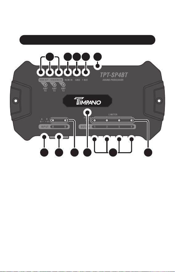
1. REMOTE OUT / SEQUENCER: This feature allows sequenced startup
of other products through your remote connecon (REM). Make the
connecon using a minimum 18 AWG cable. Each connecon can be
congured, enabled or disabled by the applicaon or SMC control.
2. REM IN: Use this connecon for automac processor acvaon when
turning on the radio/player. Connect the remote output of the radio/
player through a cable of at least 18 AWG.
3. NEGATIVE POWER CONNECTOR (GND): Connect to the negave
terminal of the baery through a minimum 13 AWG cable.
Processor Overview
6 7 1098 11
1 2 3 4 5

5
4. POSITIVE POWER CONNECTOR (+BAT): Connect to the posive baery
terminal using a minimum 13 AWG cable. It is recommended to use a 1A
fuse for external protecon.
5. SERVICE CONNECTION: Dedicated connecon for authorized support
services and updates.
6. AUDIO INPUT WITH WIRE CONNECTION (HIGH INPUT): HIGH INPUT
type audio connecon with independent acon (A and B). Check this
manual for the installaon diagram for the radio/player harness.
7. AUDIO INPUT WITH RCA CONNECTION (INPUT): Double type RCA
connectors with independent actuaon (A and B). Connect to the audio
output of the radio/player via RCA cables. Give preference to quality
shielded cables to avoid noise.
8. MAX LEDs (INPUT CHANNELS): These LEDs act individually to indicate
signal saturaon on the input channels.
9. POWER LED / COMMAND BUTTON: Used to reset processor sengs
and updates. See topic “Reset factory sengs”.
10. AUDIO OUTPUTS CHANNELS (OUTPUT): Individual RCA output
connecons provide the audio processed with the parameters
performed in the processor.
11. LIMITER LEDs (OUTPUT CHANNELS): These LEDs actuate when the
“LIMITER” funcon is in use. Each channel has a dedicated LED for
visualizaon of the actuaon individually. The LEDs also act as output
saturaon indicators.
6
SEQUENCER
Outputs for remote
ac va on
Ba ery
Install it close
to the ba ery
(12” max.)
Radio / Player
TIMPANO
- B
- A
INPUT A
INPUT B
HIGH INPUT
(AUTO TURN ON)
BLUE WIRE
WIRE GRAY
AUDIO OUTPUT
S3
S2
S1
Installation
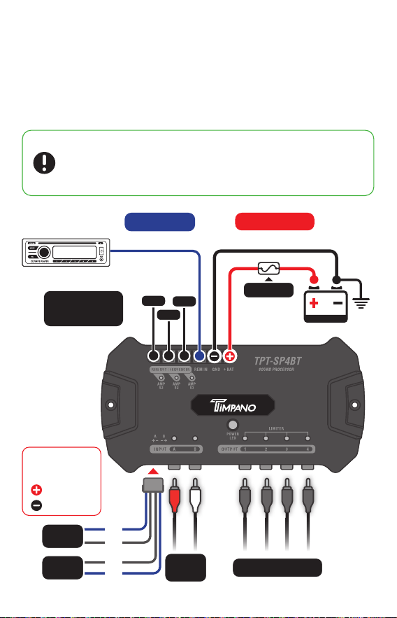
Speci ca on of the cables and fuse for proper installa on:
▪ Power connectors (posi ve/nega ve) .................................
▪ Remote connectors (REM IN / REM OUT ) ..........................
▪ Fuse ......................................................................................
13 AWG
18 AWG
1A
POWER SUPPLY
13 AWG cables
Fuse 1A
REM
18 AWG cable
REM (remote)
INPUT
A B
+ A
+ B
Ground
▪ Installa on must be done only by quali ed professionals with the
product turned OFF.
▪ The use of fuse is mandatory to protect the system from short
circuit and overload. Install them as close to the ba ery as possible.

7
Minimum requirements
▪ Devices with Android system from version 5.0 and Bluetooth
technology 4.0 or higher;
▪ Devices with iOS system from version 12, with Bluetooth
technology 4.0 or higher.
AUTO TURN-ON
It provides the automa c ac va on of the processor through the
signal present in the HIGH INPUT. If the signal level of your radio is not
su cient or when using the RCA connec on, the ac va on must be
done by the remote input (REM IN).
Using the Application
Before you synchronize the TPT-SP4BT with your device, make sure
that it has the minimum requirements to operate correctly with the
processor applica on.
Click to be
directed:
Download the app to your device
In your device’s app store (Play store or App store), search for our
TIMPANO TPT-SP4BT app or use the links below to be directed to the
app page. Once installed, open the app to con gure and use your audio
processor.
Before star ng to sync with the app for the rst me, make sure
the processor is not registered in the list of bluetooth devices
paired with your device. If so, remove it from the list to avoid sync
errors.
Click to be
directed:
8
Pairing with the processor
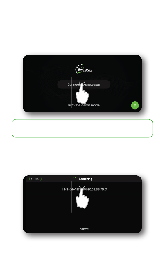
To connect the processor to the applica on via Bluetooth, follow these
instruc ons:
Turn on the TPT-SP4BT and start the APP.
The applica on will start the search and show you available processors
in the pairing list. Select your processor to con nue.
Demo mode allows you to use the applica on without processor
connec on (some func ons will be unavailable in this mode).
9
Before you start the upgrade process::
▪ DO NOT disconnect the processor from power during this process.
▪ DO NOT exit or close the application during this process.
▪ DO NOT distance the device connected to the processor during this
process.
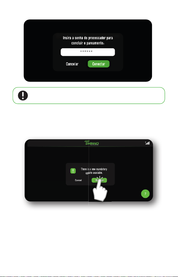
Enter the security password and click connect.
When using the TPT-SP4BT processor for the rst me, it is necessary to
install some func ons and updates. This process is quick and mandatory
to ensure the best performance of the processor.
The default password for pairing is: 123456. For added security,
change the password later in the se ngs menu.
10
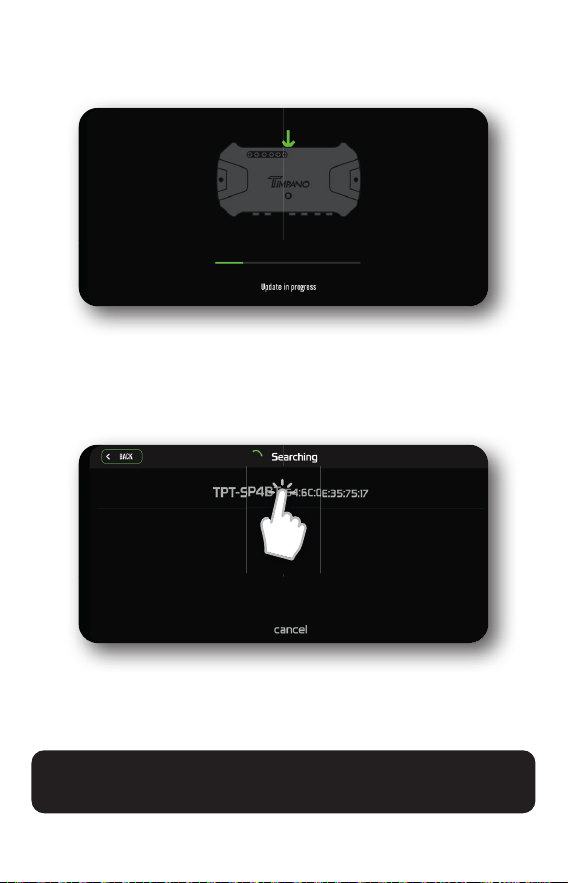
A er star ng the processor update process, wait for the automa c
comple on of this process.
When completed, the processor will automa cally restart and the
applica on will be directed to the search screen to reconnect the
processor.
With the connec on successfully established, the applica on will be
directed to the main menu and will be ready for use.
If you are having diffi cul es or problems con guring the processor, please
contact your installer or our Customer Service team.
11
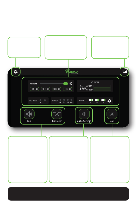
Se ngs
Change app
and processor
preferences.
Audio adjustments
▪ Eq. Graphic
▪ Eq. parametric
▪ Crossover
▪ Rou ng
▪ Gain
▪ Limiter
▪ Delay
▪ Phase
Processor Tools
▪ Audio Generator
▪ Con gura on of
the Sequencer
▪ Save/Copy
▪ Voltmeter
Connec on status
Connec on status
and opens the device
list if pressed.
Shortcuts panel
Simpli ed real- me
control and visualiza on
of processor resources.
Customizable
shortcuts
Customize these
shortcuts for a se ng
or tool of your choice.
They can be changed
whenever you wish in
the se ngs menu.
APP functions and features
Learn about some of the func onali es and features present in the
main screen of the applica on.
In the se ngs menu, you can access technical support and
assistance op ons if necessary.

12
Reset factory settings
It is possible to restore the factory image of the processor. This is
important if the user forgets the pairing password or the processor has
some other problem that does not allow the connecon.
To reset, follow these steps:
1. Turn o the audio processor.
2. Press and hold the control buon and turn on the processor.
3. Release the control buon as soon as its LED starts blinking. Press it
again within 20 seconds to conrm the reset.
4. Aer the reset is conrmed, you will need to update the processor to
the most current rmware version.
Before you start syncing with the applicaon for the rst me or
when it is reset, check that the processor is not registered in the
list of Bluetooth devices paired to your device. If it is, remove it
from the list to avoid synchronizaon errors.

13
Troubleshooting
PRODUCT DOES NOT TURN ON:
▪ Check that the cables are connected correctly. Make sure that all
connecons have electrical and mechanical contact.
▪ Fuses or circuit breakers may be defecve or blown. Check the
condion of the circuit breakers and whether it is compable with the
consumpon of the equipment.
▪ Check that the baery charge is sucient for operaon.
▪ No signal from the REMOTE IN input. Check that the remote
connecon is receiving voltage close to 12V.
ICON INDICATING CONSTANT LOADING:
▪ Possible connecon problem with the processor. Redo the connecon
via the connecon icon (top right icon).
BLUETOOTH NOT VISIBLE / CANNOT PAIR:
▪ Close the applicaon, turn Bluetooth o and on the device and open
the applicaon again.
▪ Turn the processor o and on.
NO SOUND:
▪ Check that the GAIN and LEVEL controls of the inputs and outputs.
▪ Check that the outputs are not o/mute.
▪ The speaker cables or RCA plugs may not be connected correctly or
may be defecve.
NOISES AND GLITCHES IN THE SOUND:
▪ Check that the installaon is not close to the vehicle’s original wiring,
they can cause interference and noise in the audio signal.
▪ Make a separate power connecon for the sound system. Use a fuse/
circuit breaker as close as possible to the baery for protecon.
Do a good grounding of the amplier. For this remove the paint from
the vehicle chassis at the desired point. Screw on the wire using a
ground terminal. To protect it from oxidaon, insulate it with paint.
Do not make a ground loop using several grounds. Prefer the star
connecon, with all grounds starng from a single point.

14
FCC Warning
This device complies with part 15 of the FCC Rules. Operaon is subject
to the following two condions:
(1) This device may not cause harmful interference, and (2) this device
must accept any interference received, including interference that may
cause undesired operaon.
Note: This equipment has been tested and found to comply with the limits
for a Class B digital device, pursuant to part 15 of the FCC Rules. These
limits are designed to provide reasonable protecon against harmful
interference in a residenal installaon. This equipment generates, uses
and can radiate radio frequency energy and, if not installed and used in
accordance with the instrucons, may cause harmful interference to
radio communicaons. However, there is no guarantee that interference
will not occur in a parcular installaon. If this equipment does cause
harmful interference to radio or television recepon, which can be
determined by turning the equipment o and on, the user is encouraged
to try to correct the interference by one or more of the following
measures:
—Reorient or relocate the receiving antenna.
—Increase the separaon between the equipment and receiver.
—Connect the equipment into an outlet on a circuit dierent from that
to which the receiver is connected.
—Consult the dealer or an experienced radio/TV technician for help.
Note: The Grantee is not responsible for any changes or modicaons
not expressly approved by the party responsible for compliance. such
modicaons could void the user’s authority to operate the equipment.
The device has been evaluated to meet general RF exposure requirement.
To maintain compliance with FCC’s RF exposure guidelines, the distance
must be at least 20 cm between the radiator and your body, and fully
supported by the operang and installaon.
FCC ID: 2BBF7-TPT-SP4BT

15
Technical Specifi cations
Number of channels:
Graphic equalizer:
Graphic equalizer presets:
Parametric equalizer:
Crossover with freq. Variable:
Crossover presets:
Rou ng between input / output:
Alignment:
Phase inversion:
Limiter:
Master level:
Output gain:
Frequency generator:
Frequency scan:
Pink noise generator:
Ba ery voltage monitor:
Password:
Input impedance:
Output impedance:
Signal to noise ra o:
Total harmonic distor on:
Channel separa on:
Frequency response:
Max. Input voltage:
Max. Output voltage:
Input: 2 x RCA (A+B) or 2 x HIGH INPUT (A+B)
Output: 4 (1, 2, 3, 4)
15 Bands (gain ±12dB)
12
5 Bands (1 Input + 4 Output)
(gain ±12dB, Factor Q 0.4 a 10.0)
Bu erworth: 12/18/24/36 dB/8ª
Linkwitz-Riley: 12/18/24/36 dB/8ª
11
A, B ou A+B
0ms ~ 8ms (275cm)
0° ~ 180°
Threshold: -24dB ~ 0dB
A ack: 0.1ms ~ 100.0ms e Release:
1ms ~ 1600ms (manual or auto.)
0 ~ 100%
-45dB ~ +15dB per output
10Hz ~ 22kHz and Level -60 ~ 0dB
Star ng and ending frequency: 10Hz ~ 22kHz
Level: -60dB ~ 0dB
Gain: -60dB ~ 0dB
Current, minimum and maximum voltage
6-digit password
RCA: 28 kΩ / FIO: 1 kΩ
47 Ω
> 90dB
< 0,01% T.H.D.
> 80dB
10Hz ~ 22kHz @ 0dB
RCA: 5,6 Vpp (+8,2 dBu)
HIGH INPUT: 15 Vpp (+18 dBu)
5,6 Vpp (+8,2 dBu)

16
Power supply:
Max. Output current SEQUENCER:
Rated current consump on:
Maximum current consump on:
Protec on:
Bluetooth version:
Range:
Compa bility:
Dimensions (H x W x L):
Weight:
10V ~ 15V DC
180 mA per output
170mA @ 12.6V DC
710mA @ 12.6V DC
Short Circuit (PTC fuse)
Low Energy (LE)
15 meters*
Android 5.0 or higher
iOS 12 or higher
1.3” x 3,8” x 7,4”
0.40 Lb
*unobstructed viewable area.
Images contained in this manual are merely illustra ve and may diff er from the actual
product.
Any updates made in this manual will be available for costormers to consult without
any charge on the brand’s site.
It is recommended that the updated manual be consulted whenever needed.

19529 - R2