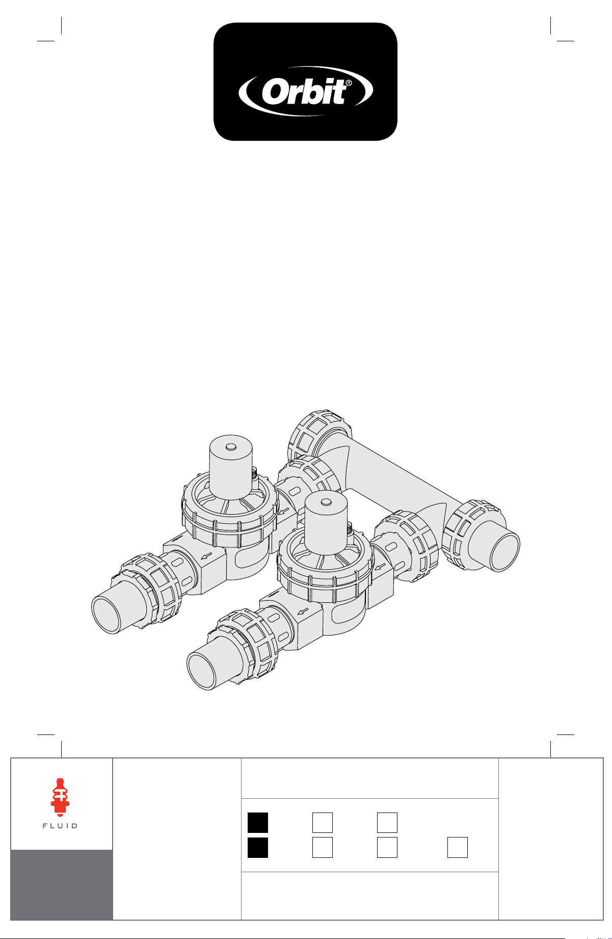
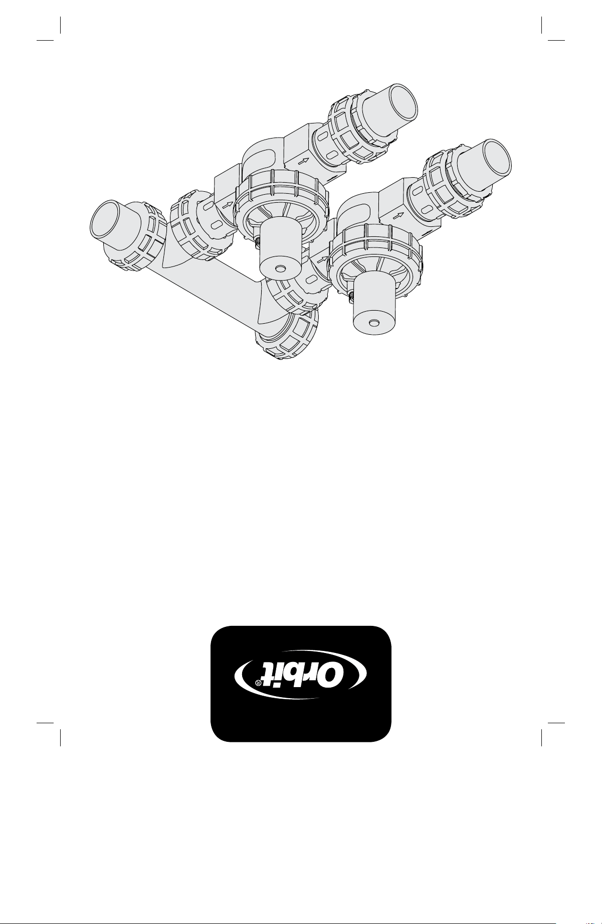
Sprinkler ValVe SyStem
inStruction manual
p 801 295 9820
f 801 951 5815
www.fluid-studio.net
1065 South 500 West
Bountiful, Utah 84010
proof no: 3
date: 09.16.09
des: SM spck: XX
job no: NA
client: Orbit
sku: 57250
upc:NA
file name:
57250-24 rB.indd
software: InDesign CS3
colors
additional instructions:
· Font sizes cannot be smaller than 7 pt.
· Translation Approval code: LB410377
·
color
non printing
PMS
????
PMS
????
color
non printing
PMS
????
Registration
K
Printers are responsible for
meeting print production
requirements. Any changes
must be approved by the
client and Fluid Studio.
printed piece must meet
designated specifications
on this form.
dimensions:
flat: w: 12" h: 8.5"
finished: w 6" d: " h 8.5"
© 2007 Fluid Studio. This
work is the property of Fluid
Studio, and cannot be used,
reproduced or distributed
in any way without their
express permission.
important Guidelines
• Warning:DONOTusepipedopeonthreads,usethreadsealtape
• Placethemanifoldsothatwaterdrainsawayfromthehouse
• Ifnotusingculinarywater,installalterupstreamofthemanifold
Valve placement
1. SelectalocationfortheSprinklerValveSystem
withthefollowingcriteria:
• Accessibletowatersupplyline
• Accessibletosprinklerwirefromtimer
• Elevatedground—avoidlowareaswherewaterwillaccumulate
invalvebox
2. UseanOrbit
®
valvebox(notincluded)toprotectthesprinklervalvesystem
3. Oncealocationisselected,digaholeinthegrounddeepenoughso
thetopofthevalveboxwillbeatandlevelwiththesurface.
Tip:Orbit
®
recommendsplacing1"to1½"ofgravelbelowthevalve
boxfordrainage
installation
1. Checkeachttingconnectionto
makesureitishand-tight.
Warning:DONOTusewrenches,
channellocks,orothertoolsto
tightenttings
2. Checktomakesurethattheow
directionarrow(locatedonthe
bodyofthevalve)ispointedaway
fromthemanifold
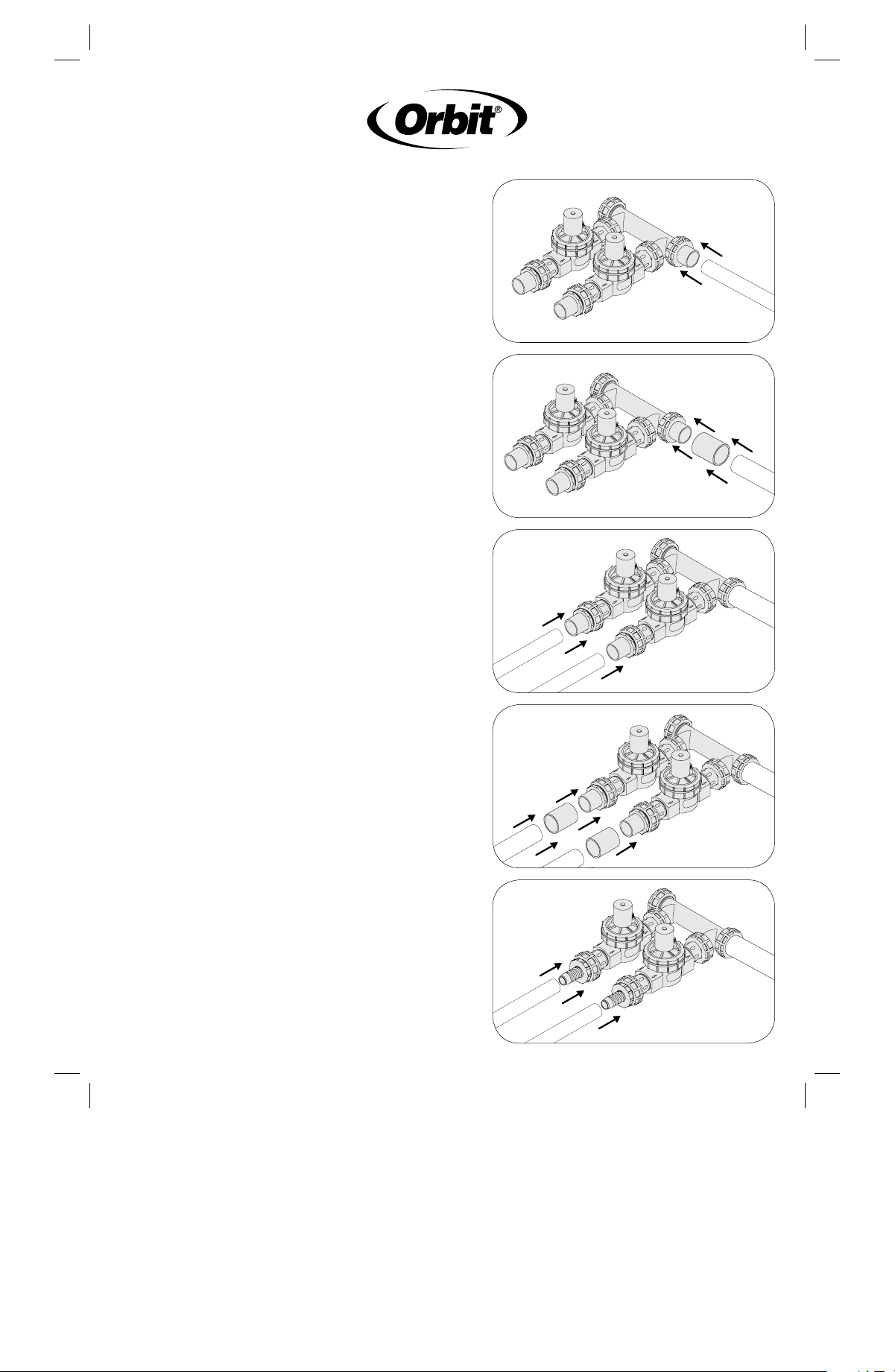
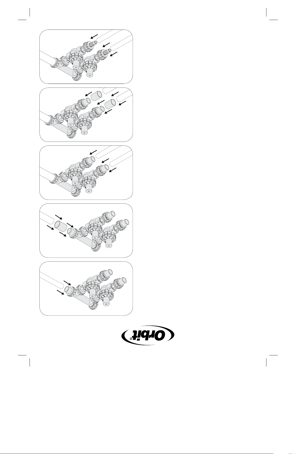
3. ConnectthemanifoldtoPVC
mainlineusingPVCcement
• For¾"PVCpipe,connect
directlytoSwivelAdapter(C)
(Figure 1)
• For1"PVCpipe,useaCoupler
(H)betweenPVCSwivelAdapter
andpipe(Figure 2)
• Forlargersizemainline,
purchaseandinstallreducer
4. ConnectyourSprinklerValve
Systemtoyoursprinklerheader
lines(sprinklerlinesdirectlyafter
thevalve)
• For¾"PVCpipe,connect
directlytoTransitionAdapter(F)
(Figure 3)
• For1"PVCpipe,useCoupler
(H)betweenTransitionAdapter
andpipe(Figure 4)
• For¾"or1"PolyPipe,use
PolyAdapter(includedin
91207/91206)andsecurewith
tubingclamp(Figure 5)
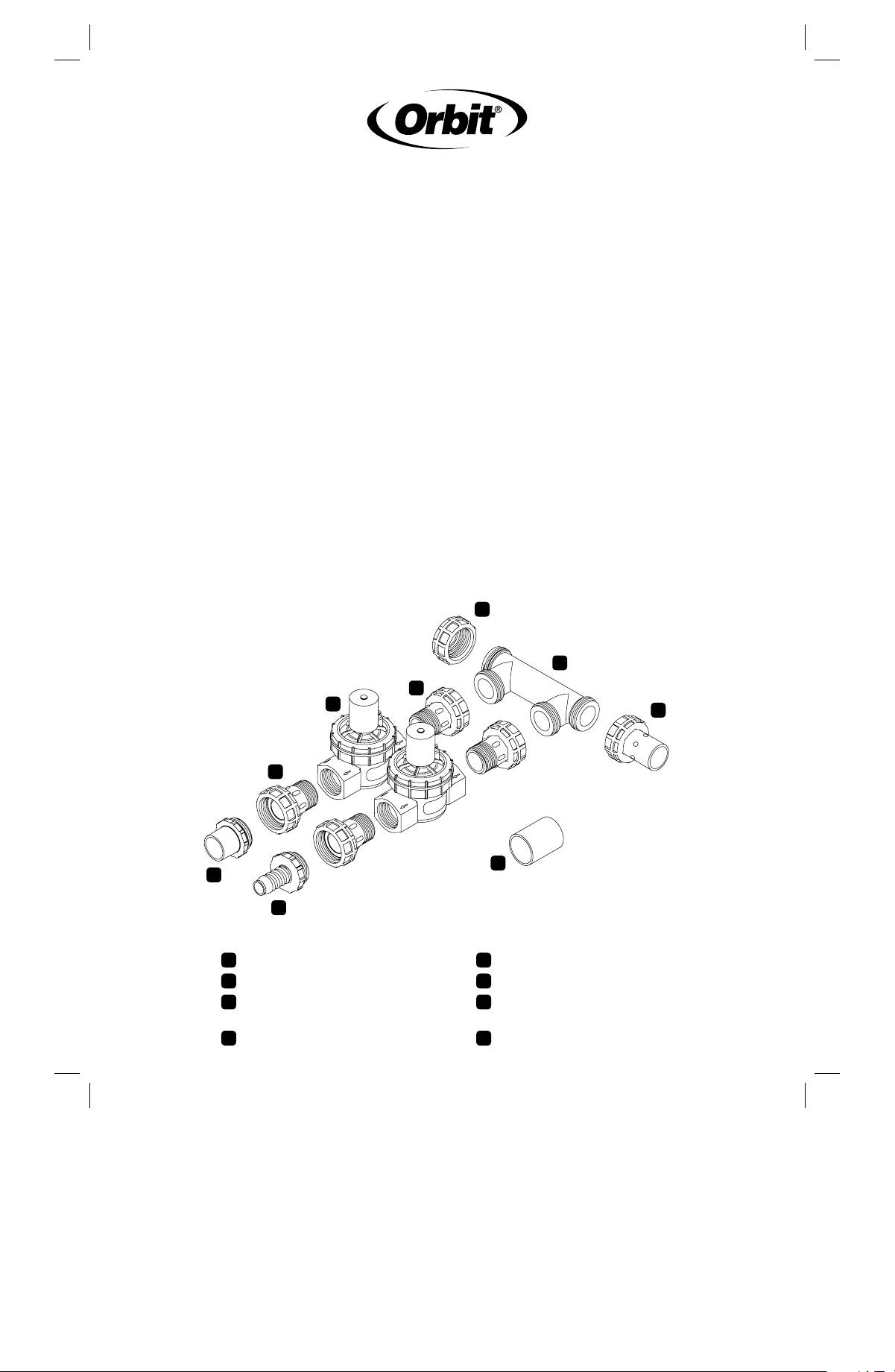
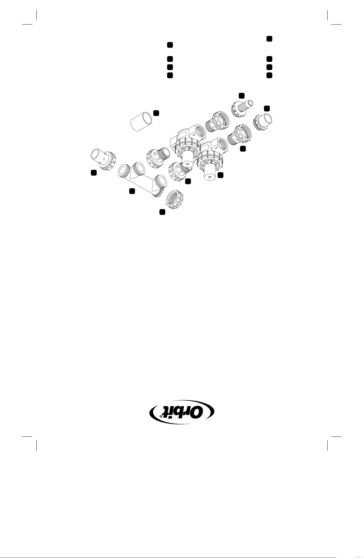
End Cap
1, 2, or 3 Port Manifold
PVC Swivel Adapter
(connects to sprinkler mainline)
1" Swivel Adapters
1" Female Thread Valve
PVC Transition Adapter
¾" or 1" Poly Adapter
(not included)
Coupler
A
A
F
E
G
F
HD
G
H
B
B
C
C
E
D
D
important Guidelines
• Warning:DONOTusepipedopeonthreads,usethreadsealtape
• Placethemanifoldsothatwaterdrainsawayfromthehouse
• Ifnotusingculinarywater,installalterupstreamofthemanifold
Valve placement
1. SelectalocationfortheSprinklerValveSystem
withthefollowingcriteria:
• Accessibletowatersupplyline
• Accessibletosprinklerwirefromtimer
• Elevatedground—avoidlowareaswherewaterwillaccumulate
invalvebox
2. UseanOrbit
®
valvebox(notincluded)toprotectthesprinklervalvesystem
3. Oncealocationisselected,digaholeinthegrounddeepenoughso
thetopofthevalveboxwillbeatandlevelwiththesurface.
Tip:Orbit
®
recommendsplacing1"to1½"ofgravelbelowthevalve
boxfordrainage
installation
1. Checkeachttingconnectionto
makesureitishand-tight.
Warning:DONOTusewrenches,
channellocks,orothertoolsto
tightenttings
2. Checktomakesurethattheow
directionarrow(locatedonthe
bodyofthevalve)ispointedaway
fromthemanifold
3. ConnectthemanifoldtoPVC
mainlineusingPVCcement
• For¾"PVCpipe,connect
directlytoSwivelAdapter(C)
(Figure 1)
• For1"PVCpipe,useaCoupler
(H)betweenPVCSwivelAdapter
andpipe(Figure 2)
• Forlargersizemainline,
purchaseandinstallreducer
4. ConnectyourSprinklerValve
Systemtoyoursprinklerheader
lines(sprinklerlinesdirectlyafter
thevalve)
• For¾"PVCpipe,connect
directlytoTransitionAdapter(F)
(Figure 3)
• For1"PVCpipe,useCoupler
(H)betweenTransitionAdapter
andpipe(Figure 4)
• For¾"or1"PolyPipe,use
PolyAdapter(includedin
91207/91206)andsecurewith
tubingclamp(Figure 5)
Figure 1
Figure 2
Figure 3
Figure 4
Figure 5
“easy Wire” connection
Note:The“EasyWire”Systemshould
onlybeusedon24-Voltsprinklertimers
withClassIIcircuits.Allwiringmust
conformtoapplicablelocalcodes.
1. Disconnectpowertoyoursprinkler
timer
2. Runsprinklerwire(use16ga–20ga
wire)fromyourtimertothe
manifoldassembly
3. Remove4"–5"oftheouter
insulationofthesprinklerwire
Warning:Avoidcuttingintothe
wiresinside
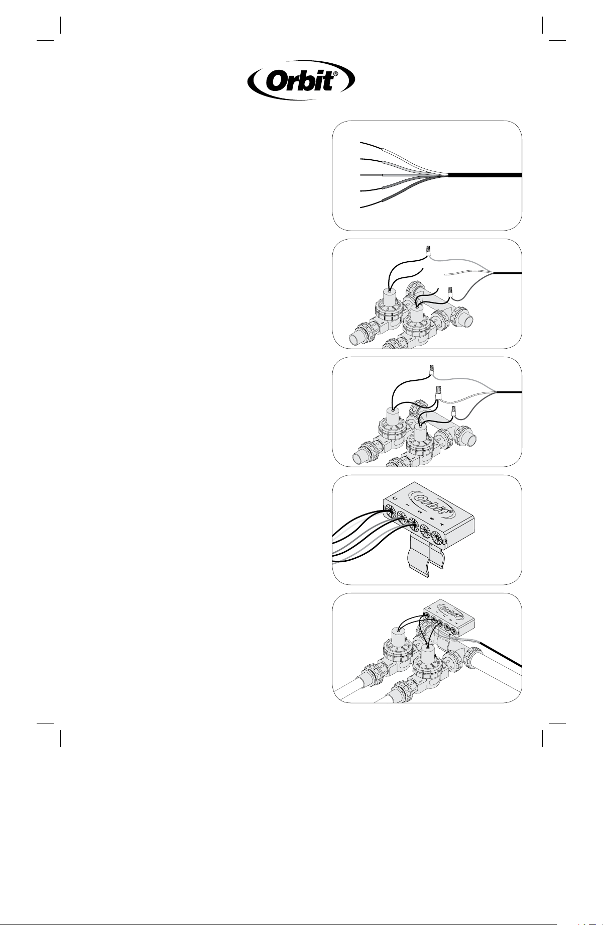
4. Remove7/8"–1"ofinsulationfrom
eachindividualwire(Figure 6)
5. Insertonewirefromthevalveand
acoloredwirefromthetimerinto
thewirenutandtwisttolockthe
wiresinthewirenut.Onewire
shouldbeusedforeachzonewith
anadditionalwiretobeusedfora
common(foreaseofidentication,
usethewhitewireasthecommon).
Note:Thewireshouldholdrm
whenlightlypulled.Ifthewire
movesfreely,removethewireand
repeatStep5.(Figure 7)
6. Takethesecondwirefromeach
valveandthewhitecommonwire
fromthetimerandtwisttheminto
thewirenut(Figure 8)
7. Inserteachwirenutintothe
correspondingcavityinsidethe
“EasyWire”Organizer(Figure 9)
8. Slidethe“EasyWire”Organizeronto
themountingbracketandattachto
thevalvemanifold(Figure 10)
testing
Warning:Beforeproceeding,makesurecementedjointshavereachedthe
recommendedcuringtime(variesaccordingtomanufacturer).
1. EnsuretheManualBleedScrewsonthevalvesarefullyclosed(turn
clockwiseuntilhand-tight).
2. Turnonsprinklersupplylineandcheckmanifoldandvalveforleaks.If
anyleakoccurs,LIGHTLYtightenconnectionswithchannellocksuntil
theleakstops.DONOTover-tightenswivels.
3. TurnManualBleedScrewcounterclockwiseuntilwaterowsout—run
for20secondsandturnclockwisetoretighten.Repeatwithallvalves.
4. Checkthatthesprinklertimerispluggedinand/orthecircuitbreaker
ison.Runeachstationmanuallyfromthetimertoverifyelectrical
connectiontothevalve.
Figure 8
Figure 9
Figure 10
Figure 6
Figure 7
“easy Wire” connection
Note:The“EasyWire”Systemshould
onlybeusedon24-Voltsprinklertimers
withClassIIcircuits.Allwiringmust
conformtoapplicablelocalcodes.
1. Disconnectpowertoyoursprinkler
timer
2. Runsprinklerwire(use16ga–20ga
wire)fromyourtimertothe
manifoldassembly
3. Remove4"–5"oftheouter
insulationofthesprinklerwire
Warning:Avoidcuttingintothe
wiresinside
4. Remove7/8"–1"ofinsulationfrom
eachindividualwire(Figure 6)
5. Insertonewirefromthevalveand
acoloredwirefromthetimerinto
thewirenutandtwisttolockthe
wiresinthewirenut.Onewire
shouldbeusedforeachzonewith
anadditionalwiretobeusedfora
common(foreaseofidentication,
usethewhitewireasthecommon).
Note:Thewireshouldholdrm
whenlightlypulled.Ifthewire
movesfreely,removethewireand
repeatStep5.(Figure 7)
6. Takethesecondwirefromeach
valveandthewhitecommonwire
fromthetimerandtwisttheminto
thewirenut(Figure 8)
7. Inserteachwirenutintothe
correspondingcavityinsidethe
“EasyWire”Organizer(Figure 9)
8. Slidethe“EasyWire”Organizeronto
themountingbracketandattachto
thevalvemanifold(Figure 10)
testing
Warning:Beforeproceeding,makesurecementedjointshavereachedthe
recommendedcuringtime(variesaccordingtomanufacturer).
1. EnsuretheManualBleedScrewsonthevalvesarefullyclosed(turn
clockwiseuntilhand-tight).
2. Turnonsprinklersupplylineandcheckmanifoldandvalveforleaks.If
anyleakoccurs,LIGHTLYtightenconnectionswithchannellocksuntil
theleakstops.DONOTover-tightenswivels.
3. TurnManualBleedScrewcounterclockwiseuntilwaterowsout—run
for20secondsandturnclockwisetoretighten.Repeatwithallvalves.
4. Checkthatthesprinklertimerispluggedinand/orthecircuitbreaker
ison.Runeachstationmanuallyfromthetimertoverifyelectrical
connectiontothevalve.
Figure 8
Figure 9
Figure 10
Figure 6
Figure 7
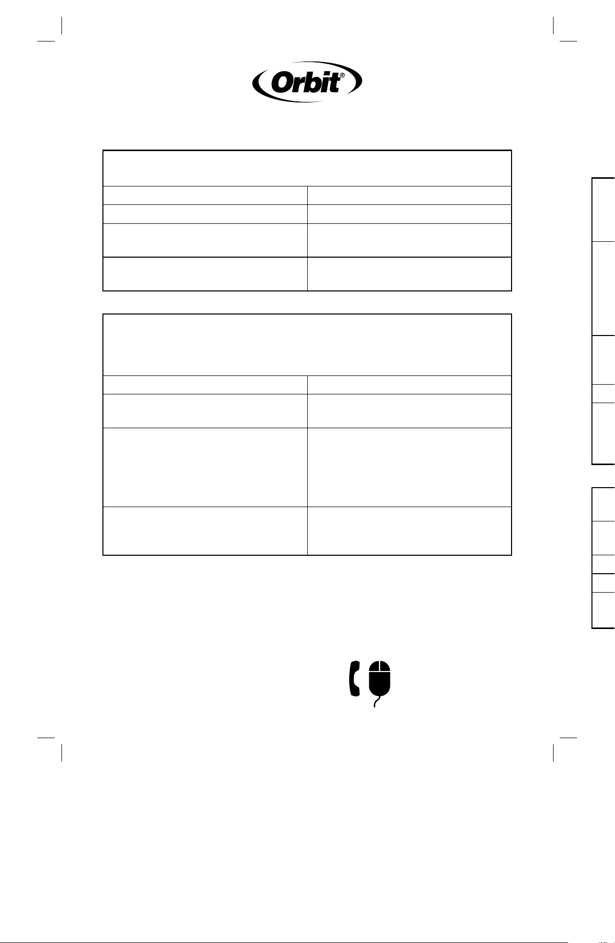
Manifold System leaks at connections
Check Solution
Connectionsareloose Retightenconnections
O-ringisoutofplace,damaged,
ormissing
Replaceo-ringinproperplace
Waterpressureexceeds80PSI
Installapressureregulator
upstreamofmanifold
The valve does not open electrically (but opens using the bleed screw)
and sprinkler timer is functioning
Check Solution
Individualsprinklerwire
pullsouteasily
UntwistwiresandfollowStep5in
“EasyWire”Connection
Bareindividualsprinklerwire
extendsbeyondprotective
membrane
Removewireandensurethebare
wireisnotshorterthan7/8"and
nomorethan1"inlength.Untwist
wiresandfollowStep5in“Easy
Wire”Connection
IndividualSprinklerwiresare
heldrmlyinplacebutarenot
contactingbarewire
Ensurethebaresprinklerwireis
notshorterthan7/8"andnomore
than1"inlength.
Orbit
®
Irrigation Products Inc.
North Salt Lake, Utah 84054 USA
www.orbitonline.com
1-800-488-6156
PN 57250-24 rB
Solución de problemas
El sistema del tubo colector tiene fugas en las conexiones
Revise Solución
Lasconexionesestánsueltas Vuelvaaapretarlasconexiones
Lajuntatóricaestádañada,en
posiciónincorrectaonoestá
Pongalajuntatóricaen
sulugarnuevamente
Lapresióndeagua
superalos80PSI
Instaleunreguladordepresión
aguasarribadeltubocolector
La válvula no se abre eléctricamente (pero se abre utilizando el tornillo
de purga) y el temporizador del regador está funcionando
Revise Solución
Elconductordecadaregador
sesaleconfacilidad
Separelosconductoresy
procedaconelpaso5en
Conexión“EasyWire”.
Losconductorespelados
individualesdelregadorse
extiendenhastamásalláde
lamembranaprotectora
Retireelconductoryasegúrese
dequeelconductorpeladotenga
unalongitudmínimade2,2cm
ymáximade2,5cm.Separelos
conductoresyprocedaconelpaso
5enConexión“EasyWire”.
Losconductoresdecadaregador
estánrmesensulugarpero
notienencontactoconlos
conductorespelados
Asegúresedequeelconductor
peladodelregadortengauna
longitudmínimade2,2cmy
máximade2,5cm
troubleshooting
CUSTOMER SERVICE
1-800-488 -6 156
www.orbitonline.com
CUSTOMER SERVICE
1-800-488 -6 156
www.orbitonline.com
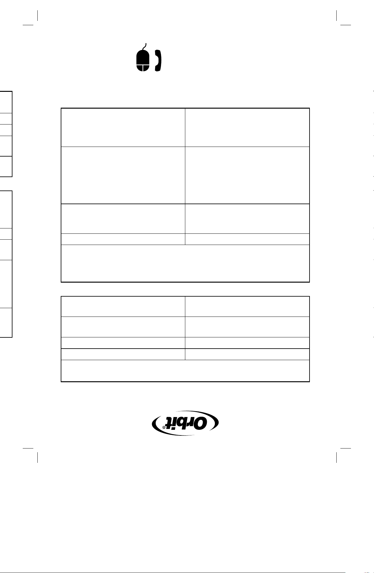
Manifold System leaks at connections
Check Solution
Connectionsareloose Retightenconnections
O-ringisoutofplace,damaged,
ormissing
Replaceo-ringinproperplace
Waterpressureexceeds80PSI
Installapressureregulator
upstreamofmanifold
The valve does not open electrically (but opens using the bleed screw)
and sprinkler timer is functioning
Check Solution
Individualsprinklerwire
pullsouteasily
UntwistwiresandfollowStep5in
“EasyWire”Connection
Bareindividualsprinklerwire
extendsbeyondprotective
membrane
Removewireandensurethebare
wireisnotshorterthan7/8"and
nomorethan1"inlength.Untwist
wiresandfollowStep5in“Easy
Wire”Connection
IndividualSprinklerwiresare
heldrmlyinplacebutarenot
contactingbarewire
Ensurethebaresprinklerwireis
notshorterthan7/8"andnomore
than1"inlength.
Solución de problemas
El sistema del tubo colector tiene fugas en las conexiones
Revise Solución
Lasconexionesestánsueltas Vuelvaaapretarlasconexiones
Lajuntatóricaestádañada,en
posiciónincorrectaonoestá
Pongalajuntatóricaen
sulugarnuevamente
Lapresióndeagua
superalos80PSI
Instaleunreguladordepresión
aguasarribadeltubocolector
La válvula no se abre eléctricamente (pero se abre utilizando el tornillo
de purga) y el temporizador del regador está funcionando
Revise Solución
Elconductordecadaregador
sesaleconfacilidad
Separelosconductoresy
procedaconelpaso5en
Conexión“EasyWire”.
Losconductorespelados
individualesdelregadorse
extiendenhastamásalláde
lamembranaprotectora
Retireelconductoryasegúrese
dequeelconductorpeladotenga
unalongitudmínimade2,2cm
ymáximade2,5cm.Separelos
conductoresyprocedaconelpaso
5enConexión“EasyWire”.
Losconductoresdecadaregador
estánrmesensulugarpero
notienencontactoconlos
conductorespelados
Asegúresedequeelconductor
peladodelregadortengauna
longitudmínimade2,2cmy
máximade2,5cm
Orbit
®
Irrigation Products Inc.
North Salt Lake, Utah 84054 USA
www.orbitonline.com
1-800-488-6156
CUSTOMER SERVICE
1-800-488 -6 156
www.orbitonline.com
CUSTOMER SERVICE
1-800-488 -6 156
www.orbitonline.com
conexión “easy Wire”
Nota:elsistema“EasyWire”sólosedebe
usarentemporizadoresderegadoresde24
voltiosconcircuitosClaseII.Todoelcableado
debecumplirconlasregulacioneslocales
vigentes.
1. Desconecteeltemporizadorde
regadoresdelaalimentacióneléctrica.
2. Paseelconductordelregador(use
conductordecalibre16a20)desdeel
temporizadorhastaelconjuntodeltubo
colector.
3. Retirede10,2a12,7cmdeaislante
externodelcabledelregador.
Advertencia:tengacuidadodenocortar
losconductoresenelinterior.
4. Retirede2,2a2,5cmdeaislantede
cadaconductor(Figura 6).
5. Inserteunconductordelaválvulayun
conductordecolordeltemporizador
enelempalmeplásticoydóblelospara
asegurarlosenél.Sedebeusarun
conductorparacadazonayelconductor
adicionalseusacomoconductorcomún
(paraidenticarlomásfácilmente,utilice
elconductorblancocomoelcomún).
Nota:elconductordebemantenerse
rmealjalarlosuavemente.Sisemueve,
retíreloyrepitaelpaso5(Figura 7).
6. Junteelsegundoconductordecada
válvulaconelconductorcomúnblanco
deltemporizadorydóblelosdentrodel
empalmeplástico(Figura 8).
7. Insertecadaempalmeplásticoenla
cavidadcorrespondientedentrodel
organizador“EasyWire”(Figura 9).
8. Desliceelorganizador“EasyWire”hacia
laabrazaderademontajeyfíjeloala
válvuladeltubocolector(Figura 10).
prueba
Advertencia:antesdecontinuar,asegúresedequelasunionesdecementohayan
alcanzadoeltiempodecuradorecomendado(varíadeacuerdoconelfabricante).
1. Asegúresedequelostornillosdepurgamanualdelasválvulasestén
completamentecerrados(apriételosconlamanogirandoenelsentidodelas
manecillasdelreloj).
2. Abralatuberíadesuministrodelregadoryrevisesihayfugaseneltubo
colectoroenlaválvula.Sihayfugas,utiliceunalicateparaltrosparaapretar
SUAVEMENTElasconexioneshastaquelafugasedetenga.NOapriete
demasiadolasconexiones.
3. GireelTornillodepurgamanualendireccióncontrariaalasmanecillasdelreloj
hastaquesalgaagua;déjelacorrerpor20segundosygíreloendireccióndelas
manecillasdelrelojparavolveraapretarlo.Repitaelprocedimientocontodaslas
válvulas.
4. Veriquequeeltemporizadordelregadorestéconectadoyqueelinterruptor
decircuitoestéencendido.Activemanualmentecadaestacióndesdeel
temporizadorparacomprobarlaconexióneléctricahacialaválvula.
Figura 8
Figura 9
Figura 10
Figura 6
Figura 7
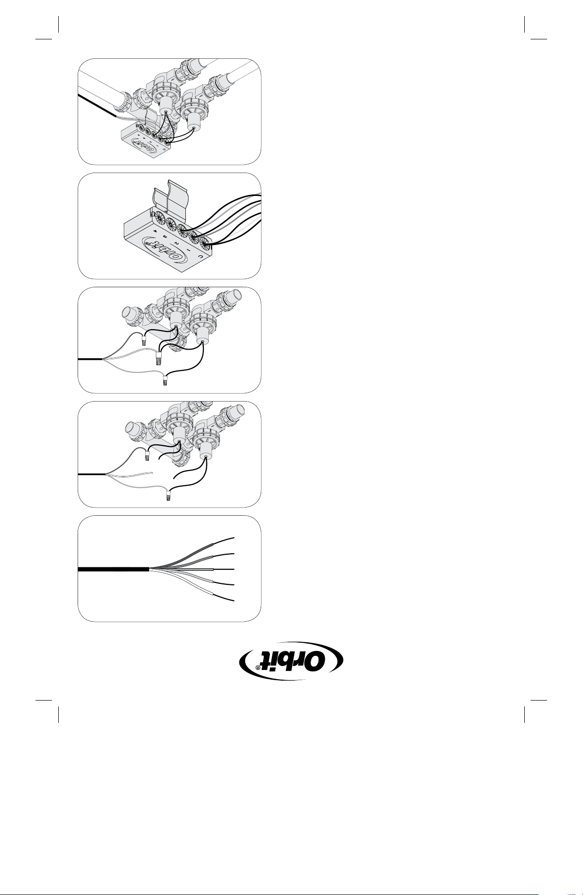
conexión “easy Wire”
Nota:elsistema“EasyWire”sólosedebe
usarentemporizadoresderegadoresde24
voltiosconcircuitosClaseII.Todoelcableado
debecumplirconlasregulacioneslocales
vigentes.
1. Desconecteeltemporizadorde
regadoresdelaalimentacióneléctrica.
2. Paseelconductordelregador(use
conductordecalibre16a20)desdeel
temporizadorhastaelconjuntodeltubo
colector.
3. Retirede10,2a12,7cmdeaislante
externodelcabledelregador.
Advertencia:tengacuidadodenocortar
losconductoresenelinterior.
4. Retirede2,2a2,5cmdeaislantede
cadaconductor(Figura 6).
5. Inserteunconductordelaválvulayun
conductordecolordeltemporizador
enelempalmeplásticoydóblelospara
asegurarlosenél.Sedebeusarun
conductorparacadazonayelconductor
adicionalseusacomoconductorcomún
(paraidenticarlomásfácilmente,utilice
elconductorblancocomoelcomún).
Nota:elconductordebemantenerse
rmealjalarlosuavemente.Sisemueve,
retíreloyrepitaelpaso5(Figura 7).
6. Junteelsegundoconductordecada
válvulaconelconductorcomúnblanco
deltemporizadorydóblelosdentrodel
empalmeplástico(Figura 8).
7. Insertecadaempalmeplásticoenla
cavidadcorrespondientedentrodel
organizador“EasyWire”(Figura 9).
8. Desliceelorganizador“EasyWire”hacia
laabrazaderademontajeyfíjeloala
válvuladeltubocolector(Figura 10).
prueba
Advertencia:antesdecontinuar,asegúresedequelasunionesdecementohayan
alcanzadoeltiempodecuradorecomendado(varíadeacuerdoconelfabricante).
1. Asegúresedequelostornillosdepurgamanualdelasválvulasestén
completamentecerrados(apriételosconlamanogirandoenelsentidodelas
manecillasdelreloj).
2. Abralatuberíadesuministrodelregadoryrevisesihayfugaseneltubo
colectoroenlaválvula.Sihayfugas,utiliceunalicateparaltrosparaapretar
SUAVEMENTElasconexioneshastaquelafugasedetenga.NOapriete
demasiadolasconexiones.
3. GireelTornillodepurgamanualendireccióncontrariaalasmanecillasdelreloj
hastaquesalgaagua;déjelacorrerpor20segundosygíreloendireccióndelas
manecillasdelrelojparavolveraapretarlo.Repitaelprocedimientocontodaslas
válvulas.
4. Veriquequeeltemporizadordelregadorestéconectadoyqueelinterruptor
decircuitoestéencendido.Activemanualmentecadaestacióndesdeel
temporizadorparacomprobarlaconexióneléctricahacialaválvula.
Figura 8
Figura 9
Figura 10
Figura 6
Figura 7
pautas importantes
• Advertencia:NOuseaditivosparatubosenlasroscas;usecintaaislante.
• Coloqueeltubocolectordemodoqueelaguaescurralejosdelacasa.
• Sinovaautilizaraguapotable,instaleunltroaguasarribadeltubocolector.
colocación de la válvula
1. Seleccioneunaubicaciónparaelsistemadeválvulasderegadores
conlossiguientescriterios:
• Accesoalatuberíadeagua.
• Accesoalcableentreelregadoryeltemporizador.
• Terrenoelevado:eviteáreasbajasdondeelaguasepuedaacumularen
lacajadeválvulas.
2. UseunacajadeválvulasOrbit
®
(noseincluye)paraprotegerelsistemadeválvulasde
regadores.
3. Cuandohayaseleccionadolaubicación,caveunagujeroenlatierradeuna
profundidadsucienteparaquecajadeválvulasquedeniveladayalrasconel
terreno.
Consejo:Orbit
®
recomiendacolocarentre2,5y4cmdegravabajolacajade
válvulasparaeldrenajedelagua.
instalación
1. Asegúresedeapretarconlamanotodos
losconectores.
Advertencia:NOutilicellaves,alicates
paraltrosniotrasherramientaspara
apretarlosconectores.
2. Compruebequelaechadedirección
delujo(ubicadaenelcuerpodela
válvula)apuntehaciaelladoopuestoal
tubocolector.
3. Conecteeltubocolectoralatubería
principaldePVCconcementoPVC.
• SieltubodePVCesde¾",
conéctelodirectamentealAdaptador
giratorio(C)(Figura 1).
• SieltubodePVCesde1",conéctelo
aladaptadorgiratoriodePVC
medianteunacoplador(H)(Figura 2).
• Sieltuboesmásgrande,utilice
reductores(noincluidos).
4. Conecteelsistemadeválvulasde
regadoresalastuberíasprincipales
delregador(lastuberíasdelregador
queestándirectamentedespuésdela
válvula).
• SieltubodePVCesde¾",conéctelo
directamentealAdaptadorde
transición(F)(Figura 3).
• SieltubodePVCesde1",conéctelo
aladaptadordetransiciónmediante
unacoplador(H)(Figura 4).
• Siesuntubodepolietilenode¾"o
1",utiliceunadaptadorde
polietileno(incluidoenlosmodelos
91207/91206)yasegúreloconuna
abrazaderaparatubería(Figura 5).
Figura 1
Figura 2
Figura 3
Figura 4
Figura 5
pautas importantes
• Advertencia:NOuseaditivosparatubosenlasroscas;usecintaaislante.
• Coloqueeltubocolectordemodoqueelaguaescurralejosdelacasa.
• Sinovaautilizaraguapotable,instaleunltroaguasarribadeltubocolector.
colocación de la válvula
1. Seleccioneunaubicaciónparaelsistemadeválvulasderegadores
conlossiguientescriterios:
• Accesoalatuberíadeagua.
• Accesoalcableentreelregadoryeltemporizador.
• Terrenoelevado:eviteáreasbajasdondeelaguasepuedaacumularen
lacajadeválvulas.
2. UseunacajadeválvulasOrbit
®
(noseincluye)paraprotegerelsistemadeválvulasde
regadores.
3. Cuandohayaseleccionadolaubicación,caveunagujeroenlatierradeuna
profundidadsucienteparaquecajadeválvulasquedeniveladayalrasconel
terreno.
Consejo:Orbit
®
recomiendacolocarentre2,5y4cmdegravabajolacajade
válvulasparaeldrenajedelagua.
instalación
1. Asegúresedeapretarconlamanotodos
losconectores.
Advertencia:NOutilicellaves,alicates
paraltrosniotrasherramientaspara
apretarlosconectores.
2. Compruebequelaechadedirección
delujo(ubicadaenelcuerpodela
válvula)apuntehaciaelladoopuestoal
tubocolector.
3. Conecteeltubocolectoralatubería
principaldePVCconcementoPVC.
• SieltubodePVCesde¾",
conéctelodirectamentealAdaptador
giratorio(C)(Figura 1).
• SieltubodePVCesde1",conéctelo
aladaptadorgiratoriodePVC
medianteunacoplador(H)(Figura 2).
• Sieltuboesmásgrande,utilice
reductores(noincluidos).
4. Conecteelsistemadeválvulasde
regadoresalastuberíasprincipales
delregador(lastuberíasdelregador
queestándirectamentedespuésdela
válvula).
• SieltubodePVCesde¾",conéctelo
directamentealAdaptadorde
transición(F)(Figura 3).
• SieltubodePVCesde1",conéctelo
aladaptadordetransiciónmediante
unacoplador(H)(Figura 4).
• Siesuntubodepolietilenode¾"o
1",utiliceunadaptadorde
polietileno(incluidoenlosmodelos
91207/91206)yasegúreloconuna
abrazaderaparatubería(Figura 5).
Tapa de extremo
1Tubo colector de 1, 2 ó 3 puertos
Adaptador giratorio de PVC
(se conecta a la tubería principal
del regador)
Adaptadores giratorios de 1"
Válvula roscada hembra de 1"
Adaptador de transición de PVC
Adaptador de polietileno de ¾" o
1" (no se incluye)
Acoplador
A
A
F
E
G
F
H
D
G
H
B
B
C
C
E
D
D
SiStema de VálVulaS
de reGadoreS
manual de
inStruccioneS