v
SPRINKLER VALVE SYSTEM
INSTRUCTION MANUAL
Important Guidelines
• Warning: DO NOT use pipe dope on threads, use thread seal tape
• Place the manifold so that water drains away from the house
• If not using culinary water, install a filter upstream of the manifold
Valve Placement
1. Select a location for the Sprinkler Valve System
with the following criteria:
• Accessible to water supply line
• Accessible to sprinkler wire from timer
• Elevated ground—avoid low areas where water will accumulate
in valve box
2. Use a valve box (not included) to protect the sprinkler valve system
3. Once a location is selected, dig a hole in the ground deep enough so
the top of the valve box will be flat and level with the surface.
Tip: Orbit
®
recommends using an Orbit
®
valve box base to create a
stable platform for your valve system. Place 1" to 1 1/2" of gravel
below the valve box for drainage
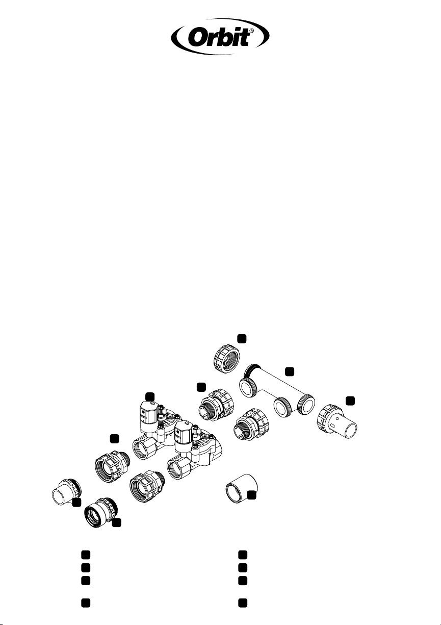
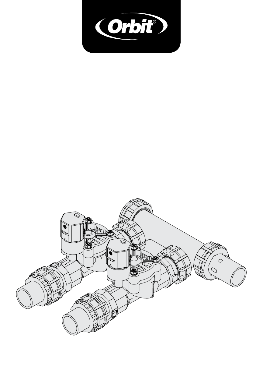
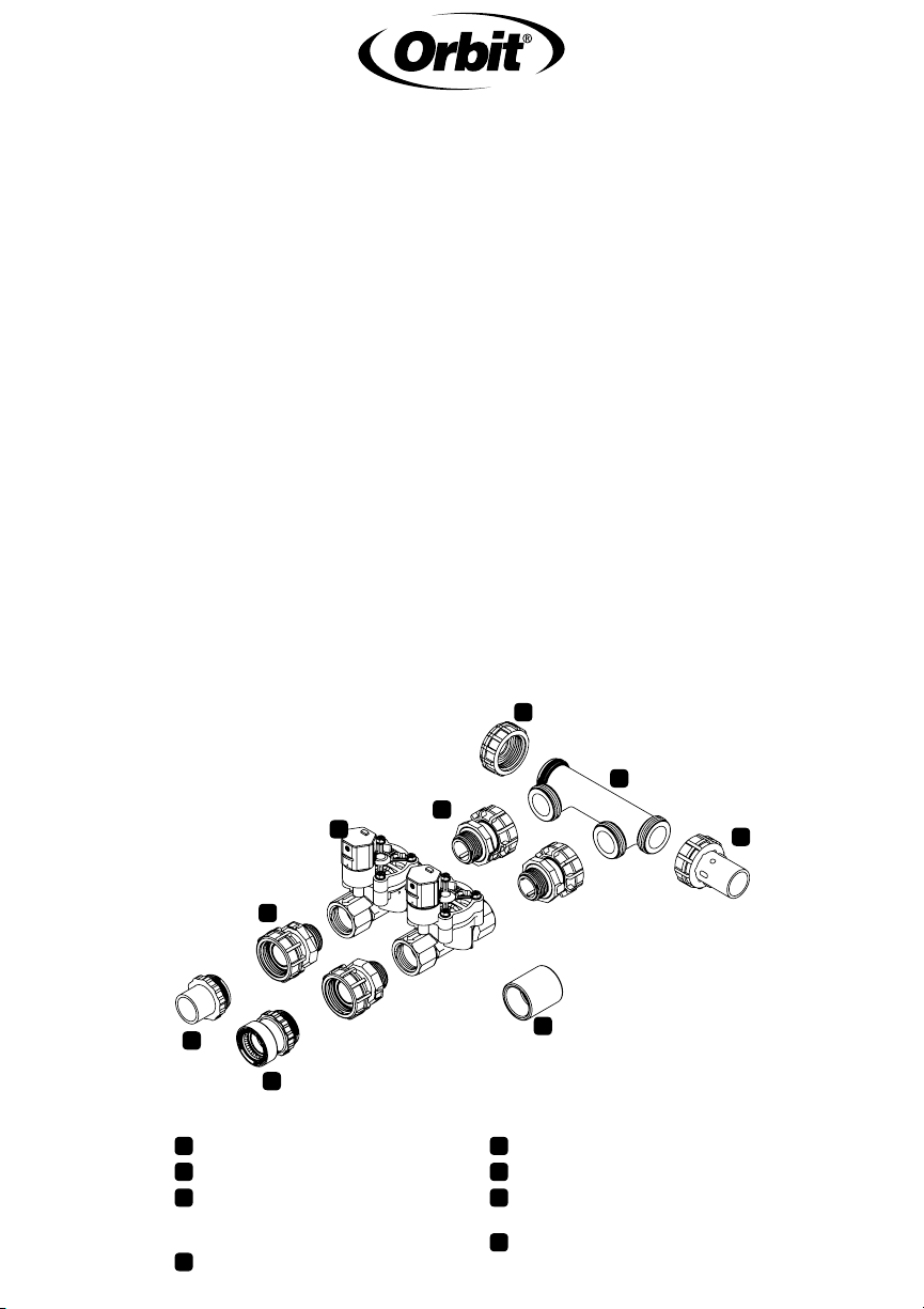
End Cap
1, 2, or 3 Port Manifold
PVC Swivel Adapter
(connects to sprinkler mainline)
1" Swivel Adapters
1" Female Thread Valve
PVC Transition Adapter
¾" or 1" Poly Adapter
(not included)
Coupler
A
A
F
E
G
F
HD
G
H
B
B
C
C
E
D
D
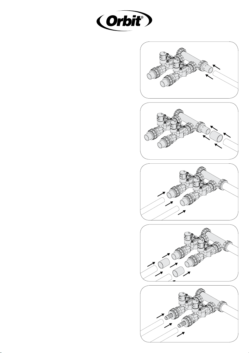
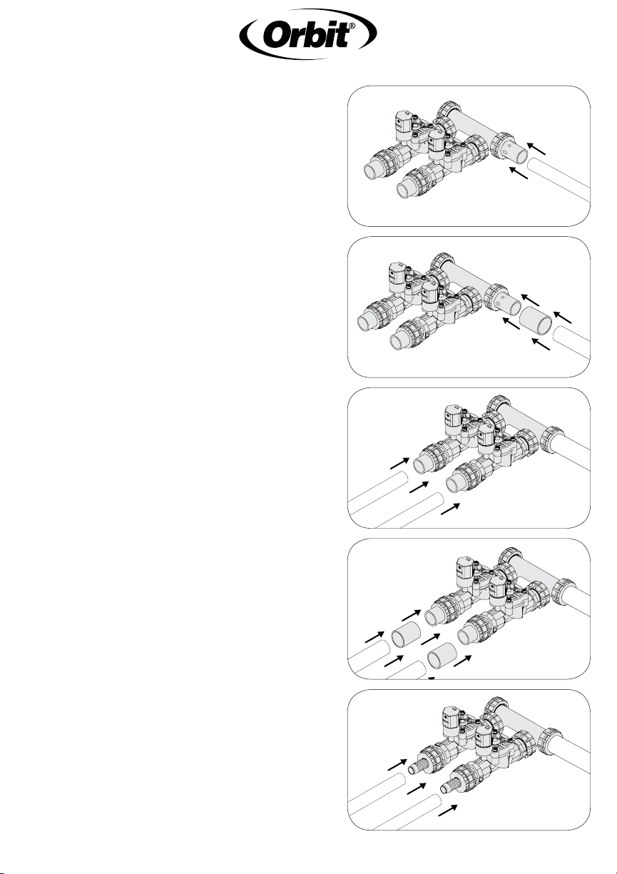
Installation
1. Check each fitting connection to
make sure it is hand-tight.
Warning: DO NOT use wrenches,
channel locks, or other tools to
tighten fittings
2. Check to make sure that the flow
direction arrow (located on the
body of the valve) is pointed away
from the manifold
3. Connect the manifold to PVC
mainline using PVC cement
• For ¾" PVC pipe, connect
directly to Swivel Adapter (C)
(Figure 1)
• For 1" PVC pipe, use a Coupler
(H) between PVC Swivel Adapter
and pipe (Figure 2)
• For larger size mainline,
purchase and install reducer
4. Connect your Sprinkler Valve
System to your sprinkler header
lines (sprinkler lines directly after
the valve)
• For ¾" PVC pipe, connect
directly to Transition Adapter (F)
(Figure 3)
• For 1" PVC pipe, use Coupler
(H) between Transition Adapter
and pipe (Figure 4)
• For ¾" or 1" Poly Pipe, use
Poly Adapter (included in
91207/91206) and secure with
tubing clamp (Figure 5)
Figure 1
Figure 2
Figure 3
Figure 4
Figure 5
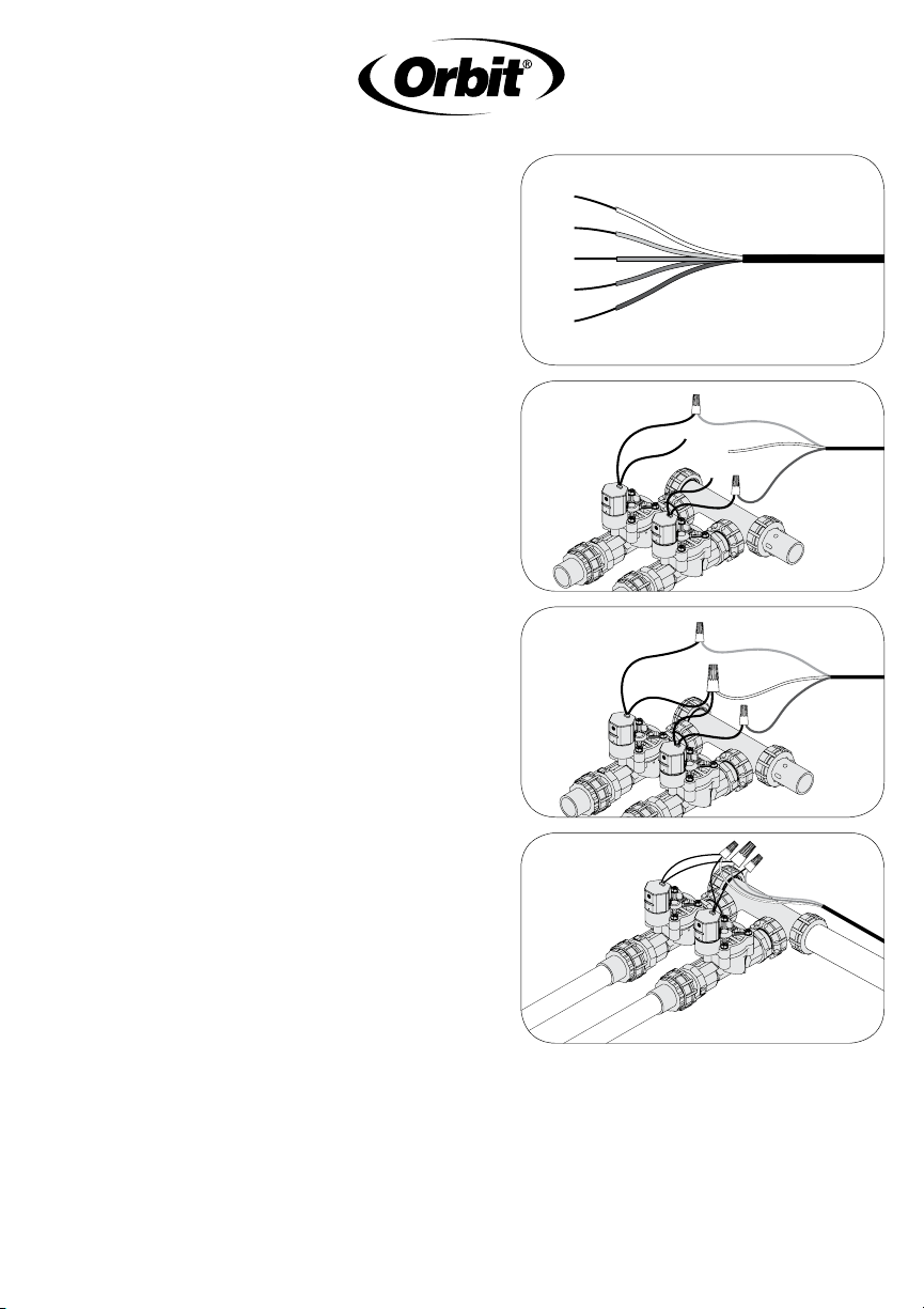
“Speed-Seal
™
” Connection
Note: The “Speed-Seal” System should
only be used on 24-Volt sprinkler timers
with Class II circuits. All wiring must
conform to applicable local codes.
1. Disconnect power to your sprinkler
timer
2. Run sprinkler wire (use 16ga–20ga
wire) from your timer to the
manifold assembly
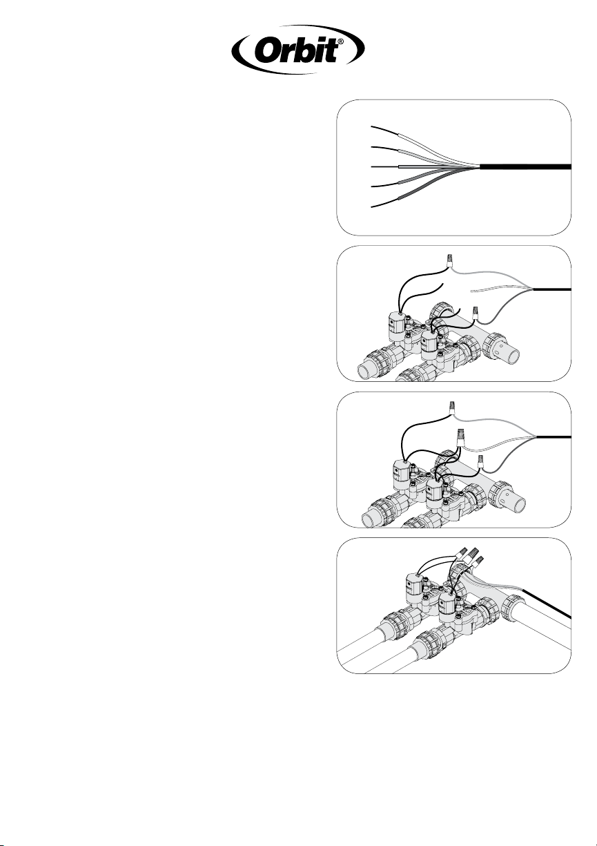
3. Remove 4"–5" of the outer
insulation of the sprinkler wire
Warning: Avoid cutting into the
wires inside
4. Remove 7/8"–1" of insulation from
each individual wire (Figure 6)
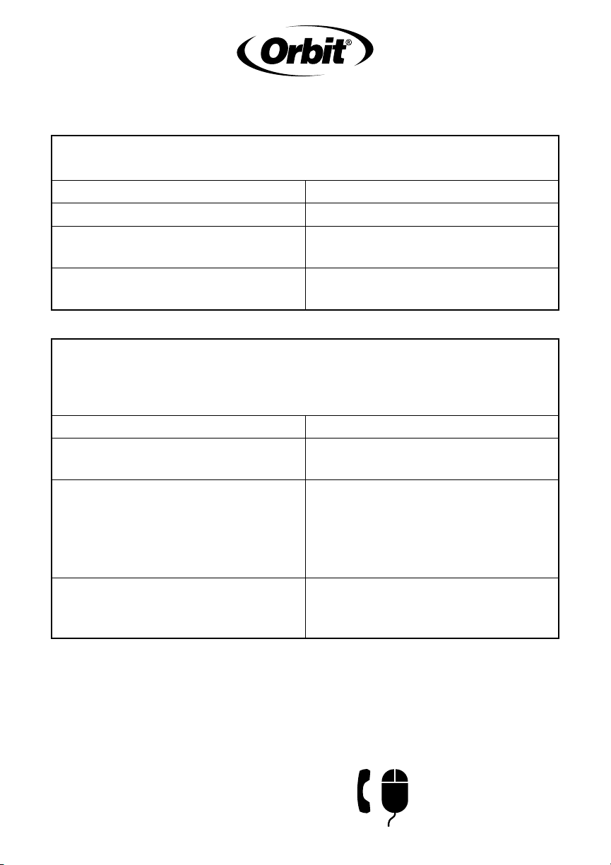
5. Insert one wire from the valve and a
colored wire from the timer into the
Speed-Seal connector nut. One wire
should be used for each zone with
an additional wire to be used for a
common (for ease of identification,
use the white wire as the common).
Note: The wire should hold firm
when lightly pulled. If the wire
moves freely, remove the wire and
repeat Step 5. (Figure 7)
6. Take the second wire from each
valve and the white common wire
from the timer and twist them into
the wire nut provided Speed-Seal
connector nuts.
Figure 8
Figure 9
Figure 6
Figure 7

Testing
Warning: Before proceeding, make sure cemented joints have reached the
recommended curing time (varies according to manufacturer).
1. Ensure the solenoids on the valves are fully closed (turn clockwise
until hand-tight).
2. Turn on sprinkler supply line and check manifold and valve for leaks. If
any leak occurs, LIGHTLY tighten connections with channel locks until
the leak stops. DO NOT over-tighten swivels.
3. Turn solenoid counterclockwise 1/4 turn until water flows out—run for
20 seconds and turn clockwise to retighten. Repeat with all valves.
4. Check that the sprinkler timer is plugged in and/or the circuit breaker
is on. Run each station manually from the timer to verify electrical
connection to the valve.
Manifold System leaks at connections
Check Solution
Connections are loose Retighten connections
O-ring is out of place, damaged,
or missing
Replace o-ring in proper place
Water pressure exceeds 80 PSI
Install a pressure regulator
upstream of manifold
The valve does not open electrically (but opens using the bleed screw)
and sprinkler timer is functioning
Check Solution
Individual sprinkler wire
pulls out easily
Untwist wires and follow Step 5 in
“Speed-Seal” Connection
Bare individual sprinkler wire
extends beyond protective
membrane
Remove wire and ensure the bare
wire is not shorter than 7/8" and
no more than 1" in length. Untwist
wires and follow Step 5 in “Speed-
Seal” Connection
Individual Sprinkler wires are
held firmly in place but are not
contacting bare wire
Ensure the bare sprinkler wire is
not shorter than 7/8" and no more
than 1" in length.
Orbit
®
Irrigation Products Inc.
North Salt Lake, Utah 84054 USA
www.orbitonline.com
1-800-488-6156
PN 57250-24 rD
Troubleshooting
CUSTOMER SERVICE
1-800-488-6156
www.orbitonline.com
SISTEMA DE VÁLVULAS
DE REGADORES
MANUAL DE
INSTRUCCIONES
Pautas importantes
• Advertencia: NO use aditivos para tubos en las roscas; use cinta aislante.
• Coloque el tubo colector de modo que el agua escurra lejos de la casa.
• Si no va a utilizar agua potable, instale un filtro aguas arriba del tubo colector.
Colocación de la válvula
1. Seleccione una ubicación para el sistema de válvulas de regadores
con los siguientes criterios:
• Acceso a la tubería de agua.
• Acceso al cable entre el regador y el temporizador.
• Terreno elevado: evite áreas bajas donde el agua se pueda acumular en
la caja de válvulas.
2. Use una caja de válvulas Orbit
®
(no se incluye) para proteger el sistema de válvulas de
regadores.
3. Cuando haya seleccionado la ubicación, cave un agujero en la tierra de una
profundidad suficiente para que caja de válvulas quede nivelada y al ras con el
terreno.
Consejo: Orbit recomienda utilizar una base de la caja de válvulas Orbit para
crear una plataforma estable para su sistema de válvulas. Coloque entre 2,54 a
3,81 cm de gravilla bajo la caja de válvulas para el drenaje del agua.
Tapa de extremo
1Tubo colector de 1, 2 ó 3 puertos
Adaptador giratorio de PVC
(se conecta a la tubería principal
del regador)
Adaptadores giratorios de 1"
Válvula roscada hembra de 1"
Adaptador de transición de PVC
Adaptador de polietileno de ¾" o
1" (no se incluye)
Acoplador
A
A
F
E
G
F
H
D
G
H
B
B
C
C
E
D
D
Instalación
1. Asegúrese de apretar con la mano todos
los conectores.
Advertencia: NO utilice llaves, alicates
para filtros ni otras herramientas para
apretar los conectores.
2. Compruebe que la flecha de dirección
del flujo (ubicada en el cuerpo de la
válvula) apunte hacia el lado opuesto al
tubo colector.
3. Conecte el tubo colector a la tubería
principal de PVC con cemento PVC.
• Si el tubo de PVC es de ¾",
conéctelo directamente al Adaptador
giratorio (C) (Figura 1).
• Si el tubo de PVC es de 1", conéctelo
al adaptador giratorio de PVC
mediante un acoplador (H) (Figura 2).
• Si el tubo es más grande, utilice
reductores (no incluidos).
4. Conecte el sistema de válvulas de
regadores a las tuberías principales
del regador (las tuberías del regador
que están directamente después de la
válvula).
• Si el tubo de PVC es de ¾", conéctelo
directamente al Adaptador de
transición (F) (Figura 3).
• Si el tubo de PVC es de 1", conéctelo
al adaptador de transición mediante
un acoplador (H) (Figura 4).
• Si es un tubo de polietileno de ¾" o
1", utilice un adaptador de
polietileno (incluido en los modelos
91207/91206) y asegúrelo con una
abrazadera para tubería (Figura 5).
Figura 1
Figura 2
Figura 3
Figura 4
Figura 5
Conexión “Speed-Seal™”
Nota: el sistema “Speed-Seal” sólo se debe
usar en temporizadores de regadores de 24
voltios con circuitos Clase II. Todo el cableado
debe cumplir con las regulaciones locales
vigentes.
1. Desconecte el temporizador de
regadores de la alimentación eléctrica.
2. Pase el conductor del regador (use
conductor de calibre 16 a 20) desde el
temporizador hasta el conjunto del tubo
colector.
3. Retire de 10,2 a 12,7 cm de aislante
externo del cable del regador.
Advertencia: tenga cuidado de no cortar
los conductores en el interior.
4. Retire de 2,2 a 2,5 cm de aislante de
cada conductor (Figura 6).
5. 5. Inserte un cable de la válvula y un
cable de color del temporizador en la
tuerca del conector Speed-Seal. Se
debe utilizar un cable para cada zona
con un cable adicional que se debe usar
como cable común (para facilitar la
identificación, use el cable blanco como
el común).
Nota: El cable debe permanecer firme
cuando lo hale suavemente. Si el cable
se mueve libremente, retírelo y repita el
Paso 5. (Figura 7)
6. Tome el segundo cable de cada válvula y
el cable blanco común del temporizador
y tuérzalos en el empalme para cables
que se proporciona con las tuercas del conector Speed-Seal.
Figura 8
Figura 9
Figura 6
Figura 7

. Prueba
Advertencia: antes de continuar, asegúrese de que las uniones de cemento hayan
alcanzado el tiempo de curado recomendado (varía de acuerdo con el fabricante).
1. Asegúrese de que los selenoides en las válvulas estén completamente cerrados
(apriételos con la mano girándolos en dirección de las manecillas del reloj).
2. Abra la tubería de suministro del regador y revise si hay fugas en el tubo
colector o en la válvula. Si hay fugas, utilice un alicate para filtros para apretar
SUAVEMENTE las conexiones hasta que la fuga se detenga. NO apriete
demasiado las conexiones.
3. Gire los solenoides un cuarto de vuelta en dirección de las manecillas del reloj
hasta que el agua fluya; déjela correr por 20 segundos y gírelo en dirección de las
manecillas del reloj para volver a apretarlo. Repita el procedimiento con todas las
válvulas.
4. Verifique que el temporizador del regador esté conectado y que el interruptor
de circuito esté encendido. Active manualmente cada estación desde el
temporizador para comprobar la conexión eléctrica hacia la válvula.
Solución de problemas
El sistema del tubo colector tiene fugas en las conexiones
Revise Solución
Las conexiones están sueltas Vuelva a apretar las conexiones
La junta tórica está dañada, en
posición incorrecta o no está
Ponga la junta tórica en
su lugar nuevamente
La presión de agua
supera los 80 PSI
Instale un regulador de presión
aguas arriba del tubo colector
La válvula no se abre eléctricamente (pero se abre utilizando el tornillo
de purga) y el temporizador del regador está funcionando
Revise Solución
El conductor de cada regador
se sale con facilidad
Separe los conductores y
proceda con el paso 5 en
Conexión “Speed-Seal”.
Los conductores pelados
individuales del regador se
extienden hasta más allá de
la membrana protectora
Retire el conductor y asegúrese
de que el conductor pelado tenga
una longitud mínima de 2,2 cm
y máxima de 2,5 cm. Separe los
conductores y proceda con el paso
5 en Conexión “Speed-Seal”.
Los conductores de cada regador
están firmes en su lugar pero
no tienen contacto con los
conductores pelados
Asegúrese de que el conductor
pelado del regador tenga una
longitud mínima de 2,2 cm y
máxima de 2,5 cm
Orbit
®
Irrigation Products Inc.
North Salt Lake, Utah 84054 USA
www.orbitonline.com
1-800-488-6156
CUSTOMER SERVICE
1-800-488-6156
www.orbitonline.com