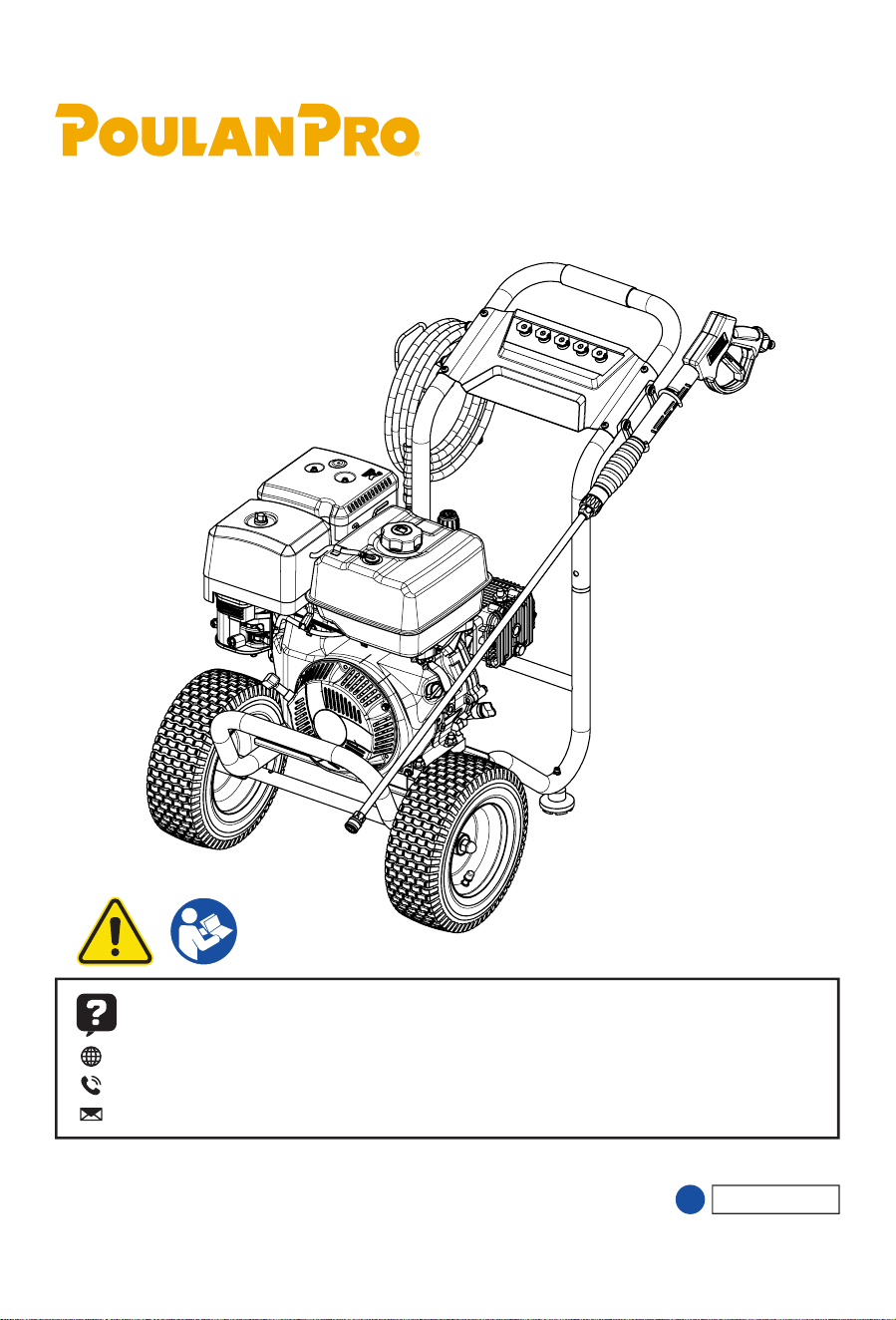
OPERATOR’S MANUAL
MODEL:PPW4400
4400 PSI Pressure Washer
Vol. 2025-04
EN
Have product questions or need technical support?
Contact Us:
Website: www.poulanpro.com
Toll free: 1-888-676-7909 Mon-Fri 8-4 CST
Email: support@poulanpro-power.us
Manufactured under license from Husqvarna AB
Poulan Pro is a registered Trademark of Husqvarna AB
Imported by Novus Performance Products.
W225N16708 Cedar Parl Ct. Jackson, WI

PRESSURE WASHER
CONTENTS
-2-
CONTENTS
Specifications
Introduction / Safety Definitions
Important Safety Instructions
Know Your Product
Assembly
Operation
Maintenance
Transportation and Storage
Troubleshooting
Basic Service Parts List
Warranty Statement
3
4
5
10
12
16
21
26
27
28
29
SPECIFICATIONS
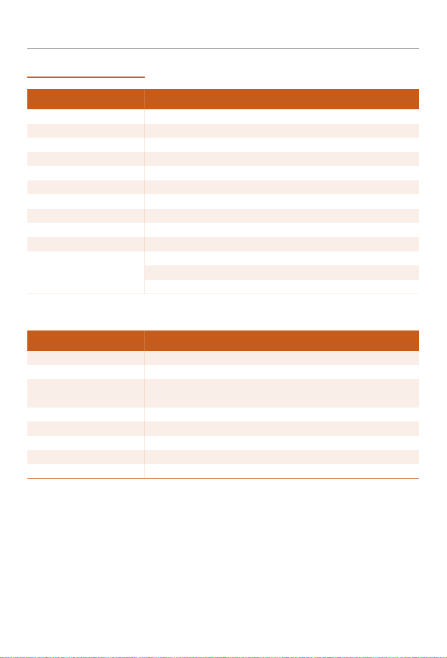
SPECIFICATIONS
Model
PPW4400
Engine Displacement
Engine Type
Fuel Type
Fuel Capacity
Spark Plug
Spark Plug Gap
Oil Type
Oil Capacity
420 cc
4-Stroke, Air Cooled, Overhead Valve (OHV)
Fresh, clean regular unleaded gasoline with a minimum octane
rating of 87 and ethanol content of no more than 10% by volume.
1.2 gal.(4.6 L)
F7RTC Torch / BPR7ES NGK
0.030 in. (0.7-0.8 mm)
SAE 10W-30
37 fl oz. (1.1 L)
-3-
PRESSURE WASHER
Engine Model
WM190F/P
Engine
Max Pressure
Max Flow
Pump Type
Pump Oil Type
Pump Oil Capacity
Min Water Supply Flow Rate
Min Water Supply Pressure
Max Inlet Water Temperature
Spray Nozzles
Weight
4400 PSI
6.34 GPM (24 L/min)
Triplex Plunger Pump
SAE 15W-40
12 fl oz. (350 ml)
6.3 GPM (24 L/min)
30 PSI(2.07 bar)
104° F (40° C)
0°, 15°, 25°, 40°, Soap - Quick Connect
139 lbs (63 kg)
Length: 50.39 in. (128 cm)
Width: 24.40 in. (62 cm)
Height: 32.1 in.(81.5 cm)
Dimensions
INTRODUCTION / SAFETY DEFINITIONS
INTRODUCTION
-4-
PRESSURE WASHER
Congratulations on your purchase of a PoulanPro®
branded product. This model is the result of our
vast experience in the production of high- quality,
cost-effective equipment.
It represents the high degree of reliability and
innovation that PoulanPro® has dedicated itself
to.
This manual will give you an understanding of the
assembly, operation and basic maintenance of
this unit. If you have any questions concerning the
operation or maintenance, please contact us at
support@poulanpro-power.us or 888-676-7909.
We want you to continue to use and be satisfied
with your product for years to come, therefore
please fully familiarize yourself, and others who
plan on operating the product, with the proper
safety and operation procedures before each use
We continually seeks advancements in product
design and quality. Therefore, while this manual
contains the most current product information
available at the time of printing, there may be
minor discrepancies between your product and
this manual.
When contacting us about parts and/or service,
you will need to supply the complete product and
serial numbers of your unit.
SAFETY DEFINITIONS
The purpose of safety symbols is to attract your
attention to possible dangers. The safety symbols,
and their explanations, deserve your careful
attention and understanding. The safety warnings
do not by themselves eliminate any danger. The
instructions or warnings they give are not
substitutes for proper accident prevention
measures.
DANGER indicates a hazardous situation
which, if not avoided, will result in death or
serious injury.
DANGER
WARNING indicates a hazardous situation
which, if not avoided, could result in death or
serious injury.
WARNING
CAUTION indicates a hazardous situation
which, if not avoided, may result in minor or
moderate injury.
CAUTION
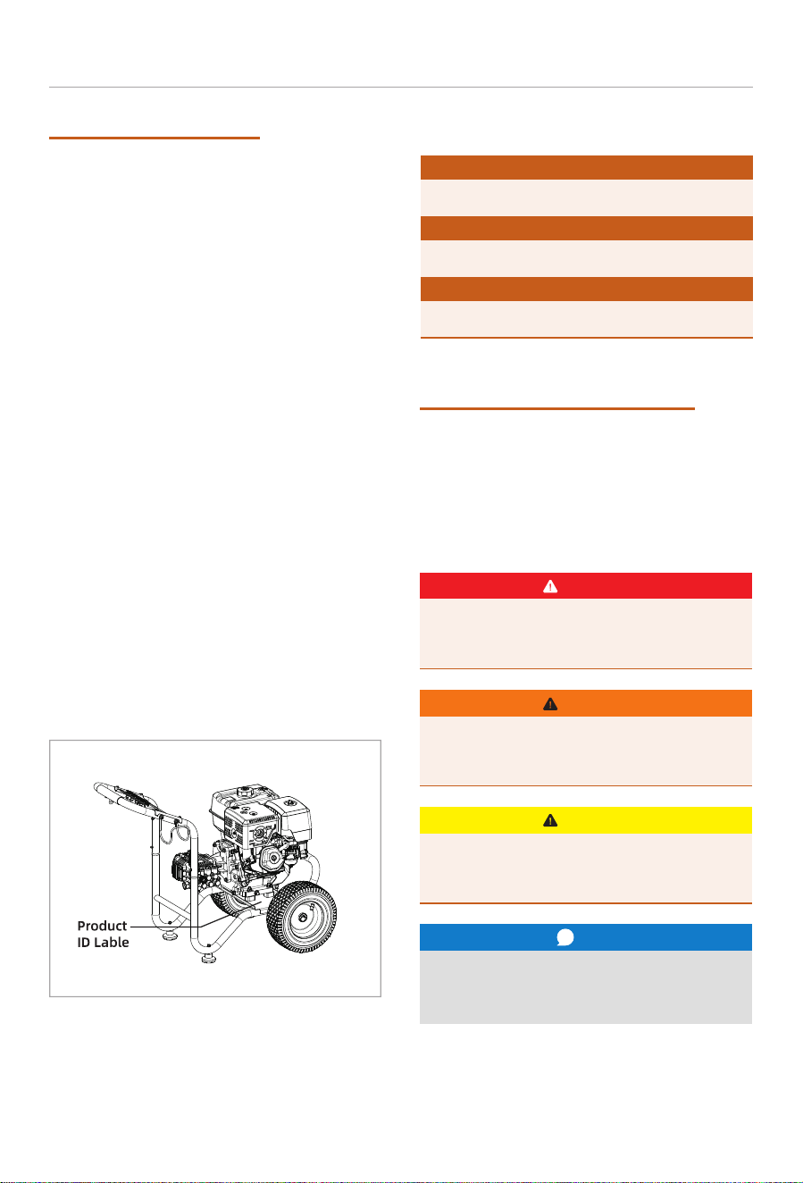
PRODUCT NUMBER
SERIAL NUMBER
DATE OF PURCHASE
Record the following information to obtain service
or warranty assistance
NOTICE
...
NOTlCE indicates information considered
important, but not hazard-related (e.g.,
messages relating to property damage).
IMPORTANT SAFETY INSTRUCTIONS
IMPORTANT SAFETY INSTRUCTIONS
-5-
DANGER
Engine exhaust contains carbon monoxide, a
colorless, odorless, poisonous gas. Breathing
carbon monoxide can headaches, nausea,
dizziness, drowsiness, confusion, fainting or
death. If you start to feel dizzy or weak, leave
the area immediately, get fresh air and Seek
Medical Treatment.
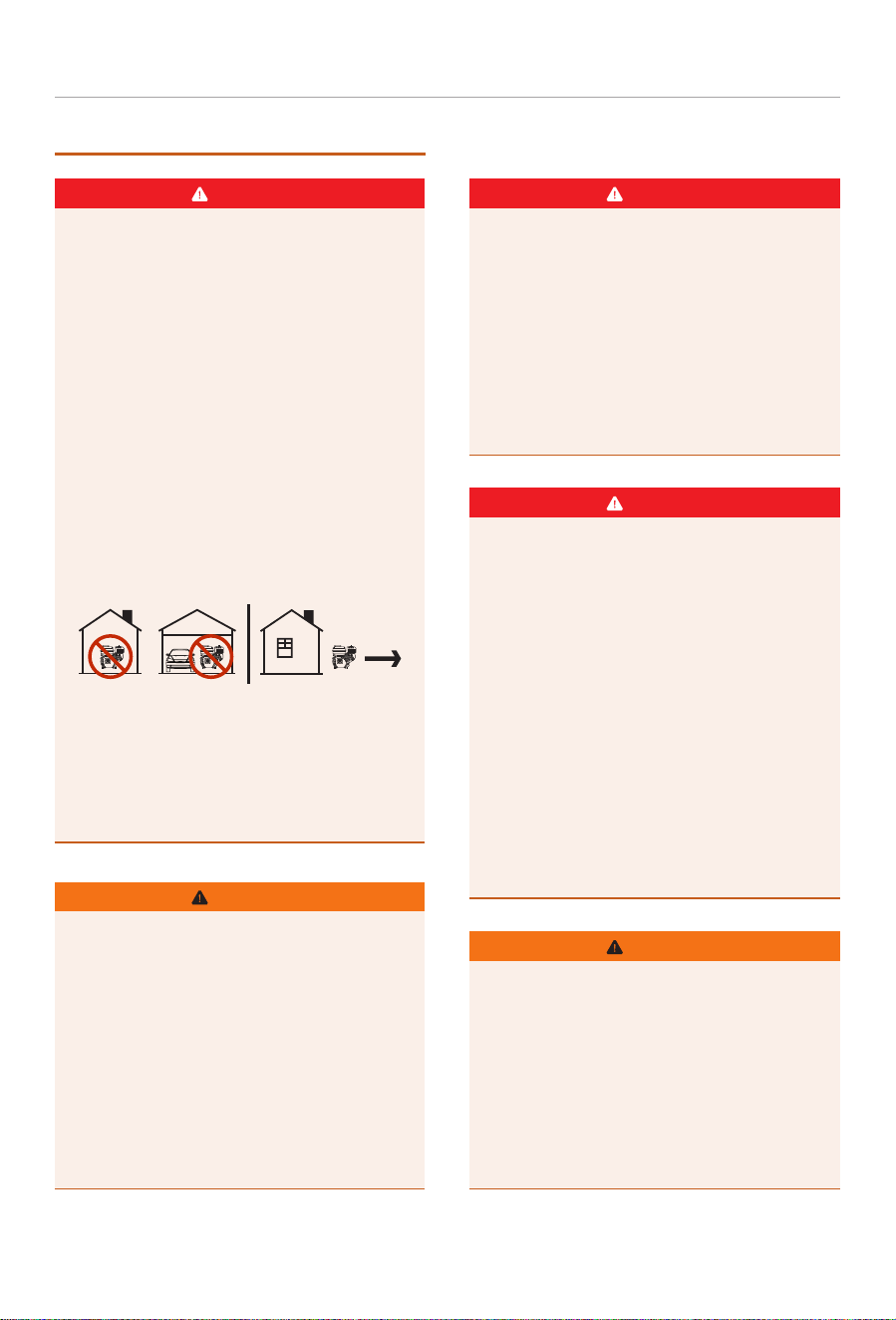
ALWAYS OPERATE EQUIPMENT OUTDOORS
ONLY, IN A WELL-VENTILATED AREA.
Using an engine indoors CAN KILL YOU IN
MINUTES. Engine exhaust contains carbon
monoxide. This is a poison you cannot see or
smell. Never start or operate gasoline
powered equipment inside any building,
including garages, basements, crawlspaces,
sheds or other partially enclosed or confined
areas.
Always use equipment Outside Only.
DO NOT allow exhaust fumes to enter a
confined area through windows, doors, vents
or other openings while operating the
product.
Risk of eye injury. Spray could splash back or
propel objects, resulting in serious injury.
Always wear vented safety goggles when
using or near this product. Safety glasses do
not provide full protection.
Always wear protective clothing sus as long-
sleeved shirts, long pants and closed toe
shoes when operating the pressure washer.
WARNING
PRESSURE WASHER
Before operating your machine, carefully
read and understand all safety, controls
and operating instructions in this Operator’s
Manual. Save these instructions. Refer to
them frequently and use them to instruct
others who may use this product.
DO NOT allow untrained individuals or
children to operate this equipment.
Failure to follow these instructions could
result in property damage, serious personal
injury or death.
WARNING
DANGER
Risk of injection or injury. High pressure jets
can be dangerous if subject to misuse.
DO NOT direct discharge stream at persons,
animals, electrical devices, or the machine
itself.
ALWAYS point spray gun in safe direction.
Every time you stop the engine, squeeze
trigger of spray gun to relieve any trapped
pressure.
DANGER
Keep Clear of spray nozzle.
DO NOT point the spray wand at a person,
animal or yourself.
Always wear safety glasses or goggles and
protective equipment (hearing protection,
gloves, rubber boots, protective clothing)
when operating or performing maintenance.
NEVER put hand or fingers over the spray tip
while operating the unit.
NEVER try to stop or deflect leaks with any
body part.
ALWAYS engage the trigger gun lockout
when spraying is stopped even if only for a
few moments.

Risk of electrocution. Contact with electrical
power source can cause electric shock or
burn.
Never spray near a power source or electrical
outlet.
WARNING
IMPORTANT SAFETY INSTRUCTIONS
-6-
Always Operate equipment with guards in
place.
Rotating parts can entangle hands, feet, hair,
clothing and/or accessories. Amputation or
severe laceration can result.
Keep hands and feet away from rotating
parts.
Tie up long hair and remove jewelry.
DO NOT wear loose-fitting clothing, dangling
drawstrings or items that could become
caught.
WARNING
Before performing any service to the unit:
The engine switch must be in the OFF
position and the engine completely stopped.
Allow the engine to cool down, remove and
ground the spark plug wire.
WARNING
WARNING
Running engines produce heat. Severe
burns can occur on contact. Combustible
material can catch fire on contact.
DO NOT touch hot surfaces.
Avoid contact with hot exhaust gases. Allow
equipment to cool before touching.
When operating maintain at least 3 ft. (91.4
cm) of clearance on all sides to ensure
adequate cooling.
Maintain at least 5 ft. (1.5 m) of clearance
from combustible materials.
PRESSURE WASHER
Use of a pressure washer can create wet
slippery surfaces causing loose footing and
falls.
Operate the pressure washer on a level
surface.
Always grasp the spray gun with two hands
to reduce kickback and potential loss of
footing.
Ensure there is proper drainage to disperse
the water.
WARNING
The pressure washer should have a minimum
of 5 feet clearance on all sides of buildings or
other equipment during operation.
Always operate the unit on level ground.
DO NOT attempt to start or run a damaged
unit
Do not operate this unit when you are tired,
ill, or under the influence of alcohol, drugs,
or medication.
Always inspect the unit before each use for
loose fasteners, fuel leaks, etc. Replace
damaged parts.
Maintain the equipment per maintenance
instructions located in this Operator’s
Manual.
When transporting the unit, always check
that the fuel valve is in the OFF position and
fuel cap is securely in place.
WARNING

Rapid retraction of the recoil cord will pull
hand and arm towards the engine faster
than you can let go. Broken bones, fractures,
bruises or sprains could result. Unintentional
startups can result in entanglement,
traumatic amputation or laceration.
When starting the engine, pull the recoil cord
slowly until resistance is felt and then pull
rapidly to avoid kickback.
WARNING
-7-
IMPORTANT SAFETY INSTRUCTIONS
PRESSURE WASHER
Never spray flammable liquids
Never use flammable or corrosive detergents
in the pressure washers soap tank.
Never use pressure washer in areas
containing combustible dust, liquids or vapor.
WARNING
NOTICE
...
Water under high pressure can damage
surfaces.
Always: test first on a small inconspicuous
area to understand if damage may occur.
Painted surfaces are very suspect to
damage.
Never: Point the spray nozzle at persons,
animals, glass surfaces or electrical
components.
NOTICE
...
Only use Cold water.
Never Let the pump run dry. Be sure the
water supply is turned on before operating
the unit.
Never let water in the pump freeze. Freezing
will cause internal pump damage and can
void your warranty.
Operate only on level surfaces.
Misuse of pressure washers is dangerous.
The gun should not be aimed at people, live
equipment, or the machine itself.
The resulting high-pressure water stream can
cut through the skin and underlying tissues,
never pull the trigger or aim the gun at
other people, animals, plants, or fragile
objects such as glass, even if the engine has
stopped.
Do not leave the gun unattended while the
equipment is running.
Make sure the gun, nozzles, and accessories
are properly connected.
Never attempt to repair high-pressure water
hose, be sure to replace them.
Never attempt to repair a leak with sealant
and always replace an O-ring or seal.
Never attempt to connect or disconnect
hoses from the pump or gun while the
system is pressurized.
Be sure to release the water pressure in the
appliance every time you stop the engine.
WARNING

-8-
IMPORTANT SAFETY INSTRUCTIONS
DO NOT light or smoke cigarettes while
handling gasoline.
Always stop the engine and allow it to cool
for a minimum of five minutes before
refueling.
Never pump gasoline directly into the
products fuel tank at the gas station.
Always fill or drain gasoline outdoors in a
well-ventilated area.
Always loosen fuel cap slowly to release any
vapor pressure and to keep fuel from
escaping around the fuel cap.
Always replace and tighten the fuel cap
securely after fueling.
Never remove the fuel cap or add fuel while
the engine is running or when the engine is
hot.
DO NOT overfill the gasoline tank.
DO NOT tip the product allowing fuel or oil to
spill.
In the event of spilled fuel, allow the fuel to
evaporate fully, then move the product 10 ft.
(3m) away from the refueling site before
starting the engine to avoid potential
ignition of fuel vapors.
When adding or removing gasoline:
PRESSURE WASHER
Fuel Safety
DANGER
GASOLINE AND GASOLINE VAPORS ARE
HIGHLY FLAMMABLE AND EXPLOSIVE.
Fire or explosion can cause property damage,
severe burns or death.
Gasoline and gasoline vapors:
Gasoline is highly flammable and explosive.
Gasoline can cause a fire or explosion if
ignited.
Gasoline is a liquid fuel, but its vapors can
ignite.
Gasoline is a skin irritant and needs to be
cleaned up immediately if spilled on skin or
clothes.
Gasoline has a distinctive odor; prolonged
exposure to gasoline fumes could cause
serious long-term consequences. Seek fresh
air if exposed more than a few minutes.
Gasoline expands or contracts with ambient
temperatures. Never fill the gasoline tank to
full capacity, as gasoline needs room to
expand when temperatures rise.
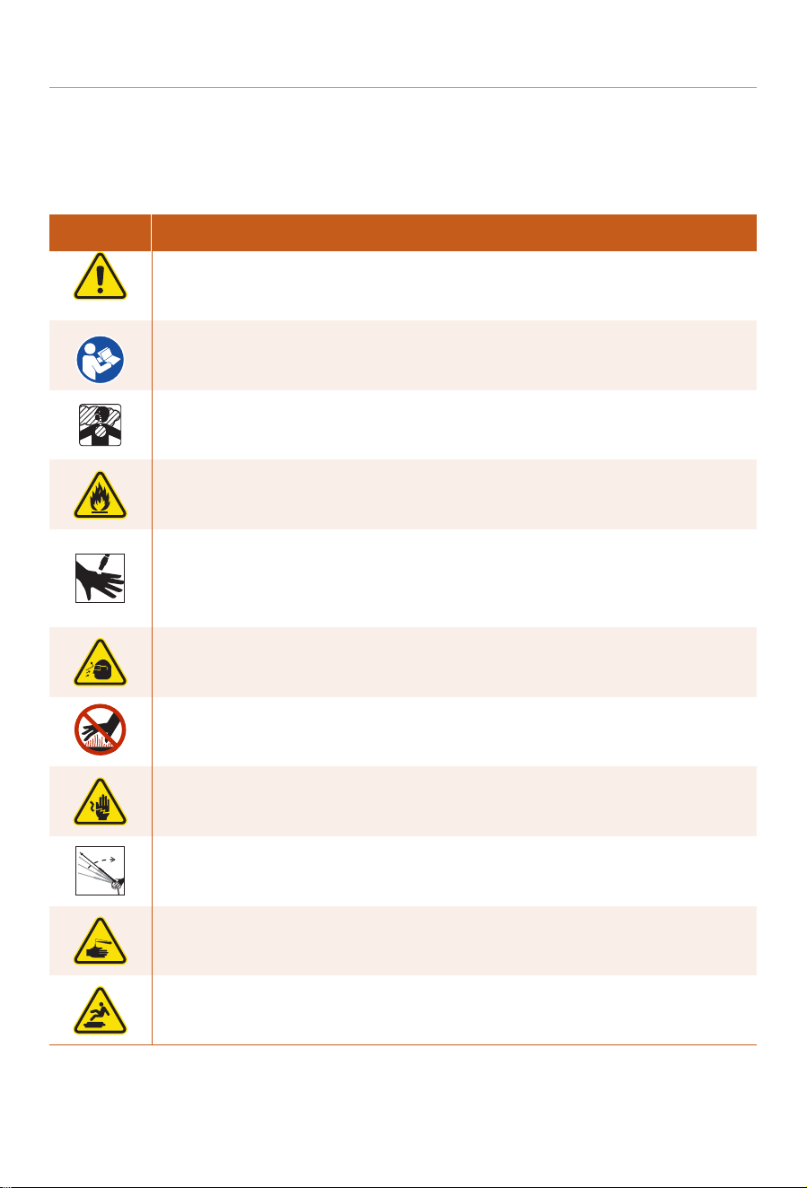
Safety Symbols
Some of the following symbols may be used on this product. Please study them and learn their meaning.
Proper interpretation of these symbols will allow you to safely operate the product.
SYMBOL
MEANING
-9-
Safety Alert Symbol. Indicates a potential personal injury hazard.
IMPORTANT SAFETY INSTRUCTIONS
PRESSURE WASHER
Toxic Fumes. Engine exhaust contains carbon monoxide,a poisonous gas that could
kill you in minutes.You cannot smell it or see it.
Risk of lnjections. To reduce the risk of injection or injury, never direct a water stream
towards peopleor pets or place any body part in the stream. Leaking hoses and fittings
are also capable of causinginjection injury. Do not hold hoses or fittings.
Spray,Flying Objects.Risk of eye injury. Spray could splash back or propel objects
resulting in serious injury.
Electric Shock.Contact with power source could cause electrical shock resulting in
death or serious injury.
Kickback. To reduce the risk of injury from kickback, hold the trigger gun securely with
both handswhen the machine is on.
Chemical Burn.Chemicals could cause burns resulting in death or serious injury.
Slippery Surface/Fall.Slippery wet surfaces could cause you to fall resulting in death or
serious injury.
Read Operator’s Manual. To reduce the risk of injury, user must read and understand
operator’s manual before using this product.
Risk of Fire. Fuel and its vapors are extremely flammable and explosive. Fire can cause
severe burns or death. Do not add fuel while the product is operating or still hot.
Hot Surface. To reduce the risk of injury or damage, avoid contact with any hot surface.
-10-
KNOW YOUR PRODUCT
KNOW YOUR PRODUCT
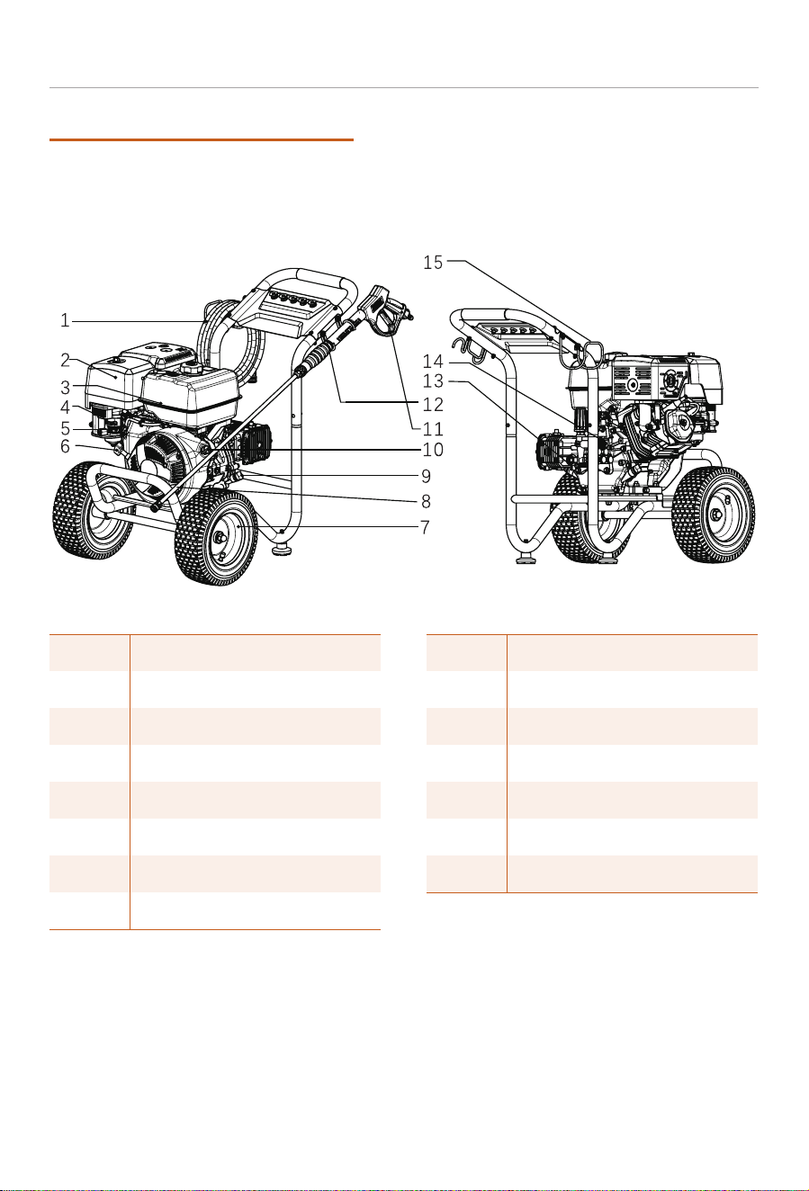
Please read this manual thoroughly before operating your product. Familiarize yourself with the location
and function of all controls and features. Failure to follow instructions could result in property damage,
serious injury or death. Save this manual for future reference.
High Pressure Hose
Air Filter
Fuel Tank
Choke Lever
Fuel Valve Lever
Recoil Start Handle
Wheel
Spray Wand
1
2
3
4
5
6
7
8
Oil Dipstick / Fill Cap
Ignition ON / OFF Switch
Spray Gun
Spray Gun Holder
Garden Hose Inlet
High Pressure Hose Outlet
High Pressure Hose Holder
9
10
11
12
13
14
15
PRESSURE WASHER
-11-
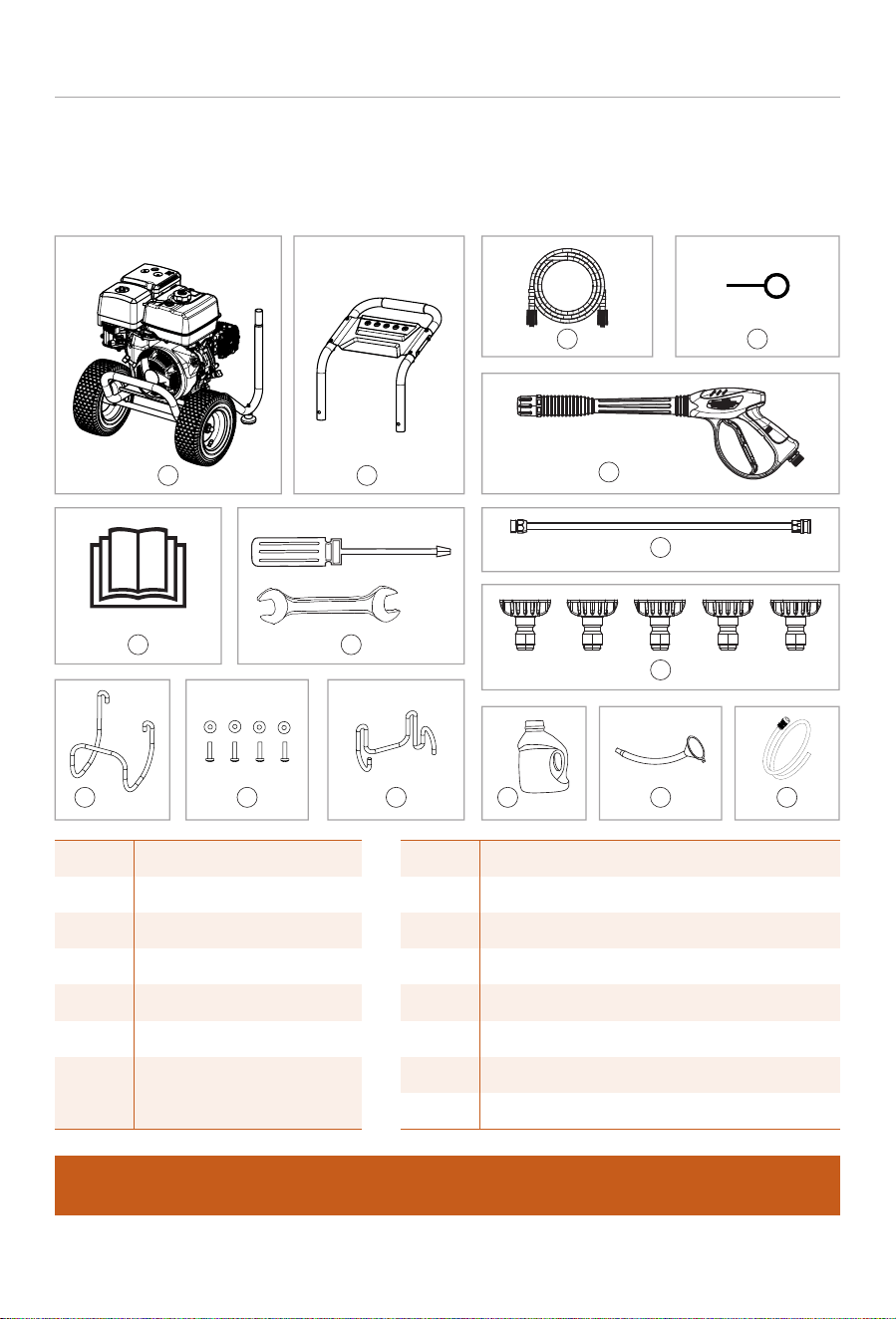
UNPACKING
Carefully remove the Pressure Washer out from the carton/box and place the unit on the ground or other
solid surface. Do not discard the packaging until you have confirmed the following items are present.
KNOW YOUR PRODUCT
PRESSURE WASHER
Main Unit
Upper Handle
High Pressure Hose
Nozzle Cleaning Tool
Spray Gun
Spray Wand
1
2
3
4
5
6
Operators Manual & Quick Start Guide
Tools – Wrench 10/8mm, Screwdriver
Wire Hanger – High Pressure Hose
4 x M6 Bolts, Washers
Holder – Spray Gun
Oil Bottle
Oil Funnel with tube
Chemical Injection Tube And Filter
8
9
10
11
12
13
14
15
Spray Nozzles (5 pcs)
0°, 15°, 25°, 40°, Soap
7
1
2
6
3
7
8 9
10 11 12 13 14
5
15
43
Please contact our customer support team at 1-888-676-7909 if any of the above loose parts are
missing from the carton.
-12-
ASSEMBLY
ASSEMBLY
PRESSURE WASHER
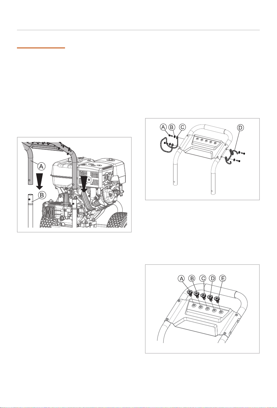
3. Spray Nozzles
Press the spray nozzles into their corresponding
color matched openings on the pressure washer’s
top panel.
(A) Red = 0°, (B) Orange = 15°, (C) Green = 25°, (D)
White = 40°, (E) Black = Soap
1. Install the Upper Handle
Align the two ends of the upper handle (A) with
the two upright tubes of the engine base (B), and
then press down firmly until positioning pins pop
into place on both sides.
2. Install the high-pressure hose
hook and spray gun hook
a. As shown in figure, install the high-pressure
pipe hook (C) on the left side of the upper
handle frame with 2 M6×25 bolts (A) 2 washers
6 (B).
b. As shown in figure, install the spray gun hook
(D) on the right side of the upper handle frame
with 2 M6×25 bolts (A) 2 washers 6 (B).
Your Pressure Washer requires limited assembly prior to use. If you have any questions regarding the
assembly of this product, call our Technical Support Team at 1-888-676-7909 M-F 8an-4pm CST or by
email at support@poulanpro-power.us Please have your model and serial number available at the time of
the call.
-13-
ASSEMBLY
PRESSURE WASHER
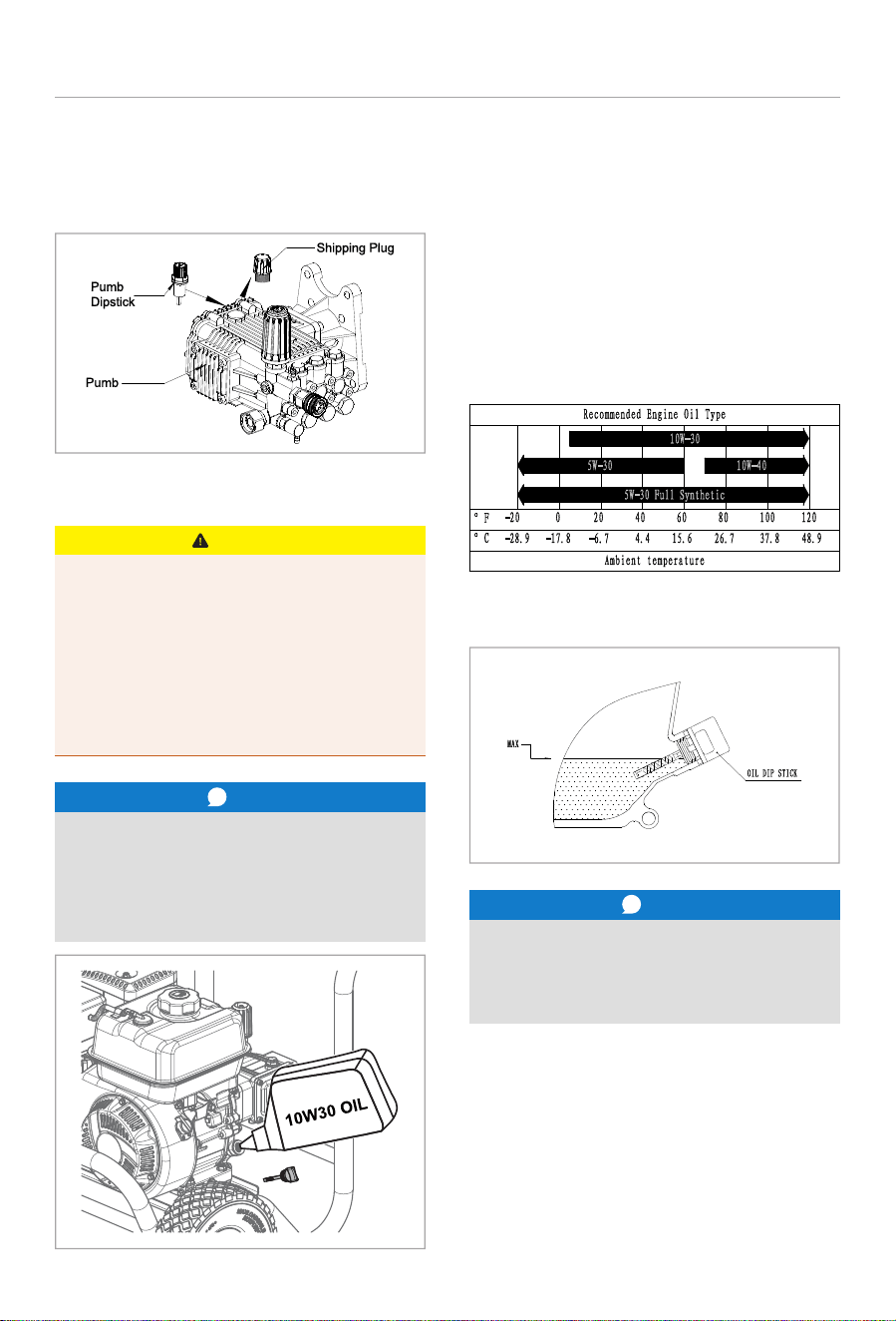
4. Pump Assembly
a. Remove the red shipping plug from the Pump
and replace with the included Pump Oil
Dipstick.
5.Add Engine Oil
This unit ships from our factory without oil.
DO NOT attempt to crank or start the engine
before it has been properly filled with the
recommended type and amount of oil.
Running an engine with a low oil level can
quickly cause engine damage. Damage to
the engine resulting from failing to follow
these instructions will void your warranty.
CAUTION
Recommended Engine Oil Type
Engine / Dipstick Oil Level
NOTE
...
Synthetic Oil may be used after the initial
20hr oil change. The use of synthetic oil does
not change the recommended oil change
intervals.
NOTE
...
SAE 10W-30 with a API service category of SJ
or higher is recommended for general use.
Other viscosities may be used when the
average temperature is within the
recommended range.
1. Place the unit on a flat, level surface.
2. Remove the oil dipstick by turning
counterclockwise.
3. Using a funnel, add up to 37oz.(1.1L) of oil to
the engine. The oil should be near the top
thread of the filler neck.
4. Check the oil level using the dipstick. DO NOT
screw in when checking.
5. When finished screw in the dipstick securely
and replace the oil / dipstick access cover.
ASSEMBLY
PRESSURE WASHER
-14-
6.Add Fuel
The engine was designed to operate on unleaded
gasoline with a octane rating of 87 or higher and
a maximum ethanol content of 10% by volume.
The use of fuels with a content of ethanol greater
than 10% can cause starting and/or performance
problems, damage to metal, rubber and plastic
parts of the fuel system. Engine performance
problems or damage caused by using fuel with a
higher ethanol content will not be considered for
warranty.
DANGER
Gasoline and gasoline vapors are highly
flammable and extremely explosive.
Always keep fueal away from sparks, open
flames, pilot lights, heat and other sources of
ignition.
Always Stop the engine and allow it to cool
before refueling.
Only fill or drain fuel outdoors in a well-
ventilated area.
DO NOT pump gasoline directly into the
engine. Use an approved container to transfer
the fuel to the engine.
Never use a gasoline container, gasoline tank,
or any other fuel item that is broken, cut, torn
or damaged.
DO NOT overfill the gasoline tank Wipe up
spills immediately.
IMPORTANT
Use fresh, clean unleaded fuel with a
minimum octane rating of 87 and a ethanol
content of 10% or less by volume.
Pouring gasoline too fast through the fuel
screen may result in blow back of gasoline at
the operator while filling.
WARNING
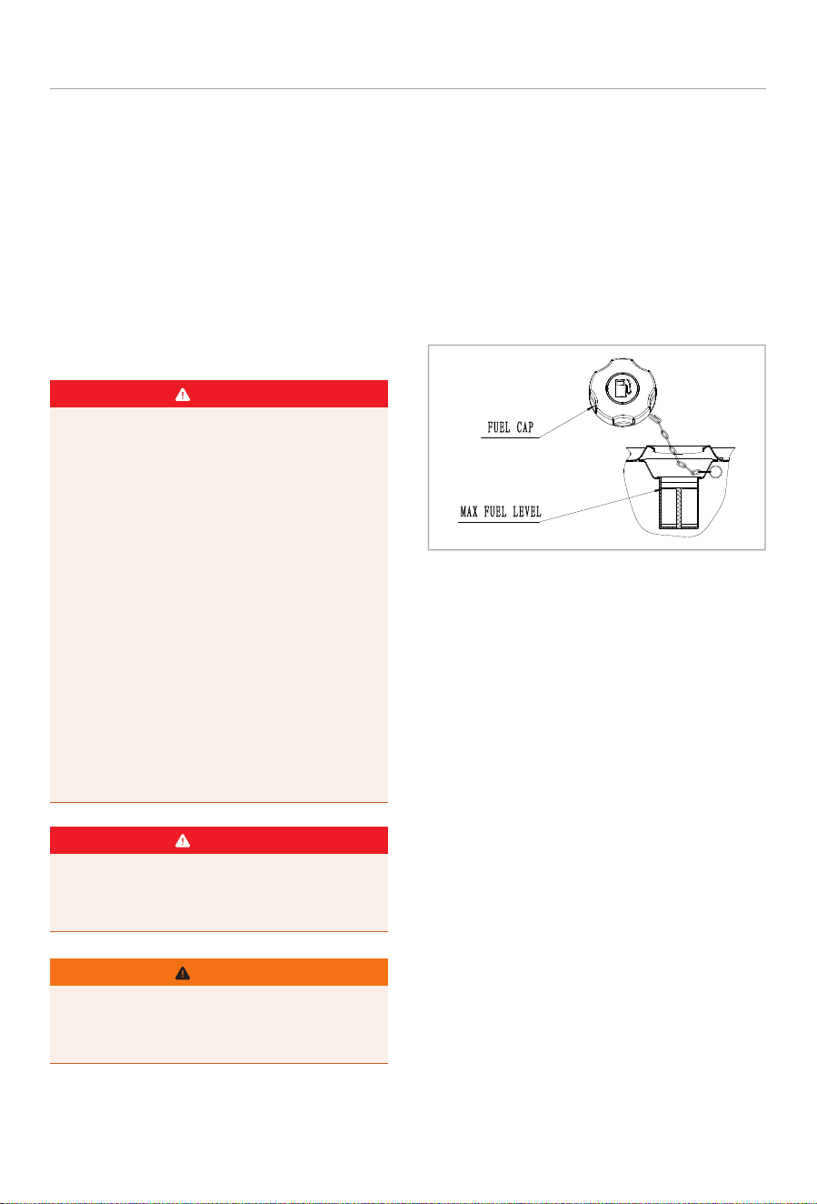
Filling the Fuel Tank
1. Remove the fuel tank cap.
2. Slowly add gasoline to the tank until it reaches
the Red fuel level indicator of the fuel screen.
DO NOT overfill. A minimum of ¼ in. (6.4 mm)
of space left in the tank is required for gasoline
expansion.
3. Replace and tighten the fuel tank cap.
4. Immediately wipe up any spills.
Notice: The engine works well with 10% or less
ethanol blended gasoline. When using ethanol-
gasoline blends there are some issues worth
noting:
Ethanol-gasoline blends can absorb more water
than gasoline alone.
These ethanol blends can eventually separate,
leaving water or a watery goo in the tank, fuel
valve and carburetor. The compromised gasoline
can be drawn into the carburetor and cause a
hard / no-start condition as well as damage to
the carburetor and the entire fuel system.
Creating potential hazards.
If a fuel stabilizer is used, confirm that it is
formulated to work with ethanol-gasoline blends.
Any damages or hazards caused by using ethanol
blended gasoline higher than 10% by volume,
improperly stored gasoline, and/or improperly
formulated stabilizers, are not covered by
manufacturer’s warranty.
It is advisable to always shut off the gasoline
supply and run the engine to starvation after each
use. See Storage instructions for extended non-
use.
ASSEMBLY
PRESSURE WASHER
-15-
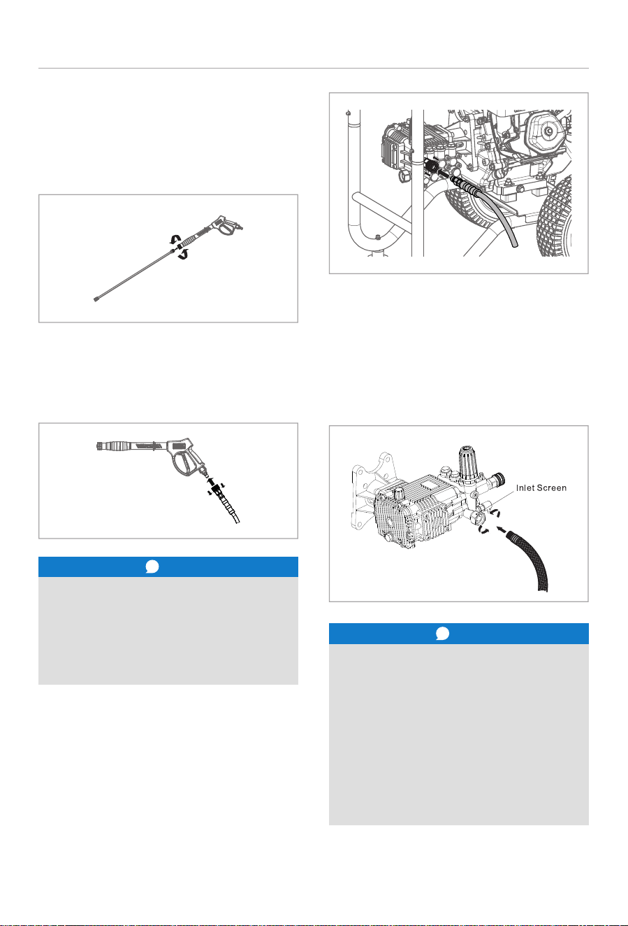
7. Assemble spray gun and
high-pressure hose
a. Attach the spray wand onto the gun by rotating
the coupler nut clockwise until hand tight. Do
not overtighten.
c. Uncoil and straighten the high-pressure hose to
prevent kinks.
d. Connect the open end of the high-pressure
hose to the high-pressure outlet by pulling the
quick connect collar back, inserting the high-
pressure hose and releasing the collar. Pull
firmly on the hose to ensure it is secure.
b. Attach the high-pressure hose to the spray gun
by pulling back on the quick connect collar of the
high-pressure hose, slide the fitting on the spray
gun into the quick connect and release the collar.
Pull firmly on the hose to ensure it is secure.
NOTICE
...
Never run the pressure washer without a
water supply connected to the pump and
turned on. Damage to the internal pump
components will result.
Internal pump damage from running a dry
pump is not covered under warranty.
8. Connect Water Supply - Garden Hose
e. Run water through the garden hose for a few
seconds to flush out debris from the hose.
f. Inspect the pump's inlet strainer and remove
any debris. Check for damage and if found
replace component.
g. With the water turned off, connect the garden
hose to the water inlet by turning the coupler
clockwise and tighten it by hand.
NOTICE
...
The water supply must come from a
pressurized water source. (Between 40-80
psi)
Do not use a gravity fed tank. Never use hot
water.
Garden hose is not to exceed 50ft.
There must be a minimum of 10 ft. (3 m) of
unrestricted hose between the pressure
washer and a pressurized source.
-16-
OPERATION
OPERATION
Before operating your machine, carefully read
and understand all safety, controls and
operating instructions in this Operator’s
Manual. Failure to follow these instructions
can result in serious personal injury. Take the
time to familiarize yourself with the controls
and operation of the entire unit before use.
WARNING
1. Engage the trigger safety lock on the spray gun.
2. Select a spray nozzle according to your
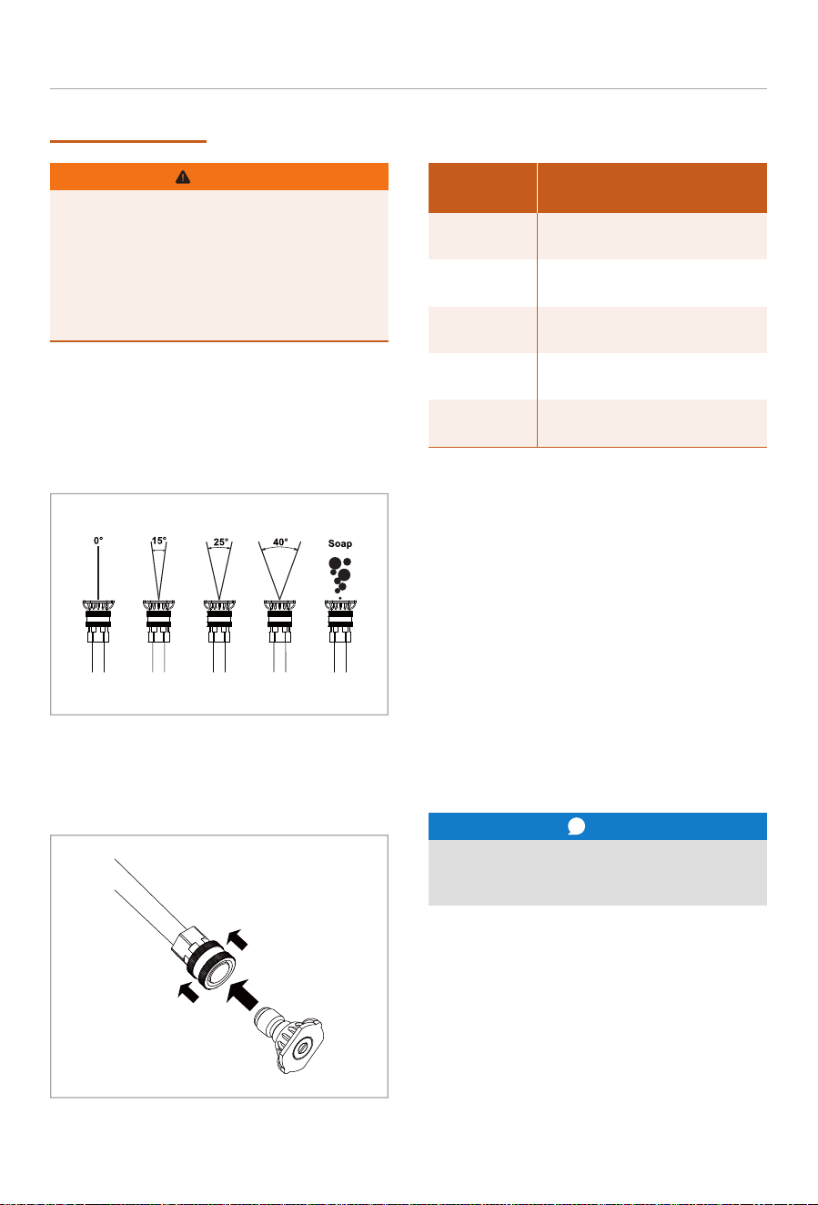
cleaning needs.
Connect Spray Nozzle
PRESSURE WASHER
3. Pull back on the spray wand quick connect
collar and insert the desired spray tip and
release the collar. Tug on the spray tip to ensure
it is firmly secure.
Choosing a location is critical to your AND others’
safety. Please read, understand and consider all
warnings when choosing the location.
A pressure washer must have at least 5 ft. (1.5 m)
of clearance from combustible material and allow
for adequate cooling,
Place the pressure washer on a flat level surface
in a well-ventilated area.
DO NOT place the pressure washer near vents or
intakes where exhaust fumes could be drawn into
occupied or confined spaces.
Carefully consider wind and air currents when
positioning pressure washer.
Pressure Washer Location
Nozzle
Tip Color
Black
White 40°
Green 25°
Orange 15°
Red 0°
Usage
Low Pressure Use to apply
Detergent
General Cleaning – Deck, Patio,
Fencing, Outdoor Equipment
Deep Cleaning - Siding, Gutters,
Deck, Patio, Outdoor Furniture
Concrete, Brick, Masonry,
Blacktop, Paint & Rust Removal
Use with extreme Caution. Paint
& Rust Removal, Concrete, Brick
NOTE
...
Do Not start the engine without a water
supply connected and turned on.
1. Uncoil and straighten out both the High-Pressure
Hose and Water line.
2. Turn on the water supply to the pressure wa sher.
3. Squeeze and hold the trigger on the spray gun
until a steady stream of water is flowing from the
spray nozzle tip. (10 – 15 seconds)
Important: Before Starting the Engine.
-17-
OPERATION
PRESSURE WASHER
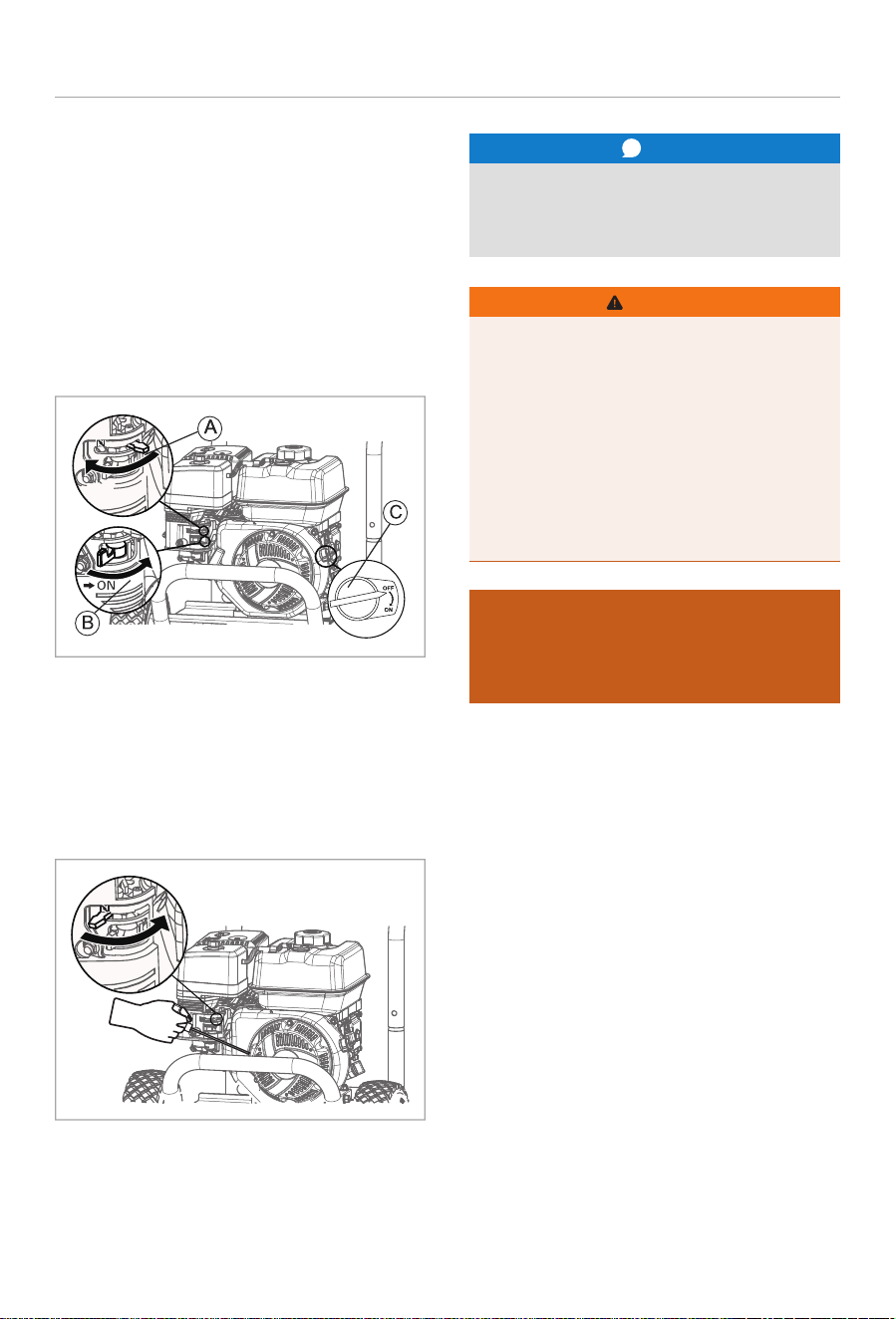
Starting the Engine
1. Check oil level and add oil if necessary.
2. Make certain the unit is on a flat, level surface.
3. Slide the Choke Lever (A) to the full CHOKE
position (Fully Left).
4. Move the Fuel Valve lever (B) to the ON position
(Fully Right).
5. Turn the Engine ignition switch (C) to the ON
position.
NOTE
...
If the engine does not start after 2 pulls,
relieve the pump pressure by pulling he
trigger on the spray gun.
Rapid retraction of the recoil cord will pull
hand and arm towards the engine faster than
you can let go. Broken bones, fractures,
bruises or sprains could result. Unintentional
startups can result in entanglement, traumatic
amputation or laceration.
When starting the engine, pull the recoil cord
slowly until resistance is felt and then pull
rapidly to avoid kickback.
WARNING
6. Pull the starter handle slowly until resistance is
felt, then pull rapidly. Note: Return the starter
handle slowly back to the engine to prevent
damage to the starter.
7. Once the engine starts, slowly slide the CHOKE
lever to the OFF position. (Fully Right).
If after several attempts the engine still does
not start, contact our Technical Support Team
at 1-888-676-7909 Mon-Fri 8-4 CST or Email:
support@poulanpro-power.us
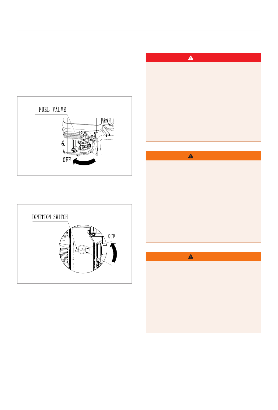
1. Move the Fuel Valve Lever fully to the left. (OFF
position).
Stopping the Engine
-18-
OPERATION
PRESSURE WASHER
In an Emergency:
Turn the engine switch to the “OFF” position.
2. Turn the engine ignition switch to the OFF
position.
Pressure Washer Operation
DANGER
Risk of injection or injury. High pressure jets
can be dangerous if subject to misuse.
DO NOT direct discharge stream at persons,
animals, electrical devices, or the machine
itself.
ALWAYS point spray gun in safe direction.
Every time you stop the engine, squeeze
trigger of spray gun to relieve any trapped
pressure.
Use of a pressure washer can create wet
slippery surfaces causing loose footing and
falls.
Operate the pressure washer on a level
surface.
Always grasp the spray gun with two hands to
reduce kickback and potential loss of footing.
Ensure there is proper drainage to disperse
the water.
WARNING
Risk of eye injury. Spray could splash back or
propel objects, resulting in serious injury.
Always wear vented safety goggles when
using or near this product. Safety glasses do
not provide full protection.
Always wear protective clothing sus as long-
sleeved shirts, long pants and closed toe
shoes when operating the pressure washer.
WARNING
Under Normal Operation:
-19-
OPERATION
PRESSURE WASHER
Pressure Washing
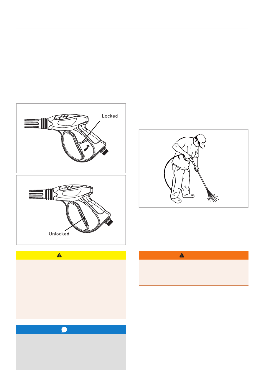
Once the engine is started firmly grasp the spray
gun with both hands. Point the spray gun in a safe
direction, disengage the spray gun trigger lock by
pressing down until it clicks into the back of the
trigger.
a. Depress the spray gun trigger to begin
spraying.
b. Release the trigger to stop spraying.
In the event the pump gets too hot a thermal
relief valve on the pump will open and
release hot water.
Running the unit for more than 1 minute
without spraying water will cause heat to
build up in the pump and cause damage to
the pump’s internal components which is not
covered under warranty.
CAUTION
NOTE
...
Never operate your pressure washer without
water.
Never connect your pressure washer to a hot
water source.
Spraying Tips
For most cleaning, keep nozzle 8 - 24 in. (20 - 61
cm) away from cleaning surface.
1. Test a small area first to understand if damage
may occur.
2. Continuously move the spray to evenly rinse the
surface to be cleaned.
3. When beginning to spray, start farther away
and move closer to avoid damage to the
surface.
4. Damage may occur to the cleaning surface if
you spray too close, especially with high-
pressure nozzles.
Shut Down
To reduce the risk of bodily injury or property
damage, Always follow the procedure below
once work is completed.
NEVER disconnect the high-pressure hose
from the machine while the system is
pressurized.
WARNING
1. Engage the spray gun safety lock.
2. Shut down the engine as per the recommended
procedure.
3. Turn off the water supply to the pressure
washer.
4. Disengage the spray gun safety lock and
squeeze the trigger for at least 15 seconds to
depressurize the system.
5. Re-engage the trigger lock on the spray gun.
OPERATION
PRESSURE WASHER
Use of Detergents
Use only detergents designed for pressure
washers.
Do not use household detergents, acids,
alkaline, bleaches, solvents, flammable
material, or industrial grade solutions, which
can damage the pump or cause property
damage. Many detergents may require
mixing prior to use. Prepare cleaning
solution as instructed on the solution bottle.
Always test in an inconspicuous area first.
NOTICE
...
-20-
1. Prepare the detergent solution as per the
detergents manufacturer’s instructions.
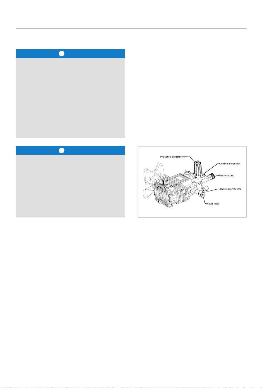
2. With the pressure washer shut off, connect the
chemical injection hose onto the barbed fitting
on the pump outlet.
3. Insert the filter screen end of the detergent
suction hose into the detergent bottle or
container.
4. With the trigger safety lock on the spray gun in
the locked position, install the quick connect
(Black) soap nozzle into the spray wand.
5. Turn on the water supply to the pressure
washer.
6. Start the engine and pull the trigger on the
spray gun to begin spraying the detergent.
a. For best results spray the surface evenly with
overlaps.
7. Once the detergent is fully applied to the
surface being cleaned, remove the detergent
suction hose and filter screen from the
detergent container and begin rinsing.
Detergent Dilution Ratio
Follow the pressure washer detergent
manufactures instructions for proper mix
ratios.
Detergent will only be drawn through the
spray gun with the black soap nozzle
attached to the end of the spray wand.
Flushing the system
To prevent leftover detergent from clogging or
gumming up the injection system it is important to
flush it with clear water after use.
1. If necessary, re-install the soap nozzle (BLACK).
2. Submerge the filter screen end of the detergent
hose into a container of clear water.
3. Operate the pressure washer for 1 - 2 minutes.
4. Once clean, stop the engine.
5. Turn off water supply.
6. Point spray gun in a safe direction. Squeeze the
trigger to release pressure within the system.
NOTICE
...

-21-
MAINTENANCE
MAINTENANCE
Proper maintenance of your unit is important for
maximum performance and a long service life.
To help you properly care for your unit, the
following section includes a maintenance
schedule and simple maintenance procedures.
We suggest working with an Authorized Dealer,
professional or qualified mechanic for any service
which you are unfamiliar with, not mechanically
proficient with or possessing the proper tools.
The maintenance schedule provided applies to
normal operating conditions. If your unit is
operated under more severe conditions such as
high-temperatures, sustained high-load or
operation in dusty or unusually wet conditions,
please inspect and service your unit more
frequently.
DANGER
DO NOT use gasoline or low flash point
solvents to clean the engine or any of its
components. The possibility exists of fire or
explosion which can damage the equipment
and cause severe bodily harm or even DEATH.
Some maintenance operations may require a
running engine. ALWAYS make sure the
maintenance area is well ventilated. Gasoline
engine exhaust contains poisonous carbon
monoxide gas that can result in
unconsciousness and/or DEATH when
inhaled.
WARNING
ALWAYS allow the engine to cool before
servicing. NEVER attempt to service a hot
engine.
CAUTION
ALWAYS disconnect the spark plug wire from
the spark plug and secure it away from the
engine before performing maintenance or
adjustments.
Failure to follow these instructions can result
in serious personal injury or property
damage.
CAUTION
NOTICE
...
Maintenance, replacement, or repair of
emission control devices and systems may be
performed by any non-road engine repair
establishment or individual.
PRESSURE WASHER
-22-
MAINTENANCE
Maintenance Schedule
Recommended
Maintenance Schedule
Engine Oil
Air Filter
Spark Plug
Fuel
Fuel Lines
Hardware-Bolts/Nuts
Carburetor
Air Cooling System
Valve Clearance
Pump - Damage / Leaks
Spray Gun
High Pressure Hose
Spray Gun O-rings
Water Inlet Screen
Each
Use
First 20
Hours or
1 Month
Every 50
Hours or
3 Months
Every 100
Hours or
Every Season
Every
300
Hours
Before
Storage
Check
Replace
Check
Clean
Check
Replace
Check Level
Drain
Check
Replace
Check
Drain
Clean
Check-Adjust
Check
Check
Change
Check
Check
Drain
Check / Lube
Check / Clean
X
X
X
X
X
X
X
X
X
X
X
X
X
X
X(1)
X (3)
X
X (1)
X
X (1)
X
X
X
X
X
X
X
X (2)
X (3)
X
X
X
X
X
1. Service more frequently when used in dusty conditions - Replace if worn or damaged.
2. These items should be maintained and repaired by an authorized dealer, unless the owner has
appropriate tools and is proficient with mechanical maintenance.
3. Pump Oil change – After first 50 hours of use. Then every 500 hours thereafter.
PRESSURE WASHER
Pump Oil
-23-
MAINTENANCE
Oil Change
NOTICE
...
Used oil is a hazardous waste product and
must be disposed of properly. Check your local
regulations for proper disposal/recycling
facilities.
Change the engine oil after the first 20 hours of
use. Thereafter, change the oil every 100 hours of
use or every season. Change the oil more often if
used in dusty conditions.
If possible, drain the oil while the engine is warm.
Warm oil drains more quickly and completely.
Refer to the adding engine oil section for the
recommended oil for your operating environment.
1. Place the pressure washer on a flat level
surface.
2. Place a suitable container below the oil drain
plug to catch the used oil.
3. Remove the oil filler cap/dipstick and the drain
plug bolt and sealing washer from the engine.
4. Allow the oil to drain completely from the
engine.
5. Reinstall and tighten the drain plug bolt with
sealing washer.
6. Using a funnel, add up to 20.3 fl. oz. (0.6 L) of
oil to the engine.
7. Check the oil level using the dipstick. DO NOT
screw in when checking.
8. When finished screw in the dipstick / oil fill cap
securely.
Air Filter
Check the air filter after the first 20 hours of use
and clean the filter every 50 hours of use. Clean
the filter more often when operating in a dusty
environment. Replacement of the air filter is
highly recommended at the first sign of excessive
dirt build-up, element breakdown, wear or
damage.
Inspection & Cleaning
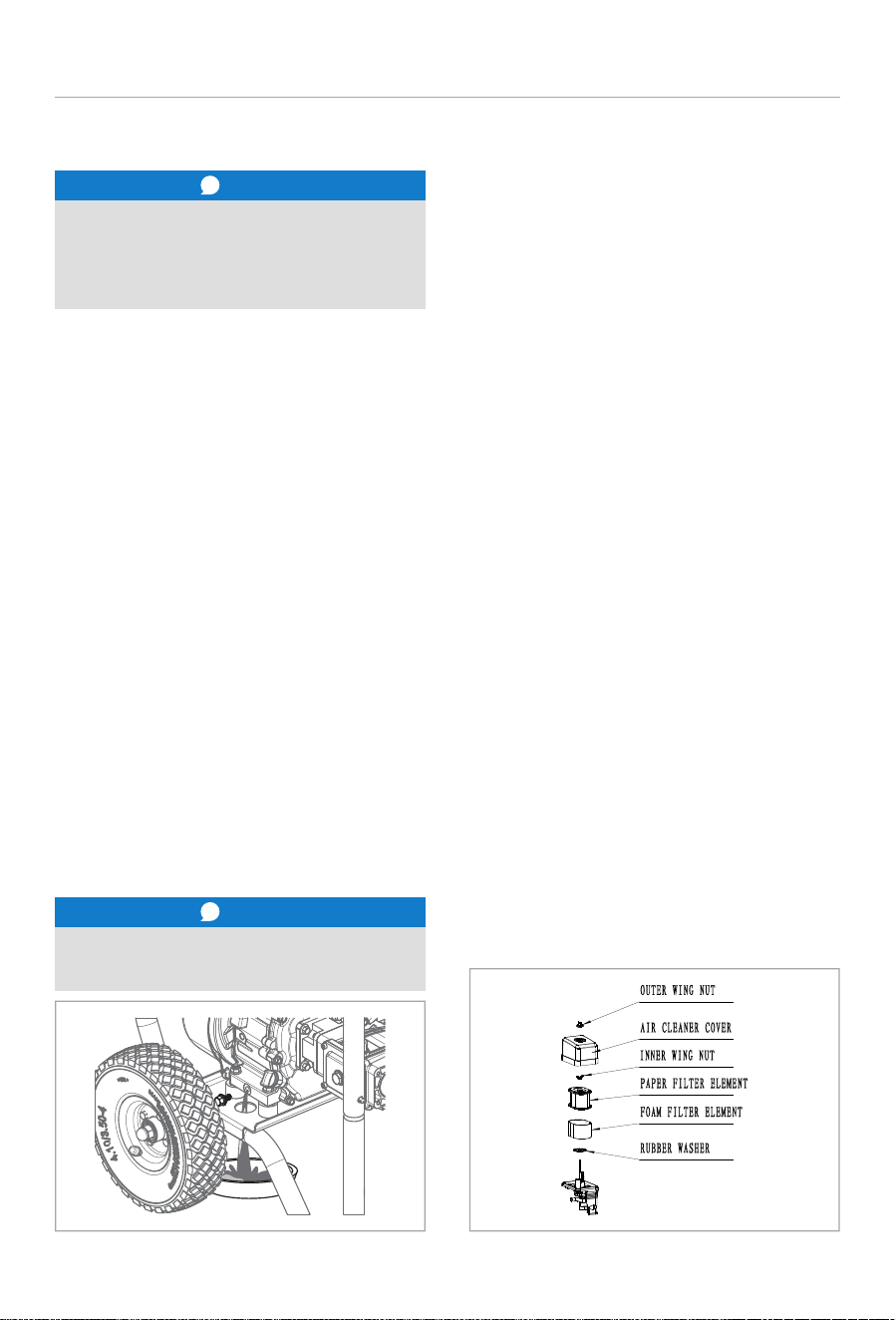
1. Remove the outer wing nut and air filter cover.
2. Unscrew the inner wing nut and remove the air
filter element.
3. Remove the outer foam pre-filter from the
paper filter. Check both elements for tears or
holes. Replace the filter if damaged.
4. Paper Element - To remove the dirt, tap it
several times on a hard surface. Replace the
element if excessively dirty. Do Not use
pressurized air or solvents to clean the air filter
as damage can occur.
5. Foam Pre-Cleaner – Clean the pre-cleaner in
warm soapy water and rinse. Squeeze out
excess water from the filter and allow to dry
completely before installation.
6. Being careful to prevent dirt from entering the
air duct leading to the carburetor, wipe any dirt
from the air filter housing and cover.
7. Install the foam pre-filter over the air filter
element, install onto the housing. Secure the air
filter with the inner wing nut making sure it is
sitting flat and sealing on the housing base.
Install the air cleaner cover and tighten the
outer wing nut.
PRESSURE WASHER
NOTICE
...
Dispose of the used oil in accordance with
local laws and regulations.
-24-
MAINTENANCE
Spark Plug
The spark plug is an important part of the engine
and its operation and should be checked
regularly.
Check the spark plug after the first 20 hours and
every 100 hours of operation thereafter. Replace
the spark plug after 300 hours of operation.
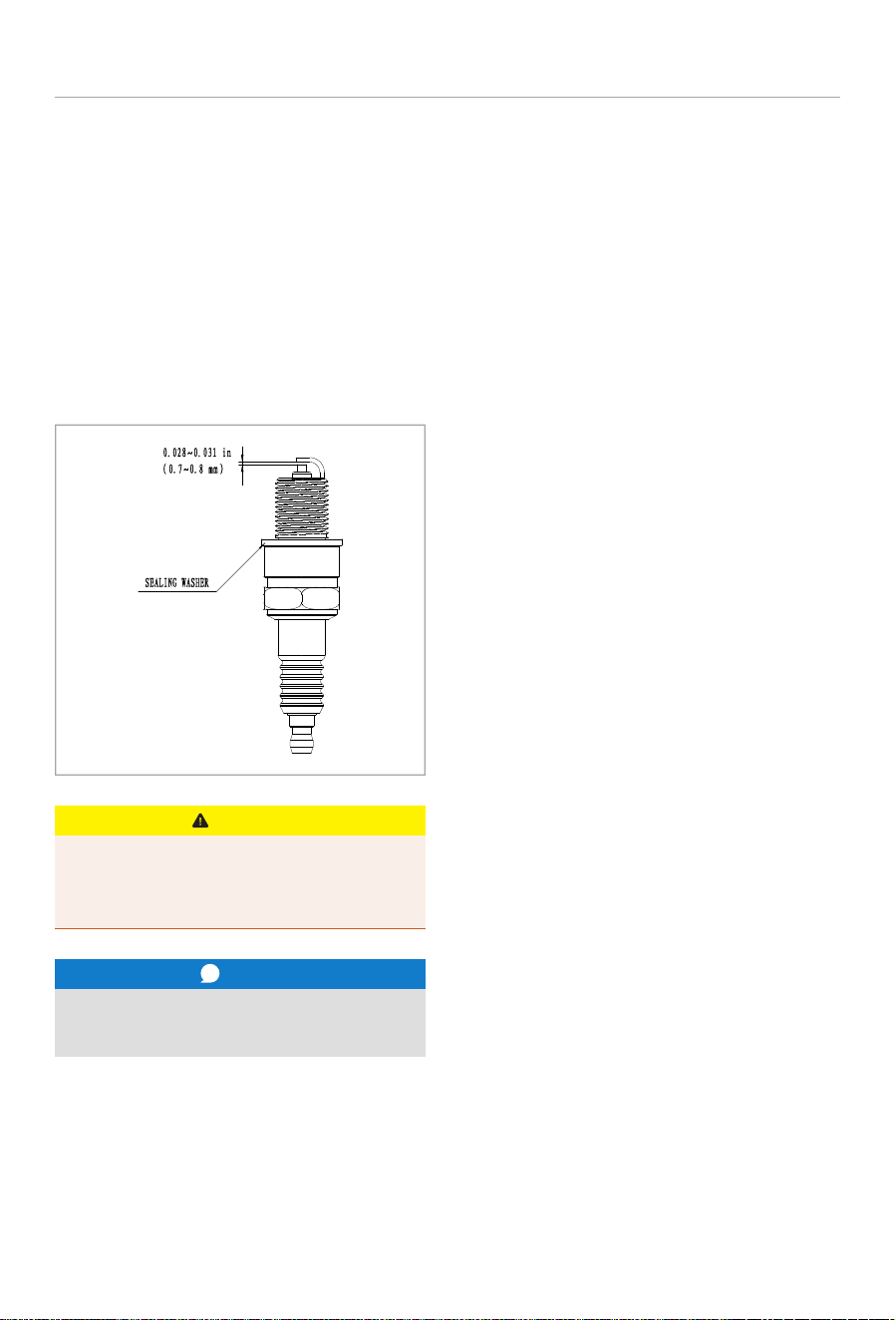
Recommended Spark Plug: Torch F7RTC or
Equivalent
Spark Plug Gap: .028 - .031 in. (0.7-0.8mm)
Always allow the engine to cool before
performing maintenance, adjustments or
service.
CAUTION
A loose spark plug can overheat and damage
the engine
NOTICE
...
1. Remove the spark plug cap and clear away any
dirt around the spark plug base.
2. Using a spark plug wrench, remove the spark
plug.
3. Visually check the spark plug. Clean with a steel
brush. If the insulator is damaged, replace the
spark plug.
4. Measure the spark plug gap with a suitable
gauge. Adjust the spark plug gap as necessary
by carefully bending the ground electrode.
5. To prevent cross threading, thread the spark
plug in by hand until it seats, then tighten with
a spark plug wrench as follows.
New Spark Plug – Tighten ½ turn after the plug
seats to the cylinder head.
Used Spark Plug – Tighten ½ to ¼ turn after the
plug seats to the cylinder head.
6. Reconnect the spark plug cap.
PRESSURE WASHER
Spark Plug Cleaning / Adjusting
/ Replacement
Pressure Washer
MAINTENANCE
PRESSURE WASHER
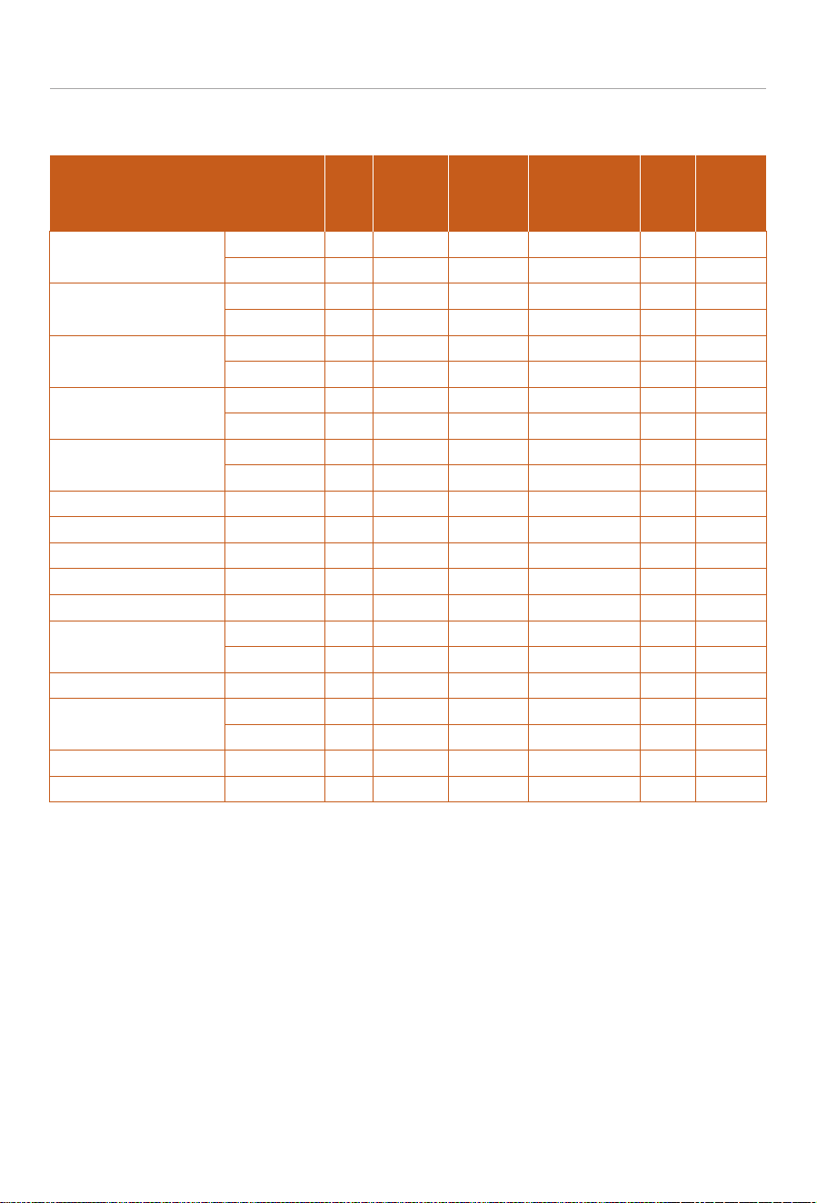
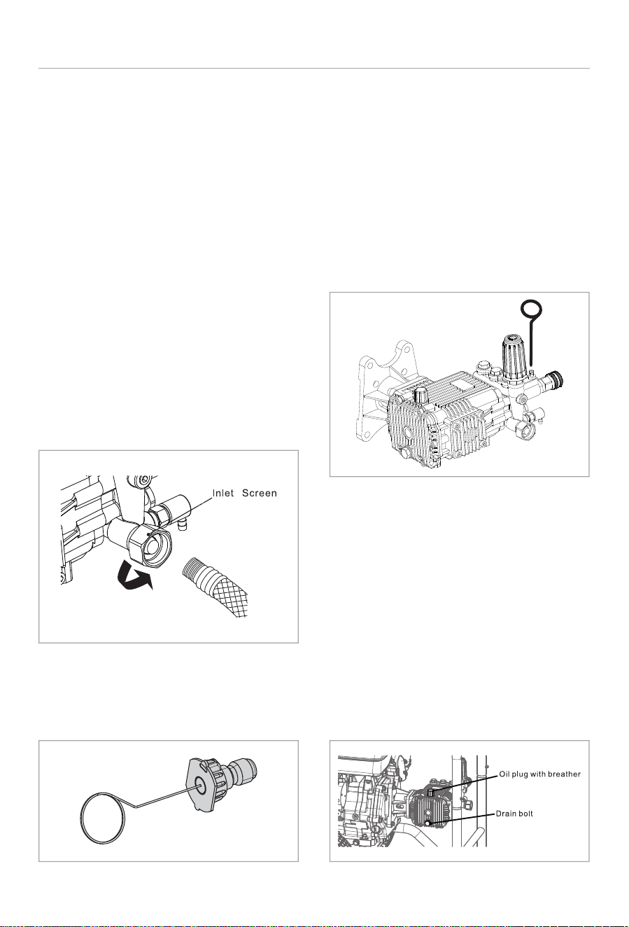
1.High Pressure Hose
a. Lubricate the o-ring at the wand / gun unio.
Inspect for cracks or damage. Replace if
needed.
b. Check the operation of the spray gun trigger to
ensure it springs back when released. Inspect
the trigger lock for proper function.
2. Spray Gun
Check & clean the water inlet screen (water supply
line side). If screen or gasket are damaged
replace.
3. Water Inlet
Using a nozzle cleaning tool or small wire to
loosen up any particles or debris in the nozzle
and flush with water.
4. Spray Nozzles
-25-
The check ball in the detergent siphoning system
can become stuck from mineral deposits or dried
detergent. To free up the check ball perform the
following.
a. Remove the detergent hose from the barbed
fitting of the check valve. (located on pump).
b. Insert the nozzle cleaning tool or small wire
into the barbed fitting and push down until the
check ball moves.
c. Reinstall the detergent hose onto the check
valve fitting.
5. Detergent Siphoning Check Ball
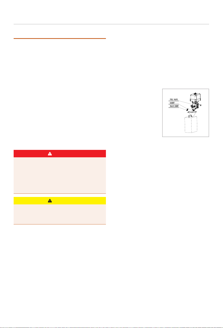
6. Change Pump Oil
a. Inspect high-pressure hose for cuts, bulges, or
leaks due to kinks or abrasion. If damage is
found, replaced immediately.
b. Inspect the connection fittings for dents, cracks,
abrasions or other damage. Replace if found.
The recommended oil change is after the first 50
hours of use. Then every 500 hours.
a. Turn off engine.
b. Cean the area around the oil pump dipstick and
drain bolt.
c. Place a pan under the drain bolt to collect the
oil.
d. Remove the oil drain bolt and dipstick from the
pump and allow to drain.
Once drained completely, reinstall the oil drain plug
and refill the pump. SAE 15W-40 12 oz. (0.35mL)
-26-
TRANSPORTATION AND STORAGE
TRANSPORTATION AND STORAGE
Transporting
If the unit has been running, allow it to cool
before transporting. A hot muffler can cause
burns and/or ignite nearby materials. To prevent
fuel spills, always transport the pump in an
upright position.
1. Turn the Engine switch to the OFF position.
2. Move the Fuel Valve Lever to the OFF position.
3. Strap or tie the unit down to prevent any sliding
or tipping
Off-Season Storage
Storage preparation is important for keeping your
unit running trouble free, easier to start after
storage and the overall service life of your unit.
When the unit will not be used for more than 30
days, prepare it for storage as follows:
DANGER
GASOLINE AND GASOLINE VAPORS ARE HIGHLY
FLAMMABLE AND EXPLOSIVE.
Fire or explosion can cause property damage,
severe burns or death.
Only fill or drain fuel outdoors in a well-
ventilated area.
Always allow the engine to cool before
performing maintenance, adjustments or
service.
CAUTION
Engine
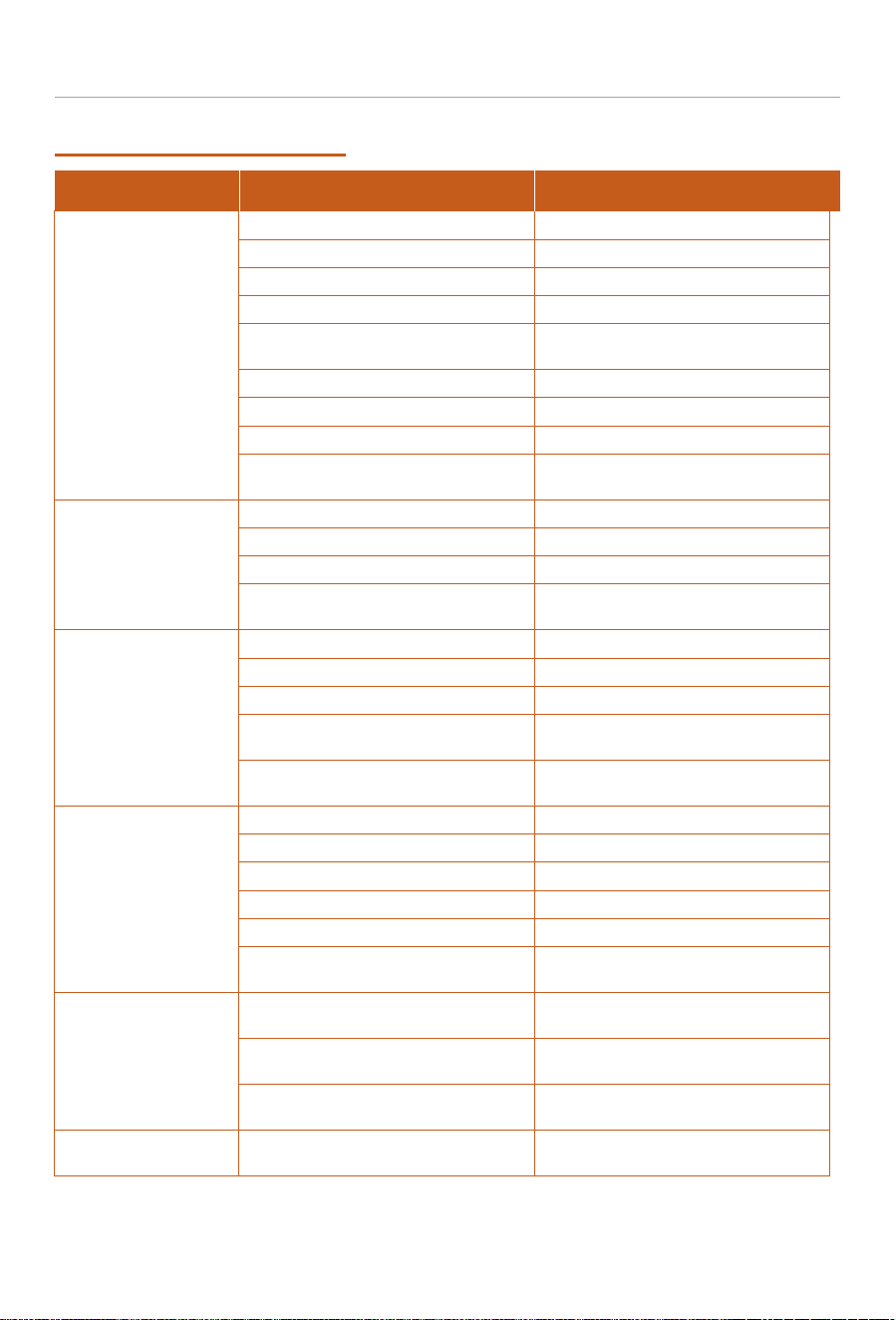
Drain the fuel tank and carburetor
1. Move the fuel valve lever to the OFF position.
2. Remove the carburetor drain screw and drain
fuel into an approved gasoline container.
3. Slide the fuel valve lever to the ON position,
allowing the fuel from the fuel tank to
completely drain through the carburetor bowl.
4. Once draining is
complete, reinstall
the carburetor drain
screw.
5. Move the Fuel valve
lever to the OFF
position.
6. Properly handle and
dispose of drained
fuel.
Oil
1. Change the engine oil. (See “Oil Change” in
the Maintenance section)
2. Remove the Spark Plug.
3. Pour approximately one teaspoon of clean
engine oil (5 cc) into the spark plug hole.
4. Slowly pull the starter rope several times to
lubricate the cylinder walls of the engine.
5. Replace the spark plug and tighten 1/8 to ¼
turn after the spark plug seats to the cylinder
head.
Pump
1. Disconnect and drain all hoses, spray gun and
spray wand.
2. Remove all liquids from the pump by slowly
pulling the recoil handle 6-8 times.
3. The use of a pump protector product is
recommended. If not available, connect a 3 ft.
(1 m) of garden hose to the water inlet. Pour
approx.. 6 oz (177.4 mL) of RV-antifreeze into
the hose, then pull the recoil handle several
times until the antifreeze exits the pump high
pressure outlet.
Storage Location
Store your unit in a dry, well-ventilated place out
of direct sunlight. Place a fabric cover over the
unit. Do not use a plastic or vinyl cover as
condensation could be trapped underneath which
could increase the chances of rusting.
PRESSURE WASHER
It is important to prevent gum deposits from
forming in essential fuel system parts such as
carburetor, fuel hose, or tank during storage.
Fuel Stabilizer
Fuel stabilizers are an acceptable alternative in
minimizing the formation of fuel gum deposits
during storage. Add stabilizer to gasoline in fuel
tank or storage container. Always follow the mix
ratio found on stabilizer container. Run the engine
at least 10 minutes after adding stabilizer to allow
the stabilizer to reach the carburetor. Do not
empty the gas tank and carburetor if using fuel
stabilizer.
-27-
TROUBLESHOOTING
TROUBLESHOOTING
Problem
Engine does not start
Engine runs poorly
The engine starts,
then shuts down after
a short period
Cause Solution
Dirty or Faulty Spark Plug.
Spark plug wire loose.
Fuel tank is empty.
Choke control in incorrect position.
Old fuel or water in fuel.
Dirty air filter.
Switch is in "OFF" position.
Low Oil Level.
No spark.
Defective or incorrectly gapped spark plug.
Plugged spark arrestor screen.
Dirty air filter.
Stale gasoline.
Low fuel level.
Low oil level.
Float in carburetor is damaged or sticking.
Fuel is contaminated or deteriorated.
Carbon deposit and buildup on spark plug
electrode.
Water supply is restricted.
Garden hose is to small.
Inlet filter screen is clogged.
Low water pressure at inlet.
Spray tip is obstructed.
Connections, high pressure hose or spray
gun leak.
High pressure spray nozzle is installed.
Detergent siphoning hose is clogged,
cracked or not connected.
Check ball is stuck in detergent siphoning
system.
Pump has built up pressure from attempted
starts or failure to relieve pump pressure.
PRESSURE WASHER
The pump does not
produce pressure,
loss of pressure,
low water volume
Soap wash is not
functioning
Recoil start handle
won’t or is hard to pull
Clean and adjust or replace spark plug.
Reconnect wire.
Refuel.
Move switch to CHOKE position.
Drain the fuel tank and carburetor. Refuel
with fresh gasoline.
Clean or replace filter.
Turn switch to "ON" position.
Fill to proper level, place on flat, level surface.
Check engine switch is in ON position, Check
oil level, Check / replace spark plug.
Inspect spark plug gap or replace spark plug.
Clean spark arrestor.
Clean or replace the air filter.
Drain the fuel tank and carburetor.
Refuel with fresh gasoline.
Refuel.
Add engine oil.
Have the carburetor cleaned or rebuilt.
Drain & replace the fuel in the fuel tank and
carburetor bowl.
Clean and re-gap or replace spark plug.
Check hose for leaks, links, blockage.
Replace with min 5/8” hose.
Clean out and rinse filter screen.
Turn garden hose on to full force.
Clean spray tip.
Tighten connections, replace O-rings or
replace failed piece.
Replace with (Black) low pressure soap
nozzle.
Check siphoning hose connection, blockage
or cracks. Clean or replace as needed.
Free the check ball. See Maintenance.
Pull spray gun trigger before each starting
attempt and after 2 pulls of the recoil.
-28-
BASIC SERVICE PARTS LIST
BASIC SERVICE PARTS LIST
Basic Common Service Parts
Service Part
Part Number
2204700002-0001
1901100165-0001
1101500004-0001
1800900009-0001
360290006
3412100002-0001
2205000001-0001
2000100359-0001
3901100004-0001
3901000002-0001
3900900002-0001
3901200005-0001
3901200009-0001
3901200008-0001
3901200007-0001
3901200006-0001
Spark Plug – F7RTC
Air Filter Assy w/pre-cleaner
Dipstick Assy
Fuel Cap
Oil Drain Bolt
Sealing Washer - Oil Drain
Engine On / Off Switch
Recoil Starter Assy
High Pressure Hose
Spray Wand
Spray Gun
Spray Nozzle – Black Soap
Spray Nozzle – White 40°
Spray Nozzle – Green 25°
Spray Nozzle – Orange 15°
Spray Nozzle – Red 0°
PRESSURE WASHER
For additional service or parts assistance, Contact Us at 1-888-676-7909 or visit the support page of our
website at www.poulanpro.com.

-29-
WARRANTY STATEMENT
PRESSURE WASHER
WARRANTY STATEMENT
2-Year Limited Warranty
Terms and Conditions
PoulanPro® is a registered trademark of
Husqvarna AB and is used under license to Novus
Performance Products LLC. Novus products are
warranted for two (2) years against defects in
materials or workmanship when put to ordinary
and normal consumer use; ninety (90) days for
any other use.
For the purposes of all the above warranties,
“ordinary and normal consumer use” refers to
non-commercial residential use and does not
include misuse, accidents or damage due to
inadequate maintenance. Novus Performance
Products LLC certifies that Novus Products are fit
for ordinary purposes for which a product of this
type is used. Novus Performance Products LLC,
however, limits the implied warranties of
merchantability and fitness in duration to a period
of two (2) years in consumer use, ninety (90) days
for any other use.
The 2-Year Limited Warranty on Novus Products
starts on the purchase date. The 2-Year Limited
Warranty is applicable only to the original owner.
The warranty holder is responsible for the
performance of the required maintenance as
defined by the manufacturer's owner's manuals.
The warranty holder is responsible for
replacement of normally wearing parts such as
the Belt, Shear Pins, Spark Plug and Air Filter.
Accessories to the machine are not covered by
this warranty.
During the warranty period, the warranty holder is
responsible for the machine transportation
charges, if required.
During the warranty period, warranty parts will be
shipped by standard method at no charge to the
warranty holder. Expedited shipping of warranty
parts is the responsibility of the warranty holder.
SOME STATES DO NOT ALLOW LIMITATIONS ON THE
LENGTH OF IMPLIED WARRANTIES, SO THE ABOVE
LIMITATIONS MAY NOT APPLY TO YOU.
Novus Performance Products LLC shall not be
liable under any circumstances for any incidental
or consequential damages or expenses of any
kind, including, but not limited to, cost of
equipment rentals, loss of profit, or cost of hiring
services to perform tasks normally performed by
Novus Products.
SOME STATES DO NOT ALLOW THE EXCLUSION OR
LIMITATION OF INCIDENTAL OR CONSEQUENTIAL
DAMAGES, SO THE ABOVE LIMITATIONS MAY NOT
APPLY TO YOU.
THIS WARRANTY GIVES YOU SPECIFIC LEGAL
RIGHTS, AND YOU ALSO HAVE OTHER RIGHTS,
WHICH VARY FROM STATE TO STATE.
Technical Support:
Toll free: 1-888-676-7909 Mon-Fri 8-4 CST
Email: support@poulanpro-power.us

-30-
WARRANTY STATEMENT
U.S. FEDERAL EMISSION CONTROL WARRANTY STATEMENT
YOUR WARRANTY RIGHTS AND OBLIGATIONS
PRESSURE WASHER
The United States Environmental Protection Agency and Novus Performance Products LLC (Novus) are
pleased to explain the emissions control system warranty on your 2024-2025 small off-road
engine/equipment (SORE). In the United States, new equipment that use small off-road engines must be
designed, built, and equipped to meet the State's stringent anti-smog standards. Novus must warrant the
emissions control system on your small off-road engine/equipment for the periods of time listed below
there has been no abuse, neglect or improper maintenance of your small off-road engine or equipment
leading to the failure of the emissions control system.
Your emissions control system may include parts such as the carburetor or fuel-injection system, the
ignition system, catalytic converter, fuel tanks, fuel lines (for liquid fuel and fuel vapors), fuel caps, valves,
canisters, filters, clamps and other associated components. Also included may be hoses, belts,
connectors, and other emission-related assemblies.
Where a warrantable condition exists, Novus will repair your small off-road engine/equipment at no cost
to you including diagnosis, parts and labor.
This emissions control system on your small off-road engine/equipment is warranted for two years. If any
emission-related part on your small off-road engine/equipment is defective, the part will be repaired or
replaced by Novus.
As the small off-road engine/equipment owner, you are responsible for the performance of the required
maintenance listed in your owner's manual. Novus recommends that you retain all receipts covering
maintenance on your small off-road engine/equipment, but Novus cannot deny warranty coverage solely
for the lack of receipts or for your failure to ensure the performance of all scheduled maintenance.
As the small off-road engine/equipment owner, you should however be aware that Novus may deny you
warranty coverage if your small off-road engine/equipment or a part has failed due to abuse, neglect, or
improper maintenance or unapproved modifications.
You are responsible for presenting your small off-road engine/equipment to a Novus distribution center or
service center as soon as the problem exists. The warranty repairs shall be completed in a reasonable
amount of time, not to exceed 30 days. If you have any questions regarding your warranty rights and
responsibilities, you should contact:
Novus Performance Products LLC
customer service representative
1-800-409-7802
Email: Support@novuspowerequipment.com
MANUFACTURER'S WARRANTY COVERAGE:
OWNER'S WARRANTY RESPONSIBILITIES:

DEFECTS WARRANTY REQUIREMENTS
-31-
WARRANTY STATEMENT
(a) Applicability. This section applies to emissions
control systems on small off-road engines or
equipment that use small off- road engines subject to
the emission standards in this Article. The warranty
period begins on the date the engine or equipment is
delivered to an ultimate purchaser and extends for a
period of two years.
(b) General Emissions Warranty Coverage. The engine
or equipment must be warranted to the ultimate
purchaser and any subsequent owner that the
emissions control system when installed was:
(1) Designed, built, and equipped so as to conform
with all applicable regulations; and
(2) Free from defects in materials and workmanship
that causes the failure of a warranted part for a
period of two years.
(c) The warranty on emissions-related parts will be
interpreted as follows:
(1) Any warranted part that is not scheduled for
replacement as required maintenance in the written
instructions required by subsection (e) must be
warranted for the warranty period defined in
subsection (b)(2). If any such part fail during the
period of warranty coverage, it must be repaired or
replaced by Novus or it’s contracted warranty provider
according to subsection (4) below. Any such part
repaired or replaced under the warranty must be
warranted for a time not less than the remaining
warranty period.
(2) Any warranted part that is scheduled only for
regular inspection in the written instructions required
by subsection (e) must be warranted for the warranty
period defined in subsection (b)(2). A statement in
such written instructions to the effect of “repair or
replace as necessary” shall advise owners of the
warranty coverage for emissions related parts.
Replacement within the warranty period is covered by
the warranty and will not reduce the period of
warranty coverage. Any such part repaired or
replaced under warranty must be warranted for a
time not less than the remaining warranty period.
(3) Any warranted part that is scheduled for
replacement as required maintenance in the written
instructions required by subsection (e) must be
warranted for the period of time prior to the first
scheduled replacement point for that part. If the part
fails prior to the first scheduled replacement, the part
must be repaired or replaced by Novus according to
Subsection (4) below. Any such part repaired or
replaced under warranty must be warranted for a
time not less than the remainder of the period prior to
the first scheduled replacement point for the part.
(4) Repair or replacement of any warranted part
under the warranty provisions of this article must be
performed at no charge to the owner at a warranty
station.
(5) Notwithstanding the provisions of subsection (4)
above, warranty services or repairs must be provided
at distribution centers that are franchised to service
the subject small off-road engine/equipment.
(6) The small off-road engine/equipment owner must
not be charged for diagnostic labor that leads to the
determination that a warranted part is in fact
defective, provided that such diagnostic work is
performed at a warranty station.
(7) Throughout the emissions control system’s
warranty period set out in subsection (b)(2), Novus or
it’s contracted warranty provider must maintain a
supply of warranted parts sufficient to meet the
expected demand for such parts and must obtain
additional parts if that supply is exhausted.
(8) Manufacturer-approved replacement parts that do
not increase the exhaust or emissions of the engine or
emissions control system must be used in the
performance of any warranty maintenance or repairs
and must be provided without charge to the owner.
Such use will not reduce the warranty obligations of
Novus or it’s contracted warranty provider.
(9) The use of add-on or modified parts may be grounds
for disallowing a warranty claim made in accordance
with this Article. Novus or it’s contracted warranty
provider will not be liable under this Article to warrant
failures of warranted parts caused by the use of an add-
on or modified part.
(10) Novus shall provide any documents that describe
that it’s warranty procedures or policies within five
working days of request by the Executive Officer.
(d) A list of all emissions warranty parts must be
included with each new engine or equipment subject
to this Article. The emissions warranty parts list shall
include all parts whose failure would increase
exhaust and evaporative emissions, and contains the
following parts:
EMISSIONS PARTS LIST
Exhaust Emission
(1) Fuel Metering System
(A) Carburetor and internal parts (and/or pressure
regulator or fuel injection system).
PRESSURE WASHER

-32-
WARRANTY STATEMENT
(B) Air/fuel ratio feedback and control system.
(C) Cold start enrichment system.
(2) Air Induction System
(A) Controlled hot air intake system.
(B) Intake manifold.
(C) Air filter.
(3) Ignition System
(A) Spark Plugs.
(B) Magneto or electronic ignition system.
(C) Spark advance/retard system.
(4) Exhaust Gas Recirculation (EGR) System
(A) EGR valve body, and carburetor spacer if
applicable.
(B) EGR rate feedback and control system.
(5) Air injection System
(A) Air pump or pulse valve.
(B) Valves affecting distribution of flow.
(C) Distribution manifold.
(6) Catalyst or Thermal Reactor System
(A) Catalytic converter.
(B) Thermal reactor.
(C) Exhaust manifold.
(7) Particulate Controls
(A) Traps, filters, precipitators, and any other device
used to capture particulate emissions.
(8) Miscellaneous items Used in Above Systems
(A) Vacuum, temperature, and time sensitive valves
and switches.
(B) Electronic controls.
(C) Hoses, belts, connectors, and assemblies.
Evaporative Emission
(1) Fuel Tank
(2) Fuel Cap
(3) Fuel lines(for liquid fuel and fuel vapors)
(4) Fuel Line Fittings
(5) Clamps
(6) Pressure Relief Valves
(7) Control Valves
(8) Control Solenoids
(9) Electronic Controls
(10) Vacuum Control Diaphragms
(11) Control Cables
(12) Control Linkages
(13) Purge Valves
(14) Gaskets
(15) Liquid/Vapor Separator
(16) Carbon Canister
(17) Canister Mounting Brackets
(18) Carburetor Purge Port Connector
Note: As they relate to the emissions control system.
(e)Written instructions for the maintenance and use of
the emissions control system by the owner shall be
furnished with each new engine or equipment subject
to this Article. The instructions must be consistent with
this Article and applicable regulations contained
herein.
(f)The documents required by subsections (d) and (e)
must be submitted with the application for emissions
control system certification for approval by the
Executive Officer. Approval by the Executive Officer of
the documents required by subsections (d) and (e) is
a condition of certification. The Executive Officer will
approve or disapprove the documents required by
subsections (d) and (e) within 90 days of the date
such documents are received.
(g)The application for emissions control system
certification must also include a statement regarding
the maintenance of the emissions control system. The
statement must include, but not be limited to,
information on emissions control system
maintenance, and a maintenance schedule.
(h)Any other warranty statements applicable to
engines or equipment units must not imply a
limitation on the emissions warranty period or its
applicability to subsequent owners after the ultimate
purchaser. If the warranty period for any warranty
other than the emissions warranty is less than two
years, the statement of such warranty must
specifically state that it does not limit the emissions
warranty period of two years from purchase. If any
warranty other than the emissions warranty does not
extend to subsequent owners after the ultimate
purchaser, the statement of such warranty must
specifically state that it does not affect the
applicability of the emissions warranty to subsequent
owners after the ultimate purchaser.
PRESSURE WASHER