Contact your local Traulsen sales representative to arrange for a free on-site demonstration
(after warranty registration and/or installation validation)
*Traulsen’s blast chillers are solely intended for blast chilling, and not for use as holding cabinets.
OWNER’S MANUAL
TBC Series Blast Chillers
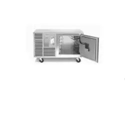
TBC5 (5-pan level undercounter model)
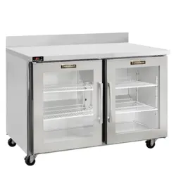
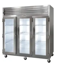
TBC13 (13-pan level reach-in model)
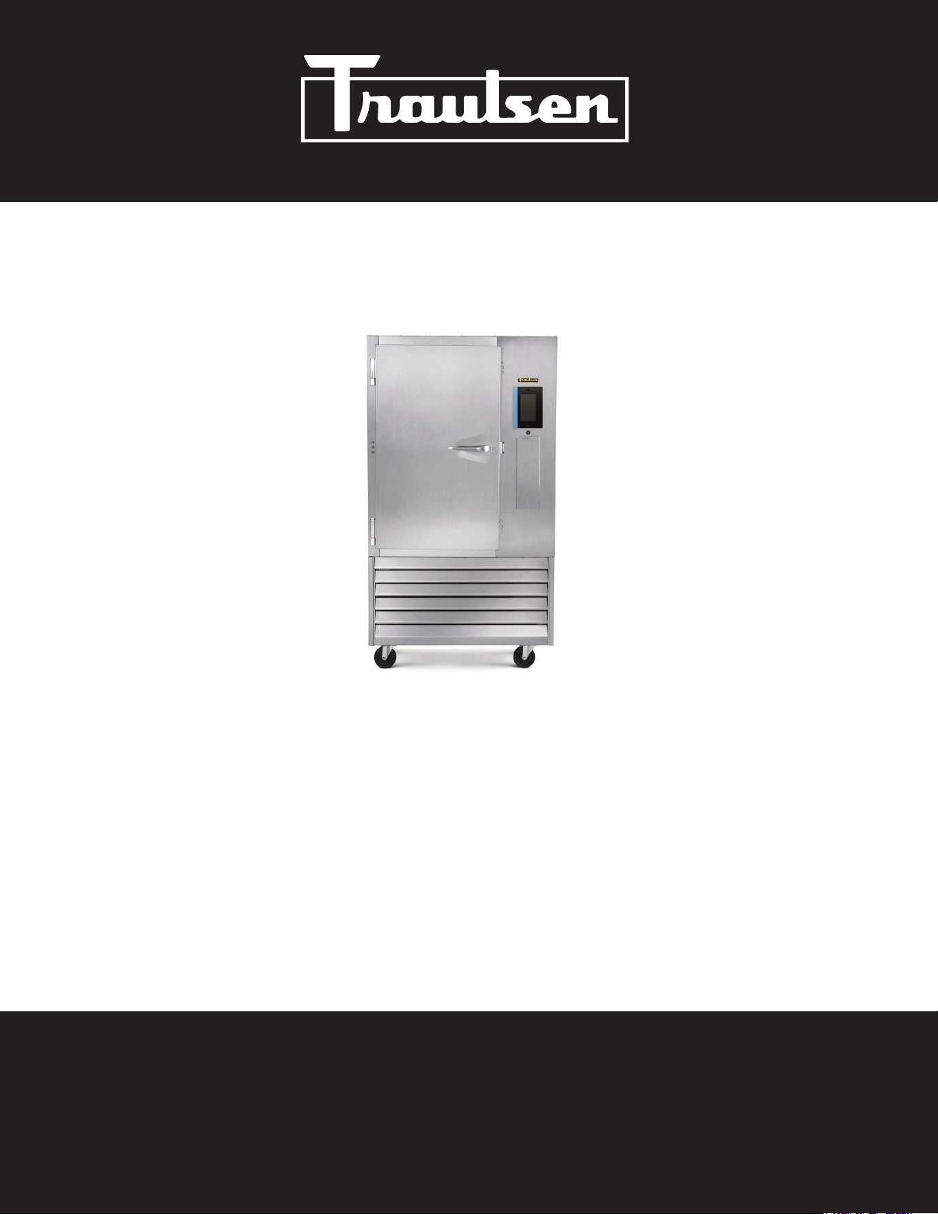
TBC1H (1-rack capacity roll-in model)
TBC1HR (1-rack capacity roll-thru model)
*For equipment produced after January 2026 only.
Hours Of Operation: Monday - Friday 7:30 a.m. - 4:30 p.m.
(CST)
4401 Blue Mound Road Fort Worth, Texas 76106 (USA)
Phone: 800.825.8220 | Service Fax: 817.740.6757 | E-mail: [email protected] | Website: traulsen.com
Quality Refrigeration
I. Table of Contents
II. Introduction
a-Overview Page 2
b-Basic Operation Page 2
c-Defrost Page 2
d-Installation Checklist Page 2
III. Receipt Inspection Page 3
IV. Installation
a-Location Page 3
b-Packaging Page 3
c-Wiring Diagram Page 3
d-Installing Legs or Casters Page 3
e-Interior Arrangements Page 4
f-Electrical Requirements/Cord & Plug Page 4
g-Proper Clearances Page 4
h-Condensate Removal Page 4
i-Remote Condensing Unit Requirements Page 4
j-Sealing Roll-In/Roll-Thru Units Page 5
k-ON/OFF Power Switch Page 5
l-Capacity Page 5
V. Care & Maintenance
a-Cleaning The Condenser Page 5
b-Cleaning the Exterior Page 5
e-Cleaning The Interior Page 5
VI. Other
a-TBC1H/TBC1HR Service Check & Start-Up Page 5
c-On-Site Blast Chill Training Page 5
d-Demonstrations Page 5
VII. Basic Operating Guidelines
a-Chilling Within HACCP Guidelines Page 6
b-Loading Page 6
c-Use of Food Probes Page 6
d-Covering Product Page 6
e-Multi-Batching Page 6
f-USB Port Page 7
g-Time Zones Page 7
h-Usernames Page 7
-1-
VIII. The Control
a-The Control-Overview Page 8
b-Modes of Operation Page 8
c-Operating Cycles Page 8
d-Programs Page 8
e-Auto Start Program Gallery Page 9
f-Quick Start Program Gallery Page 9
g-Create Program Page 10
IX. Operation
a-Auto Start Page 10
b-Quick Start Page 11
c-Manual Operation Page 11
d-Multi Operation Page 13
e-Adding Product to a Cycle in Progress Page 15
f-Cold Holding Page 15
g-Freezing Product Page 15
h-Defrosting Page 15
i-HACCP Page 16
j-Temperature Cycle Page 16
k-Time Cycle Page 17
l-Exported Data Page 17
m-Users Page 17
n-Products Page 18
o-Settings Page 18
p-General Management Page 19
q-Display Page 19
r-Printers Page 19
s-Supervisor Settings Page 20
t-Chilling & Installation Choices Page 20
u-Libraries & Data Page 20
X. Service/Warranty Information Page 21
XI. Troubleshooting Page 22
XII. TBC13 Condensate Kit Install Instructions Page 23
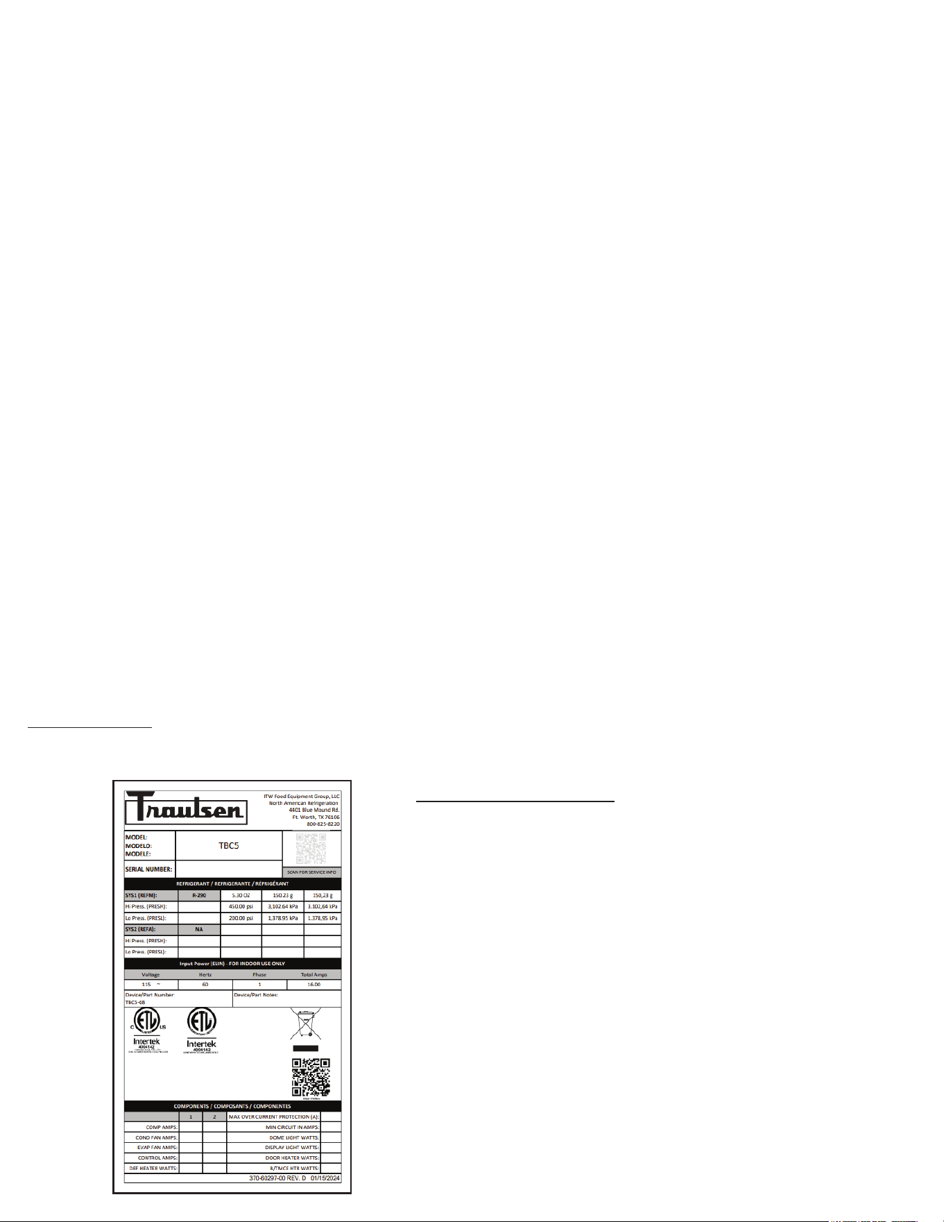
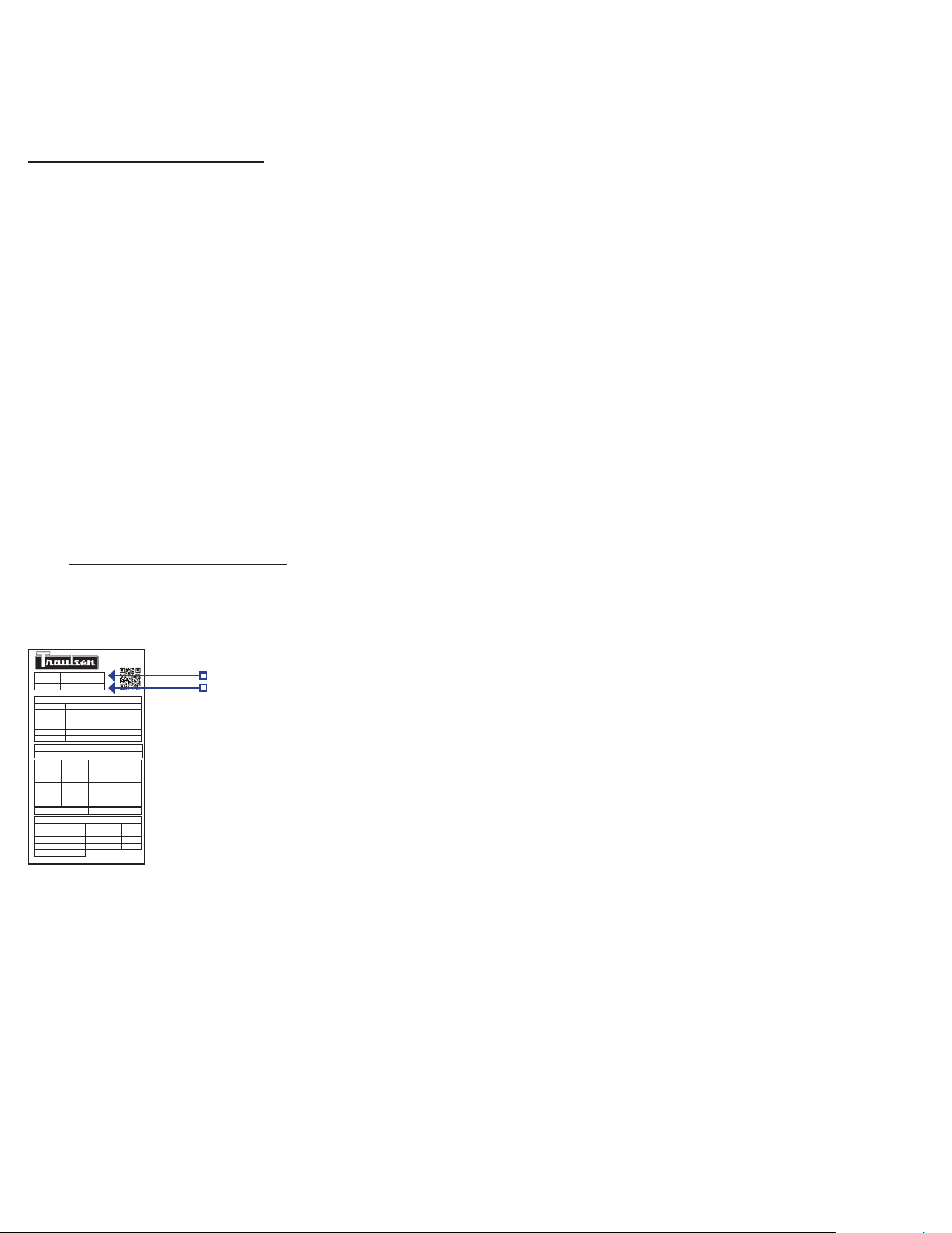
THE SERIAL TAG:
The serial tag is a permanently axed sticker on which is recorded vital electrical and refrigeration data about your Traulsen product,
as well as the model and serial number. This tag is located inside the door on the right interior wall of the cabinet.
READING THE SERIAL TAG
• Serial = The permanent ID# of your Traulsen
• Model = The model # of your Traulsen
• Volts = Voltage
• Hz = Cycle
• PH = Phase
• Total Current = Maximum amp draw
• Minimum Circuit = Minimum circuit ampacity
• Lights = Light wattage
• Heaters
• Refrigerant = Refrigerant type used
• Design Pressure = High & low side operating
pressures and refrigerant charge
• Agency Labels = Designates agency listings

II. Introduction
-2-
II. d - INSTALLATION CHECKLIST:
Install requirements vary by model...
Model TBC5
1) Insure proper clearances, no obstruction to either
front louver for at least 24” from cabinet face.
2) Install all four standard legs or optional casters,
insuring that the unit is level for proper operation.
3) Plug the power cord into a dedicated 115 volt, 20-amp
NEMA 5-20R outlet.
Model TBC13
1) Insure proper clearances. No obstruction of the front
louvers, 5-1/2" on the left, right and rear, and 12" above.
2) Install the legs or casters, insuring that the unit is
level for proper operation.
3) Place condensate tube in to oor drain or install
optional condensate evaporator.
4) Plug the power cord into a dedicated 208-230/60/1 volt, 20-
amp NEMA 6-20R outlet.
Models TBC1H & TBC1HR
1) Insure proper clearances. No obstruction to either front
louver, and for at least 12" above the cabinet. Unit must be
located on a level surface.
2) Seal the unit to the oor in accordance with local
sanitation codes.
3) Install the door ramp(s).
4) Place condensate tube into oor drain or install
optional condensate evaporator.
5) Plug the power cord into a dedicated 115 volt, 20-amp
NEMA 5-20R outlet.
IMPORTANT NOTES/WARNINGS
NOTE: In order to accomplish blast chilling, models TBC1H and
TBC1HR require one properly sized remote condensing unit.
This can be purchased from Traulsen or elsewhere, however
installation would be by others.
NOTE: This appliance is not intended for use by people (including
children) with reduced physical, sensory or mental capabilities, or
lack of experience and knowledge, unless they have been given
supervision or instruction concerning use of the appliance by a
person responsible for their safety.
NOTE: Children should be supervised to ensure that they do not
play with the appliance.
NOTE: The refrigerants for the partial units (for remote systems)
must comply with A1 classication requirements.
NOTE: The unit uses “VORACOR™ CR 1193 Polyol and VORA-
COR CE 108 Isocyanate is a two-component polyurethane foam
system expanded with HFO physical blowing agent 1233zd. This
product is designed for use in commercial refrigeration applica-
tions and is non-ammable.
NOTE: Appliance component parts requiring replacement should
only be replaced with like components so as to minimize the risk
of possible ignition due to incompatibility.
II. a - OVERVIEW:
It is important to note that although this product is designed to
chill hot product from 135°F down to below 41°F within FDA/
HACCP guidelines, several operational factors, such as product
temperature, density, loading, etc. will effect actual chilling
performance. As a result, although easy to use, the operation of
blast chilling requires diligent attention on the part of the operator(s)
in order to facilitate proper results.
It is also important to note that many perceived service problems
can actually be attributed to operational issues, resulting in lost
product and/or down time. Please review the instructions contained
within this manual completely, and make certain that all operators
are well trained in the equipment’s proper use.
II. b - BASIC OPERATION:
All Traulsen blast chillers accomplish their task by rapidly circulating
very cold air. Upon starting a chill cycle using the STANDARD
method, interior cabinet air temperature is set to a -27°F dierential
from the target temperature. When using the default target of 37°F
the chiller will cycle between 10°F (OFF) and 15°F (ON). These
temps were determined as optimum for rapid chilling product
without freezing.
NOTE: For products prone to freezing (ex. high water content
such as produce) we recommend use of the DELICATE method.
Delicate uses a dierential of only -7°F from the target temperature.
The blast chiller will continue this operation until such time as all
probes reach the target temperature (when chilling by TEMP) or all
time zones have elapsed (when chilling by TIME). At this point it
will automatically return to MAINTENANCE operation with cabinet
air temperature maintained at the target temperature (default
37°F). This maintains chilled food safely refrigerated and in the
case of FREEZE cycles, the product will be held at the correct
frozen temperature.
II. c - DEFROST:
All refrigeration equipment require a regular defrost cycle in order
to maintain their evaporator coils clear of ice. The Traulsen blast
chillers covered in this manual are programmed to automatically
defrost every (4) four hours.
The period of defrost will be a maximum of 30 minutes in duration
(DefrostMaxTime + DefrostWaitTime + RecoveryMax). This
is temperature terminated. Should the coils reach their target
temperature of 50°F prior to that time elapsing, the blast chiller
will automatically stop defrosting and return to normal operation.
Product left inside will be safely held because:
a) If occurring at the end of a chill cycle the cabinet air temp of
10-15°F will hold the product safely for the maximum 30 minutes
of defrost.
b) If occurring while in maintenance mode the defrost period will
almost certainly be signicantly less than 30 minutes, so product
temperature will not be eected.
NOTE: Do not open the door during defrost unless removing all
product inside.

WARNING
-3-
II. Introduction (continued)
NOTE: The appliance is to be installed in accordance with the
Safety Standard for Refrigeration Systems, ANSI/ASHRAE 15.
NOTE: The appliance is intended for use at altitudes below
2000 m.
NOTE: Blast Chillers are classied for operation at climate class 5.
Climate Class 5 refrigeration equipment is suitable for harsher
conditions and includes equipment that can eciently handle
temperatures up to +40°C (104°F) and humidity up to 40% RH.
These refrigeration units are ideal for use in commercial kitchens,
warehouses, distribution centers, and specialty food retailers
where maintaining consistent temperature is crucial. They are
equipped with high-performance compressors and strong insula-
tion to ensure optimal cooling performance in high-temperature
environments.
WARNING: For partial units, do not exceed low side design
pressure specied on the data plate.
WARNING: Do not store explosive substances such as aerosol
cans with a ammable propellant in this appliance.
WARNING: Do not use electrical appliances inside the food
storage compartments.
DANGER: Risk of re or explosion. To be repaired only by trained
service personnel. Do not puncture refrigerant tubing. Consult
repair manual/owner’s guide before attempting to service this
product. All safety precautions must be followed. Dispose of
properly in accordance with federal or local regulations.
III. Receipt Inspection
All Traulsen products are factory tested for performance and
are free from defects when shipped. The utmost care has been
taken in crating this product to protect against damage in transit.
All interior ttings have been carefully secured and the legs or
casters are boxed and strapped inside to prevent damage. Door
keys will be attached to the handle with a nylon strip. The handle
is protected by an easily removable nylon netting.
You should carefully inspect your Traulsen unit for damage during
delivery. If damage is detected, you should save all the crating
materials and make note on the carrier’s Bill Of Lading describ-
ing the damage. A freight claim should be led immediately. If
damage is subsequently noted during or immediately after in-
stallation, contact the respective carrier and le a freight claim.
There is a ve (5) day limit to le freight damage with the carrier.
Under no condition may a damaged unit be returned to Traulsen
without rst obtaining written permission (return authorization).
You may contact Hobart/Traulsen customer care at 800-333-7447
to request a return.
Systems Using Refrigerant R-290 (Propane)
Traulsen has selected propane as the refrigerant for many of
their products. In addition to its low global warming potential and
impact on the environment, propane is an ideal refrigerant. It is
a ammable refrigerant, however, which is why you will see a
“ammable refrigerant” sticker on applicable products. Traulsen
products using propane as the refrigerant are ETL approved
and are safe to use in accordance with this Owner’s Manual and
general industry practices for commercial cooking environments.
Please check with local codes or regulations for any restrictions
to products using hydrocarbon refrigerants.
IV. Installation
IV. a - LOCATION:
Select a proper location for your Traulsen unit, away from extreme
heat or cold. Allow enough clearance between the unit and the
side wall so that the door(s) may open a minimum of 90°.
NOTE: The appliance shall not be installed in public corridors
or lobbies.
IV. b - PACKAGING:
All Traulsen units are shipped from the factory bolted to a sturdy
wooden pallet and durably packaged. Care should be taken
when removing the packaging in order to avoid scratching the
unit’s exterior metal nish.
To remove the wooden pallet, rst if at all possible, we suggest
that the cabinet remain bolted to the pallet during all transportation
to the point of nal installation. The bolts can then be removed
with a 3/4” socket wrench.
NOTE: DO NOT LAY THE UNIT ON ITS SIDE DURING
TRANSPORTATION OR INSTALLATION.
IV. c - WIRING DIAGRAM:
Refer to the wiring diagram located on the rear of the cabinet for
any service work performed on the unit. Should you require a wir-
ing diagram, please contact Traulsen Service at (800) 825-8220,
and provide the model and serial number of the unit involved.
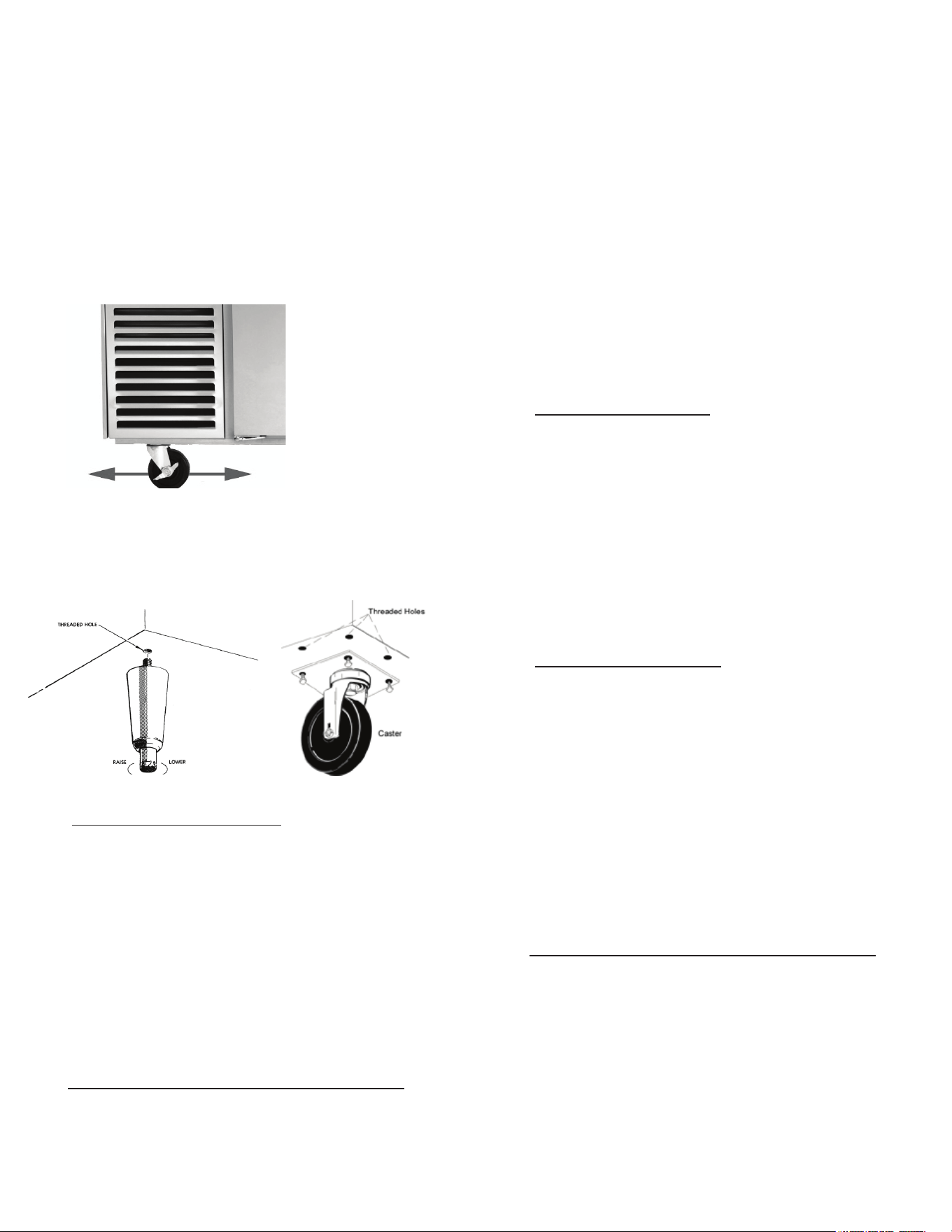
IV. d - INSTALLING LEGS OR CASTERS:
The cabinet must be blocked and stable before
installing legs or casters.
6” high stainless steel legs are supplied standard for models
TBC5 and TBC13. Casters in lieu of legs are available as an
optional accessory for the same models. These are shipped from
the factory packed inside a cardboard box which is strapped to
one of the shelves. Remove the nylon strap and open the box,
it should contain either four (4) legs or casters (and four bolts
for each caster).
To install the legs or casters, rst raise and block the unit a mini-
mum of 7” from the oor.
For model TBC5 slide the legs or casters into the two channels
under the front and back of the cabinet (see g. 1). Secure in
place by tightening the two bolts located at the base of each leg
or caster.
For your safety and protection, all units supplied with a cord and
plug include a special three-prong grounding plug on the service
cord. Select only a certied electrical outlet with grounding plug
for power source. For TBC1H/R, cabinet is cord-connected and
there is no electrical connection or control wiring between from
cabinet to the remote condensing unit.
NOTE: Do not under any circumstances, cut or remove the round
grounding prong from the plug, or use an extension cord.
A dedicated, grounded circuit should be provided to assure that
the computerized control is not adversely aected by the opera-
tion of other equipment.
Models TBC5, TBC1H, and TBC1HR are provided with a NEMA
5-20P cordset.
Model TBC13 is provided with a NEMA 6-20P cordset.
IV. g - PROPER CLEARANCES:
Model TBC5: Insure proper clearances. No obstruction to either
front louver for at least 24" from cabinet face.
Model TBC13: Insure proper clearances. No obstruction of the
front louvers, 5-1/2" on the left, right and rear, and 12" above.
This will allow for sucient air ow to the refrigeration system
and maintenance access.
Models TBC1H and TBC1HR: Insure proper clearances. No
obstruction to either front louver, and for at least 12" above the
cabinet. Unit must be located on a level surface. This will allow
for sucient airow to the refrigeration system and maintenance
access.
IV. h - CONDENSATE REMOVAL:
All Traulsen Blast Chill models (except model TBC5) require the
use of a oor drain or optional electric condensate evaporator.
Model TBC13 requires either a oor drain or the use of an op-
tional bottom mounted electric condensate evaporator pan kit
(TBCACC-BMCE) for condensate removal. The drain port loca-
tion is at the bottom right of the unit. A receptacle is provided
underneath. See the back cover of this manual for installation
instructions.
Models TBC1H and TBC1HR require either a oor drain or
the use of an optional electric condensate evaporator pan kit
(BCACC-60018) for condensate removal. This can be installed
on the chiller through the access panel located front right at the
bottom.
IV. i - REMOTE CONDENSING UNIT REQUIREMENTS:
For TBC1H and TBC1HR: Remote condensing unit(s) capacity
requirement: 18,700 BTU/hr @ 0°f evaporator temperature
(supplied by others).
Fig. 1
-4-
IV. Installation (continued)
NOTE: Legs or casters must be installed towards the four
corners of the unit for proper support.
On model TBC13 thread the legs into the threaded holes on the
bottom of the cabinet (see g. 2). Be certain that all legs are
tightened securely. When the unit is set in its nal position, it is
important for proper operation that the unit be level. The legs are
adjustable for this purpose, turn the bottom of the leg counter-
clockwise to raise it, clockwise to lower it. Level the unit from
front to back as well as side to side in this manner, using a level
placed in the bottom of the cabinet.
For installing optional casters, these are “plate” type, and require
the use of four (4) bolts to secure them rmly to the cabinet bot-
tom at each corner (see g. 3). The caster bolts are tightened
using a 1/2” socket wrench.
IV. e - INTERIOR ARRANGEMENTS:
Models TBC5 and TBC13 are shipped with their full compliment
of trayslides already installed from the factory. Upon delivery
the plastic ties used to secure these during shipping should be
removed prior to rst use.
The slides are spaced to allow for maximum capacity of 2” deep
pans. If use of deeper pans is required, the slides can be removed
and adjusted to accommodate this. However please note that the
total quantity of pans possible will be reduced in order to make
room for the deeper pans.
Model TBC1H and TBC1HR are designed to accommodate one
roll-in rack with overall dimension (wheels inboard of frame) which
do not exceed 72” high by 27” wide by 29” deep.
IV. f - ELECTRICAL REQUIREMENTS/CORD & PLUG:
Traulsen models TBC5, TBC13, TBC1H, and TBC1HR are
supplied with a cord & plug attached. A remote condensing unit
(supplied by others) will require a separate electrical connection
of its own.
Fig. 2
Fig. 3

IV. j - SEALING ROLL-IN/ROLL-THRU UNITS:
This section applies only to models TBC1H and TBC1HR. Roll-In
and Roll-Thru cabinets set on the oor require the oor area to
be at and level. In addition, after the cabinet is set in place, seal-
ant should be used around the perimeter of the base to comply
with NSF International requirements. After sealing the unit, the
enclosed ramp should then be installed.
IV. k - ON/OFF POWER SWITCH:
The Traulsen Blast Chiller models are all equipped with a power
ON/OFF switch intended to cut power to the control as needed.
In the event of routine maintenance and/or service is needed,
be certain to disconnect the electrical power to the machine and
follow lockout/tagout procedures.
This is located on top of models TBC1H, towards the rear on
top. On model TBC5, this switch is located in the compressor
compartment. On model TBC13 this is located on the bottom
right behind the front louver assembly.
IV. l - CAPACITY:
Pan and approximate maximum product weight capacities for
the individual blast chiller models is as follows:
Pans Product
18” x 26” 12” x 20” Weight
• TBC5 5 10 100
• TBC13 13 26 200
• TBC1H 1 Rack 1 Rack 300
Actual capacity (i.e. weight of product) that can be safely chilled
within FDA guidelines varies greatly depending upon individual
product density and pan loading.
V. Care & Maintenance
Disconnect electrical power supply before
cleaning any parts of the unit.
V. a - CLEANING THE CONDENSER:
The most important thing you can do to ensure a long, reliable
service life for your Traulsen is to regularly clean the condenser
coil. The self-contained condensing unit requires regularly
scheduled cleaning to keep the nned condenser clean of lint
and dust accumulation. Keeping the condenser clean allows the
cabinet to operate more eciently and use less energy.
To clean the self-contained condenser, rst disconnect electrical
power. To access the coil:
TBC5: Open the refrigeration compartment door on left.
TBC13: Remove the four (4) screws securing the front louver
panel at bottom and remove the panel.
TBC1H/TBC1HR: Remove the two (2) bottom screws securing
the louver assembly located on the top/front of the cabinet and
lift the louvers.
Vacuum or brush any dirt, lint or dust from the nned condenser
coil, the compressor and other cooling system parts. If signicant
dirt is clogging the condenser ns, use compressed air to blow
this clear.
IV. Installation (continued)
-5-
For care of the remote condensing unit(s) used for models TBC1H
& TBC1HR, consult the manufacturer’s product literature.
Remove any ignition source (arc, ame, heat) before cleaning the
condenser coil. If the condenser coil is inadvertently damaged
during cleaning to the point of causing a refrigerant leak,
immediately ventilate the area and call for service.
V. b - CLEANING THE EXTERIOR:
Exterior stainless steel should be cleaned with warm water, mild
soap and a soft cloth. Apply with a dampened cloth and wipe in
the direction of the metal grain. Avoid the use of strong deter-
gents and gritty, abrasive cleaners as they may tend to mar and
scratch the surface.
Do NOT use cleansers containing chlorine, this may
promote corrosion of the stainless steel.
Care should also be taken to avoid splashing the unit with water,
containing chlorinated cleansers, when mopping the oor around
the unit. For stubborn odor spills, use baking soda and water
(mixed to a 1 TBSP baking soda to 1 pint water ratio).
V. c - CLEANING THE INTERIOR:
For cleaning stainless steel interiors, the use of baking soda as
described in section “V. b” is recommended. Use on breaker
strips as well as door gaskets. All interior ttings are removable
without tools to facilitate cleaning.
Only TBC13 models have a cabinet drain plug. Do
NOT spray the TBC13 interior with a hose to clean. Care should
be taken to avoid splashing of water in the unit's interior.
Please make sure the drain plug is in place at all times except
while cleaning. Ensure that the cabinet drain is routed to the near-
est oor drain. If the oor drain is not available, use conventional
methods to wipe the interior clean (do not use cabinet drain).
VI. Other
VI. a - TBC1H/TBC1HR SERVICE CHECK & START-UP:
After installation and start-up of models TBC1H or TBC1HR,
please contact the Service Department at (800) 825-8220 to
arrange for a “Mechanical Installation and Operation Inspection,”
which is required by Traulsen in order to validate the warranty.
On-site inspection not required for models TBC5 and TBC13.
VI. b - ON-SITE BLAST CHILL TRAINING:
Traulsen oers the operator comprehensive one and two day,
onsite training in the proper operation of your Blast Chiller.
Contact your authorized Traulsen equipment dealer for pricing
information.
VI. c - DEMONSTRATIONS:
Traulsen sales representatives perform in-service operational
training for the end-user. Contact your local Traulsen Sales
Representative (after completion of the service agency start-up,
on required models) to arrange this.
WARNING
NOTICE
NOTICE
VII. a - CHILLING WITHIN HACCP GUIDELINES:
The current FDA Food Code allows much more time for safe
chilling than 90-minutes. This actually requires two critical
control points of:
a) From 135°F to 70°F within two hours, then...
b) From 70°F to below 41°F within four hours, for
a total chill time from 135°F to below 41°F of no
more than six hours.
Total chill time can exceed six-hours in duration and still be
safe. This safety threshhold does not include:
a) Any time needed for product to chill from any
start temp down to 135°F, or...
b) Any time elapsed to chill to below 41°F.
VII. b - LOADING:
To achieve quickest chill times product should be loaded to a
depth of no greater than 2”.
Products should always be loaded into the shallowest pan
possible.
Chilling of products of greater than 2” depth is often possible
within FDA guidelines. However please note that actual chill
times are a function of: Start Temperature, Product Density,
Product Depth, and Total Load.
Chilling of products, such as whole cooked chickens or meat-
loaf can be accomplished. However these should be positioned
inside the chiller to allow the airow to contact the greatest
surface area of the product.
VII. c - USE OF FOOD PROBES:
For most accurate results food probes should be used. These
need to be properly placed in the center of the thickest part of
the product to insure an accurate temperature reading.
Some products are not suitable for use of food probes. These
products...
a) Should be chilled by TIME.
b) The correct chill time should be established by
the operator based upon actual product testing.
c) The end cycle temperature should be veried
manually with a clean, accurate thermometer
as soon as the pre-established chill time elapses.
-6-
VII. d - COVERING PRODUCT:
Product does not always need to be covered. However before
doing so please consider the following potential scenarios...
a) If large loads of especially hot product are chilled
there is the potential to freeze the coil.
b) Loads of uncovered product that require
especially long chilling times may have the
potential to experience surface drying.
c) Loads that are left uncovered in the chiller for
long periods after completion of a chill cycle may
also experience surface drying of the product if
left uncovered.
d) Loads of especially liquid product, such as soup,
are highly recommended to be covered in order
to prevent accidental spillage.
e) Some foods, such as rice and pasta, are
particularly vulnerable to drying and so
should always be covered.
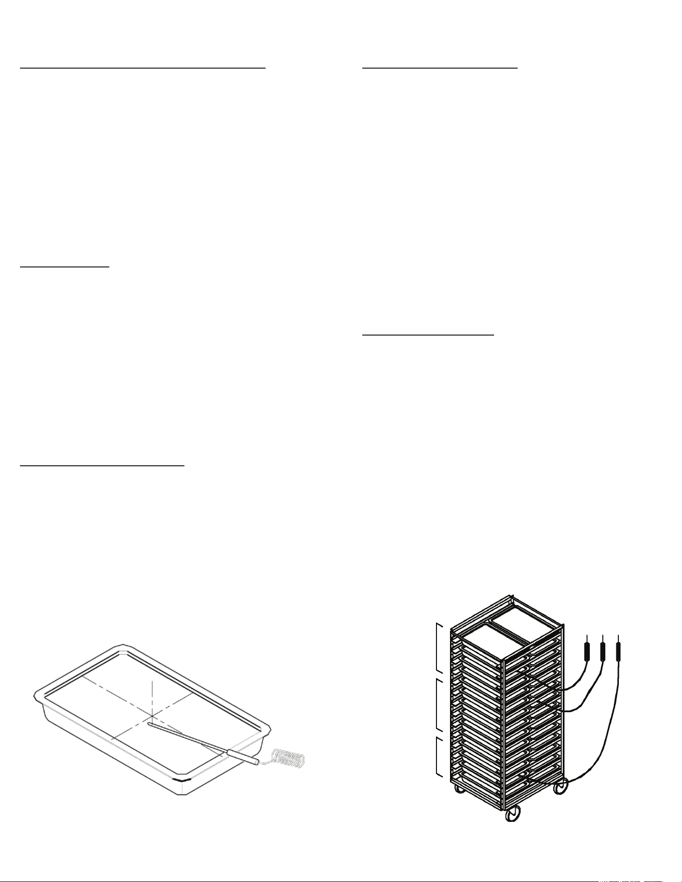
VII. e - MULTI-BATCHING:
Often an operator may wish to chill less than a full load of prod-
uct, and/or to chill multiple types of products simultaneously,
or at dierent intervals. This is known as “Multi-Batching.”
In a multi-batching scenario it is critically important to man-
age the use of probes. For example if more than four dierent
products need to be chilled, it is necessary to take the following
into consideration:
• Like products should be grouped together in a single
batch using one probe.
• Dierent products, or products started at dierent times
should each have their own probe.
• If more than three products will ultimately be placed in
the chiller at the same or dierent times, it will be
necessary to: a) group like products together, or b)
group unlike products together with the probe placed in
the product which will take the longest to chill.
VII. Basic Operating Guidelines
Batch 1 Batch 2 Batch 3

VII. f - USB PORT:
A standard USB data port is provided. This allows the operator to download chill cycle data on to a thumb drive for easy transfer to
a PC. It is also used to update the control’s operating software.
VII. g - TIME ZONES:
When chilling without probes the control allows for operation by an operator determined time. In the TIME program there is one time
zone provided which makes multi-batching possible. When using Multi Mode, up to ten time zones are provided.
Selecting a time zone permits entry of both a product and/or username, just as is done when using probes.
The zones are not specic to any location or number of pans in the chiller. The operator should determine how best to utilize these,
for example Zone 1 = Top, Zone 2 = Middle, etc.
VII. h - USERNAMES:
USER (i.e. operator) names can be programmed into the chiller memory using the SETTINGS PAGE. If a username is
selected at the beginning of a chill cycle it will appear under the USER icon on the RUN SCREEN, as well as on any
record for that chill cycle.
If no USER name is selected at the beginning of a chill cycle NO USER will appear under the USER icon on the RUN SCREEN,
as well as on any record for that chill cycle.
At the end of the chill cycle a USERNAME may be entered prior to pressing END. Tap the EDIT icon in the HACCP report to edit
the username.
-7-
VII. Basic Operating Guidelines (cont'd)
-8-
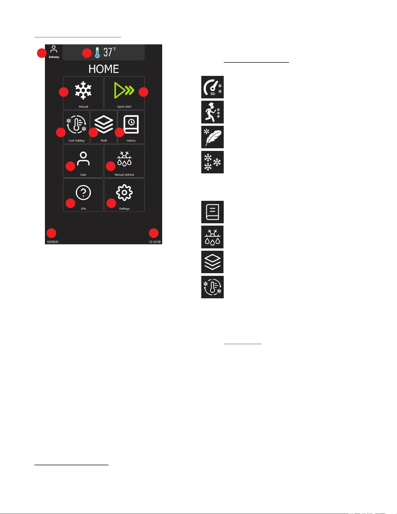
VIII. a - THE CONTROL - OVERVIEW:
1. Current active user.
2. Cabinet temperature (indicates defrost when applicable)
3. Manual Button: Tap to navigate to the manual chilling/
freezing page
4. Quick-Start Button: Tap to initiate a time-based blast
chilling cycle with one touch
5. Cold Holding Button: Tap to start a Cold Holding operation
to maintain food at a specic temperature
6. Multi Button: Tap to begin a Multi operation for
customized chilling needs
7. History Button: Tap to access the HACCP history page
8. Defrosting Button: Tap to start manual defrost operation
9. User Button: Tap to display and change the active user
10. Info Button: Access guides, key information
11. Settings Button: Tap to navigate to the settings page
12. Current date (MM:DD:YYY)
13. Current time (HH:MM:SS)
Traulsen blast chillers are equipped with our exclusive
NextGen control. This has a durable, water resistant, touch
screen interface for ease of use, and is surrounded by a heavy
gauge metal frame to protect it from damage.
The NextGen control can be used in one of two distinct
operating modes: AUTO or MANUAL.
VIII. b - MODES OF OPERATION:
The rst mode of operation is AUTO. This is designed to start a
chill cycle whenever one or more probes is placed into product
above 90°F, ensuring proper operation.
VIII. The Control
MANUAL is a fully adjustable mode which allows the operator to
select from a wide range of chill settings.
VIII. c - OPERATING CYCLES:
The control is capable of managing the following blast chilling cycles:
Standard temperature OR time-controlled blast chilling
Speed temperature OR time-controlled blast chilling
Delicate temperature OR time-controlled blast chilling
Temperature OR time-controlled blast freezing
In addition to blast chill cycles, the contol is also capable of
managing the following special cycles:
Programs with pre-dened cycles (how to chill)
Manual defrost
Multi operation: mixed operation with timers &
core probes
Cold holding: extra storage with wide temperature
setpoint range
NOTE: Blast freeze function is not available in TBC1H and
TBC1HR models.
VIII. d - PROGRAMS:
Programs are pre-installed chill settings designed to simplify and
optimize operation. These cater to various food types, portion
sizes, and cooling rquirements to support consistent and ecient
performance.
• Auto-Start: Using the food probe to activate a cycle
• Quick-Start: Using a simple touch to activate a cycle
• Manual: Applying a program to a manual operation
To change the programs, navigate to
Settings>Supervisor>Enter Password (1234)>Chilling &
Installation Choices
1 2
3 4
5 6 7
89
10 11
1213
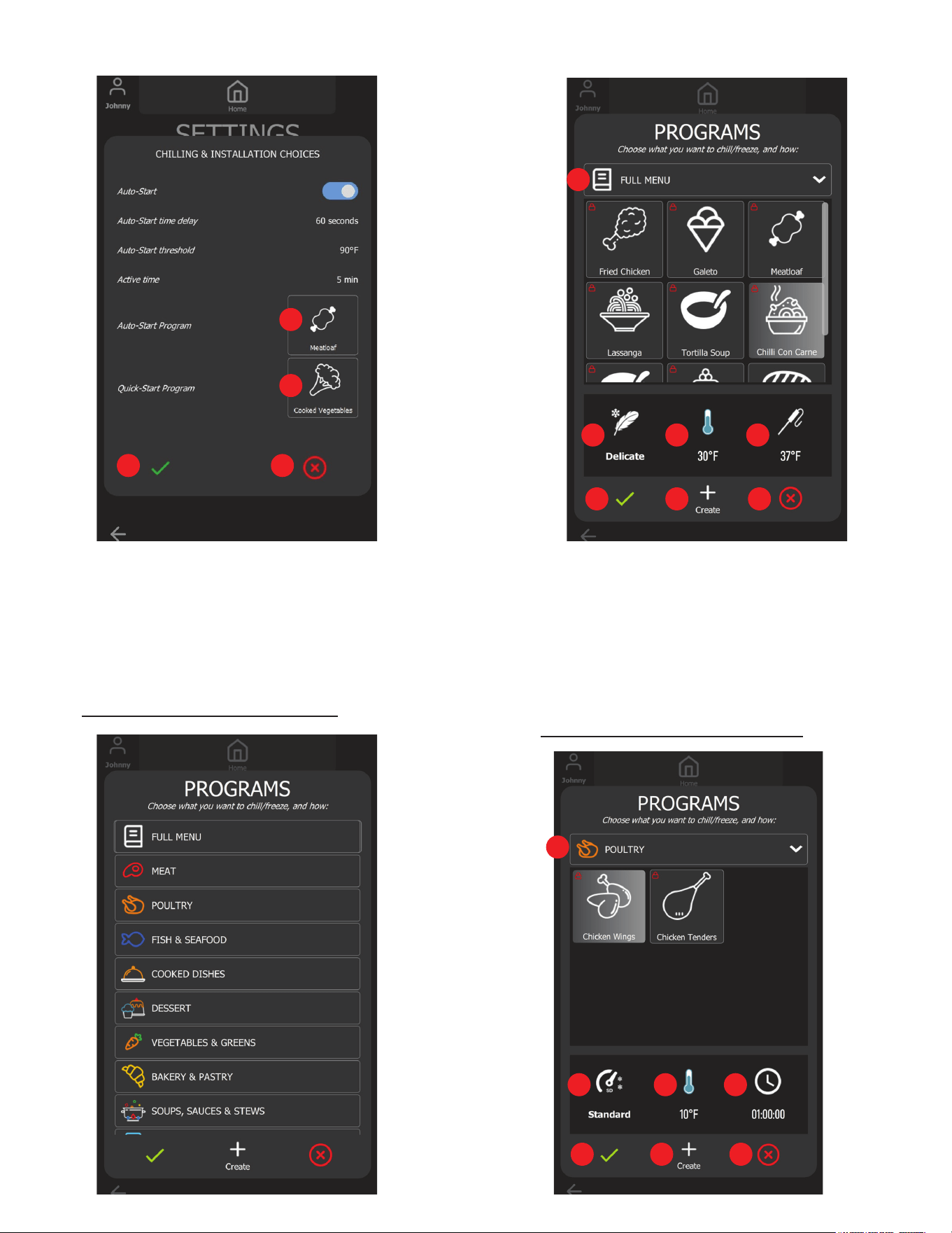
1. Quick-Start Program Button: Tap to display the Quick-Start
Program's Gallery and change the Quick-Start Program
2. Auto-Start Program Button: Tap to display the Auto-Start
Program's Gallery and change the Auto-Start Program
3. Accept Button: Tap to accept all changes and close
4. Cancel Button: Tap to discard all changes and close
VIII. e - AUTO START PROGRAM GALLERY:
-9-
1. Menu Button: Tap to change the category
2. Selected Auto-Start mode (Standard, Speed, or Delicate)
3. Selected Auto-Start air temperature setpoint
4. Selected Auto-Start target temperature
5. Accept Button: Tap to accept all changes and close
6. Create Button: Tap to create a program
7. Cancel Button: Tap to discard all changes and close
VIII. f - QUICK START PROGRAM GALLERY:
VIII. The Control (continued)
1
2
3 4
1
2 3 4
5 6 7
1
2 3 4
5 6 7
VIII. The Control (continued)
-10-
1. Menu Button: Tap to change the category
2. Selected Quick-Start mode
3. Selected Quick-Start air temperature setpoint
4. Selected Quick-Start cycle duration
5. Accept Button: Tap to accept all changes and close
6. Create Button: Tap to create a program
7. Cancel Button: Tap to discard all changes and close
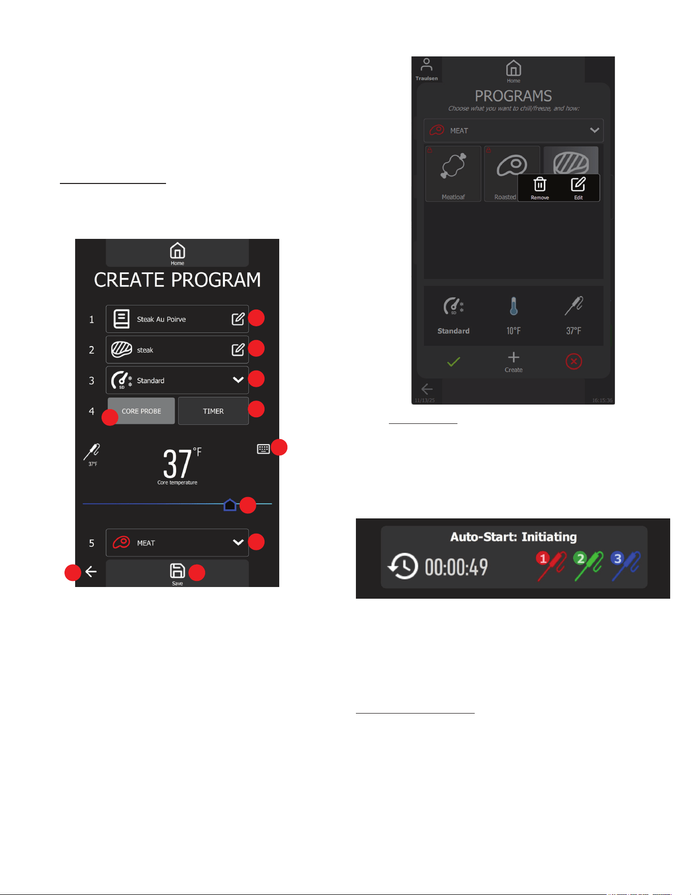
VIII. g - CREATE PROGRAM:
Users can create their own chill program to t their daily use. To
create a chill program, simply press the Create Button on the
programs gallery as shown in the gure above.
1. Program Name Input: Tap to enter the program name using
the virtual keyboard
2. Icon Select Button: Tap to select an icon for the Program
3. Chill Mode List: Select chill mode for the Program
4. Auto-Start Select Button: Tap to select temperature Program
5. Quick-Start Select Button: Tap to select timer Program
6. Keypad: Tap to turn on the keypad and change the time
temperature target value
7. Slider: Drag to adjust the core probe target temperature or
chill duration
8. Program Category: Tap to change the Program category
9. Save Button: Tap to save the Program settings
10. Return Button: Tap to discard and return to the home page
Users can remove or edit the created programs (default programs
cannot be removed or edited) directly by pressing and holding
the program on the list.
IX. a - AUTO START:
The default Auto Start Program is set to Standard function with a
target temperature of 37°F, but it can be modied in the Programs
menu. Auto Start is activated when the user is not using the user
interface and after inserting core probe/probes into the hot food.
When conditions are met, a dialog box will automatically pop up
on the home page.
NOTE: Food must be above 90°F in order to AUTO start.
When adding probes to a chill cycle already in process simply
place any available probe into hot product above 90°F and these
will be automatically added. NOTE: The operator can edit the
user and/or product name during chilling and/or at the cycle end.
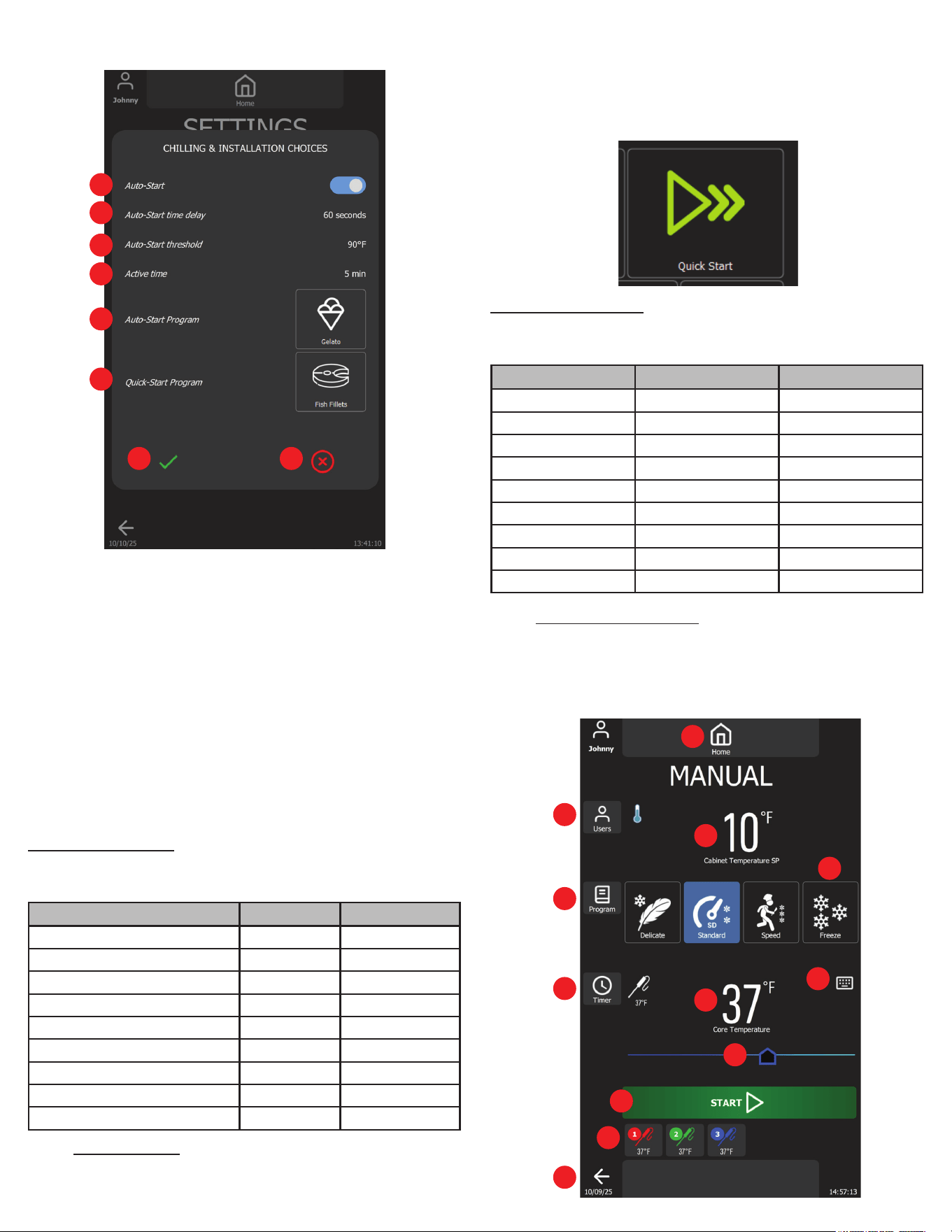
Customizing Auto-Start:
Auto-Start's settings can be customized by accessing the Setings
Page>Supervisor>Chilling & Installation Choices.
1
2
3
4
5
6
7
8
910
IX. Operation
-11-
1. Auto-Start Switch: Enable or disable the feature
2. Auto-Start Time Delay Button: Tap to turn on the virtual keypad
to change the countdown timer until the blast chill cycle starts
automatically
3. Auto-Start Threshold Button: Tap to turn on the virtual
keypad to change the temperature threshold to trigger
auto-start countdown
4. Active Time Button: Tap to turn on the virtual keypad to change
the time to switch back to Home Page and to trigger auto-start
5. Auto-Start Program: Tap to change the auto-start program
6. Quick-Start Program: Tap to change the quick-start program
7. Accept Button: Tap to save all changes and close
8. Cancel Button: Tap to discard all changes and close
Auto-Start Programs:
The NextGen Blast Chiller comes equipped with some default
programs, illustrated below.
IX. b - QUICK START:
Quick Start is a user-friendly feature that allows you to instantly
begin a time-controlled blast chill cycle with a single press on the
home screen. Designed for convenience, it streamlines daily use
by eliminating the need to navigate multiple options.
Quick Start Programs:
The NextGen Blast Chiller comes equipped with some default
programs, illustrated below.
IX. c - MANUAL OPERATION:
MANUAL mode allows adjustments to be made to all chilling
parameters, thus customizing the cycle to best suit the product
and/or process. Navigate to the manual page by pressing the
"Manual" button on the Home Page.
IX. Operation (continued)
1
2
3
4
5
6
7 8
1
2
3
4
5
6
7
8
9
10
11
12
Name Function Target
Standard 37°F
Fried Chicken Standard 37°F
Gelato Freeze 0°F
Meatloaf Standard 37°F
Lasagna Standard 34°F
Tortilla Soup Standard 32°F
Chilli Con Carne Delicate 37°F
Cream-Based Sauces & Soups Delicate 37°F
Custards & Puddings Delicate 37°F
Name Function Target
Standard 01:30:00
Chicken Wings Standard 01:00:00
Sandwich Delicate 00:10:00
Chicken Tenders Standard 01:30:00
Roasted Beef Speed 04:00:00
Cooked Shrimps Delicate 01:00:00
Fish Fillets Delicate 01:30:00
Chopped Vegetables Delicate 00:20:00
Cooked Vegetables Delicate 00:30:00
IX. Operation (continued)
1. User Button: Tap to change the active username
2. Program Button: Tap to apply the program to the current
manual cycle
3. Timer/Core Probe Button: Tap to switch between
temperature-based or time-based cycle
4. Mode List: Manual Mode selection
5. Keypad: Tap to turn on the virtual keypad to change the
target temperature setpoint (temp-based cycle)
6. Slider: Drag to change the target temperature setpoint
(temp-controlled cycle)
7. Start Button: Tap to start the cycle
8. Core Probes List: Core probe selection list
9. Return Button: Tap to return to home page
10. Cabinet temperature setpoint display
11. Core probe target temperature setpoint display
(temp-controlled cycle)
12. Home Button: Tap to return to home page
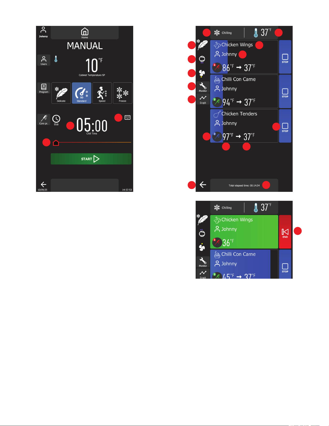
13. Total cycle time display (time-controlled cycle)
14. Slider: Drag to change the cycle time (time-controlled cycle)
15. Keypad: Tap to turn on the virtual keypad to change the
operation time (time-controlled cycle)
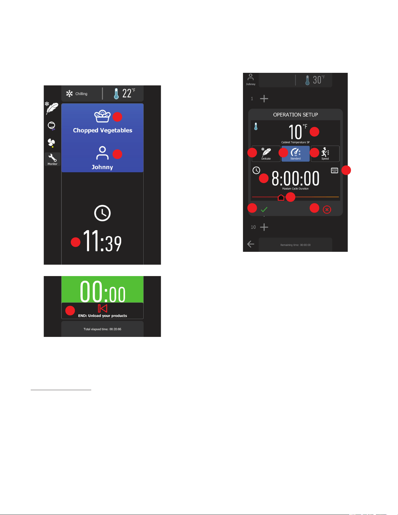
After the temperature-based cycle has been initiated with the
three food probes selected, the following page will appear.
1. Control state status
2. Real-time cabinet temperature
3. Selected chill mode
4. Compressor status (each dot represents the number of
compressors running)
5. Cabinet fan status (red means high speed and yellow means
low speed)
6. Monitor Button: Tap to turn on real-time system monitor
7. Graph Button: Tap to turn on graph view
8. Product name, tap to change
9. User name, tap to change
10. Core probe number
11. Core probe temperature
12. Target temperature
13. Control Button: Tap to stop monitoring corresponding core
probe
14. Total elapsed time
3
4
5
6
7
13
14
15
15
1 2
8
9
10
11 12
13
14
16
-12-
-13-
Once each product meets the desired requirements, its HACCP
information is automatically recorded in the history database.
Upon entering the Multi page, the cycle selection will be displayed.
The user must select a cycle before starting the chilling process.
1. Cabinet temperature setpoint
2. Speed Mode maintains cabinet temperature between 0°F
and 5°F
3. Standard Mode maintains the cabinet temperature between
10°Fand 15°F
4. Delicate Mode maintains the cabinet temperature between
30°F and 35°F
5. Keypad: Tap to modify the cycle duration
6. Cycle duration
7. Slider: Drag to modify the cycle duration
8. Accept Button: Tap to start chilling
9. Cancel Button: Tap to exit and return to Home Page
When users select Chill Mode and press the Accept button, the
chill cycle begins, and the following page will be displayed.
IX. Operation (continued)
15. Return Button: Tap to return to Home Page
16. Control Button: Tap to end the cycle and HACCP record will
display
After the time-based cycle has been initiated with the selected
duration, the following page will appear.
1. Product display, tap to change the product name
2. User display
3. The remaining blast chill time
4. Control Button: Tap to end the blast chill cycle
IX. d - MULTI OPERATION:
The multi-mode is designed to provide maximum exibility for
kitchens handling a variety of dishes simultaneously. This allows
the user to chill multiple types of food with dierent sizes, textures,
and cooling requirements all in one cycle.
Using timer and core probes, the system monitors and adjusts
chilling parameters to ensure each product reaches its optimal
temperature without compromising quality. This mode is ideal for
a la carte service environment where individual portions need to
be quickly and eciently chilled to meet food safety standards
while preserving taste, texture, and appearance.
1
2
3
4
4
1
2 3
5
6
7
8 9
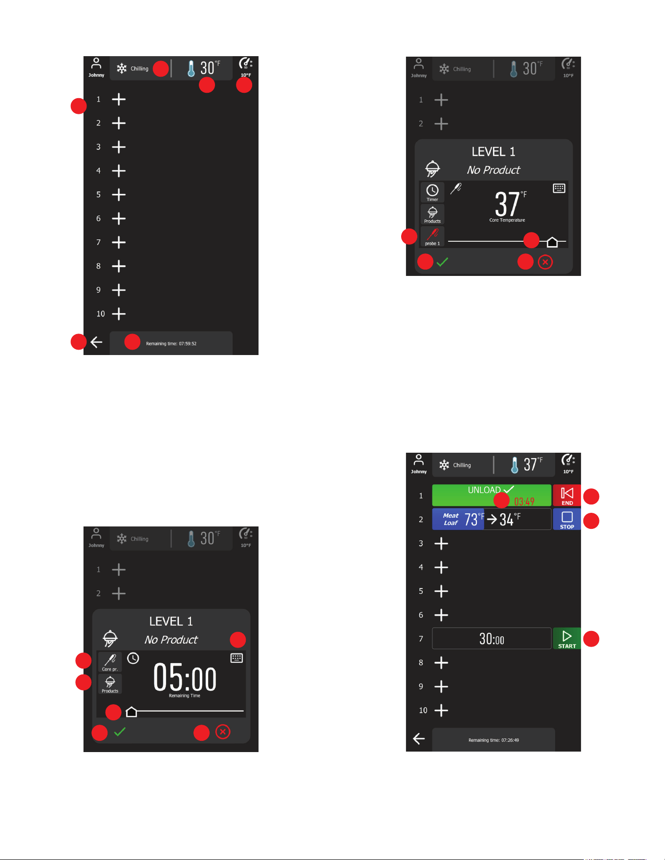
1. Level Setup Buttons: Tap to turn on the level setup dialog
2. Control state status
3. Cabinet teperature
4. Selected chill mode and cabinet temperature setpoint
5. Cancel Button: Tap to cancel the operation and return to Home
Page
6. Total chill time
Users can select any level to start the timer or use the food probe
to monitor the product by simply pressing the plus icon, then the
tray setup will appear.
1
2
3 4
5 6
1
1
2
3
3
4
4
7 8
1. Toggle Button: Tap to switch between timer or core probe
control.
2. Products Button: Turn on the product list and select product
name for chilling.
3. Slider: Drag to change the cycle duration of the chosen level.
4. Keypad: Tap to turn on the virtual keypad to enter the cycle
duration time of the chosen level.
5. Probe Selection Button: Tap to open the available core probes
list to select.
6. Slider: Drag to change the core probe target temperature.
7. Accept Button: Tap to accept the level setup.
8. Cancel Button: Tap to discard all setups or changes.
1. End Button: Cycle is complete, tap to end & save HACCP
data
2. Overtime Counter: Product needs to be removed
3. Stop Button: Tap to cancel the ongoing cycle
5
6
7 8
2
-14-
IX. Operation (continued)
-15-
4. Start Button: Tap to start the timer/measure probe
IX. e - ADDING PRODUCT TO A CYCLE IN PROGRESS:
Additional products can be added to chill cycles already in progress
when using either the AUTO or MANUAL mode.
For cycles started using either AUTO or MANUAL, simply insert
an available probe into the new hot product to be added. The
chiller will automatically add this probe to the cycle.
This can be repeated as long as there remains an available probe
or zone to use with the new product.
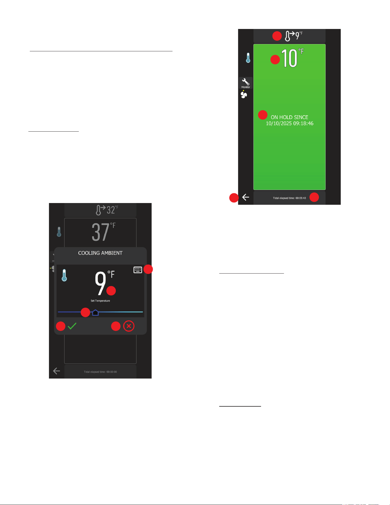
IX. f - COLD HOLDING:
This is a refrigeration cycle of innite duration that can precede
all the operating cycles.
To initiate Cold Holding, simply press the Cold Holding button
on the Home Screen.
Upon entering the Cold Holding page, users are required to set the
cabinet temperature set point to hold the food at the temperature.
Use the slider or press the keypad to set the holding temperature.
1. Keypad: Tap to turn on the virtual keypad for setting the cabinet
temperature
2. Cabinet setpoint
3. Temperature Slider: Drag to adjust the cabinet settings
4. Accept Button: Tap to initiate the cold holding mode
5. Cancel Button: Tap to go back to the Home Page
When users press the Accept button, the Cold Holding cycle
begins, and the following page will be displayed.
1. Current cabinet temperature setpoint
2. Real-time cabinet temperature
3. Cycle start time
4. Elapsed cycle duration
5. Cancel Button: Option to cancel Cold Holding and return to
the Home page.
IX. g - FREEZING PRODUCT:
Freezing is done using the MANUAL mode. From the MANUAL
programming screen...
1) Begin by inserting a probe into the product(s) to
be frozen.
2) Press MANUAL then TEMP.
3) Adjust SETTINGS to desired target temp.
4) Select METHOD if other than STANDARD is needed.
5) Select active PROBE. Add operator and product
name if desired.
6) Press START.
NOTE: Upon cycle completion the chiller will automatically enter
“Maintenance Mode” where temperature is held between 0°F and
5°F after the blast freezing cycle
.
IX. h - DEFROSTING:
A defrosting cycle can be initiated manually by pressing the
Defrost Button on the Home Page, followed by the Start Button.
A defrost cycle can be started manually or automatically based
on the 4-hour interval.
An automatic defrost cycle may occur during a Holding, Chilling
cycle or Freezing cycle to ensure the evaporator coil remains
clear and free of frost buildup.
1
2
3
4 5
1
2
3
4
5
IX. Operation (continued)
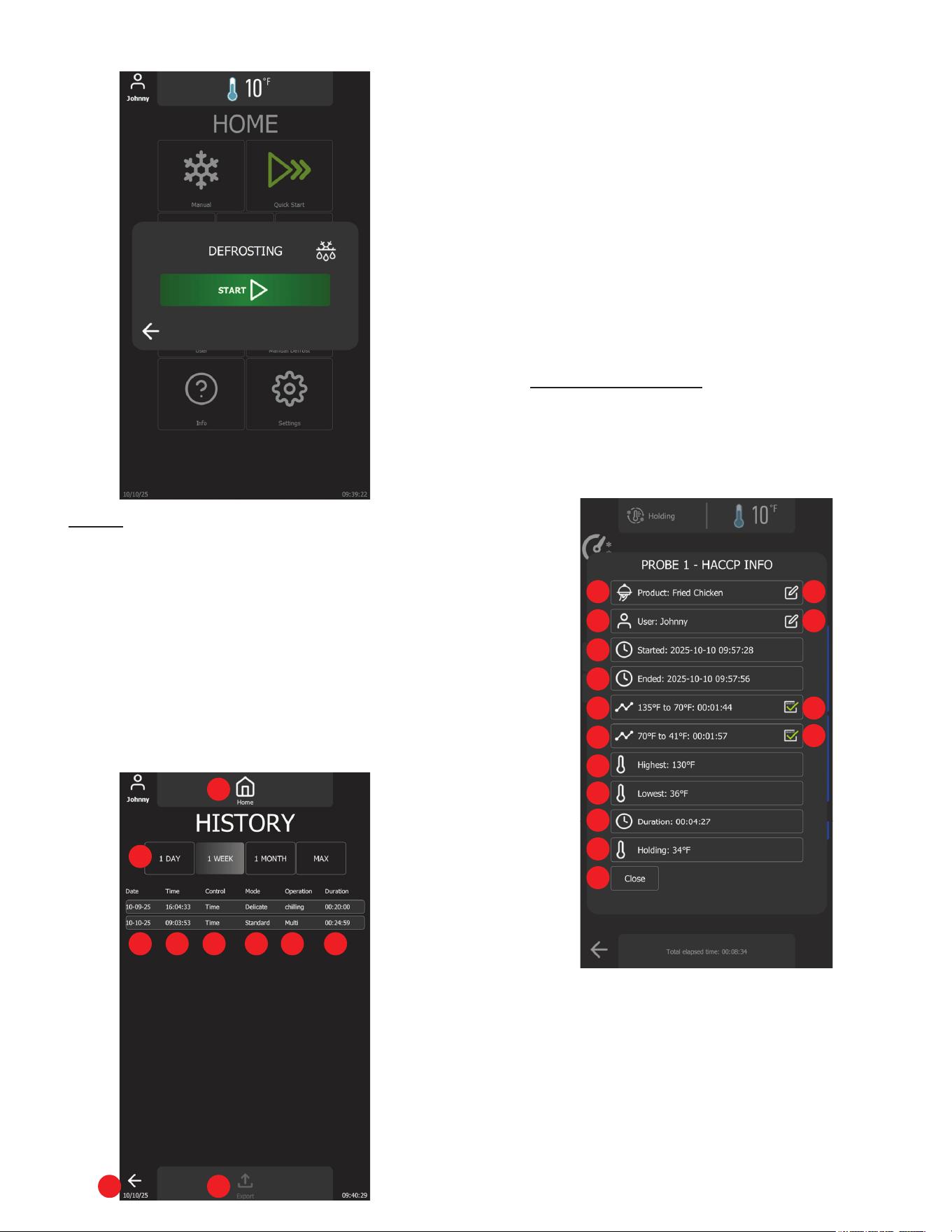
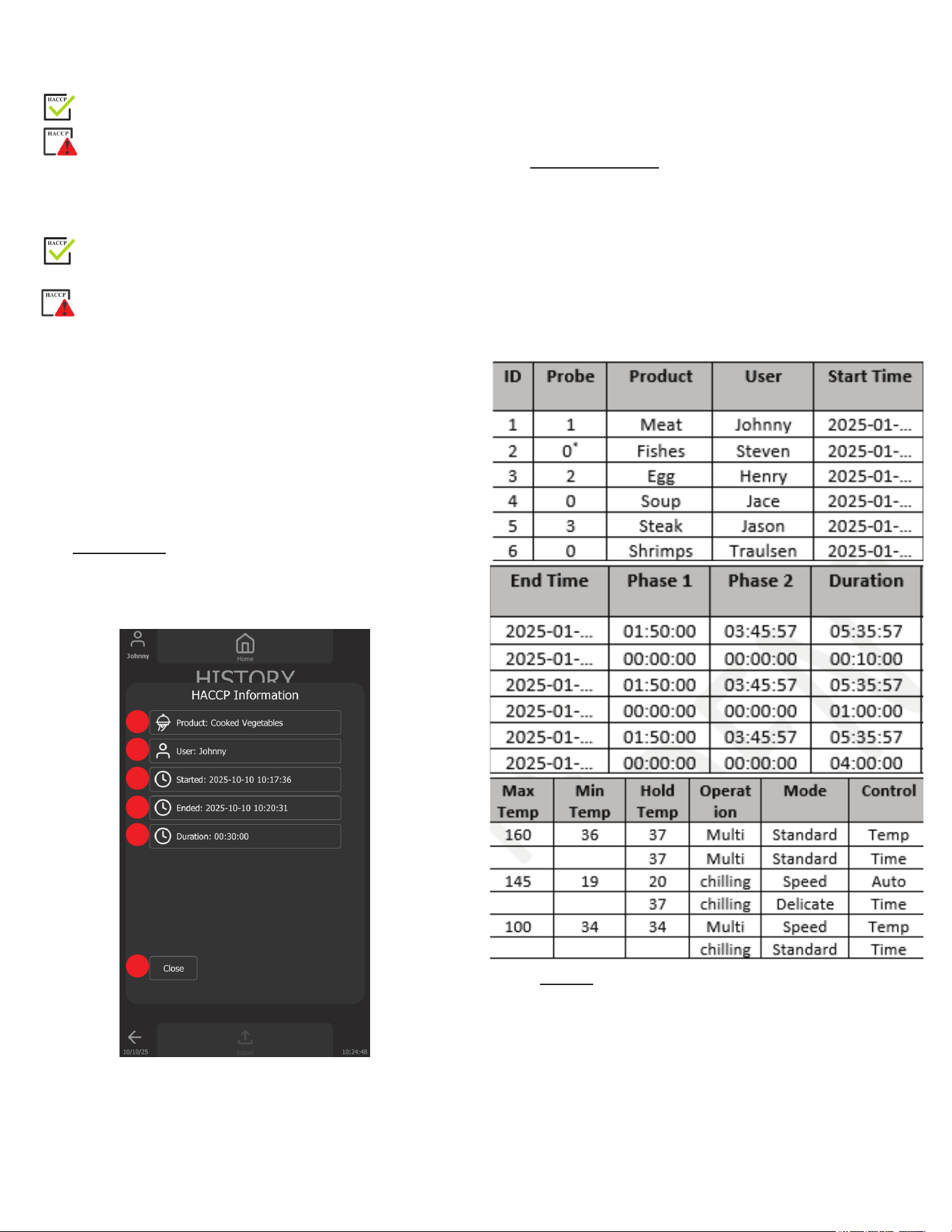
IX. i - HACCP:
Traulsen's blast chiller is equipped with an advance history feature
that records critical HACCP data during each blast chill cycle,
automatically storing it in a secure database for easy access
at any time. Users can conveniently reprint records or export
the data via USB for external storage or compliance reporting.
Additionally, the system allows users to enable or disable recording
and customize the history retention period, providing exibility
and control over data management.
To view the complete cycle history, users can navigate to the
History page by pressing the History button on the Home page.
The following screen will be displayed.
1. Home Button: Tap to return to the Home page.
2. Filtering Buttons: Tap to lter the HACCP records
3. Date column: Displays the start date of each recorded cycle
4. Time column: Displays the start time of each recorded cycle
5. Control column: Indicates whether the cycle was temperature
or time-based
6. Mode column: Displays the selected chill mode (Standard,
Speed, or Delicate)
7. Operation column: Displays the type of operation (Chill,
Freeze, or Multi-Operation)
8. Duration column: Displays the total duration of the operation
9. Return Button: Tap to return to the Home Page
10. Export Button: Tap to export the data displayed in the list if
USB device is plugged in
IX. j - TEMPERATURE CYCLE:
The HACCP record is displayed upon completion of a chill cycle
(see gures below) or can be reviewed on the History page.
After the cycle ends, users can modify the product name and
user name. However, once the record is veried and saved, no
further changes can be made.
1. Product Name: Displays the name of the chilled product
2. Edit Button: Tap to open the product name gallery for selection
3. Active User: Displays the name of the logged-in user
4. Edit Button: Tap to open the username gallery for selection
5. Chill Start Time: Date and time when the product chilling
process began (YYYY-MM-DD HH:MM:SS).
6. Chill End Time: Date and time when the product reached the
set target temperature (YYYY-MM-DD HH:MM:SS).
7. Cooling Duration (135°F to 70°F): Time taken to cool the
product from 135°F to 70°F (HH:MM:SS).
1
2
3 4 5 6 7 8
9 10
1 2
3 4
5
6
7 8
9
10
11
12
13
14
15
-16-
IX. Operation (continued)
-17-
8. Cooling Compliance Indicator (135°F to 70°F):
• Indicates the product cooled to 70°F within 2 hours.
• Indicates the product did not meet the required cooling
time.
9. Cooling Duration (70°F to 41°F): Time taken to cool the
product from 70°F to 41°F (HH:MM:SS).
10. Cooling Compliance Indicator (135°F to 70°F):
• Indicates the product cooled to 41°F within an additional
4 hours.
• Indicates the product did not meet the required cooling
time.
11. Highest Recorded Temperature: Displays the maximum
temperature recorded during the cycle.
12. Lowest Recorded Temperature: Displays the minimum
temperature recorded during the cycle.
13. Total Chill Time: The total duration required to complete the
chilling process.
14. Holding Temperature: The set temperature to maintain after
the chill cycle is complete.
15. Close Button: Tap to close the HACCP dialog.
IX. k - TIME CYCLE:
For time cycle, the HACCP record requires fewer parameters.
However, the controller continues to record essential data. Refer
to the gure below for more details.
1. Product Name: Displays the name of the chilled product.
2. Active User: Displays the name of the logged-in user.
3. Chill Start Time: Date and time when the product chilling
process began (YYYY-MM-DD HH:MM:SS).
4. Chill End Time: Date and time when the product reached the
set target temperature (YYYY-MM-DD HH:MM:SS).
5. Total Chill Time: The total duration required to complete the
chilling process.
6. Close Button: Tap to close the HACCP dialog.
IX. l - EXPORTED DATA:
The HACCP data can be exported into the USB device with the
characteristics:
• Maximum capacity = 32 GB
• Formatted in FAT32 (default allocation unit size = 4096 bytes)
or formatted in FAT (default allocation unit size = 32 Kilobytes)
The table below shows an example of exported HACCP data.
NOTE: 0 means core probe is not in used. Timer-based cycle
was selected.
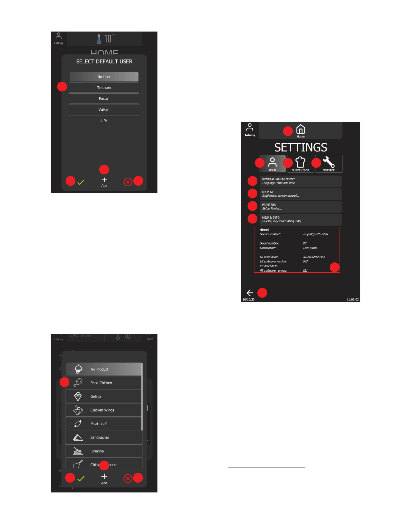
IX. m - USERS:
The Users feature in the blast chiller allows for assigning and
managing the active operator. This functionality helps streamline
kitchen operations by clearly identifying the user responsible.
By setting up an active operator, kitchen sta can track usage,
maintain accountability, and ensure ecient workow management
within the kitchen environment.
Usernames can be easily added by selecting the desired name
directly from the list. To remove a username, go to the Settings
section.
1
2
3
4
5
6
IX. Operation (continued)
1. User List: Tap to select an active user.
2. Add Button: Tap to open the virtual keyboard to enter the new
username.
3. Accept Button: Tap to accept the change and close.
4. Cancel Button: Tap to cancel and close.
IX. n - PRODUCTS:
The Products feature in the blast chiller allows user s to select a
default product name, making it ideal for those who consistently
chill the same product. This feature streamline operations by
saving time and ensuring accuracy in product identication during
repeated use.
Product names can be modied during or after a blast chill cycle,
and additional product names can be added by selecting from
the list. To remove a product name, go to the Settings section.
1. Product List: Tap to select an active product.
2. Add Button: Tap to open the virtual keyboard to enter the new
product name.
3. Accept Button: Tap to accept the change and close.
4. Cancel Button: Tap to cancel and close.
IX. o - SETTINGS:
The Settings Page is divided into three main sections: User
Settings, Supervisor Settings, and Service Settings.
Each section is designed for streamlined conguration and
management.
1. Home Button: Tap to return to Home Page
2. User Button: Tap to see all User Settings
3. Supervisor Button: Tap to access the Supervisor Settings
(Password is 1234)
4. Service Button: Tap to access the Service Settings
(Password is 4401)
5. General Management Button: Tap to modify general settings
(see User Settings section)
6. Display Button: Tap to modify the Display Settings
(see User Settings section)
7. Printer Button: The device supports both receipt & label printers
via Bluetooth Classic. Compatible manufacturers & models
are: Epson TM-m30 ; Star Micronics mC-Print3 ; or
Star Micronics mC-Label3
8. Help & Information Button: Tap to open user manual
9. Return Button: Tap to return to the Home Page
10. About Info: Unit information
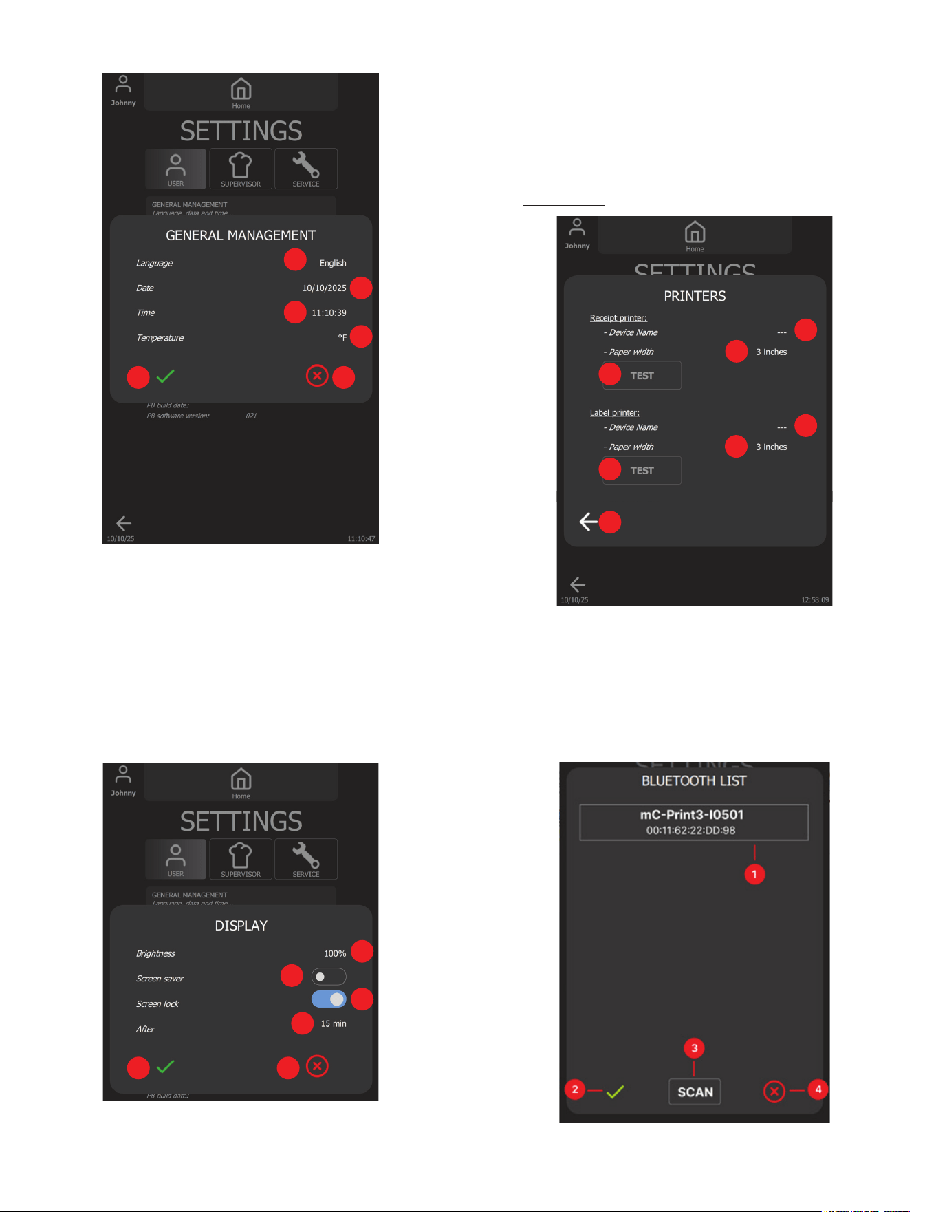
IX. p - GENRAL MANAGEMENT:
Continued on next page.
1
2
3 4
1
2
3
4
10
1
2 3 4
5
6
7
8
9
-18-
IX. Operation (continued)
-19-
3. Screen Lock Switch: Tap to turn it on or o
4. Active Time: Tap to change the active time to activate the
screen saver and screen lock
5. Accept Button: Tap to accept all changes and close
6. Cancel Button: Tap to discard all changes and close
IX. r - PRINTERS:
1. Device Name: Connected receipt printer name
2. Paper Width: Tap to select the receipt paper size
3. Test Button: Tap to print a test receipt
4. Device Name: Connected label printer name
5. Paper Width: Tap to select the label paper size
6. Test Button: Tap to print a test label
7. Return Button: Tap to close the dialog
1. Bluetooth device list
1. Language List: Tap to change current language (English,
Spanish, French).
2. Date: Tap to change the current date (MM:DD:YYYY).
3. Time: Tap to change the current time (HH:MM:SS)
4. Temperature Unit: Tap to change the current measurement
unit (Fahrenheit, Celsius)
5. Accept Button: Tap to accept all changes and close
6. Cancel Button: Tap to discard all changes and close
IX. q - DISPLAY:
1. Brightness Control: Tap to change the display brightness
2. Screen Saver Switch: Tap to turn it on or o
1
2
3
4
5 6
1
2
3
4
5 6
1
2
3
4
5
6
7
IX. Operation (continued)
2. Accept Button: Tap to accept the changes and close.
3. Scan Button: Tap to re-scan devices.
4. Cancel Button: Tap to discard all changes and close.
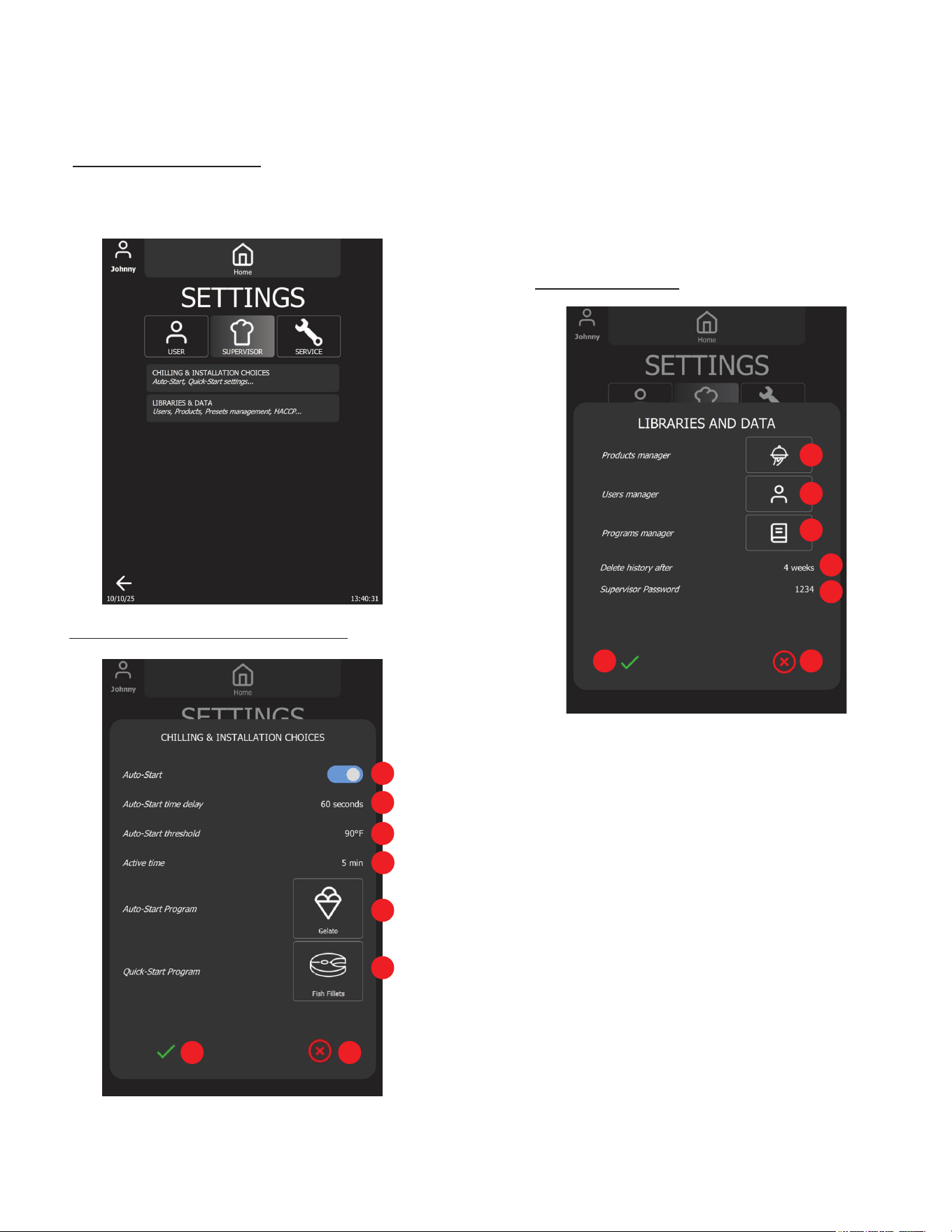
IX. s - SUPERVISOR SETTINGS:
Supervisor settings are secured and can only be modied by
authorized kitchen personnel. To access the Supervisor settings,
enter the default access code (1234).
IX. t - CHILLING & INSTALLATION CHOICES:
1. Auto-Start Switch: Enable or disable the feature.
2. Auto-Start Time Delay: Tap to turn on the virtual keypad to
change the countdown timer until the blast chill cycle started
automatically.
3. Auto-Start Threshold: Tap to turn on the virtual keypad to
change the temperature threshold to trigger auto-start count
down.
4. Active Time: Tap to turn on the virtual keypad to change the
time to switch back to Home page and to trigger auto-start.
5. Auto-Start Program: Tap to change the Auto-Start program.
6. Quick-Start Program: Tap to change the Quick-Start program.
7. Accept Button: Tap to save all changes and close.
8. Cancel Button: Tap to discard all changes and close.
IX. u - LIBRARIES & DATA:
1. Product Manager Button: Tap to add or delete the Product
names
2. User Manager Button: Tap to add or delete the usernames
3. Program Manager Button: Tap to manage the programs
4. HACCP Record Retention Period: Tap to adjust the record
retention duration
5. Supervisor Password: Tap to change the password
6. Accept Button: Tap to accept all changes and close
7. Cancel Button: Tap to discard all changes and close
1
2
3
4
5
6
7 8
-20-
1
2
3
4
5
6 7
IX. Operation (continued)
X. a) SERVICE INFORMATION
Before calling for service, please check the following:
Is the electrical cord plugged in? NOTE: If the SUPPLY CORD is damaged, it must be replaced by the manufacturer, its
service agent, or similarly qualied persons in order to avoid a possible electrical hazard.
Is the fuse OK or circuit breaker on?
Is the condenser coil clean?
Is the power switch on?
If after checking the above items and the unit is still not operating properly, please contact an authorized Traulsen service agent:
4401 Blue Mound Road Fort Worth, TX 76106 | (800) 825-8220. Traulsen reserves the right to change specications or
discontinue models without notice.
NOTE: The ISO 7010-W021 symbol is a standardized safety sign used internationally to indicate a potential re hazard. It features
a black ame icon on a triangular yellow background with a black border, following ISO guidelines for warning symbols. This
appliance is marked with the ISO 7010-W021 warning label to indicate the presence of FLAMMABLE REFRIGERANTS. Prior
to beginning work on systems containing FLAMMABLE REFRIGERANTS, safety checks are necessary to ensure that the risk of
ignition is minimized.
VENTILATED AREA
Ensure that the area is in the open or that it is adequately ventilated before breaking into the system or conducting any hot work.
A degree of ventilation shall continue during the period that the work is carried out. The ventilation should safely disperse any
released refrigerant and preferably expel it externally into the atmosphere.
CABLING
Check that cabling will not be subject to wear, corrosion, excessive pressure, vibration, sharp edges, or any other adverse
environmental eects. The check shall also take into account the eects of aging or continual vibration from sources such as
compressors or fans.
DETECTION OF FLAMMABLE REFRIGERANTS
Under no circumstances shall potential sources of ignition be used in the searching for or detection of refrigerant leaks. A halide
torch (or any other detector using a naked ame) shall not be used.
The following leak detection methods are deemed acceptable for all refrigerant systems. Electronic leak detectors may
be used to detect refrigerant leaks but, in the case of FLAMMABLE REFRIGERANTS, the sensitivity might not be adequate, or
might need recalibration. (Detection equipment shall be calibrated in a refrigerant-free area.) Ensure that the detector is not a
potential source of ignition and is suitable for the refrigerant used. Leak detection equipment shall be set at a percentage of the
LFL of the refrigerant and shall be calibrated to the refrigerant employed, and the appropriate percentage of gas (25 % maximum)
is conrmed.
Leak detection uids are also suitable for use with most refrigerants but the use of detergents containing chlorine shall be avoided
as the chlorine can react with the refrigerant and corrode the copper pipe-work.
NOTE: Examples of leak detection uids are
• bubble method
• uorescent method agents
If a leak is suspected, all naked ames shall be removed/extinguished.
X. Service & Warranty Information
-21-
-22-
X. Service & Warranty Information (continued)
If a leakage of refrigerant is found which requires brazing, all of the refrigerant shall be recovered from the system, or isolated (by
means of shut o valves) in a part of the system remote from the leak. Removal of refrigerant shall be according to the removal &
evacuation section below.
REMOVAL & EVACUATION
When breaking into the refrigerant circuit to make repairs- or for any other purpose - conventional procedures shall
be used. However, for ammable refrigerants it is important that best practice be followed, since ammability is a consideration.
The following procedure shall be adhered to:
a) safely remove refrigerant following local and national regulations;
b) purge the circuit with inert gas;
c) evacuate
d) purge with inert gas;
e) open the circuit by cutting or brazing.
The refrigerant charge shall be recovered into the correct recovery cylinders if venting is not allowed by local and national codes.
For appliances containing ammable refrigerants, the system shall be purged with oxygen- free nitrogen to render the appliance
safe for ammable refrigerants. This process might need to be repeated
several times. Compressed air or oxygen shall not be used for purging refrigerant systems .
For appliances containing ammable refrigerants, refrigerants purging shall be achieved by breaking the vacuum in the system
with oxygen-free nitrogen and continuing to ll until the working pressure is achieved, then venting to atmosphere, and nally
pulling down to a vacuum. This process shall be repeated until no refrigerant is within the system (optional for A2L). When the nal
oxygen-free nitrogen charge is used, the system shall be vented down to atmospheric pressure to enable work to take place.
Ensure that the outlet for the vacuum pump is not close to any potential ignition sources and that ventilation is available.
IX. b) SPARE PARTS INFORMATION
To purchase replacement parts or to speak to service support for Traulsen units please contact our Ft. Worth facility by phone at
800-825-8220 or fax to 817-740-6748 (parts) or 817-740-6757 (service).
Note: When calling for spare parts or service support, please make sure you have model and serial number of unit available.
4401 Blue Mound Rd.
Ft. Worth, TX 76106
800-825-8220
Input Power (ELIN) - FOR INDOOR USE ONLY
115-208/230V ~ 60Hz 8.0A (8,0A)
MODEL:
MODELO:
MODELE:
RDT232WUT-FHS
S/N: T25364A14
REFRIGERANT / REFRIGERANTE / RÉFRIGÉRANT
SYS1 (REFM): R-134a 8.4oz 238.1 g (238,1 g)
Hi Press. (PRESH): 500psi 3.45 MPa (3,45 Mpa)
Lo Press. (PRESL): 250 psi 1.72 Mpa (1,72 Mpa)
SYS2 (REFA): R-404a 12.5oz 354.4g (354,4g)
Hi Press. (PRESH): 500psi 3.45MPa (3,45MPa)
Lo Press. (PRESL): 250psi 1.72Mpa (1,72Mpa)
(Symbol 1)
(Alt Safety / Other
1)
(Symbol 2)
(Alt. San / Other 2)
(Symbol 3)
(Alt. En. / Other 3)
(Symbol 4)
(WEEE)
(Symbol 5)
(Safety)
(Symbol 6)
(Sanitaon)
(Symbol 7)
(Energy)
(Symbol 8)
(Customer QR
Code / Other 4)
Device/Part Number: PartNum (UL/NSF Notes)
SCAN FOR SERVICE INFO
COMPONENTS / COMPOSANTS / COMPONENTES
COMP AMPS: EVAP FAN AMPS:
COND FAN AMPS: LIGHT WATTS:
DEF HTR AMPS: CTRL AMPS:
DOOR HTR AMPS: MIN AMPS:
MAX AMPS:
370-60297-00 REV.A 11/20/14
IX. c) WARRANTY REGISTRATION
The warranties for your new Traulsen unit may be registered with us by completing warranty information online, via our website
www.Traulsen.com. Click on the Warranty Registration text of the Service tab at the top of the home page. You may also register
your product by calling us directly at 800-825-8220.
Model Number
Serial Number
XI. Troubleshooting
POTENTIAL CAUSE SOLUTION
a. No power to unit. Check power supply and circuit breaker.
b. System problem. Call for service.
a. Door not closed properly. Close door completely.
b. Too much product loaded. Adjust the load to not exceed capacity of the unit.
c. Product depth in pan exceeds 2”. Reduce pan load.
d. Pan has been covered with a lid, plastic wrap Cover product correctly.
or foil, and this is not in direct contact with the product.
SYMPTOM
1. No display on control.
2. Batch requires too much time to chill
product down target temperature or
time.
-23-
POTENTIAL CAUSE SOLUTION
e. Product loaded is of a high density. Allow additional chilling time.
f. Dirty condenser coil. Clean condenser coil.
g. Evaporator coil iced. Allow chiller to defrost.
a. Probe not available. Press DONE to release probe for use.
b. Probe not placed in product. Place probe in product.
c. Food probe placed in product below 90° F. Manually program cycle and select probe.
d. Damaged or defective food probe. Replace with new food probe.
a. Door open. Close door.
b. Hot product inside but no probe placed. Press CANCEL then place probe to start cycle.
a. Previously chilled product not removed. Remove DONE product before starting a new chill cycle.
b. Chill cycle By Time set for too long. Reduce cycle time.
c. High water content food (ex. soup). Use DELICATE method.
a. Food chilled uncovered. Cover food before placing in chiller.
a. Door out of alignment or gasket issue. Check door alignment and gasket for proper seal.
b. Door sweep worn/out of adjustment (TBC1H). Adjust/replace door sweep.
c. Electric door heater malfunction. Call for service.
a. Varied product temps within batch. Verify actual product temp using a manual thermometer.
b. Probe placed incorrectly. Relocate probe.
c. Small mass product (ex. chicken tender). Use chill by time.
d. Product held at room temp too long. Verify actual product temp using a manual thermometer.
BACK COVER
RECEPTACLE
LOCATION
DRAIN TUBE
CONDENSATE
EVAPORATOR
ASSEMBLY
BMCE
BRACKET
1/4-20 X 1/2 HWH
MACHINE SCREW
1. INSTALL THE UNIT ON THE SUPPORTS (CASTERS/LEGS).
2. LOCATE THE MOUNTING HOLES ON THE SYSTEM BASE
UNDERSIDE OF THE UNIT (BEHIND THE CASTER/LEG CHANNEL).
3. MOUNT THE BMCE BRACKET WITH PROVIDED SCREWS (1/4"-20 X 1/2" HEX
HEAD).
4. PLACE THE CONDENSATE EVAPORATOR ASSEMBLY ONTO THE BMCE BRACKET
WITH THE PLUG FACING THE RECEPTACLE LOCATION (SEE DRAWING).
5. INSERT THE PLUG INTO THE RECEPTACLE MAKING SURE IT IS FULLY INSERTED.
6. PLACE THE LOOSE END OF THE PLASTIC DRAIN TUBE INTO THE CONDENSATE
EVAPORATOR ASSEMBLY.
7. IF CONDENSATE EVAPORATOR ASSY. CORD INTERFERES WITH CASTER
MOVEMENT, SECURE IT TO THE BACK COVER USING WIRE TIES.
8. VERIFY THAT THE HEATER IS WORKING. IF IT IS NOT WORKING THE PLUG IS NOT
FULLY INSERTED INTO THE RECEPTACLE OR IT NEEDS TO BE REINSERTED
THE OTHER DIRECTION.
NO SCALE
SIZE
DWG. NO.
A
REV.
MATERIAL
FINISH
SEE VIEW
--
DO NOT SCALE DRAWING
DIMENSIONS ARE IN INCHES
TOLERANCES:
NAME
DATE
DRAWN
CHECKED
ENG APPR.
MFG APPR.
Q.A.
SHEET 1 OF 1
WEIGHT: 0
COMMENTS:
THIS DOCUMENT CONTAINS PROPRIETARY AND CONFIDENTIAL DATA OF TRAULSEN & CO. INC.
NO DISCLOSURE, REPRODUCTION OR USE OF ANY PART THEREOF MAY BE MADE WITHOUT
WRITTEN PERMISSION OF TRAULSEN & CO. INC.
ANY VENDOR SUPPLYING PARTS UNDER THIS DRAWING AGREES NOT TO REVISE ANY PHYSICAL,
DIMENSIONAL, MATERIAL OR PERFORMANCE CHARACTERISTICS OF SUCH PARTS AFTER
APPROVAL BY TRAULSEN & CO. INC. GROUP OF VENDOR SAMPLES UNLESS AUTHORIZED IN
WRITING BY TRAULSEN & CO. INC.
PROPRIETARY AND CONFIDENTIAL
000-98334-00
B
.XX
.03 FRACTIONS
1/32
.XXX
.015 ANGLES
1/2
HOLES
.005
PARTS ARE TO FREE OF BURRS AND SHARP EDGES
INSTALLATION INSTRUCTIONS
CAH
8/7/13
000-98334-00
BMCE TBC13
PLASTIC
SHIPPING
NUT
SYMPTOM
2. Batch requires too much time to chill
product down target temperature or
time (cont'd).
3. Auto mode does not appear to work
when placing probe in hot product.
4. Chill cycle starts with no product
present.
5. Unwanted product freezing.
6. Food drying out during chilling.
7. Condensation on exterior surface.
8. Upon starting a chill cycle, the
product temperature displayed
appears cooler than expected (cooked)
temperature.
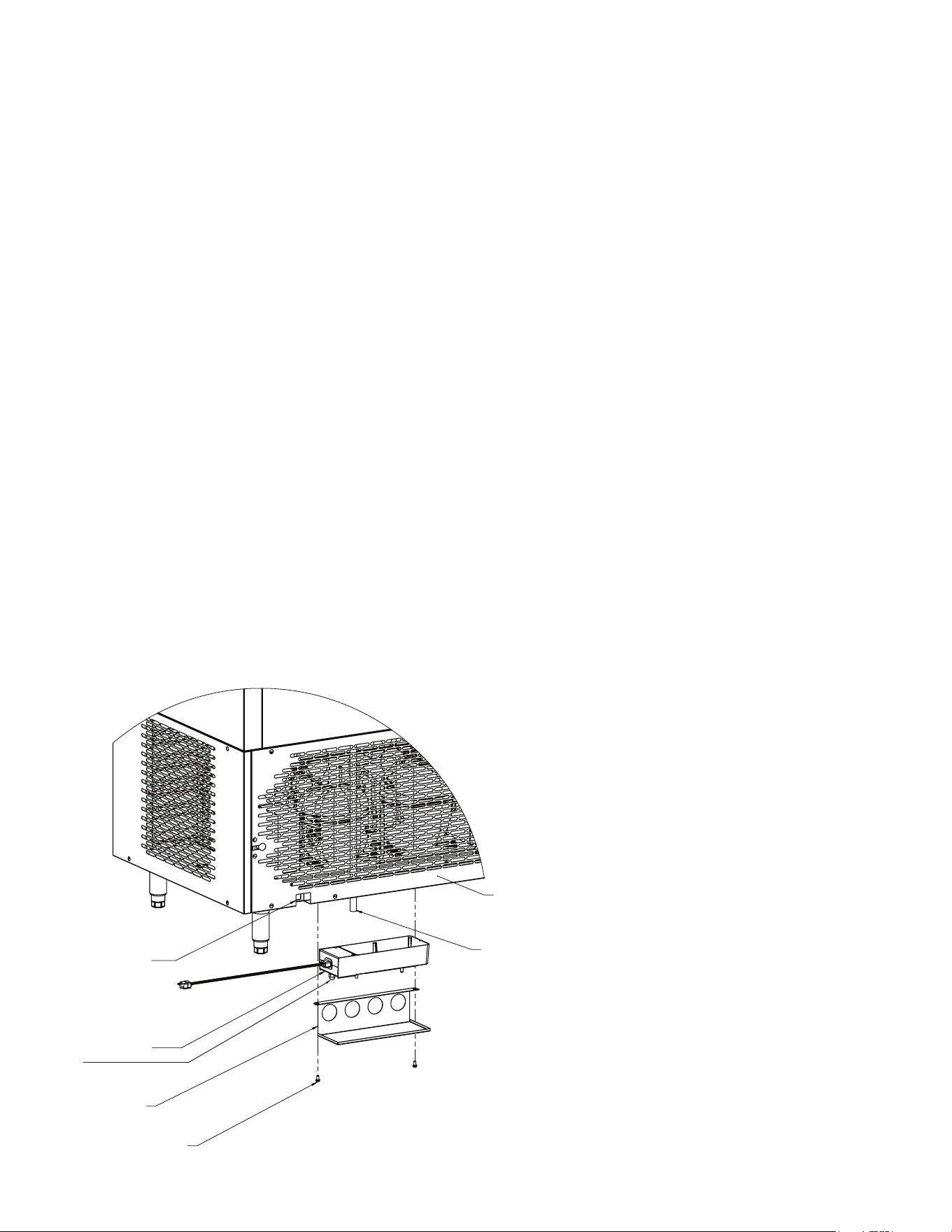
XII. TBC13 Condensate Kit Install Instructions
1. Install the unit on its supports (casters/legs).
2. Locate the mounting holes on the system base
under the unit (behind the caster/leg channel).
3. Mount the BMCE bracket with provided screws
(1/4”-20 X 1/2” hex head).
4. Place the condensate evaporator assembly
onto the BMCE bracket with the plug facing the
receptacle location (see drawing).
5. Insert the plug into the receptacle, ensuring it is
fully inserted.
6. Place the loose end of the plastic drain tube into
the condensate evaporator assembly.
7. If condensate evaporator assembly cord interferes
with caster movement, secure it to the back cover
using wire ties.
8. Verify that the heater is working. If it is not, the
plug is not fully inserted into the receptacle or it
needs to be reinserted the other direction.
9. Remove black plastic shipping nut
from the
bottom of condensate pan.
XI. Troubleshooting (continued)

4401 Blue Mound Road Fort Worth, Texas 76106 (USA)
Phone: 800.825.8220 | Service Fax: 817.740.6757 | E-mail: [email protected] | Website: traulsen.com
Form Number: TR35938 | Part Number: 375-60311-00 | Revision Date: 03/26
Traulsen © All Rights Reserved