Hours of Operation: Monday - Friday 7:30 a.m. - 4:30 p.m.
(CST)
4401 Blue Mound Road Fort Worth, Texas 76106 (USA)
Phone: 800.825.8220 | Service Fax: 817.740.6757 | E-mail: service@traulsen.com | Website: traulsen.com
OWNER’S MANUAL
*Please Note: This manual is intended for use with the above referenced equipment manufactured after February 1, 2026.
Instructions for Installation, Operation, &
Maintenance of C Series Compacts:
Undercounter Refrigerators & Freezers*
Prep Tables and Mega Tops*
-1-
I. THE SERIAL TAG Page 1
a) Serial Tag & Location Page 1
b) Reading The Serial Tag Page 1
II. RECEIPT INSPECTION Page 2
III. INSTALLATION Page 2
a) Location Page 2
b) Packaging Page 2
c) Installing Legs or Casters Page 2
d) Installing Drain Pan Page 3
e) Shelf Clips for Door Models Page 3
f) Cord & Plug Page 3
g) Power Supply Page 3
h) Clearance Page 3
i) Cutting Board Assembly Page 4
j) Installing Backsplash Page 4
IV. OPERATION Page 4
a)Operation Display Indicators Page 4
b) Refrigerators Page 5
c) Freezers Page 5
d) Prep Table & Mega Top Refrigerator Page 5
e) Refrigerating Product Page 5
f) Divider Bars Page 5
V. CARE AND MAINTENANCE Page 6
a) Cleaning the Exterior Page 6
b) Cleaning the Interior Page 6
c) Cleaning the Condenser Coil Page 6
d) Condensate Removal System Care Page 6
e) Door Re-Hinging Page 7
f) Adjusting the Door Page 7
g) Replacing the Gaskets Page 7
h) Preparing for Extended Shutdown Page 8
VI. CONTROL BASICS Page 8
a) Information Menu Page 8
b) Adjusting Cabinet Setpoint Page 8
c) Initiating a Defrost Page 8
d) Configuration Parameters Page 9
e) Technical Data Page 9
f) Components and Wiring Diagram Page 14
VII. TROUBLESHOOTING GUIDE Page 15
VIII. SERVICE/WARRANTY INFORMATION Page 16
a) Service Information Page 16
b) Spare Parts Information Page 17
c) Warranty Registration Page 17
IX. NOTES Page 18
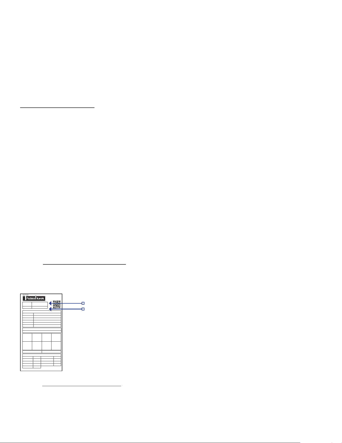
I. THE SERIAL TAG
I. a - SERIAL TAG & LOCATION
The serial tag is a permanently axed label on which is recorded
vital electrical and refrigeration data about your Traulsen
product, as well as the model and serial number. This tag is
located in upper right interior compartment on all compact
models.
I. b - READING THE SERIAL TAG
• Model = The model # of your Traulsen unit
• (S/N) Serial Number = The permanent ID# of your Traulsen unit
• Refrigerant SYS1 = System 1 Refrigerant type used and
refrigerant charge
• Design Pressure = System 1 High and Low Pressure
• Refrigerant SYS2 = System 2 Refrigerant type used and
refrigerant charge
• Design Pressure = System 2 High and Low Pressure
• Volts = Voltage
• Hz = Cycle
• PH = Phase
• Total Current = Maximum amp draw
• Min Circuit Amps = Minimum circuit ampacity
• Lights = Light wattage
• Agency Labels = Designates agency listings
• Components = Component Ratings
TABLE OF CONTENTS
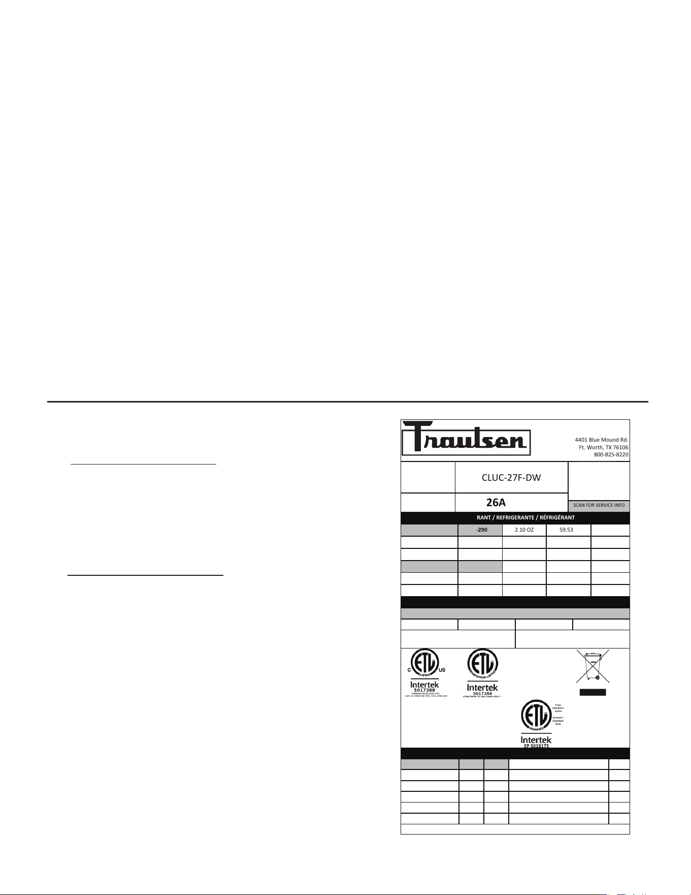
ITW Food Equipment Group, LLC
North American Refrigeration
4401 Blue Mound Rd.
Ft. Worth, TX 76106
800-825-8220
MODEL:
MODELO:
MODELE:
CLUC-27F-DW
SERIAL NUMBER:
26A01799
SCAN FOR SERVICE INFO
REFRIGERANT / REFRIGERANTE / RÉFRIGÉRANT
SYS1 (REFM):
R-290
2.10 OZ
59.53 g
59,53 g
Hi Press. (PRESH):
450.00 psi
3,102.64 kPa
3.102,64 kPa
Lo Press. (PRESL):
200.00 psi
1,378.95 kPa
1.378,95 kPa
SYS2 (REFA):
NA
Hi Press. (PRESH):
Lo Press. (PRESL):
Input Power (ELIN) - FOR INDOOR USE ONLY
Voltage
Hertz
Phase
Total Amps
115 ~
60
1
5.30
Device/Part Number:
CLUC-27F-DW
Device/Part Notes:
COMPONENTS / COMPOSANTS / COMPONENTES
1
2
MAX OVER CURRENT PROTECTION (A):
COMP AMPS:
MIN CIRCUIT IN AMPS:
COND FAN AMPS:
DOME LIGHT WATTS:
EVAP FAN AMPS:
DISPLAY LIGHT WATTS:
CONTROL AMPS:
DOOR HEATER WATTS:
DEF HEATER WATTS:
B/TMCE HTR WATTS:
370-60297-00 REV. D 01/15/2024
-2-
II. RECEIPT INSPECTION III. INSTALLATION (continued)
II. a - RECEIPT INSPECTION
All Traulsen products are factory tested for performance
and are free from defects when shipped. The utmost care
has been taken in crating this product to protect against
damage in transit.
You should carefully inspect your Traulsen unit for damage
upon delivery. If damage is detected, you should save all
the crating materials and make note on the carrier’s Bill
of Lading describing this. A freight claim should be filed
immediately. If damage is subsequently noted during
or immediately after installation, contact the respective
carrier and file a freight claim. Under no condition may
a damaged unit be returned to Traulsen without first
obtaining written permission (return authorization). You
may contact Traulsen customer care at (800) 333-7447 and
select option 2 to request a return.
SYSTEMS USING REFRIGERANT R-290 (PROPANE)
Traulsen has selected propane as the refrigerant for many
of their products.
In addition to its low global warming potential and impact
on the environment, propane is an ideal refrigerant. It is a
flammable refrigerant, however, which is why you will see
a “flammable refrigerant” sticker on applicable products.
Traulsen products using propane as the refrigerant are
UL approved and are safe to use in accordance with
this Owner’s Manual and general industry practices for
commercial cooking environments.
Please check with local codes or regulations for any
restrictions to products using hydrocarbon refrigerants.
III. INSTALLATION
III. a - LOCATION
Select a proper location for your Traulsen unit, away from
extreme heat or cold. Allow enough clearance between
the unit and the side wall in order to make use of the door
stay open feature at 120° (self-closing feature operates
up to 90°). The door(s) must be able to open a minimum
of 90° in order to make use of the maximum clear door
width available.
NOTE: Do not install the cabinet without casters.
III. b - PACKAGING
All Traulsen units are shipped on casters from the factory,
secured to a sturdy wooden pallet using tie-wraps and
packaged in a durable cardboard container.
The cabinet should remain secured to the pallet during
transportation, to the point of installation. To remove the
cabinet from the wooden pallet, cut the tie-wraps using
a cutter. Ensure that the cabinet is properly supported
during this process.
NOTE: Traulsen does not recommend laying the unit down
on its front or side or back. However, if you must only
lay unit on the front of side, not the back and please be
certain to allow the unit to remain in an upright position
afterwards for 24 hours before plugging it in so that the
compressor oils and refrigerant may settle.III. c -
III. c - INSTALLING LEGS OR CASTERS
A set of 4” high casters are supplied standard for all
compact undercounter and prep table units. These are
installed as standard on the cabinet from the factory.
Casters with locks are installed in the front for easy access
to the locking mechanism.
Legs & 6” casters are available in lieu of 4” casters as an
optional accessory kit for the same models. The are shipped
inside a separate cardboard box, containing four/six (4/6)
casters/legs.
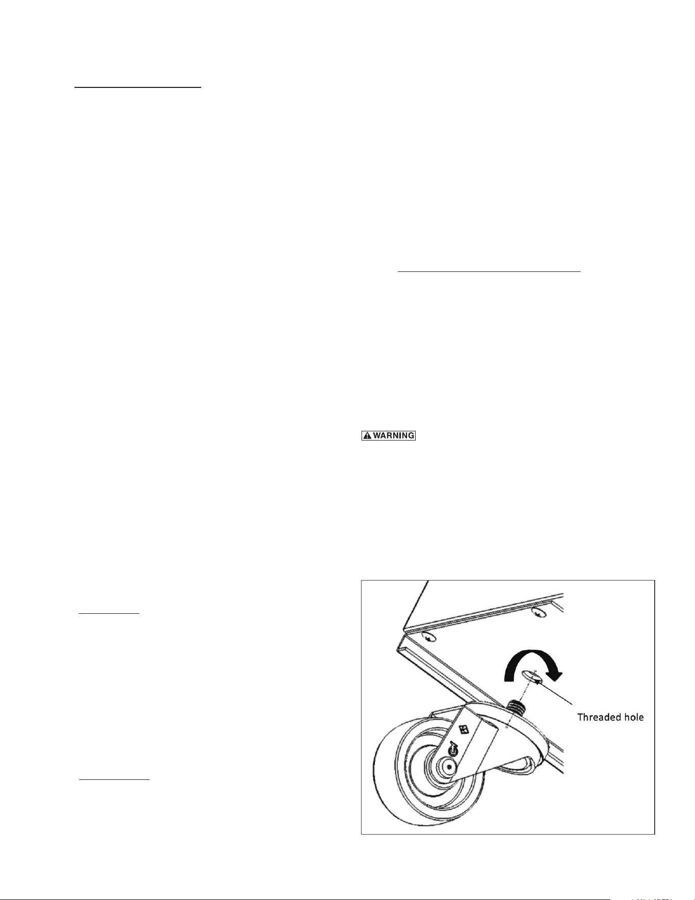
THE CABINET MUST BE BLOCKED AND STABLE
BEFORE INSTALLING CASTERS.
To change the legs or casters, first raise and block the
cabinet a minimum of 7” from the floor. Remove existing
casters by turning them counter-clockwise. For installing
new legs/casters, thread the legs into the threaded holes
on the bottom of the cabinet (see figure 1). Be certain that
all legs are tightly secured.
Fig. 1
-3-
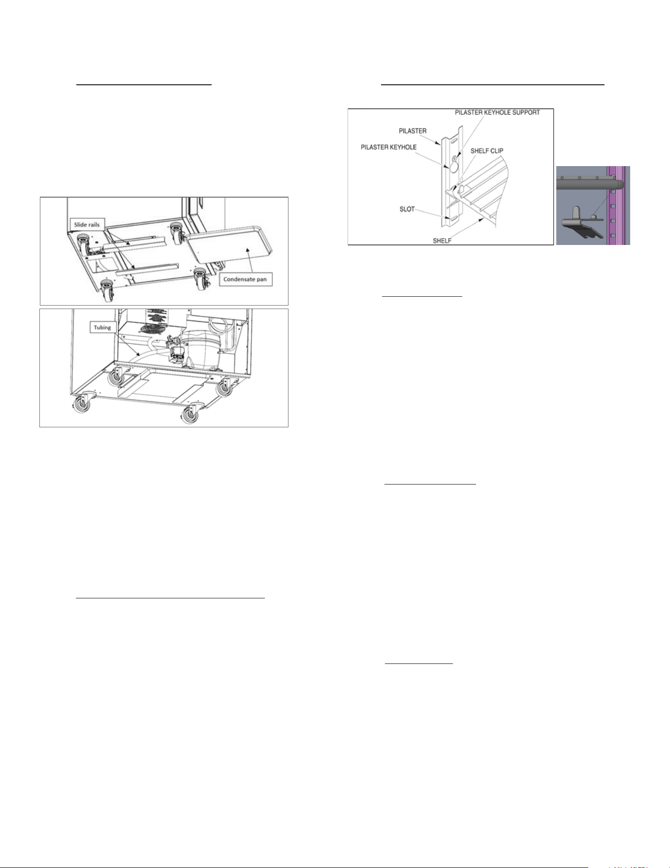
III. d - INSTALLING DRAIN PAN
C Series compact models are shipped with the condensate
pan (half-size sheet pan) wrapped up and stored inside
the unit.
Remove the condensate pan and slide it on the rails
underneath the cabinet. Route the drain tubing drain into
the pan to ensure water drains into the pan (see figure 2).
NOTE: DRAIN PAN IS DESIGNED TO HOLD AND EVAPORATE
DEFROST CONDENSATE FROM THE CABINET DURING
NORMAL OPERATIONS. HOWEVER, DUE TO OTHER
OPERATIONS LIKE FLOOR CLEANING WITH WATER JETS/
SPRAYS, IT MAY GET FULL AND OVERFLOW. IN THOSE CASES,
DRAIN PAN CAN BE SLIDED OUT AND EMPTIED TO PREVENT
SLIP HAZARD.
III. e - SHELF CLIPS FOR DOOR MODELS
Shelves and shelf clips are shipped with the unit. Shelves
are mounted on pilasters using clips to adjust the shelf
height. For each shelf, insert four (4) shelf clips into the
pilaster slots at the same height. The shelf clips have a
small projection on top which holds the shelf in position
and prevents it from slipping forward. To remove the clips,
pinch down on the mounting side and pull them outwards.
Make sure the clips are securely installed. Lastly, set the
shelf into its new position.
III. e - SHELF CLIPS FOR DOOR MODELS (cont’d)
III. f - CORD & PLUG
All C Series compact models are supplied with a cord & plug
attached. It is shipped coiled and secured by a nylon strip
to the back of the cabinet near condensing unit area. For
your safety and protection, all units supplied with a cord
and plug include a special three-prong grounding plug on
the service cord. Select only a dedicated electrical outlet
with grounding plug for power source.
NOTE: DO NOT UNDER ANY CIRCUMSTANCES CUT OR
REMOVE THE ROUND GROUNDING PRONG FROM THE PLUG
OR USE AN EXTENSION CORD.
III. g - POWER SUPPLY
The supply voltage should be checked prior to connection
to be certain that proper voltage for the cabinet wiring
is available (refer to the serial tag to determine correct
unit voltage). Make connections in accordance with local
electrical codes. Use qualified electricians.
Use of a separate, dedicated circuit is required. Size wiring
to handle indicated load and provide necessary over
current protector in circuit (see amperage requirements
on the unit’s serial tag).
III. h - CLEARANCE
In order to assure optimum performance, the condensing
unit of your C Series unit MUST have an adequate supply of
air for cooling purposes. Therefore, the operating location
must have a minimum of 1” clearance on top of the unit
for proper air flow. There are no clearance requirements
for the sides or rear.
Fig. 2
Fig. 3
III. INSTALLATION (continued)
-4-
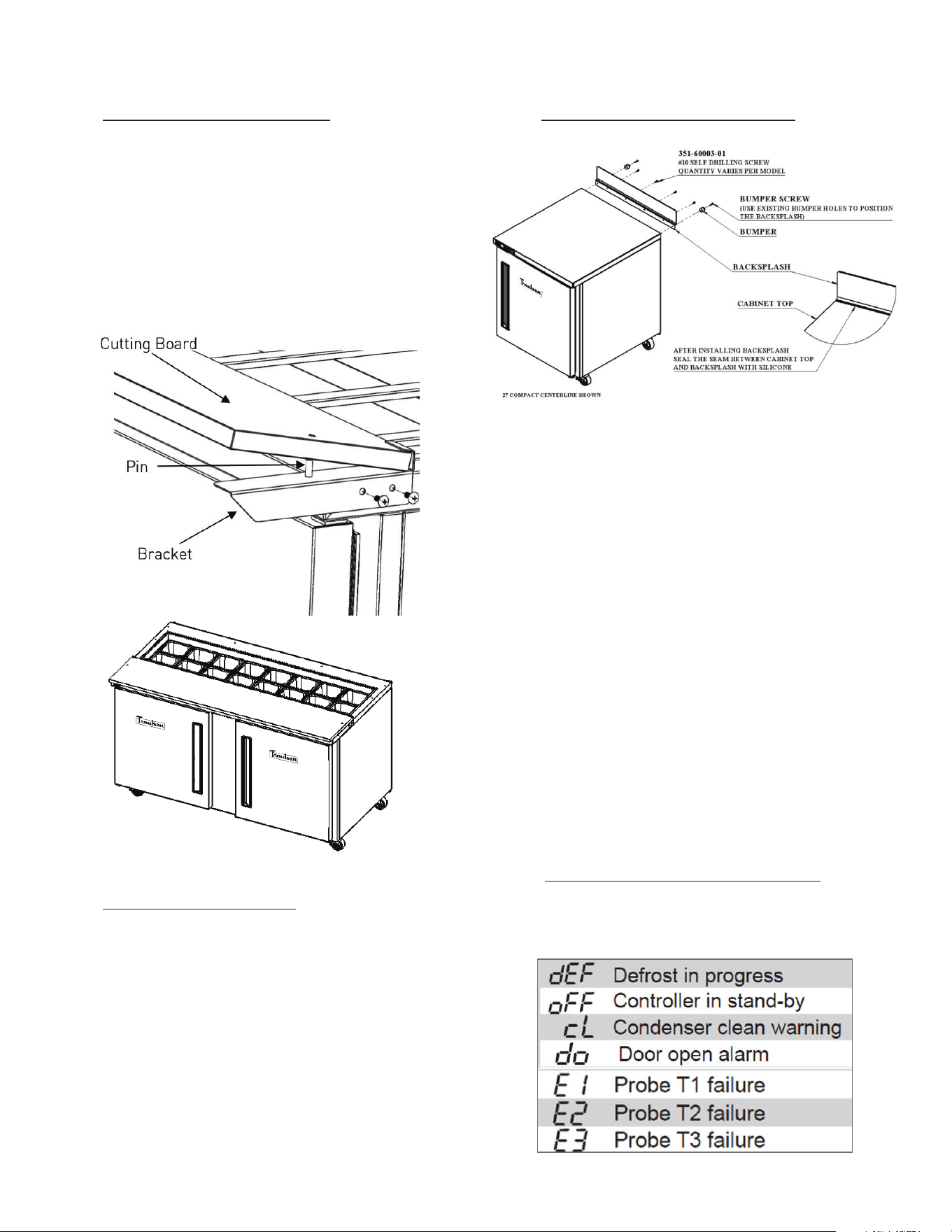
III. i - CUTTING BOARD ASSEMBLY
On prep tables and mega top tables, the cutting board may
require assembly at the site.
Install cutting board brackets on each side with two screws.
With brackets installed, slide the cutting board in at an
angle under the lip in the back and then let it rest down
with the pins running through the holes on the board
(see figure 4). The cutting board is field reversible, reverse
process to reverse cutting board.
III. j - INSTALLING BACKSPLASH
All 27”, 36”, 48”, 60”, & 72” wide compact undercounter
models can be supplied with an optional backsplash that
must be installed on-site. To do so, please follow the
directions below:
III. j - INSTALLING BACKSPLASH (cont’d)
1. Install backsplash as shown in figure 5. The backsplash
is attached with self-drilling Philips head screws. The
outer most holes are used to install bumpers.
2. Align the outer holes used for the bumpers to attach
the backsplash. Attach the backsplash with the just the
outer holes and bumpers temporarily to hold in place.
3. Assure the front lip of the backsplash is contacting
the top of the unit. Use the self-threading sheet metal
screws to attach the inner portion through the hole
locations on the backsplash.
4. Use silicone or similar product to seal any gaps
between the backsplash and the exterior top.
Both refrigerators and freezers do not require manual
defrosting. However, manual defrost option is available
on the control, if required.
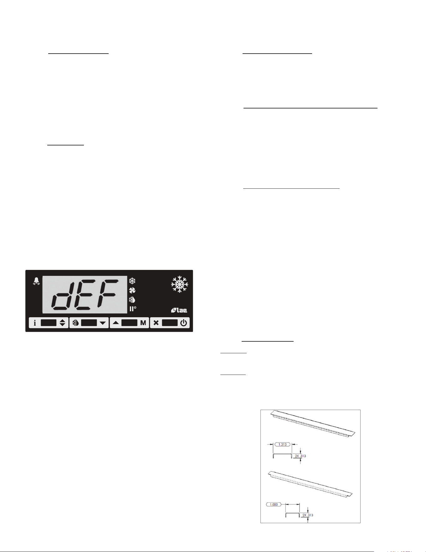
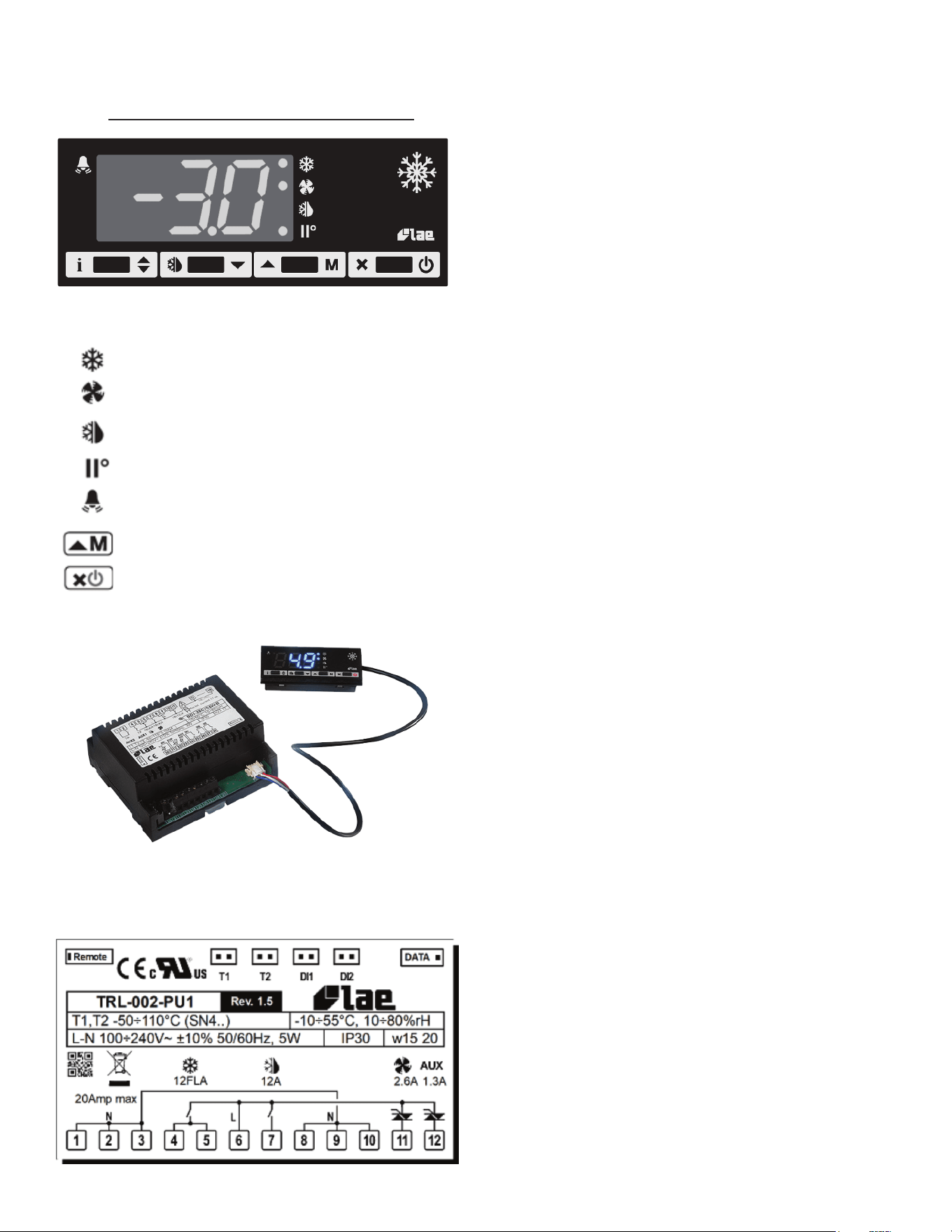
IV. a - OPERATION DISPLAY INDICATORS
During normal operation, the display shows either the
temperature measured or one of the following indications:
III. INSTALLATION (continued)
Fig. 5
Fig. 4
IV. OPERATION
-5-
IV. b - REFRIGERATORS
During normal operation, a refrigerator continuously
circulates above-freezing cabinet air through the evaporator
coil. An Off-Cycle defrost occurs every 8 hours for a
maximum length of 50 minutes to melt any frost which
may accumulate on the coil during the compressor “ON”
cycle. With standard holding refrigerators, high relative
humidity is also maintained to prevent dehydration of
stored product.
IV. c - FREEZERS
During normal operation, a freezer continuously circulates
below-freezing cabinet air through the evaporator coil. The
coil requires a periodic defrosting for proper operation.
This is accomplished by an automatic, compressor runtime
activated, temperature/time terminated, defrost program.
Depending on the door opening frequency and the ambient
condition, the defrost may occur 3 to 8 times within each
24-hour period.
At the start of a freezer defrost cycle, both the compressor
and evaporator fans are o. The microprocessor control
will read “dEF” (see figure 6).
The electric heaters (attached to the evaporator coil and
drip pan) are energized. When the temperature sensor
axed to the coil senses 50°F, the coil and drip pan are
fully defrosted. Both heaters and compressor are o for 5
minutes to let the defrost water drip out completely. After
drip time, compressor will resume operation. The evaporator
coil fans are delayed from starting at the termination of a
defrost cycle. Fan operation is automatically resumed after
a short time or temp delay (whichever comes first). After
completion, the total refrigeration system operation is then
resumed. During defrost operation, heat is confined to the
coil enclosure to prevent any significant rise in temperature
within the food zone. The fan delay control function upon
termination of a defrost cycle is two-fold. First, to prevent
blowing warm air into the food storage area. Second, to
prevent any condensation on the defrost coil from being
blown into the food storage area.
IV. c - FREEZERS (cont’d)
The microprocessor control is set from the factory to
terminate defrost at 25 minutes for freezers in the event
of a sensor failure. This setting should never be tampered
with, without first consulting the factory.
IV. d -
PREP TABLE & MEGA TOP REFRIGERATOR
The prep table and mega top refrigerator will function as
a refrigerator. Due to the open top feature, it runs slightly
lower evaporator temperature and builds more frost on coil
than the regular refrigerator. The prep table and mega top
therefore utilize electric heater for more eective defrost.
The defrost procedure is the same as in freezer described
in section IV.c, except the defrost will be terminated at 45°F
IV. e - REFRIGERATING PRODUCT
C Series compact models will satisfactorily refrigerate an
assorted load of food items. Allow space between articles to
permit free air circulation. Do not overload at any one time
with warm food products and expect immediate results. A
certain amount of time is required to remove heat from
items before operating temperatures can be attained. The
system is designed for storage of refrigerated or frozen
product.
Opening the door or drawer will increase the temperature
in the cabinet and will require a certain amount of time
to recover. Also, after peak service periods or after warm
product is loaded, the refrigerator will require a certain
amount of time for the temperature to return to the normal
operating range.
IV. f - DIVIDER BARS
Top Rail: C Series compacts are provided with standard
width pan divider bars. Pans are not provided with the unit.
Drawers: Drawer models are provided with metal divider
bars standard. All 27” wide models are supplied with
standard width bars. 48” and 72” models are supplied with
2 narrow and 2 wide bars.
Fig. 6
IV. OPERATION (continued)
Fig. 7
-6-
DISCONNECT ELECTRICAL POWER SUPPLY
BEFORE CLEANING ANY PARTS OF THE UNIT.
V. a - CLEANING THE EXTERIOR
Exterior stainless steel should be cleaned with warm water,
mild soap and a soft cloth. Apply with a dampened cloth
and wipe in the direction of the metal grain.
Avoid the use of strong detergents and gritty, abrasive
cleaners as they may tend to mar and scratch the surface.
Do NOT use cleaners containing chlorine, this may promote
corrosion of the stainless steel.
V. b - CLEANING THE INTERIOR
For cleaning the interior, use baking soda with warm water,
and a soft cloth. Apply with a dampened cloth and wipe in
the direction of the metal grain Use on breaker strips as
well as door and drawer gaskets.
All door models interior fittings are removable without tools
to facilitate cleaning. Depending on the level of cleaning,
drawer model interior fittings may require a tool to facilitate
cleaning. The drawer frame may be removed without tools.
To remove the drawers, the lock tab must be unlocked by
sliding the lock tab forward and then up, to loosen the
slides (see figure 8). Then the drawer can be pulled out
easily. from the slides.
To remove the middle slide between the drawer and cabinet
for deeper cleaning, remove the middle slide by lifting up
on the back tab and sliding it out of the track.
Caution: The outer slides attached the side of the cabinet
should not be removed because there are washers set
in the assemble to hold the proper spacing between the
slides. If removed the drawer slides may not function
properly.
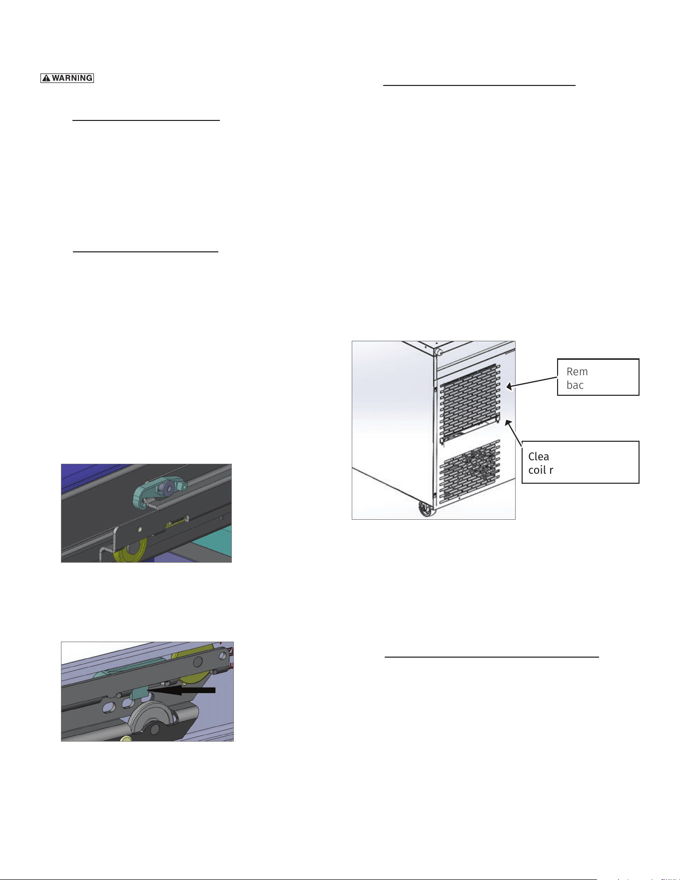
V. c - CLEANING THE CONDENSER COIL
Clean the condenser coil every three months. The
operating environment will aect the required frequency
of cleaning. Air must be able to freely circulate through
the condenser. This surface must be kept free of dirt
and grease for proper system operation. The condenser
coil is at the back of the cabinet and comes with a back
cover installed. This cover should stay on while the unit
is working. For cleaning purposes, take o the back cover
and carefully clean dirt and lint from the condenser coil
using a vacuum cleaner or soft brush; do not use a wire
brush. To remove the cover, remove the thumb screw
and then slide it through the keyholes. After cleaning,
re-install the back following the same steps listed above.
Ensure that the thumb screw is installed to lock the
cover in place.
SYSTEMS USING REFRIGERANT R-290 (PROPANE)
Remove any ignition source (arc, flame, heat) before
cleaning the condenser coil. If the condenser coil is
inadvertently damaged during cleaning to the point of
causing a refrigerant leak, immediately ventilate the area
and call for service.
V. d -
CONDENSATE REMOVAL SYSTEM CARE
Condensate removal is provided by evaporation at the
pan at the bottom of the equipment cabinet and does not
need a drain. Clean the condensate removal pan by wiping
it out with a clean damp cloth. Replace the pan back to its
location
V. CARE AND MAINTENANCE
Fig. 8
Drawer lock tab
shown in unlocked
position.
Fig. 9
Fig.10
Remove the
back cover.
Clean the condenser
coil routinely.
-7-
V. e - DOOR RE-HINGING
The door(s) on all compact models can be easily re-hinged
in the field. Existing hinge cartridge and top hinge bracket
can be reused but an opposite side bottom hinge bracket
will be needed. This bracket can be obtained from the
factory by contacting our parts department (see section
VIII.b) To begin, open the door to its stay-open feature
position. Support the non-hinged end of the door so that
minimum movement occurs when the bolts from the lower
hinge brackets are removed. Remove the lower hinge
bracket and then the door from the top hinge bracket. The
hinge bracket pin and plastic bushing will remain in the
top hinge bracket.
Carefully lay the door down on a padded flat surface. The
door must be rotated 180° to mount on the other side of
cabinet. Remove top bushing and bottom hinge cartridge
and install on opposite ends. Using the newly obtained
bottom hinge bracket, follow the steps in reverse order to
re-hinge the door.
V. e - DOOR RE-HINGING (cont’d)
NOTE: The lower hinge plate is under spring tension. Grasp
the lower hinge plate while keeping a firm grip on the
plate, carefully slide it out the bottom of the door just far
enough to allow the plate to rotate a full 360°. Unwind the
tension of the spring by carefully allowing the hinge plate
to rotate a full 360 degrees several times.
V. f - ADJUSTING THE DOOR
Occasionally the door(s) may require alignment adjustment.
To do so, first open the door and loosen the hinge plate
screws enough to move the hinges if desired, but the door
is held in place. Center the door in the opening. Next level
the top hinge plate and tighten the screws. Finally, level
the lower hinge plate and tighten the screws.
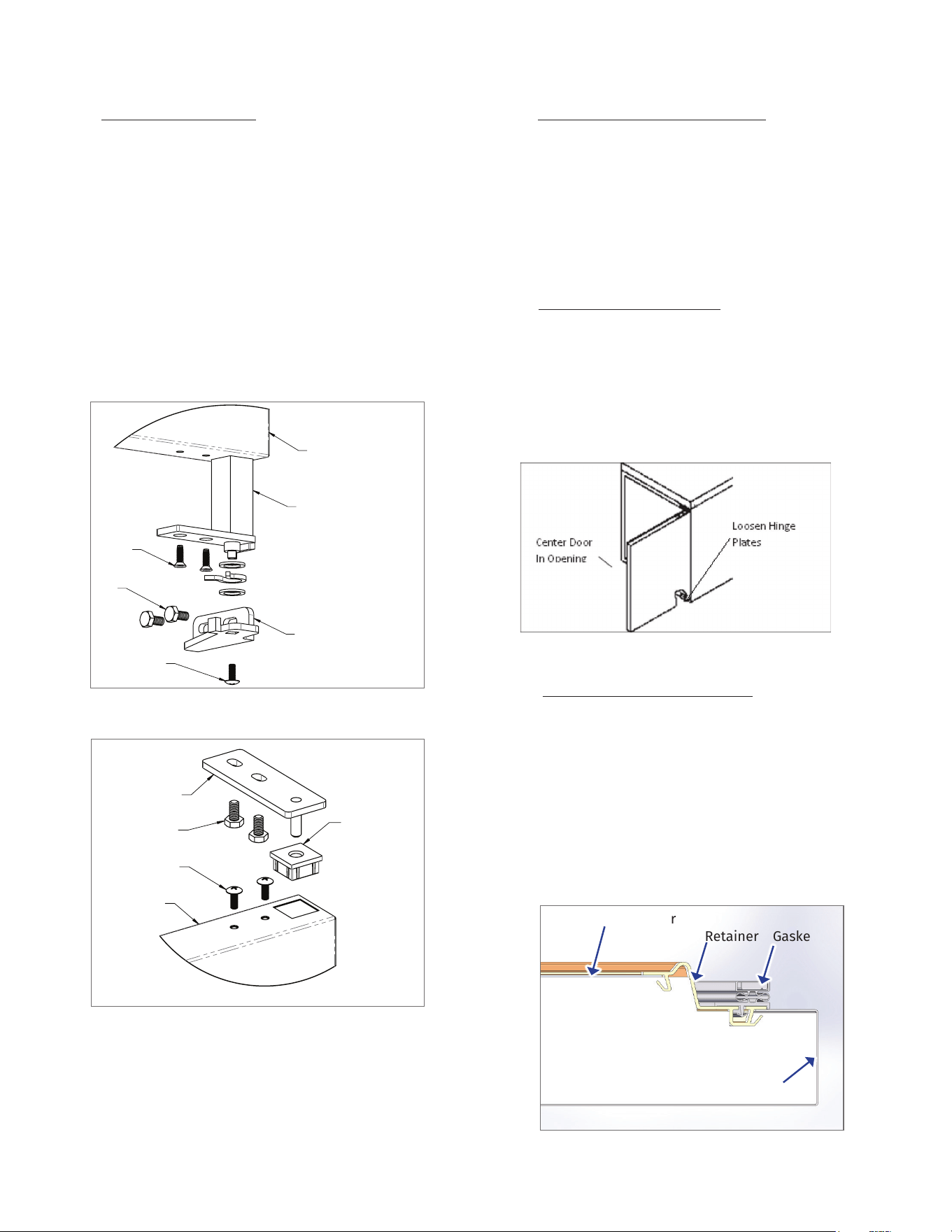
V. g - REPLACING THE GASKETS
To replace the gasket, grasp it firmly by one corner and pull
it out. Before attempting to install a new gasket, both the
unit and gasket must be at room temperature. Insert the
four corners first by using a rubber mallet (or hammer with
a block of wood). After the corners are properly inserted,
work your way towards the center from both ends by gently
hitting with a mallet until the gasket is completely seated
in place (see figure 14 for proper gasket placement).
Fig. 13
V. CARE AND MAINTENANCE (continued)
HINGE
CARTRIDGE
BOTTOM
BRACKET RH
DOOR
SCREWS
SCREWS
BOLTS
DOOR
PLASTIC
BUSHING
BOLTS
TOP HINGE
SCREWS
Fig. 12
HINGE
CARTRIDGE
BOTTOM
BRACKET RH
DOOR
SCREWS
SCREWS
BOLTS
DOOR
PLASTIC
BUSHING
BOLTS
TOP HINGE
SCREWS
Fig. 11
Inside Door
Fig. 14
Retainer Gasket
Outside Door
Foam
Stainless Steel Door Shown
-8-
V. h -
PREPARING FOR EXTENDED SHUTDOWN
If the refrigerator is not to be used for an extended period
of time, disconnect the electrical power supply and open
the doors. As soon as the cabinet has warmed up to
room temperature, wipe out the interior. Leave the doors
open and check again to make sure that no moisture
has collected on any parts. To restart refrigerator, follow
instructions under PRESTART CHECKS and OPERATION.
Your new Traulsen Refrigerator or Freezer is equipped with
a digital control, which precisely regulates operation. It is
supplied from the factory completely ready for use.
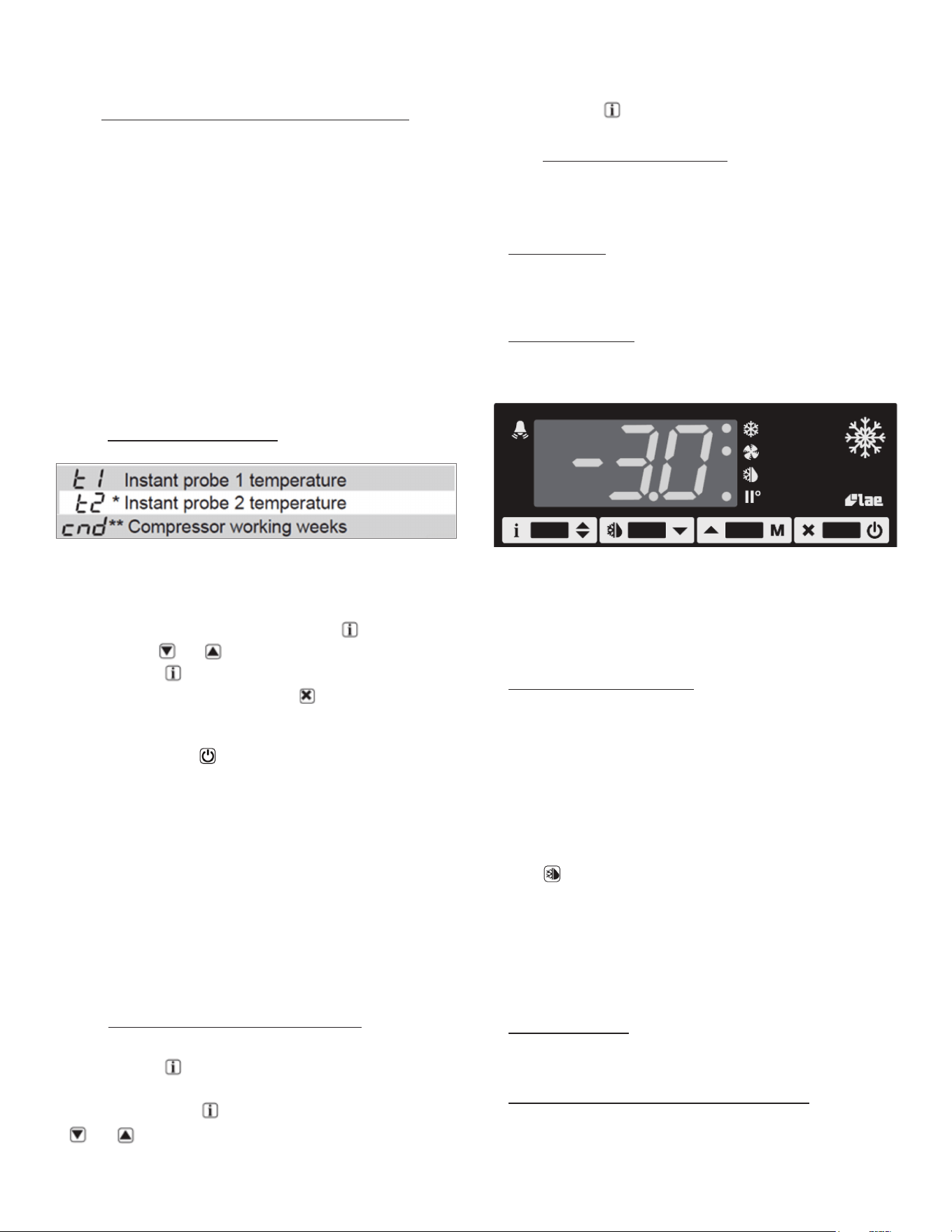
VI. a - INFORMATION MENU
The information available in this menu is:
* displayed only if enabled (see Configuration Parameters)
** displayed only if ACC > 0
Access to menu and information displayed:
• Press and immediately release button .
• With button or select the data to be displayed.
• Press button to display value.
• To exit from the menu, press button or wait for 10 seconds.
Initiate Stand-By:
Keeping the button pressed for 3 seconds allows the
controller to be put on a standby or output control to be
resumed (with SB=YES only).
Locking the Keypad:
The keypad lock avoids undesired, potentially dangerous
operations, which might be attempted when the controller
is operating in a public place. In the INFO menu, set
parameter LOC = YES to inhibit all functions of the buttons.
To resume normal operation of keypad, adjust setting so
that LOC = NO.
VI. b - ADJUSTING CABINET SETPOINT
Setpoint display and modification:
• Press button for at least a half second to display
the setpoint value.
• While keeping the button pressed, use button
or to set the desired value (adjustment is within
the minimum SPL and the maximum SPH limit).
• When button is released, the new value is stored.
VI. c - INITIATING A DEFROST
Automatic defrost:
Defrost starts automatically as soon as the time set with
parameter DFT has elapsed.
• Timed defrost: With DFM = TIM defrosts take place at
regular intervals when the timer reaches the value
of DFT. For example, with DFM = TIM and DFT = 36, a
defrost will take place every 6 hours.
• Optimized defrost: With DFM = FRO the timer is only
increased when the conditions occur for frost to form
on the evaporator, until the time set with parameter
DFT is matched. If the evaporator works at 0°F, defrost
frequency depends on the thermal load and climatic
conditions. With setpoints much lower than 0°F,
defrost frequency mainly depends on the refrigerator
operating time.
• Defrost time count backup: At the power-up, if DFB =
YES, the defrost timer resumes the time count from
where it was left o before the power interruption.
Vice versa, with DFB = NO, the time count re-starts
from 0. In stand-by, the accumulated time count is
frozen.
Manual or remote defrost start:
It’s possible to manually start a defrost, by pressing
button for 2 seconds.
Defrost type. Once defrost has started, Compressor and
Defrost outputs are controlled according to parameter
DTY. If FID = YES, the evaporator fans are active during
defrost.
Defrost termination. The actual defrost duration is
influenced by a series of parameters.
• Time termination: T2 = NO and T3 dierent from 2EU:
the evaporator temperature is not monitored and
defrost will last as long as time DTO.
• Temperature monitoring of one evaporator: T2 = YES
and T3 dierent from 2EU. In this case, if the sensor
T2 measures the temperature DLI before the time DTO
elapses, defrost will be terminated in advance.
VI. CONTROL BASICS
V. CARE AND MAINTENANCE (continued)
VI. CONTROL BASICS (continued)
-9-
VI. CONTROL BASICS (continued)
VI. c - INITIATING A DEFROST (cont’d)
Resuming thermostatic cycle:
When defrost is over, if DRN is greater than 0, all outputs
will remain o for DRN minutes, in order for the ice to melt
completely and the resulting water to drain. Moreover, if
probe T2 is active (T2 = YES), the fans will re-start when
the evaporator gets to a temperature lower than FDD; Vice
versa, if probe T2 is not active (T2 = NO) or after defrost
has come to an end, such condition does not occur by end
of the time FTO, after FTO minutes have elapsed the fans
will be switched on anyway.
Caution: if DFM = NON or C-H = HEA all defrost functions
are inhibited; if DFT = 0, automatic defrost functions are
excluded.
VI. d - CONFIGURATION PARAMETERS
Parameter Configuration:
• To get access to the parameter configuration menu,
press button and for 5 seconds.
• With button or select the parameter to be
modified.
• Press button to display the value.
• By keeping button pressed, use button or to
set the desired value.
• When button is released, the newly programmed
value is stored and the following parameter is
displayed.
• To exit from the setup, press button or wait for 30
seconds.
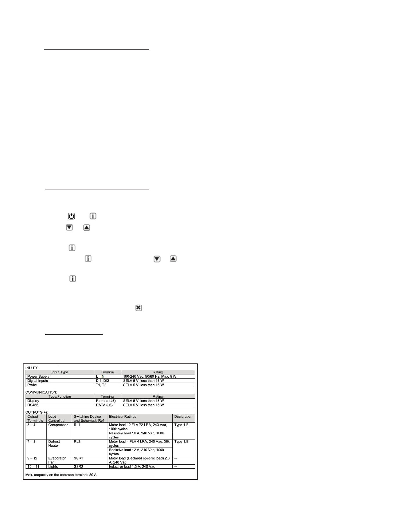
VI. e - TECHNICAL DATA
Power supply: 100-240Vac ±10%, 50/60Hz, 3W
Relay output max loads (240Vac)

-10-
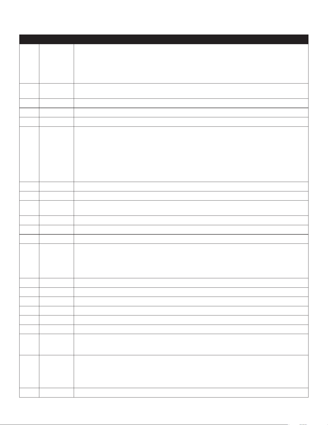
PAR RANGE DESCRIPTION
SPL -58..SPH Minimum limit for SP setting.
SPH SPL...180° Maximum limit for SP setting.
SP SPL... SPH Setpoint (value to be maintained in the room).
C-H REF; HEA Refrigerating (REF) or Heating (HEA) control mode.
HY0 1...10° Thermostat OFF -> ON dierential.
HY1 0...10° Thermostat ON -> OFF dierential.
CRT 0...30min Compressor rest time. The output is switched on again after CRT minutes have elapsed since
the previous switchover. We recommend to set CRT=03 with HY0<2.0°.
CT1 0...30min Compressor/Heater output run when probe T1 is faulty. With CT1=0 the output will always
remain OFF.
CT2 0...30min Compressor/Heater output stop when probe T1 is faulty. With CT2=0 and CT1>0 the output will
always be ON.
Example: CT1=4, CT2= 6: In case of probe T1 failure, the compressor will cycle 4 minutes ON and
6 minutes OFF.
DFM NON;
TIM;
FRO
CRN
Defrost start mode
NON : defrost function is disabled (the following parameter will be FCM).
TIM : regular time defrost.
FRO : the defrost time count is only increased when the conditions occur for frost to form on
the evaporator (optimized time increase).
CRN : defrost is based o of compressor run time (time is based o of DAT).
DFT 0...250 Time interval among defrosts in x10 minutes. When this time has elapsed since the last defrost,
a new defrost cycle is started. Each number is multiplied by 10 minutes. 0-250 indicates 0-2500
minutes.
DAT 0…100 hours Frost accumulation timeout.
DFB NO/YES Defrost timer backup. With DFB=YES, after a power interruption, the timer resumes the count from
where it was left o with ±30 min. approximation. With DFB=NO, after a power interruption, the
defrost timer will re-start to count from zero.
DLI -58...180° Defrost end temperature.
DMD 0…30min Minimum defrost duration.
DTO 1...120min Maximum defrost duration.
DTY OFF; ELE;
GAS
Defrost type
OFF: o cycle defrost (Compressor and Heater OFF). ELE: electric defrost (Compressor OFF and
Heater ON). GAS: hot gas defrost (Compressor and Heater ON).
DSO OFF;
LO;
HI
Defrost start optimization
OFF : no optimization.
LO : defrost waits until the compressor cut-out.
HI : defrost waits until the compressor cut-in.
SOD 0...30 min Start optimization delay.
DPD 0...240sec Evaporator pump down. At the beginning of defrost, defrost outputs (determined by DTY) are
OFF for DPD seconds.
DRN 0...30min Pause after defrost (evaporator drain down time).
VI. CONTROL BASICS (continued)
-11-
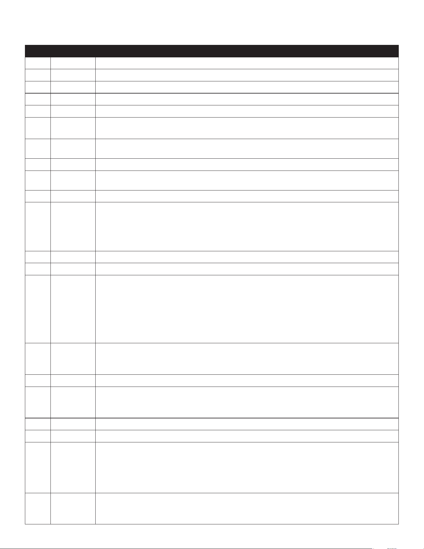
PAR RANGE DESCRIPTION
DDM RT;
LT;
SP;
DEF
Defrost display mode. During defrost the display will show:
RT: the real temperature;
LT : the last temperature before defrost;
SP : the current setpoint value;
DEF : “dEF”.
DDY 0...60min Display delay. The display shows the information selected with parameter DDM during defrost
and for DDY minutes after defrost termination.
FID NO/YES Fans active during defrost.
FDD -58...180° Evaporator fan re-start temperature after defrost.
FTO 0...120min Maximum evaporator fan stop after defrost.
FCM NON;
TMP;
TIM
Fan mode during thermostatic control.
NON : The fans remain ON all the time;
TMP : Temperature-based control. The fans are ON when the compressor is ON. When the
compressor is turned OFF, the fans remain ON as long as the temperature dierence Te-
Ta is greater than FDT. The fans are turned ON again with FDH dierential. (Te = Evaporator
temperature, Ta = Air temperature);
TIM : Timed-based control. The fans are ON when the compressor is ON. When the compressor
is OFF, the fans switch ON and OFF according to parameters FT1, FT2,FT3
FDT -12...0° Evaporator-Air temperature dierence for the fans to turn OFF after the compressor has stopped.
FDH 1...12° Temperature dierential for fan re-start.
Example: FDT = -1, FDH=3. In this case, after the compressor has stopped, the fans are OFF when
Te > Ta - 1 (FDT), whereas the fans are ON when Te < Ta - 4 (FDT-FDH).
FT1 0...180sec Fan stop delay after compressor/heater stop. See Fig. 2
FT2 0...180 Timed fan stop in x10 seconds. With FT2=0 the fans remain on all the time.
FT3 0...180 Timed fan run in x10 seconds. With FT3=0, and FT2 > 0, the fans remain o all the time.
ATM NON;
ABS;
REL
Alarm threshold management.
NON : all temperature alarms are inhibited (the following parameter will be ACC).
ABS : the values programmed in ALA and AHA represent the real alarm thresholds.
REL : the alarm threshold is obtained by the sum of setpoint, thermostat dierential and ALR/
AHR.
ALA -58... 180° Low temperature alarm threshold.
AHA -58... 180° High temperature alarm threshold.
ALR -12... 0° Low temperature alarm dierential. With ALR=0 the low temperature alarm is excluded.
AHR 0... 12° High temperature alarm dierential. With AHR=0 the high temperature alarm is excluded.
ATI T1; T2; T3 Probe used for temperature alarm detection.
ATD 0... 120 min Delay before alarm temperature warning.
ACC 0...52 weeks Condenser periodic cleaning. When the compressor operation time, expressed in weeks, matches
the ACC value programmed, “CL” flashes in the display. With ACC=0 the condenser cleaning warning
is disabled and CND disappears from Info Menu.
IISM NON;
MAN;
ECO;
DI
Switchover mode to second parameter set
NON : inhibition to use the second parameter group (the following parameter will be SB).
MAN : button switches the two parameter groups over.
ECO : automatic switchover to the second parameter group, when ECO conditions are detected.
DI : switchover to the second parameter group when DIx input is on.
IISL -58... IISH Minimum limit for IISP setting.
VI. CONTROL BASICS (continued)
-12-
PAR RANGE DESCRIPTION
IISH IISL... 180° Maximum limit for IISP setting.
IISP IISL... IISH Setpoint in mode 2.
IIH0 1... 10° Thermostat OFF->ON dierential in mode 2.
IIH1 0... 10° Thermostat ON->OFF dierential in mode 2.
IIDF 0...250 Time interval among defrosts in mode 2 in x10 minutes.
IIFC NON; TMP;
TIM
Fan control in mode 2. See FCM.
ECS 1...5 Controller sensitivity for the automatic switchover from Group I to Group II (1=minimum,
5=maximum).
ECS 1…5 Controller sensitivity for the automatic switchover.
EPT 0...240 min Eco pull-down time. Only with IISM=ECO. Group I parameters are used in regulation for at least
EPT minutes. See Fig.3
SB NO/YES Stand-by button enabling.
DSM NON;
ALR;
STP
Door switch input mode:
NON : door switch inhibited
ALR : when DIx=DOR and the digital input is on, an alarm is generated after ADO minutes
STP : when DIx=DOR and the digital input is on, in addition to the alarm, the fans are
immediately stopped and the compressor is stopped after CSD minutes.
DAD 0...30 min Delay before door open alarm warning.
CSD 0...30 min Compressor/heater stop delay after door has been opened.
D1O NON;
DOR;
ALR;
IISM;
RDS
DI1 digital input operation
NON : digital input 1 not active.
DOR : door input.
ALR : when the input is on, an alarm is generated (if AHM=STP, the compressor is stopped and
the defrosts are suspended).
IISM : when the input is on, the controller will use group 2 parameters.
RDS : when the input is on, a defrost is started (remote control).
D1A OPN;
CLS.
DI1 digital input activation.
OPN : on open
CLS : on close
D2O See D1O DI2 digital input operation. See D1O.
D2A OPN;
CLS.
DI2 digital input activation.
OPN : on open
CLS : on close
PSL -58…158 Minimum setpoint adjusted via potentiometer.
PSR 0…15 Range of setpoint adjusted via potentiometer.
LSM NON;
MAN;
ECO;
DI1;
DI2; DI3.
Light control mode
NON : light output not controlled.
MAN : light output controlled through button (if OAx=LGT).
ECO : lights activated/deactivated following the ECO state.
DIx : lights activated/deactivated following the DIx state.
LSA OPN;
CLS
Light activation (only with LSM=ECO or LSM=DIx).
OPN : lights on with DIx open or ECO mode deactivated. CLS : lights on with DIx closed or ECO
mode activated.
VI. CONTROL BASICS (continued)
-13-
VI. CONTROL BASICS (continued)
PAR RANGE DESCRIPTION
OT1 0…600 sec Activation time of OA1
OT2 0…600 sec Pause between OA1 activation
OA1 NON;
LGT;
0-1;
2CU;
2EU;
ALO;
ALC
AUX 1 output operation
NON : output disabled (always o).
LGT : output enabled for light control.
0-1 : the relay contacts follow the on/standby state of controller.
2CU : output programmed for the control of an auxiliary compressor.
2EU : output enabled for the control of the electrical defrost of a second evaporator.
ALO : contacts open when an alarm condition occurs.
ALC : contacts make when an alarm condition occurs.
2CD 0...120 sec Auxiliary compressor start delay. If OAx=2CU the auxiliary output is switched on with a delay
of 2CD seconds after the main compressor has cut-in. Both compressors are turned o at the
same time.
OS1 -12.5..12.5° Probe T1 oset.
T2 NO/YES Probe T2 enabling (evaporator).
OS2 -12.5..12.5° Probe T2 oset.
T3 NON;
DSP;
CND;
2EU
Auxiliary probe T3 operation
NON : probe T3 not fitted.
DSP : temperature T3 to be displayed.
CND : condenser temperature measurement.
2EU : second evaporator temperature measurement.
OS3 -12.5..12.5° Probe 3 oset.
AHM NON;
ALR;
STP;
Operation in case of high condenser alarm
NON : high condenser alarm inhibited.
ALR : in case of alarm, “HC” flashes in the display and the buzzer is switched on.
STP : in addition to the alarm symbols displayed, the compressor is stopped and defrosts are
suspended.
AHT -50...110° Condensation temperature alarm (referred to T3 probe).
TLD 1...30 min Delay for minimum temperature (TLO) and maximum temperature (THI) logging.
TDS T1;
1-2;
T3
Selects the temperature probe to be displayed.
T1 : probe T1
1-2 : the AVG-weighted average between T1 and T2
T3 : probe T3
AVG 0...100% The relative weight of T2 on T1 (if TDS = 1-2)
Example 1: T1 = -5°, T2 = -20°, AVG = 100%. The displayed temperature will be -20° (T1 has no
eect)
Example 2: T1 = -5°, T2 = -20°, AVG = 60%. The displayed temperature will be -14.
SCL 1°C;
2°C;
°F
Readout scale.
1°C : measuring range -50…110°C (0.1°C resolution within -9.9 ÷ 19.9°C interval, 1°C outside)
2°C : measuring range -50 … 110°C
°F : measuring range -55 … 180°F
SIM 0...100 Display slowdown.
ADR 1...255 TRL-002 address for PC communication.
NPR 0…1 Setup programmed.
STT 0…255 Setup traceability.
-14-
VI. f - COMPONENTS AND WIRING DIAGRAM
Indications:
Control Wiring Diagram:
Thermostat output
Fan output
Defrost output
Activation of 2
nd
patameter set
Alarm
Manual activation / Increase button
Exit / Stand-by button
VI. CONTROL BASICS (continued)
-15-
VII. a -TROUBLESHOOTING GUIDE
FIND YOUR PROBLEM HERE REMEDY
1. Condensing unit fails to start.
a.Check if cord & plug has been disconnected.
b.Check control temperature setting.
2. Condensing unit operates for prolonged periods or
continuously.
a.Are doors closing properly?
b.Dirty condenser or filter. Clean properly.
c.Evaporator coil iced. Needs to defrost. See instructions for
setting a manual defrost cycle on section VI.c.
3. Food compartment is too warm.
a.Check door(s) and gasket(s) for proper seal
b.Perhaps a large quantity of warm food has recently been
added or the door was kept open for a long period of
time, in both cases, allow adequate time for the cabinet
to recover its normal operating temperature.
c.Control setting too high, readjust per instructions on
section VI.b.
d.Check that condensing coil is clean.
4. Food compartment is too cold.
a.Perhaps a large quantity of very cold or frozen food
has recently been added. Allow adequate time for the
cabinet to recover its normal operating temperature.
b.Adjust the control to a warmer setting, see section VI.b.
5. Condensation on the exterior surface.
a.Check door alignment and gaskets for proper seal.
b.Condensation on the exterior surface of the unit is
perfectly normal during periods of high humidity.
6. Compressor hums but does not start. a.Call for service.
7. No power to unit
a.Check if cord & plug has been disconnected.
b.Check power supply breaker.
VII. TROUBLESHOOTING GUIDE
-16-
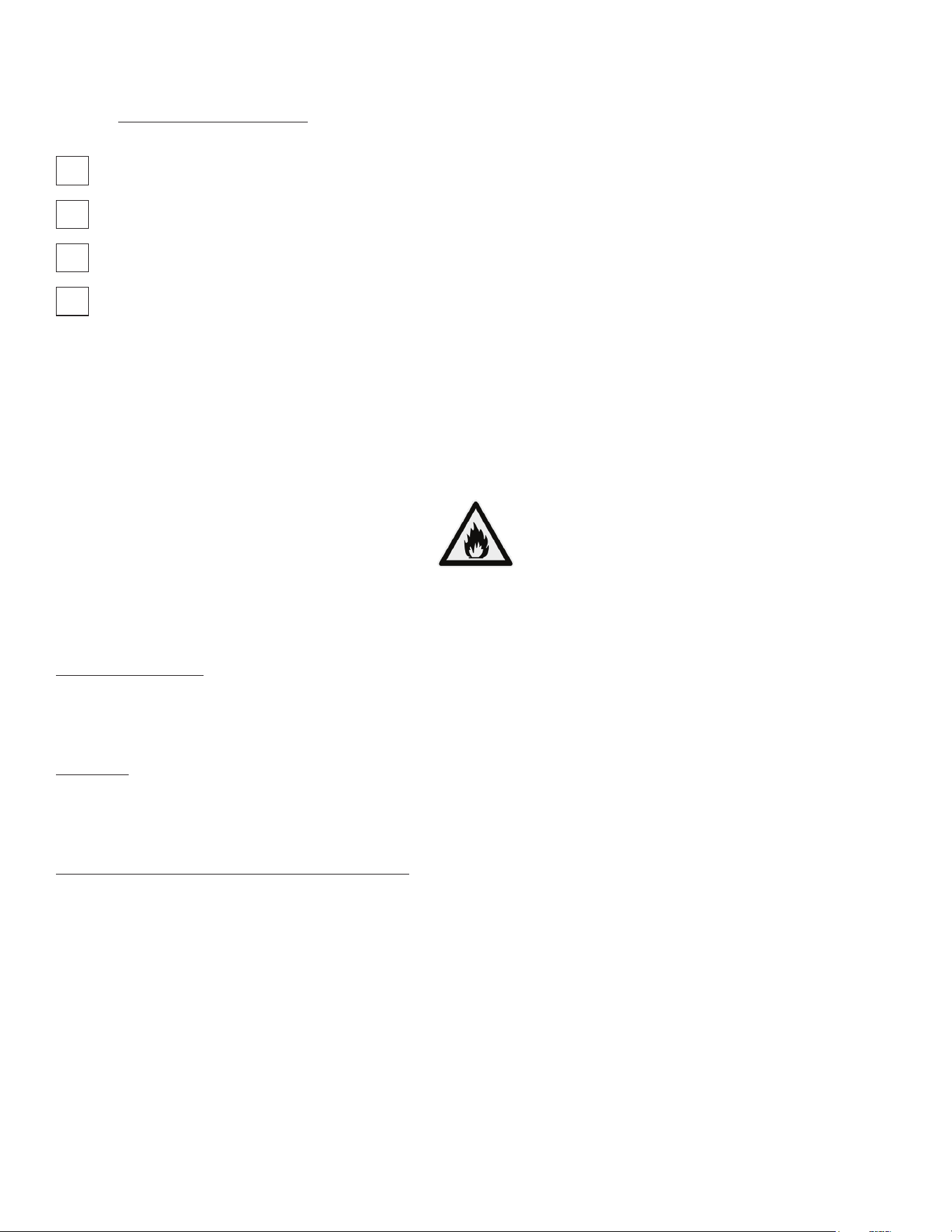
VIII. a - SERVICE INFORMATION
Before calling for service, please check the following:
Is the electrical cord plugged in?
Is the fuse OK or circuit breaker on?
Is the condenser coil clean?
Is the power switch on?
If after checking the above items and the unit is still not operating properly, please contact an authorized Traulsen service
agent:
4401 Blue Mound Road Fort Worth, TX 76106
(800) 825-8220.
Traulsen reserves the right to change specifications or discontinue models without notice.
This appliance is marked with the ISO 7010-W021 warning label to indicate the presence of FLAMMABLE REFRIGERANTS.
Prior to beginning work on systems containing FLAMMABLE REFRIGERANTS, safety checks are necessary to ensure that
the risk of ignition is minimized.
VENTILATED AREA
Ensure that the area is in the open or that it is adequately ventilated before breaking into the system or conducting any
hot work. A degree of ventilation shall continue during the period that the work is carried out. The ventilation should
safely disperse any released refrigerant and preferably expel it externally into the atmosphere.
CABLING
Check that cabling will not be subject to wear, corrosion, excessive pressure, vibration, sharp edges, or any other
adverse environmental eects. The check shall also take into account the eects of aging or continual vibration from
sources such as compressors or fans.
DETECTION OF FLAMMABLE REFRIGERANTS
Under no circumstances shall potential sources of ignition be used in the searching for or detection of refrigerant
leaks. A halide torch (or any other detector using a naked flame) shall not be used.
The following leak detection methods are deemed acceptable for all refrigerant systems. Electronic leak detectors may
be used to detect refrigerant leaks but, in the case of FLAMMABLE REFRIGERANTS, the sensitivity might not be
adequate, or might need recalibration. (Detection equipment shall be calibrated in a refrigerant-free area.) Ensure that
the detector is not a potential source of ignition and is suitable for the refrigerant used. Leak detection equipment
shall be set at a percentage of the LFL of the refrigerant and shall be calibrated to the refrigerant employed, and the
appropriate percentage of gas (25 % maximum) is confirmed.
Leak detection fluids are also suitable for use with most refrigerants but the use of detergents containing chlorine shall
be avoided as the chlorine can react with the refrigerant and corrode the copper pipe-work.
VIII. SERVICE/WARRANTY INFORMATION
-17-
VIII. SERVICE/WARRANTY INFORMATION (continued)
NOTE: Examples of leak detection fluids are
• bubble method
• fluorescent method agents
If a leak is suspected, all naked flames shall be removed/extinguished.
If a leakage of refrigerant is found which requires brazing, all of the refrigerant shall be recovered from the system,
or isolated (by means of shut o valves) in a part of the system remote from the leak. Removal of refrigerant shall be
according to the removal & evacuation section below.
REMOVAL & EVACUATION
When breaking into the refrigerant circuit to make repairs- or for any other purpose - conventional procedures shall
be used. However, for flammable refrigerants it is important that best practice be followed, since flammability is a
consideration. The following procedure shall be adhered to:
a) safely remove refrigerant following local and national regulations;
b) purge the circuit with inert gas;
c) evacuate
d) purge with inert gas;
e) open the circuit by cutting or brazing.
The refrigerant charge shall be recovered into the correct recovery cylinders if venting is not allowed by local and
national codes. For appliances containing flammable refrigerants, the system shall be purged with oxygen- free
nitrogen to render the appliance safe for flammable refrigerants. This process might need to be repeated
several times. Compressed air or oxygen shall not be used for purging refrigerant systems .
For appliances containing flammable refrigerants, refrigerants purging shall be achieved by breaking the vacuum in
the system with oxygen-free nitrogen and continuing to fill until the working pressure is achieved, then venting to
atmosphere, and finally pulling down to a vacuum. This process shall be repeated until no refrigerant is within the
system (optional for A2L). When the final oxygen-free nitrogen charge is used, the system shall be vented down to
atmospheric pressure to enable work to take place.
Ensure that the outlet for the vacuum pump is not close to any potential ignition sources and that ventilation is
available.
VIII. b - SPARE PARTS INFORMATION
To purchase replacement parts or to speak to service support for Traulsen units please contact our Ft. Worth facility by
phone at 800-825-8220 or fax to 817-740-6748 (parts) or 817-740-6757 (service).
Note: When calling for spare parts or service support, please make sure you have model and serial number of unit available.
4401 Blue Mound Rd.
Ft. Worth, TX 76106
800-825-8220
Input Power (ELIN) - FOR INDOOR USE ONLY
115-208/230V ~ 60Hz 8.0A (8,0A)
MODEL:
MODELO:
MODELE:
RDT232WUT-FHS
S/N: T25364A14
REFRIGERANT / REFRIGERANTE / RÉFRIGÉRANT
SYS1 (REFM): R-134a 8.4oz 238.1 g (238,1 g)
Hi Press. (PRESH): 500psi 3.45 MPa (3,45 Mpa)
Lo Press. (PRESL): 250 psi 1.72 Mpa (1,72 Mpa)
SYS2 (REFA): R-404a 12.5oz 354.4g (354,4g)
Hi Press. (PRESH): 500psi 3.45MPa (3,45MPa)
Lo Press. (PRESL): 250psi 1.72Mpa (1,72Mpa)
(Symbol 1)
(Alt Safety / Other
1)
(Symbol 2)
(Alt. San / Other 2)
(Symbol 3)
(Alt. En. / Other 3)
(Symbol 4)
(WEEE)
(Symbol 5)
(Safety)
(Symbol 6)
(Sanitaon)
(Symbol 7)
(Energy)
(Symbol 8)
(Customer QR
Code / Other 4)
Device/Part Number: PartNum (UL/NSF Notes)
SCAN FOR SERVICE INFO
COMPONENTS / COMPOSANTS / COMPONENTES
COMP AMPS: EVAP FAN AMPS:
COND FAN AMPS: LIGHT WATTS:
DEF HTR AMPS: CTRL AMPS:
DOOR HTR AMPS: MIN AMPS:
MAX AMPS:
370-60297-00 REV.A 11/20/14
VIII. c - WARRANTY REGISTRATION:
The warranties for your new Traulsen unit may be registered with us by by completing warranty information online,
via our website www.traulsen.com. Click on the Product Registration text at the footer of the home page. You may also
register your product by calling us directly at 800-825-8220.
Model Number
Serial Number

-18-
NOTES

Form Number: TR36443 | Part Number: 375-60363-00 (Rev. G) | Revision Date: 01/26
Traulsen © All Rights Reserved
4401 Blue Mound Road Fort Worth, Texas 76106 (USA)
Phone: 800.825.8220 | Service Fax: 817.740.6757 | E-mail: service@traulsen.com | Website: traulsen.com