NOTE: This manual is intended for use with the above referenced equipment manufactured after July 1, 2025. To obtain
a copy of the correct Owner's Manual to support the same product manufactured prior to this date, please contact
Traulsen's service department at (800) 825-8220.
OWNER’S MANUAL
R-Series
Reach-in, pass-thru, roll-in & roll-thru refrigerators
Reach-in & roll-in freezers
Reach-in refrigerator/freezer dual temperature units
Reach-in, pass-thru, roll-in & roll-thru hot food holding cabinets
Hours Of Operation: Monday - Friday 7:30 a.m. - 4:30 p.m.
(CST)
4401 Blue Mound Road Fort Worth, Texas 76106 (USA)
Phone: 800.825.8220 | Service Fax: 817.740.6757 | E-mail: [email protected] | Website: traulsen.com
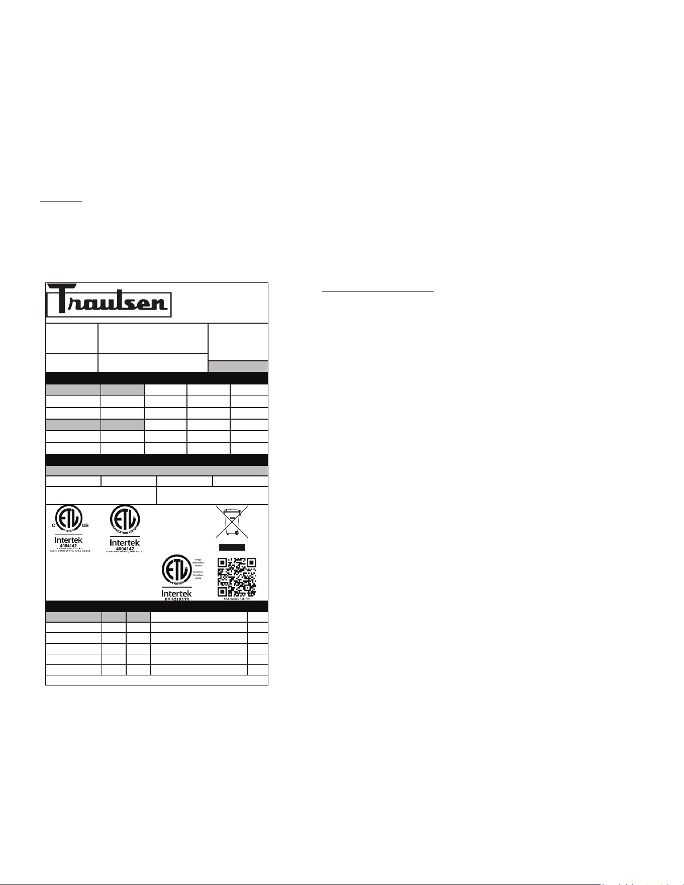
Table of Contents
I. The Serial Tag
II. Receipt Inspection Page 2
III. Installation Page 2
IV. Operation Page 5
-1-
V. Care & Maintenance Page 5
VI. Control Basics Page 7
VII. Troubleshooting Guide Page 11
VIII. Service/Warranty Page 12
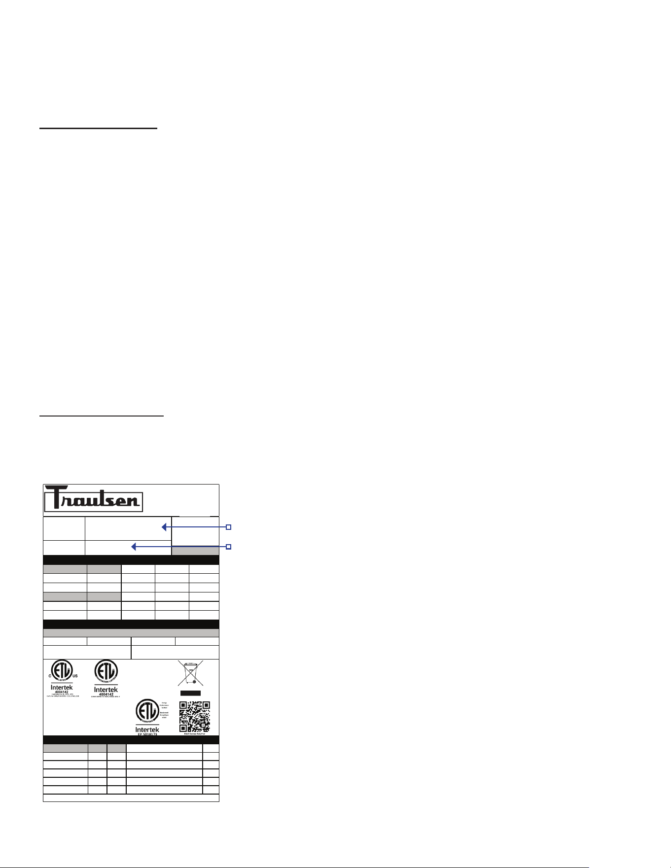
I. The Serial Tag
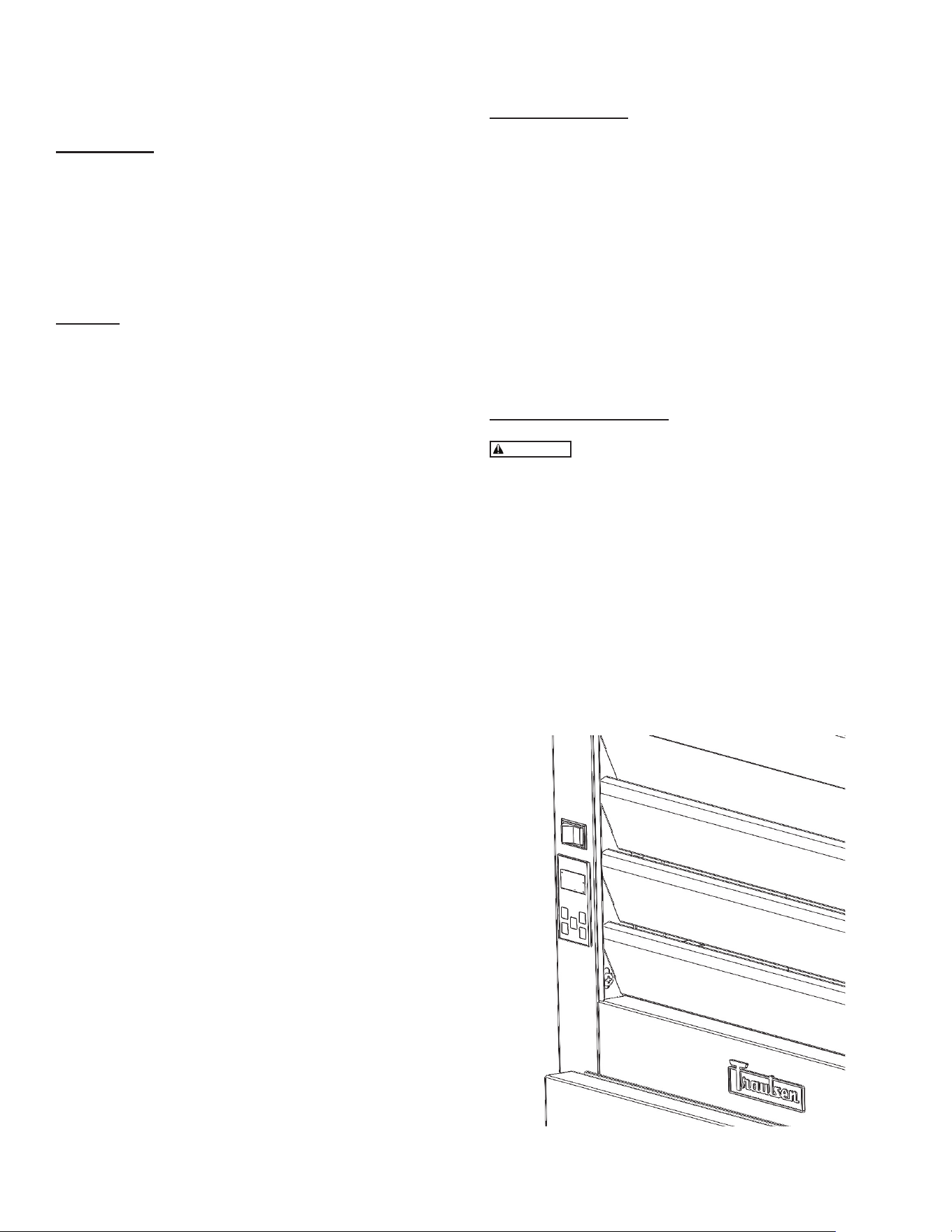
Location:
The serial tag is a permanently axed label on which is recorded vital electrical and refrigeration data about your Traulsen
product, as well as the model and serial number. This tag is located in the upper right interior compartment on all reach-in/
pass-thru and roll-in/roll-thru refrigerator, freezer and dual-temp models. For hot food models, this tag is located on the top
of the unit behind the louvers to protect it from the heat.
Reading the Serial Tag
• Serial = The permanent ID# of your Traulsen
• Model = The model # of your Traulsen
• Refrigerant SYS1 = Refrigerant Type & Charge
• Refrigerant SYS2 = Refrigerant Type & Charge
• Volts = Voltage
• Hertz = Cycle
• Total Current = Maximum amp draw
• Minimum Circuit Amps = Minimum circuit ampacity
• Lights = Light wattage
• Heaters
• Refrigerant = Refrigerant type used
• Design Pressure = High & low side operating
pressures and refrigerant charge
• Agency Labels = Designates agency listings
ITW Food Equipment Group, LLC
North American Refrigeration
4401 Blue Mound Rd.
Ft. Worth, TX 76106
800-825-8220
MODEL:
MODELO:
MODELE:
RDT232WUT-FHS
SERIAL NUMBER:
25F02060
SCAN FOR SERVICE INFO
REFRIGERANT / REFRIGERANTE / RÉFRIGÉRANT
SYS1 (REFM):
R-290
3.80 OZ
107.71 g
107,71 g
Hi Press. (PRESH):
360.00 psi
2,482.11 kPa
2.482,11 kPa
Lo Press. (PRESL):
130.00 psi
896.32 kPa
896,32 kPa
SYS2 (REFA):
R-290
3.00 OZ
85.04 g
85,04 g
Hi Press. (PRESH):
460.00 psi
3,171.59 kPa
3.171,59 kPa
Lo Press. (PRESL):
140.00 psi
965.27 kPa
965,27 kPa
Input Power (ELIN) - FOR INDOOR USE ONLY
Voltage
Hertz
Phase
Total Amps
115 ~
60
1
12.60
Device/Part Number:
RD232W-291
Device/Part Notes:
COMPONENTS / COMPOSANTS / COMPONENTES
1
2
MAX OVER CURRENT PROTECTION (A):
COMP AMPS:
MIN CIRCUIT IN AMPS:
COND FAN AMPS:
DOME LIGHT WATTS:
11
EVAP FAN AMPS:
DISPLAY LIGHT WATTS:
CONTROL AMPS:
DOOR HEATER WATTS:
DEF HEATER WATTS:
B/TMCE HTR WATTS:
370-60297-00 REV. D 01/15/2024
-2-
To remove the wooden pallet, rst, if at all possible, we sug-
gest that the cabinet remain bolted to the pallet during all
transportation to the point of nal installation. The bolts can
then be removed with a 3/4” socket wrench. Avoid laying the
unit on its front, side or back for removal of the pallet.
NOTE: DO NOT LAY THE UNIT ON ITS SIDE DURING
TRANSPORTATION OR INSTALLATION.
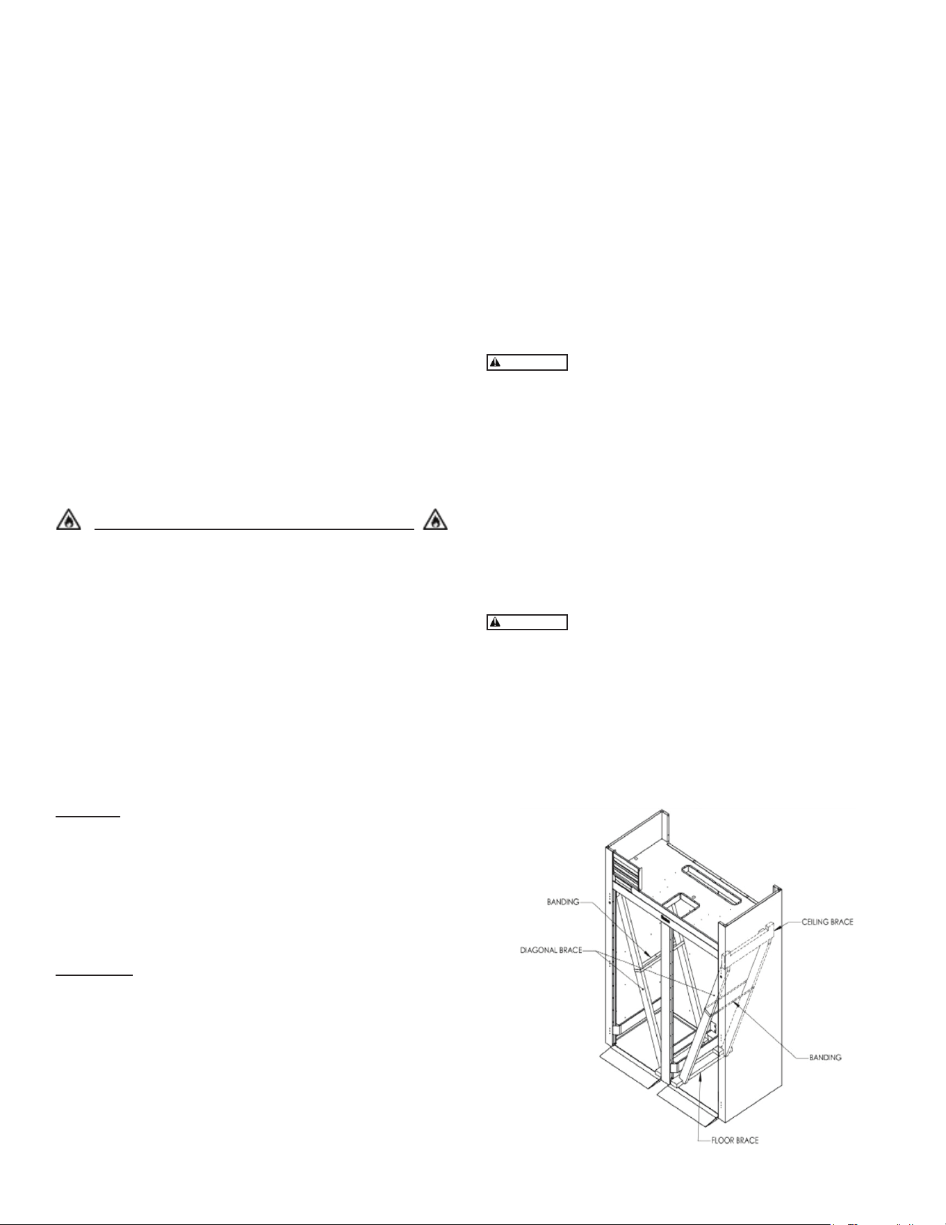
Roll-thru models also include special interior wood bracing,
intended to protect the cabinet during shipment. This bracing
should under no circumstances be removed prior to the unit
being installed in its nal location.
Read and review these instructions, in their
entirety, BEFORE attempting to disassemble and remove
the interior bracing.
If either of the diagonal or upper ceiling braces are dropped,
they could cause personal injury or damage to the equipment.
To disassemble the bracing, rst open the doors and care-
fully remove the banding that holds the two diagonal braces
together.
To disassemble the bracing, rst open the doors and care-
fully remove the banding that holds the two diagonal braces
together.
The diagonal braces will now be loose and can
fall out of position and possibly permit the ceiling corner brace
to fall.
Carefully remove one diagonal brace while supporting the
ceiling corner brace, so that it does not fall (see gure 1).
Next, remove the ceiling brace, the remaining diagonal brace,
and lastly the oor brace - then discard. Repeat as necessary
for each section of the unit.
II. Receipt Inspection
All Traulsen products are factory tested for performance and
are free from defects when shipped. The utmost care has
been taken in crating this product to protect against damage
in transit. All interior ttings have been carefully secured and
the legs or casters are boxed and strapped inside to prevent
damage. Door keys will be attached to the handle with a
nylon strip. The handle is protected by an easily removable
nylon netting.
You should carefully inspect your Traulsen unit for damage
during delivery. If damage is detected, you should save all
the crating materials and make note on the carrier’s Bill Of
Lading describing the damage. A freight claim should be led
immediately. If damage is subsequently noted during or im-
mediately after installation, contact the respective carrier and
le a freight claim. There is a ve (5) day limit to le freight
damage with the carrier. Under no condition may a damaged
unit be returned to Traulsen without rst obtaining written
permission (return authorization). You may contact Hobart/
Traulsen customer care at 800-333-7447 to request a return.
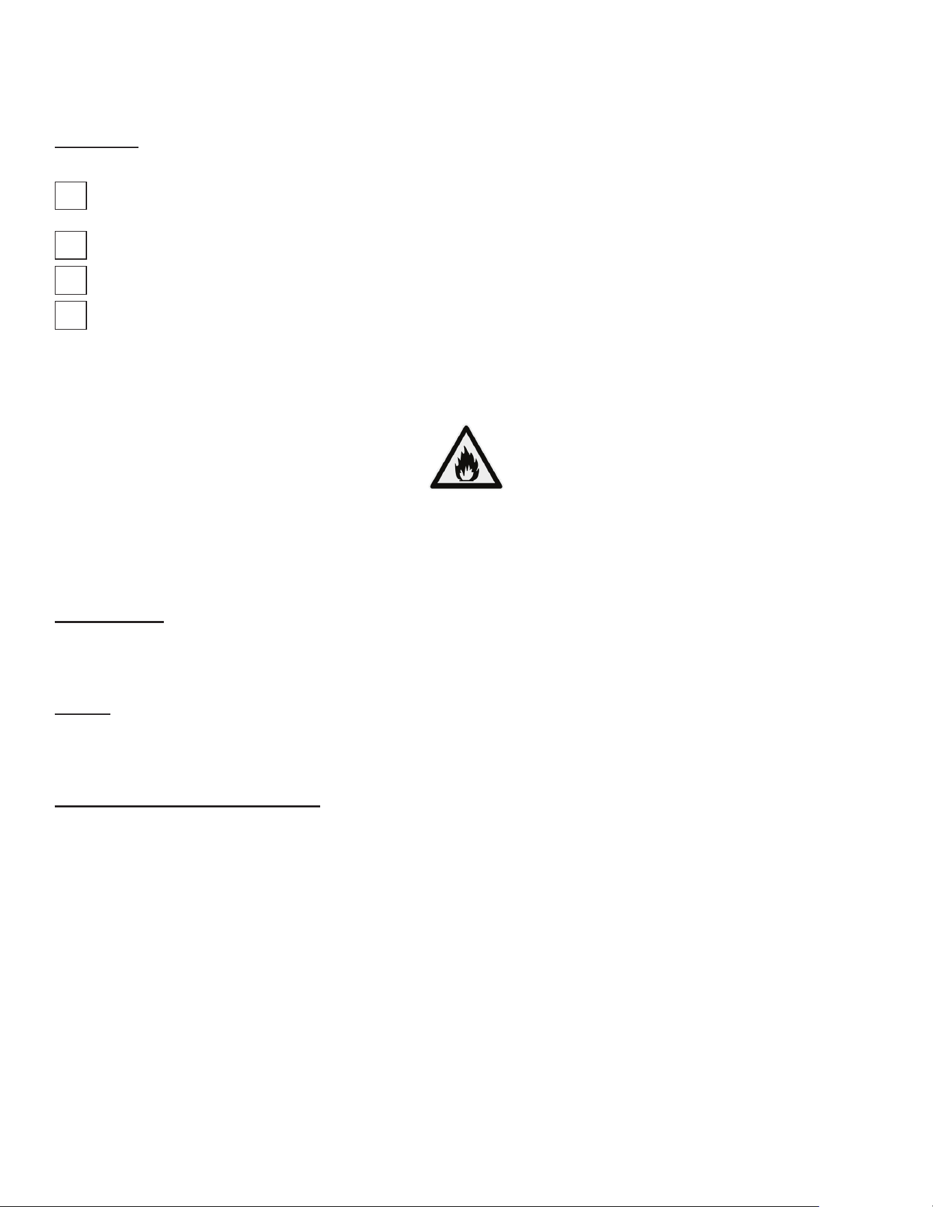
Systems Using Refrigerant R-290 (Propane)
Traulsen has selected propane as the refrigerant for many
of their products. In addition to its low global warming
potential and impact on the environment, propane is an
ideal refrigerant. It is a ammable refrigerant, however,
which is why you will see a “ammable refrigerant” sticker
on applicable products. Traulsen products using propane
as the refrigerant are ETL approved and are safe to use in
accordance with this Owner’s Manual and general industry
practices for commercial cooking environments. Please
check with local codes or regulations for any restrictions to
products using hydrocarbon refrigerants.
III. Installation
Location
Select a proper location for your Traulsen unit, away from
extreme heat or cold. Allow enough clearance between the
unit and the side wall in order to make use of the door stay
open feature at 120° (self-closing feature operates up to
90°). The door(s) must be able to open a minimum of 90° in
order to make use of the maximum clear door width available.
Packaging
All Traulsen units are shipped from the factory bolted to a
sturdy wooden pallet and packaged in a durable cardboard
container. The carton is attached to the wooden skid with the
use of large staples. These should rst be removed to avoid
scratching the unit when lifting o the crate.
Most exterior stainless-steel surfaces have a protective
vinyl covering to prevent scratching during manufacturing,
shipping and installation. After the unit is installed in place of
service, remove and discard the covering from all surfaces.
gure 1
WARNING
WARNING
WARNING
-3-
Installing Legs or Casters
6” High stainless steel legs are supplied standard for all
Traulsen R- Series units. Casters in lieu of legs are available
as an optional accessory for the same models. These are
shipped from the factory packed inside a cardboard box
which is strapped to one of the shelves. Remove the nylon
strap and open the box, it should contain either four (4) legs
or four (4) casters and sixteen (16) bolts.
THE CABINET MUST BE BLOCKED AND
STABLE BEFORE INSTALLING LEGS OR CASTERS.
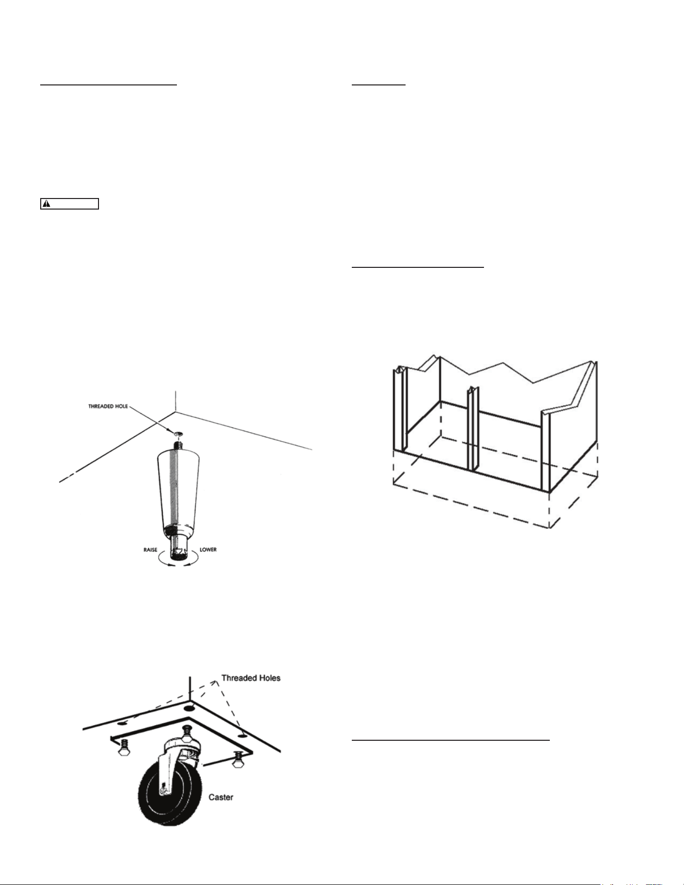
To install the legs or casters, rst raise and block the reach- in
a minimum of 7” from the oor. For installing legs, thread the
legs into the threaded holes on the bottom of the cabinet (see
gure 2). Be certain that all legs are tightly secured (legs and
casters should be tightened to 300 inch/pounds, max). When
the unit is set in its nal position, it is important for proper
operation that the unit be level. The legs are adjustable for
this purpose; turn the bottom of the leg counter- clockwise to
raise it, clockwise to lower it. Level the unit from front to back
as well as side to side in this manner, using a level placed in
the bottom of the cabinet.
Please note that Traulsen units are not designed to be moved
while on legs. If the unit requires moving, a pallet jack or
forklift should be used to prevent damage. For installing cast-
ers, the casters are “plate” type, and require the use of four
(4) bolts each to secure them rmly to the cabinet bottom
at each corner (see gure 3). The caster bolts are tightened
using a 1/2” socket wrench.
gure 2
gure 3
Shelf Pins
The unit is supplied with shelves and shelf pins installed.
Check all shelf pins to assure they are tightened down as
they may have come loose during shipping. Rotate the pins
clockwise until they are secured against the side of the
cabinet.
Shelf Load and Deection
• Maximum weight per shelf: 120 lbs
• Maximum weight per section: 250 lbs
Slight shelf deection under load is normal and acceptable.
Shelving complies with applicable requirements of UL 60335.
Roll-in Model Installation
Roll-in cabinets set on the oor require the oor area to be
at and level. In addition, after the cabinet is set in place,
sealant should be used around the perimeter of the base to
comply with National Sanitation Foundation requirements
(see gure 4). After sealing the unit, the enclosed ramp should
then be installed.
A stainless-steel threshold ramp(s) is included to facilitate roll-
in racks. It is shipped wrapped in brown paper and secured
to the rack guides inside the cabinet. To secure it in place,
remove the two thumb screws in the breaker strip near the
bottom door opening. Next, loosen the thumb screws located
along the oor at the threshold. Place the ramp(s) on top of
the loosened thumb screws and secure tabs on each end to
breaker strips with thumb screws previously removed. After
installing the ramp(s), it too should be sealed to the oor.
Bumper strips are secured to the back of roll-in models with
thumb screws. Loosen these and make them nger tight to
conform with the requirements of the National Sanitation
Foundation (NSF).
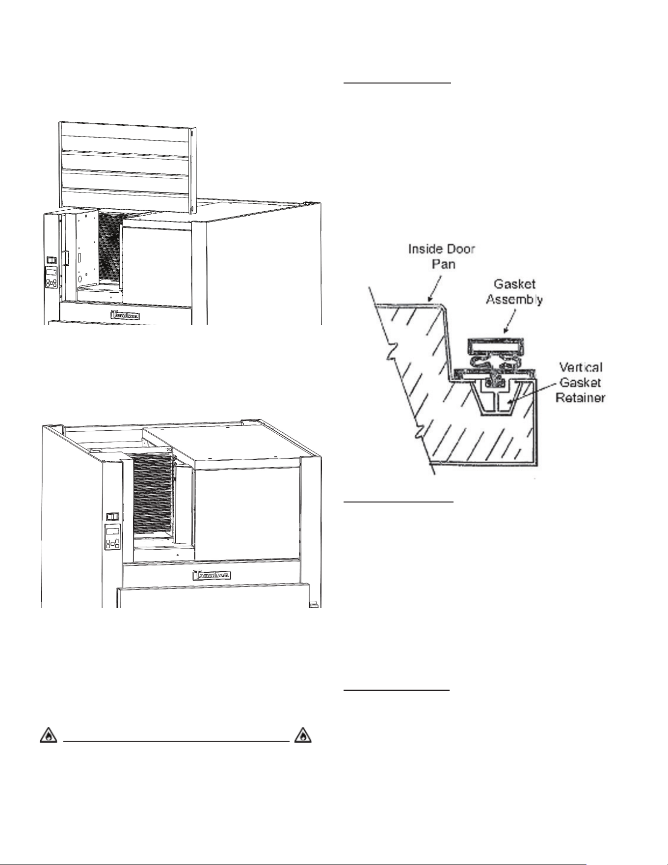
Installing the Condensate Evaporator
A condensate evaporator is normally supplied on all self-
contained models (remote models require provision of either
a oor drain or an optional condensate evaporator). On
those models supplied with a top-mounted evaporator coil
compartment, the condensate evaporator is also secured
to the top of the cabinet. Check that the condensate pan is
properly located underneath the drain tube.
gure 4
Cord & Plug
Most self-contained models are supplied with a cord & plug
attached. It is shipped coiled at the top of the cabinet, secured
by a nylon strip. For your safety and protection, all units
supplied with a cord and plug include a special three-prong
grounding plug on the service cord. Select only a dedicated
electrical outlet with grounding plug for power source.
NOTE: Do not under any circumstances, cut or remove the
round grounding prong from the plug, or use an extension
cord.
Power Supply
The supply voltage should be checked prior to connection
to be certain that proper voltage for the cabinet wiring is
available (refer to the serial tag to determine correct unit
voltage). Make connections in accordance with local electrical
codes. Use qualied electricians.
Use of a separate, dedicated circuit is required. Size wiring
to handle indicated load and provide necessary overcurrent
protector in circuit (see amperage requirements on the unit’s
serial tag).
Clearance
In order to assure optimum performance, the condensing
unit of your Traulsen unit MUST have an adequate supply
of air for cooling purposes. Therefore, the operating location
must either have a minimum of 12” clearance overhead of
the condensing unit or allow for unrestricted air ow at the
back of the unit. Clearance of at least 12” above is requiredin
order to perform certain maintenance tasks.
-4-
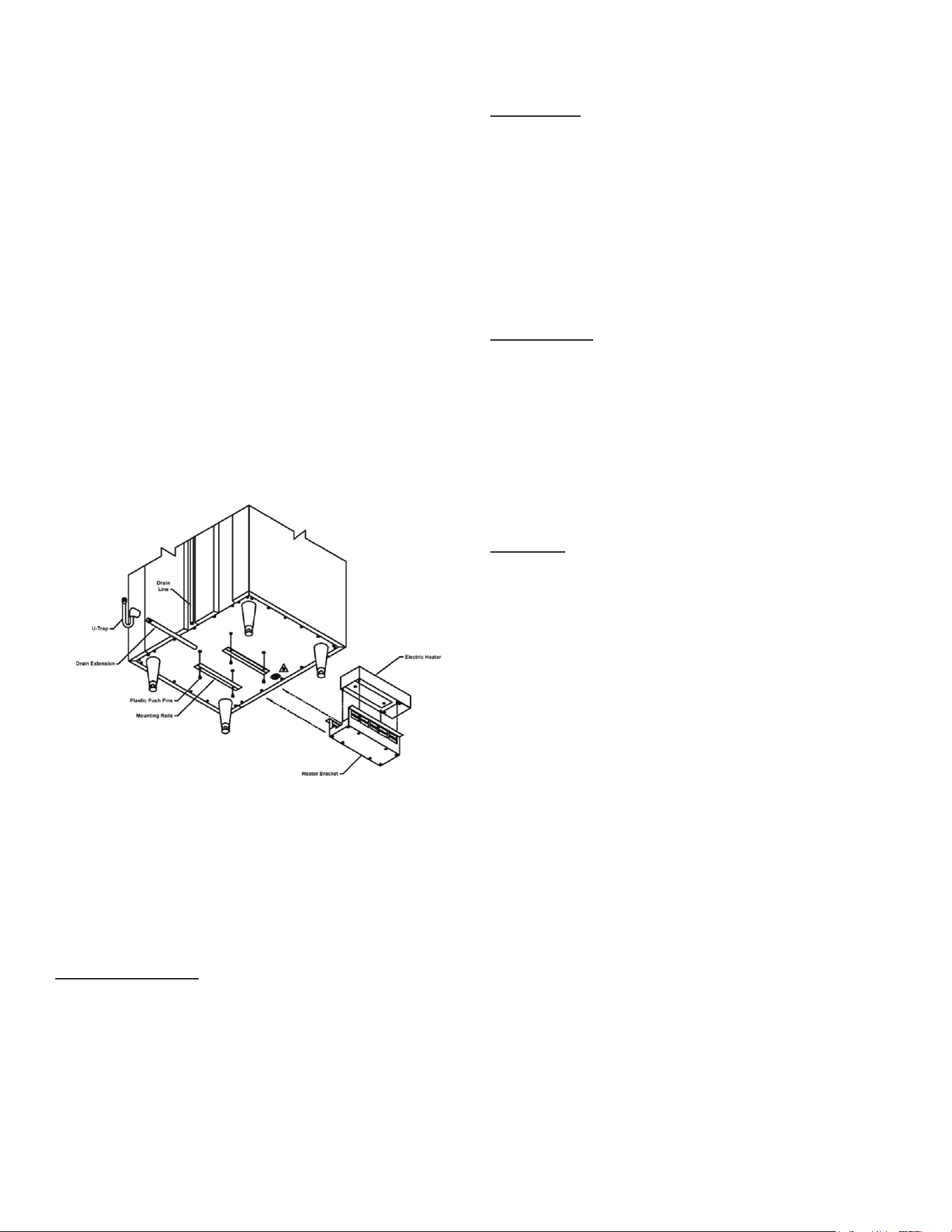
NOTE: Some models, such as single section dual- tempera-
ture refrigerator/freezers, are supplied with a bottom-mounted
condensate evaporator. This is shipped in a cardboard carton
secured to the cabinet interior and must be properly installed
prior to use (see instructions supplied with the condensate
evaporator).
1. After the cabinet has been uncrated and the legs/ casters
attached, you must install the bottom-mounted condensate
evaporator (see gure 5).
2. Locate the four (4) holes on the exterior bottom towards
the rear of the cabinet.
3. Using the provided 10-32 screws, attach the mounting
rails to the bottom, (the folded ange is to be turned up and
be towards the drain line).
4. Slide condensate pan into the mounting rails.
5. Screw the “U-Trap” on to the drain line located on the rear
of the cabinet.
6. Screw the drain extension into the “U-Trap”.
NOTE: The use of the “U-TRAP” supplied is required. Failure
to use this component may allow cold air to migrate down the
drain line, resulting in condensation on the rear of the cabinet.
A remote model is normally supplied congured for conden-
sate to be run to a oor drain unless purchased with a con-
densate evaporator. The installer is responsible for making
the required extension to the oor drain in accordance with
good practice and local regulations.
Remote Installation
Remote models are supplied without compressors, solenoid
valves, etc. The correct voltage, amp listing and refrigerant
are listed on the unit’s serial tag. It is the responsibility of the
installer to specify and supply the correct size compressor(s)
based upon this information and on-site requirements.
Refrigerant line installation must be done in accordance with
good practice and local regulations. See section the previous
section for information concerning condensate removal for
remote models.
gure 5
IV. Operation
Refrigerators
Neither refrigerators nor freezers require manual defrosting.
During normal operation, a refrigerator continuously
circulates cool air (34-38°F) across the evaporator coil. A
defrost cycle occurs every 8 hours to melt any frost which
may have accumulated on the coil. The control will display
the cabinet temperature when the defrost started and activate
a LED with the defrost symbol on the control display.
Freezers
During normal operation, the freezer continuously circulates
below-freezing cabinet air across the evaporator coil to
maintain consistent product temperatures. Over time, frost
may accumulate on the evaporator coil and must be removed
to ensure ecient operation. The freezer is equipped with
Predictive Defrost™, an intelligent, demand-based defrost
system. Unlike traditional timer-based defrost programs,
the smart controller continuously monitors real-time air
temperature and humidity conditions inside the cabinet. A
defrost cycle is initiated only when necessary, based on
actual operating conditions.
This adaptive approach replaces xed, scheduled defrost
intervals with a responsive system that automatically adjusts
to usage patterns and environmental conditions.
The control will display the cabinet temperature when the
defrost started and activate a LED with the defrost symbol
on the display (see gure 13 on page 8). The electric heater
(attached to the coil) is energized. When a temperature
sensor axed to the coil senses 45°F (models with electric
defrost), the coil is fully defrosted and the compressor
operation is resumed, defrost heaters are automatically
turned o. The coil fans are delayed from starting at the
termination of a defrost cycle. Fan operation is automatically
resumed, or they can also be started by a time or temp delay
(whichever comes rst). In case of temp delay, it uses the
same coil sensor and starts at 32°F. The total refrigeration
system operation is then resumed.
During freezer defrost operation, heat is conned to the
coil enclosure to prevent any signicant rise in temperature
within the food zone. The fan delay controls function upon
termination of a defrost cycle is two-fold. First, to prevent
blowing warm air into the food storage area. Second, to
prevent any condensation on the defrost coil from being blown
into the food storage area. The Smart Control is set from the
factory to terminate defrost at 30 minutes in the event of a
sensor failure. This setting should never be tampered with,
without rst consulting the factory.
-5-
Hot Food Cabinets
Hot food cabinet operation is governed by the Smart
Control™, which controls the ON/OFF operation of the strip
heaters. The control can bet set to maintain any operational
temperature between 130-180° F (in 1 degree increments).
Hot food cabinets are delivered from the factory with the
control set to the “OFF” position. Follow the instructions in
section “VI. The Control” to get started.
NOTE: A vent is included at the top of all hot food cabinets.
The vent opening is factory set and secured for best posi-
tion. Be certain to make sure this vent is kept free of any
obstruction.
V. Care & Maintenance
Cleaning the Condenser
Disconnect the electrical power supply before
cleaning any parts of the unit.
The most important thing you can do to insure a long, reli-
able service life for your Traulsen is to regularly clean the
condenser coil.
The condensing unit requires regularly scheduled cleaning
to keep the condenser clean of lint and dust accumulation.
Keeping the condenser clean allows the cabinet to operate
more eciently and use less energy.
To clean the condenser, rst disconnect electrical power to
the cabinet and lift up the front louver assembly. To lift this,
remove the two screws located on both sides at the bottom
of the louver assembly (gure 7).
WARNING
gure 7
-6-
Once the screws are removed, the panel can be pivoted
upwards allowing full access to the front facing condenser
(see gure 8).
Vacuum or brush any dirt, lint or dust from the nned con-
denser coil, the compressor and other cooling system parts
(see gure 9). If signicant dirt is clogging the condenser ns,
use compressed air to blow this clear. Lower louver assembly
and replace the screws to hold it in place.
Most Traulsen R-Series models come with a StayClear™
condenser coil with a wide-nned design. The StayClear coil
does not require regularly scheduled cleanings but should be
cleaned every 6 months or when the wide-nned coil presents
a certain level of obstruction of signicant dirt on the ns. If
the StayClear Condenser requires cleaning, follow the same
steps for cleaning the nned condenser.
Systems Using Refrigerant R-290 (Propane)
Remove any ignition source (arc, ame, heat) before cleaning
the condenser coil. If the condenser coil is inadvertently
damaged during cleaning to the point of causing a refrigerant
leak, immediately ventilate the area and call for service.
Gasket Replacement
To remove the gasket to be replaced, grasp it rmly by one
corner and pull it out. Before attempting to install a new
gasket, both the unit and the gasket itself must be at room
temperature. Insert the four corners rst by using a rubber
mallet (or hammer with a block of wood). After the corners
are properly inserted, work your way toward the center from
both ends by gently tapping with a mallet until the gasket is
completely seated in place (see gure 10).
NOTE: The gasket may appear too large, but if installed as
indicated above, will slip into place.
Cleaning the Exterior
Exterior stainless-steel should be cleaned with warm water,
mild soap and a soft cloth. Apply with a dampened cloth
and wipe in the direction of the metal grain. Avoid use of
strong detergents and gritty, abrasive cleaners as they may
tend to mar and scratch the surface. Do NOT use cleansers
containing chlorine- this may promote corrosion of the
stainless-steel.
Care should be taken to avoid splashing the unit with
water, containing chlorinated cleansers, when mopping the
oor around the unit. For stubborn odor spills, use baking
soda and water (mix 1 tablespoon baking soda : 1 pint water
ratio).
Cleaning the Interior
Interior stainless-steel should be cleaned by using the baking
soda/water mixture described in the previous section. Use the
mixture on breaker strips as well as door gaskets. All interior
ttings are removable without tools to facilitate cleaning.
gure 8
gure 9
gure 10
-7-
Adjusting the Shelves
For shelves mounted on pins, rst select the desired location
and remove the white plastic covers in the interior back and
sides by rotating them counterclockwise. Remove the shelf
pins by rotating them counterclockwise. Install the pins in the
desired location by rotating clockwise. Make sure the pin is
securely tightened. Do not over tighten. Slide the shelf into
its new position and replace the white plastic covers into the
holes vacated by the shelf pins.
Replacing the Light Bulb
All Traulsen R-Series models are supplied with LED lighting.
Optional tube style display lighting is available.
The standard LED bar is 115 or 230 volts. It is mounted at
the top front of the cabinet at the center.
To replace the light bar, remove the screws holding the
brackets, replace the LED and place the LED on its original
position on the cabinet top and re-mount the plastic brackets
in the original position.
VI. Control Basics
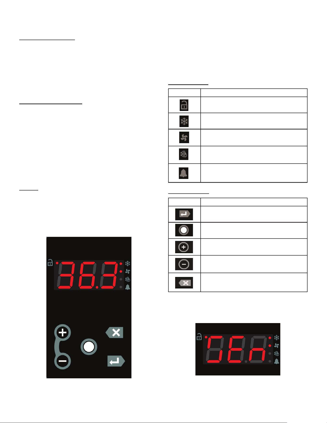
Display
Your new Traulsen refrigerator, freezer or hot food cabinet
is equipped with a multi-patented Smart Control™, which
precisely regulates operation and provides critical alarms if
problems occur. It is supplied from the factory ready to use
and requires no adjustment (except hot food units which are
set in the "OFF" position).
gure 11
On the left side of the display, there are four icons that refrlect
the status of the compressor, fans, defrost and alarms.
At the center of the display is text that shows the cabinet
temperature (see gure 11). It will also be used to access
the control settings. Below the display are ve tactile buttons
used to access the control menu system.
Status Symbols
Button Symbols
NOTE: While accessing the control menu, text messages
will be displayed. For example, the text displayed in gure
12 below is denoted as follows "SEn" (submenu).
SYMBOL DESCRIPTION
Unlock
Compressor / Heater Status
Fan Status
Defrost Status
Alarm / Door Open
SYMBOL DESCRIPTION
Display / Enter
Unlock / Modify
Plus (+) / Next
Minus (-) / Previous
Escape / Back / Cancel
gure 12
-8-
Changing the Setpoint
The setpoint of the unit can be changed by following the
steps below:
1. Unlock the keypad by pressing the Unlock / Modify key
"○" twice in succession.
2. While the cabinet temperature is displayed (home screen),
press the Display / Enter Key "↵". "SEn" will display.
3. Push the Plus (+) or Minus (-) key to navigate the submenu
until "SEt" displays.
4. Push the Display / Enter "↵" key. "000" wil display.
5. Push the Display / Enter "↵" key two times to view the
setpoint.
6. Push and hold the Unlock / Modify key. The control will
now enter edit mode.
7. Push the Plus (+) or Minus (-) key to change the setpoint
to the desired temperature.
8. Push the Display / Enter "↵" key once to register the new
value.
9. Push the Display / Enter "↵" key again to confirm the
change. The new setpoint will now display.
10. Push the Escape /Back / Cancel key "X" twice to exit
the submenu system. The cabinet temperature will display.
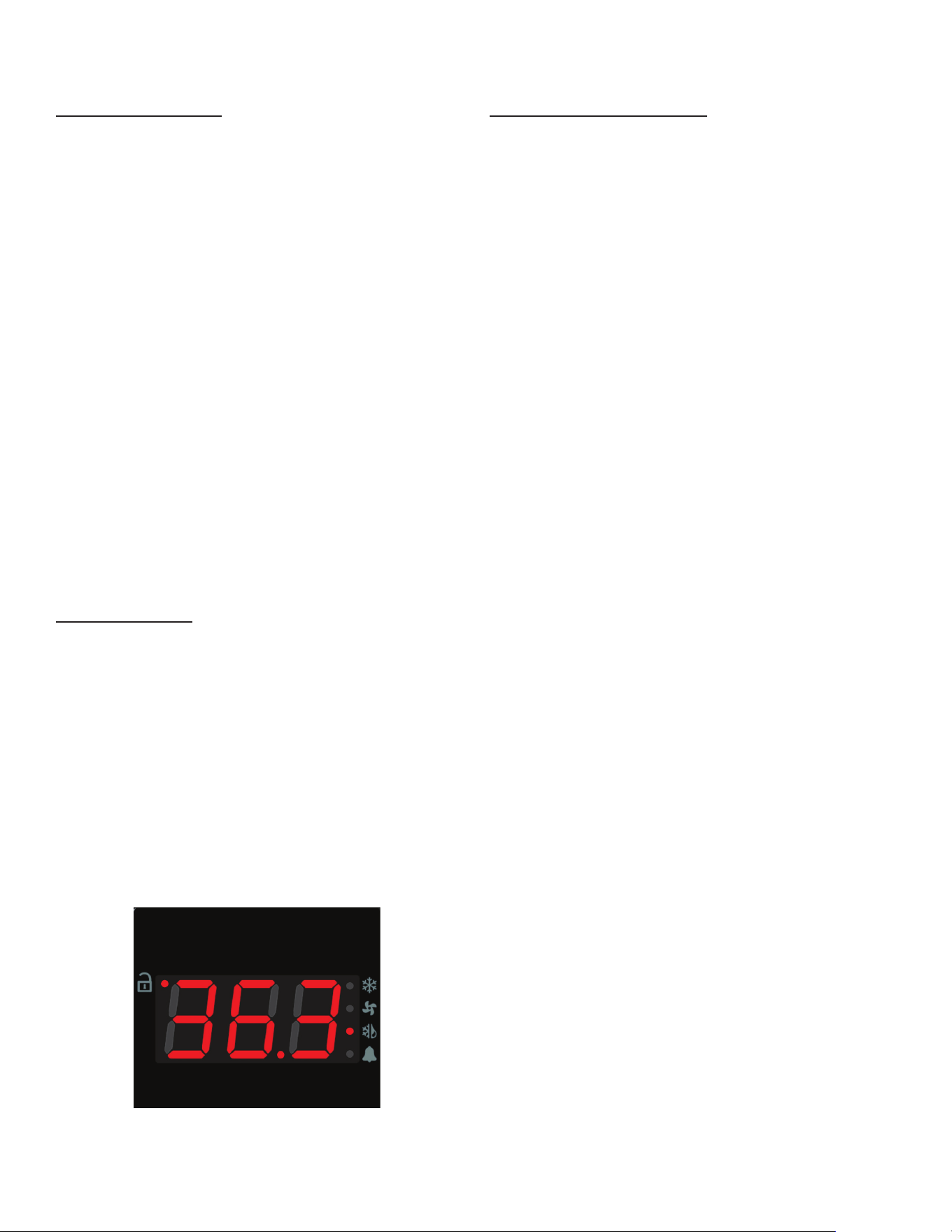
Initiating a Defrost
All Traulsen units are designed to defrost automatically. If
necessary, the user may manually initiate a defrost:
1. Unlock the keypad by pressing the Unlock / Modify key
"○" twice in succession.
2. While the cabinet temperature is displayed (home screen),
press the Display / Enter Key "↵". "SEn" will display.
3. Push the Plus (+) or Minus (-) key to navigate the submenu
system until "SdF" displays.
4. Push the Display / Enter Key "↵" twice to start a defrost.
Display will return to the home screen and the defrost icon
should light up (see figure 13). The unit will terminate the
defrost automatically without user intervention.
Changing the Defrost Interval
1. Unlock the keypad by pressing the Unlock / Modify key
"○" twice in succession.
2. While the cabinet temperature is displayed (home screen),
press the Display / Enter Key "↵". "SEn" will display.
3. Push the Plus (+) or Minus (-) key to navigate the submenu
system until "SEt" displays.
4. Push the Display / Enter "↵" key. "000" wil display.
5. Push the Plus (+) or Minus (-) key to set the first number
to 5, then push the Display / Enter "↵" key.
6. Push the Plus (+) or Minus (-) key to set the second number
to 5, then push the Display / Enter "↵" key.
7. Push the Plus (+) or Minus (-) key to set the third number
to 5, then push the Display / Enter "↵" key. (The password
is 555).
8. Push the Display / Enter Key "↵" again to enter the settings
submenu. "SP" will display.
9. Push the Plus (+) or Minus (-) key to navigate the settings
submenu until "di" displays.
10. Push the Unlock / Modify key "○". The control will now
enter edit mode. The "hh" hour digits will start blinking.
11. Push the Plus (+) or Minus (-) key to adjust the "hh" digit
and push the Display / Enter Key "↵" once to register the
new value.
12. The "mm" (minute) digits will now start blinking. Push the
Plus (+) or Minus (-) key to adjust the "mm" digit and push
the Display / Enter Key "↵" once to register the new value.
13. The "ss" (seconds) digits will now start blinking. Push
the Plus (+) or Minus (-) key to adjust the "ss" digit and push
the Display / Enter Key "↵" once to register the new value.
14. Push the Display / Enter Key "↵" again to confirm the
change. The new setting will now display.
15. Push the Escape /Back / Cancel key "X" twice to exit the
submenu system.
gure 13

-9-
Accessing the Power Failure Data
1. Unlock the keypad by pressing the Unlock / Modify key
"○" twice in succession.
2. While the cabinet temperature is displayed (home screen),
press the Display / Enter Key "↵". "SEn" will display.
3. Push the Plus (+) or Minus (-) key to navigate the submenu
system until "Al" displays.
4. Push the Display / Enter Key "↵"to navigate the alarm
menu board.
5. Push the Plus (+) or Minus (-) key to navigate to parameter
"tPd". The user will see the time duration the unit was powered
down by pressing and holding the Display / Enter Key "↵".
6. Push the Plus (+) or Minus (-) keyto navigate to parameter
"tCu". The user will view the temperature recorded at the
moment power was restored to the unit. This will be the
warmest temperature during a power loss event.
7. To clear the alarm, push the Display / Enter Key "↵" again
and use the Plus (+) or Minus (-) keyto navigate to parameter
"PFA". The parameter will display "Al". Push the Display /
Enter Key "↵" twice to clear the alarm so that parameter
displays "nor".
8. Push the Escape /Back / Cancel key "X" twice to exit the
submenu system.
NOTE: You can use the Plus (+) or Minus (-) key in a similar
fashion to review the status of other alarms while on step
5. For a list of alarms and other parameters please see the
"Parameter Quick Reference Chart" in the following sections.
Turning the Unit ON/OFF (Hot Food Units Only)
To turn OFF the hot food unit, press the Escape /Back /
Cancel key "X"until nothing is displayed on the screen. Push
any key to turn the unit back ON.
Changing Fahrenheit to Celsius
1. Unlock the keypad by pressing the Unlock / Modify key
"○" twice in succession.
2. While the cabinet temperature is displayed (home screen),
press the Display / Enter Key "↵". "SEn" will display.
3. Push the Plus (+) or Minus (-) key to navigate the submenu
system until "SEt" displays.
4. Push the Display / Enter "↵" key. "000" wil display.
5. Push the Plus (+) or Minus (-) key to set the first number
to 5, then push the Display / Enter "↵" key.
6. Push the Plus (+) or Minus (-) key to set the second number
to 5, then push the Display / Enter "↵" key.
7. Push the Plus (+) or Minus (-) key to set the third number
to 5, then push the Display / Enter "↵" key. (The password
is 555).
8. Push the Display / Enter Key "↵" again to enter the settings
submenu. "SP" will display.
9. Push the Plus (+) or Minus (-) key to navigate the settings
submenu until "tun" displays.
10. Push the Unlock / Modify key "○". The control will now
enter edit mode.
11. Push the Plus (+) or Minus (-) key to select "F" for
Fahrenheit or "C" for Celsius and push the Display / Enter
Key "↵" once to register the new value.
12. Push the Display / Enter Key "↵"again to confirm the
change.
13. Push the Escape /Back / Cancel key "X" twice to exit the
submenu system.
-10-
Parameter Quick Reference Chart
PARAMETER SUBMENU PASSWORD DATA
COMMONLY REFERENCED
SP
Sensor Readings N/A Cabinet Temperature
tE
Sensor Readings N/A Evaporator Coil Temperature
tLi
Sensor Readings N/A Liquid Line Temperature
SP
Settings 555 Temperature Setpoint
SPd
Settings 555 Cabinet Temperature Dierential
Fno
Settings 555 Fan Mode
dSP
Settings 555 Defrost Setpoint
dFo
Settings 555 Defrost Mode
di
Settings 555 Interval Between Defrosts
SEr
Settings 555 EOL: Serial Number
ALARMS
tCu
Alarms N/A Cabinet Temperature at Power Return
tPd
Alarms N/A Time of Power Failure
tPu
Alarms N/A Time of Power Return
PFd
Alarms N/A Duration of Power Failure
PFA
Alarms N/A
Power Failure Alarm Status
- "Alarm" = Power Failure
- "Normal" = Alarm Has Been Cleared
tCA
Alarms N/A Cabinet Temperature Alarm Status
VII. Troubleshooting Guide
-11-
PROBLEM REMEDY
1. Condensing unit fails to start.
a. Has the cord and plug has been disconnected?
Reconnect.
b. Check control temperature setting.
2. Condensing unit operates for prolonged periods or
continuously.
a. Are doors open? Shut completely.
b. Is the condenser coil clean? Clean properly.
c. Is the evaporator coil frozen? Initiate defrost.
3. Food compartment is too warm.
a. Check doors and gaskets for proper alignment and seal.
b. Has a large quantity of warm food recently been added,
or was the door kept open for a long period of time? In
both cases allow adequate time for the cabinet to recover
its normal operating temperature.
c. Is the setpoint too high? Readjust setpoint.
d. Is the condenser coil clean? Clean properly.
e. Is product properly loaded into the unit? Be sure to allow
proper airow.
4. Food compartment is too cold.
a. Has a large quantity of very cold or frozen food recently
been added? Allow adequate time for the cabinet to
recover its normal operating temperature.
b. Is the setpoint too low? Readjust the setpoint.
5. Condensation on the exterior surface.
a. Check doors and gaskets for proper alignment and seal.
b. Depending on amount, condensation could be normal if
unit is in a high-humidity environment.
6. Compressor hums but does not start. a. Call for service.
7. Door open icon continually illuminated.
a. Are doors open? Shut completely.
b. The door switch could be faulty. Replace the door
switch.
8. Door open icon does not illuminate. a. The door switch is faulty. Replace the door switch.
9. Evaporator fans not operating.
a. A defrost cycle is in progress (freezers only).
b. If defrost is not in progress, call for service.
10. No power to unit.
a. Has the cord and plug has been disconnected?
Reconnect.
b. If cord and plug is connected, check power supply
breaker.
-12-
VIII. Service & Warranty
Information
Before calling for service, please check the following:
Is the electrical cord plugged in? NOTE: If the SUPPLY CORD is damaged, it must be replaced by the manufacturer,
its service agent, or similarly qualied persons in order to avoid a possible electrical hazard.
Is the fuse OK or circuit breaker on?
Is the condenser coil clean?
Is the power switch on?
If after checking the above items and the unit is still not operating properly, please contact an authorized Traulsen service agent:
4401 Blue Mound Road Fort Worth, TX 76106 | (800) 825-8220. Traulsen reserves the right to change specications or
discontinue models without notice.
NOTE: The ISO 7010-W021 symbol is a standardized safety sign used internationally to indicate a potential re hazard.
It features a black ame icon on a triangular yellow background with a black border, following ISO guidelines for warning
symbols. This appliance is marked with the ISO 7010-W021 warning label to indicate the presence of FLAMMABLE
REFRIGERANTS. Prior to beginning work on systems containing FLAMMABLE REFRIGERANTS, safety checks are
necessary to ensure that the risk of ignition is minimized.
Ventilated Area
Ensure that the area is in the open or that it is adequately ventilated before breaking into the system or conducting any
hot work. A degree of ventilation shall continue during the period that the work is carried out. The ventilation should safely
disperse any released refrigerant and preferably expel it externally into the atmosphere.
Cabling
Check that cabling will not be subject to wear, corrosion, excessive pressure, vibration, sharp edges, or any other adverse
environmental eects. The check shall also take into account the eects of aging or continual vibration from sources such
as compressors or fans.
Detection of Flammable Refrigerants
Under no circumstances shall potential sources of ignition be used in the searching for or detection of refrigerant leaks. A
halide torch (or any other detector using a naked ame) shall not be used.
The following leak detection methods are deemed acceptable for all refrigerant systems. Electronic leak detectors may
be used to detect refrigerant leaks but, in the case of FLAMMABLE REFRIGERANTS, the sensitivity might not be
adequate, or might need recalibration. (Detection equipment shall be calibrated in a refrigerant-free area.) Ensure that
the detector is not a potential source of ignition and is suitable for the refrigerant used. Leak detection equipment shall be
set at a percentage of the LFL of the refrigerant and shall be calibrated to the refrigerant employed, and the appropriate
percentage of gas (25 % maximum) is conrmed.
Leak detection uids are also suitable for use with most refrigerants but the use of detergents containing chlorine shall be
avoided as the chlorine can react with the refrigerant and corrode the copper pipe-work.
NOTE: Examples of leak detection uids are
• bubble method
• uorescent method agents
If a leak is suspected, all naked ames shall be removed/extinguished.
If a leakage of refrigerant is found which requires brazing, all of the refrigerant shall be recovered from the system, or iso-
lated (by means of shut o valves) in a part of the system remote from the leak. Removal of refrigerant shall be according
to the removal & evacuation section below.
Removal & Evacuation
When breaking into the refrigerant circuit to make repairs- or for any other purpose - conventional procedures shall
be used. However, for ammable refrigerants it is important that best practice be followed, since ammability is a
consideration. The following procedure shall be adhered to:
a) safely remove refrigerant following local and national regulations;
b) purge the circuit with inert gas;
c) evacuate
d) purge with inert gas;
e) open the circuit by cutting or brazing.
The refrigerant charge shall be recovered into the correct recovery cylinders if venting is not allowed by local and national
codes. For appliances containing ammable refrigerants, the system shall be purged with oxygen- free nitrogen to render
the appliance safe for ammable refrigerants. This process might need to be repeated
several times. Compressed air or oxygen shall not be used for purging refrigerant systems .
For appliances containing ammable refrigerants, refrigerants purging shall be achieved by breaking the vacuum in the
system with oxygen-free nitrogen and continuing to ll until the working pressure is achieved, then venting to atmosphere,
and nally pulling down to a vacuum. This process shall be repeated until no refrigerant is within the system (optional for
A2L). When the nal oxygen-free nitrogen charge is used, the system shall be vented down to atmospheric pressure to
enable work to take place.
Ensure that the outlet for the vacuum pump is not close to any potential ignition sources and that ventilation is available.
Spare Parts Information
To purchase replacement parts or to speak to service support for Traulsen units please contact our Ft. Worth facility by phone
at 800-825-8220 or fax to 817-740-6748 (parts) or 817-740-6757 (service).
NOTE: When calling for spare parts or service support, please make sure you have model and serial number of unit available.
Model Number
Serial Number
ITW Food Equipment Group, LLC
North American Refrigeration
4401 Blue Mound Rd.
Ft. Worth, TX 76106
800-825-8220
MODEL:
MODELO:
MODELE:
RDT232WUT-FHS
SERIAL NUMBER:
25F02060
SCAN FOR SERVICE INFO
REFRIGERANT / REFRIGERANTE / RÉFRIGÉRANT
SYS1 (REFM):
R-290
3.80 OZ
107.71 g
107,71 g
Hi Press. (PRESH):
360.00 psi
2,482.11 kPa
2.482,11 kPa
Lo Press. (PRESL):
130.00 psi
896.32 kPa
896,32 kPa
SYS2 (REFA):
R-290
3.00 OZ
85.04 g
85,04 g
Hi Press. (PRESH):
460.00 psi
3,171.59 kPa
3.171,59 kPa
Lo Press. (PRESL):
140.00 psi
965.27 kPa
965,27 kPa
Input Power (ELIN) - FOR INDOOR USE ONLY
Voltage
Hertz
Phase
Total Amps
115 ~
60
1
12.60
Device/Part Number:
RD232W-291
Device/Part Notes:
COMPONENTS / COMPOSANTS / COMPONENTES
1
2
MAX OVER CURRENT PROTECTION (A):
COMP AMPS:
MIN CIRCUIT IN AMPS:
COND FAN AMPS:
DOME LIGHT WATTS:
11
EVAP FAN AMPS:
DISPLAY LIGHT WATTS:
CONTROL AMPS:
DOOR HEATER WATTS:
DEF HEATER WATTS:
B/TMCE HTR WATTS:
370-60297-00 REV. D 01/15/2024
-13-

Warranty Registration
The warranties for your new Traulsen unit may be registered with us by completing warranty information online, via our
website www.Traulsen.com. Click on the Warranty Registration text of the Service tab at the top of the home page. You
may also register your product by calling us directly at 800-825-8220.
-14-

4401 Blue Mound Road Fort Worth, Texas 76106 (USA)
Phone: 800.825.8220 | Service Fax: 817.740.6757 | E-mail: [email protected] | Website: traulsen.com
Form Number: TR35743 | Part Number: 375-60311-00 | Revision Date: 04/2026
Traulsen © All Rights Reserved