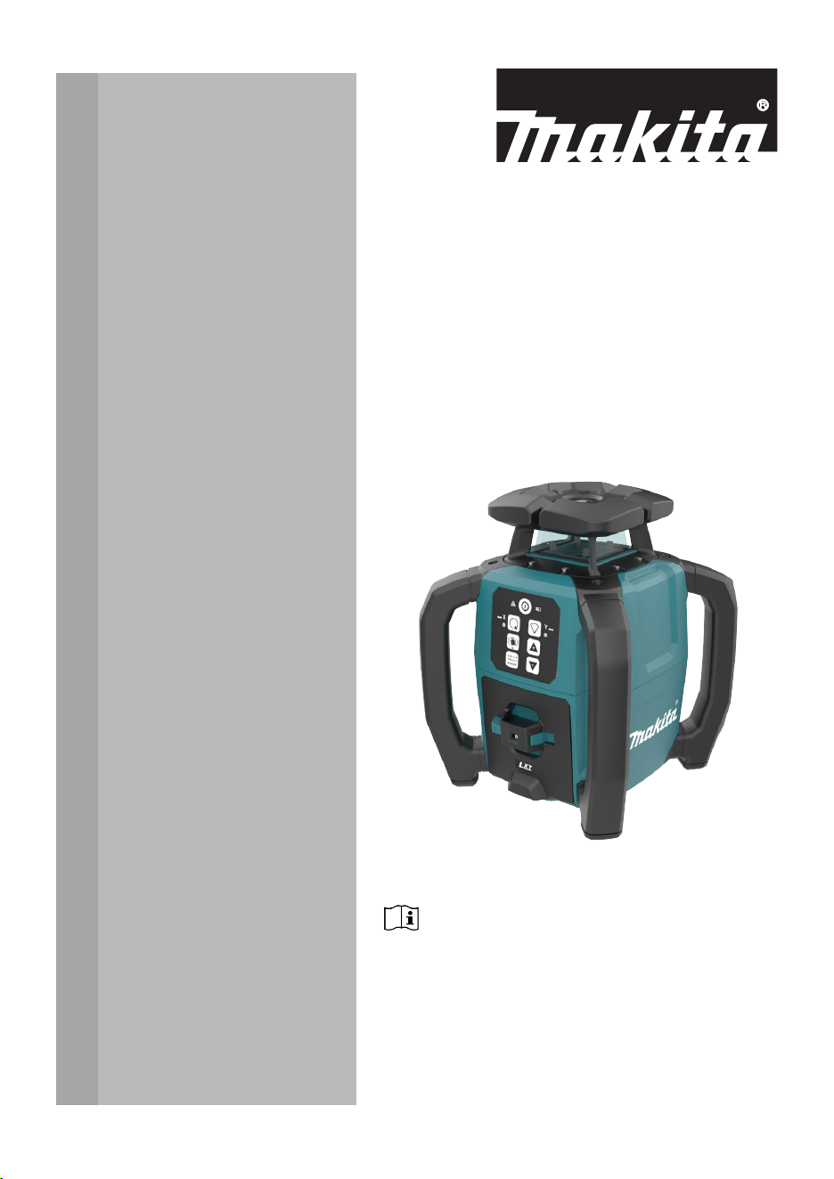
SKR001
INSTRUCTION MANUAL
ENGLISH (Original instructions)
Read before use.
Introduction
Congratulations on the purchase of a Makita Rotating Laser product.
This manual contains important safety directions as well as instructions for
setting up the product and operating it. Refer to 1 Safety Directions for
further information.
Read carefully through the User Manual before you switch on the product.
The model and serial number of your product are indicated on the type label.
Always refer to this information when contacting your agency or Makita
authorised service centre.
Name Description/Format
SKR001
Quickstart
Guide
Provides an overview of the
product. Intended as a quick refer-
ence guide.
ü ü
SKR001
Instruction
Manual
All instructions required in order
to operate the product to a basic
level are contained in the Instruc-
tion Manual. Provides an overview
of the product together with tech-
nical data and safety directions.
–
ü
Purchase
Product
identication
Available
documentation
2

Table of Contents
1 Safety Directions 5
1.1 General 5
1.2 Denition of Use 6
1.3 Limits of Use 6
1.4 Responsibilities 6
1.5 Hazards of Use 7
1.6 Laser Classication 13
1.6.1 General 13
1.6.2 SKR001 13
1.7 Electromagnetic Compatibility (EMC) 14
2 Description of the System 16
2.1 System Components 16
2.2 SKR001 Laser Components 17
2.3 Case Components 17
2.4 Setup 18
3 Operation 19
3.1 Buttons 19
3.2 LED Indicators 20
3.3 Turning the SKR001 On and Off 21
3.4 Automatic Mode 22
3.5 Manual Mode 22
3.6 Horizontal Use 25
3.7 Layout/Laydown Use 25
3.8 Height of Instrument Alert (H.I.Alert) function 25
3.9 RC1 Remote Control 28
3.9.1 Pairing the SKR001 with the RC1 Remote Control 29
4 LDX2 Digital Receiver 31
5 Applications 37
5.1 Setting Forms 37
5.2 Checking Grades 38
5.3 Manual Grades 39
5.4 Suspended Ceilings 40
5.5 Layout/Laydown Mode 41
5.6 More Applications 42
6 Batteries 43
6.1 Operating Principles 43
6.2 Battery for SKR001 43
7 Accuracy Adjustment 46
7.1 Checking the Level Accuracy 46
7.2 Adjusting the Self-Levelling Accuracy 47
7.2.1 Horizontal Position 47
7.2.2 Laydown Position 51
8 Troubleshooting 54
Table of Contents 3

9 Care and Transport 57
9.1 Transport 57
9.2 Storage 57
9.3 Cleaning and Drying 58
10 Technical Data 59
10.1 Conformity to National Regulations 59
10.1.1 SKR001 59
10.1.2 RC1 Remote Control 61
10.1.3 LDX2 Digital Receiver 61
10.2 General Technical Data of the Product 62
10.2.1 SKR001 62
10.2.2 RC1 Remote Control 63
10.2.3 LDX2 Digital Receiver 64
10.3 Dangerous Goods Regulations 65
11 Accessories 66
4 Table of Contents
1 Safety Directions
1.1 General
The following directions enable the person responsible for the product, and
the person who actually uses the equipment, to anticipate and avoid opera-
tional hazards.
The person responsible for the product must ensure that all users under-
stand these directions and adhere to them.
Warning messages are an essential part of the safety concept of the instru-
ment. They appear wherever hazards or hazardous situations can occur.
Warning messages...
•
make the user alert about direct and indirect hazards concerning the
use of the product.
•
contain general rules of behaviour.
For the users‘ safety, all safety instructions and safety messages shall be
strictly observed and followed! Therefore, the manual must always be avail-
able to all persons performing any tasks described here.
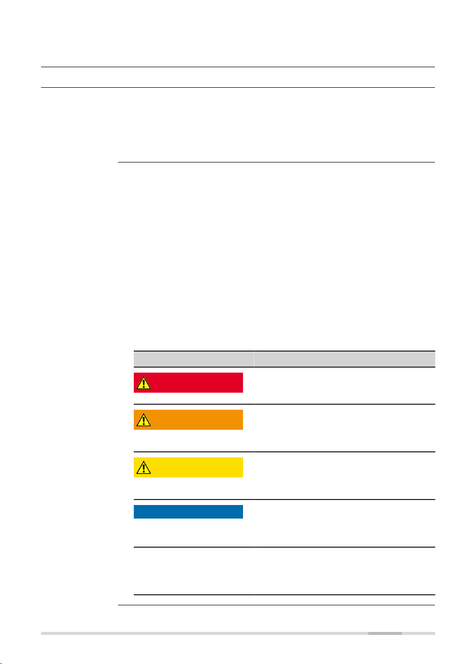
DANGER, WARNING, CAUTION and NOTICE are standardised signal words
for identifying levels of hazards and risks related to personal injury and
property damage. For your safety, it is important to read and fully under-
stand the following table with the different signal words and their deni-
tions! Supplementary safety information symbols may be placed within a
warning message as well as supplementary text.
Type Description
DANGER
Indicates an imminently hazardous situ-
ation which, if not avoided, will result in
death or serious injury.
WARNING
Indicates a potentially hazardous situation
or an unintended use which, if not
avoided, could result in death or serious
injury.
CAUTION
Indicates a potentially hazardous situation
or an unintended use which, if not
avoided, may result in minor or moderate
injury.
NOTICE
Indicates a potentially hazardous situation
or an unintended use which, if not
avoided, may result in appreciable material,
nancial and environmental damage.
☞
Important paragraphs which must be
adhered to in practice as they enable the
product to be used in a technically correct
and efcient manner.
Description
About warning
messages
Safety Directions 5

1.2 Denition of Use
•
Projection of horizontal and vertical laser lines and laser points
•
The laser beam can be detected by means of a laser receiver
•
Remote control of product
•
Use of the product without instructions
•
Use outside of the intended use and limits
•
Disabling of safety systems
•
Removal of hazard notices
•
Opening the product using tools, for example a screwdriver, unless this
is permitted for certain functions
•
Modication or conversion of the product
•
Use after misappropriation
•
Use of products with recognisable damage or defects
•
Use with accessories from other manufacturers without the prior writ-
ten explicit approval of Makita
•
Inadequate safeguards at the working site
•
Deliberate dazzling of third parties
•
Controlling of machines, moving objects or similar monitoring applica-
tions without additional control and safety installations
1.3 Limits of Use
Suitable for use in an atmosphere appropriate for permanent human habita-
tion. Not suitable for use in aggressive or explosive environments.
WARNING
Working in hazardous areas or close to electrical installations or sim-
ilar situations
Life Risk.
Precautions:
▶
Local safety authorities and safety experts must be contacted by the
person responsible for the product before working in such conditions.
1.4 Responsibilities
Makita Corporation Anjo, 3‑11‑8, Sumiyoshi‑cho, Aichi 446‑8502, Japan
Makita, Jan‑Baptist Vinkstraat 2, 3070 Belgium
www.makita.com
The company above is responsible for supplying the product, including the
Instruction Manual in a completely safe condition.
The company above is not responsible for third-party accessories.
Intended use
Reasonably
foreseeable
misuse
Environment
Manufacturer of
the product
6 Safety Directions
The person responsible for the product has the following duties:
•
To understand the safety instructions on the product and the instruc-
tions in the User Manual
•
To ensure that the product is used in accordance with the instructions
•
To be familiar with local regulations relating to safety and accident
prevention
•
To stop operating the system and inform Makita immediately if the
product and the application become unsafe
•
To ensure that the national laws, regulations and conditions for the
operation of the product are respected
•
Always prevent access to the product by unauthorised personnel
☞
The product is permitted to use for skilled persons only.
1.5 Hazards of Use
NOTICE
Dropping, misusing, modifying, storing the product for long periods or
transporting the product
Watch out for erroneous measurement results.
Precautions:
▶
Periodically carry out test measurements and perform the eld adjust-
ments indicated in the User Manual, particularly after the product has
been subjected to abnormal use as well as before and after important
measurements.
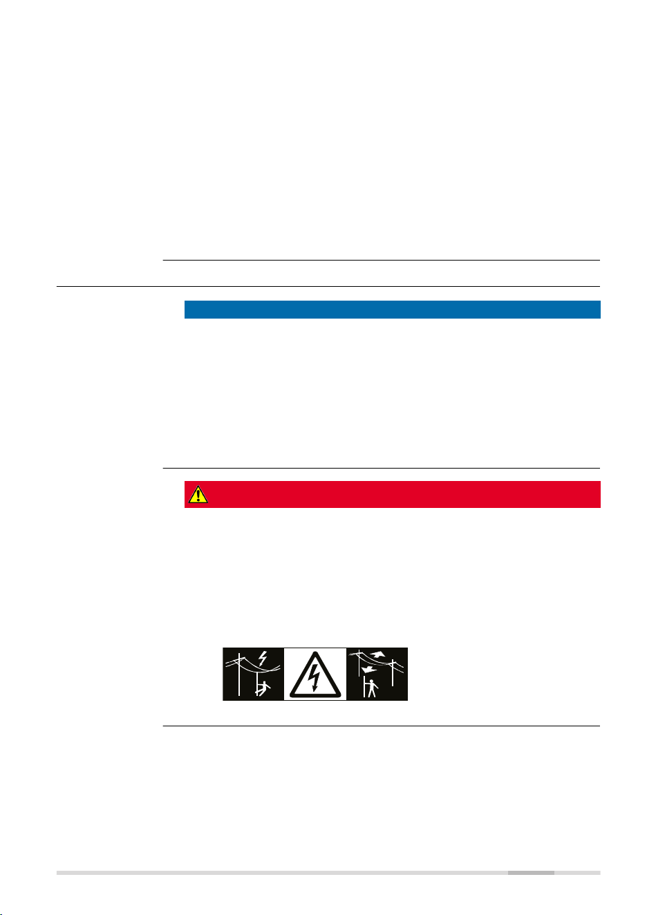
DANGER
Risk of electrocution
Because of the risk of electrocution, it is dangerous to use poles, levelling
staffs and extensions in the vicinity of electrical installations such as power
cables or electrical railways.
Precautions:
▶
Keep at a safe distance from electrical installations. If it is essential to
work in this environment, rst contact the safety authorities respons-
ible for the electrical installations and follow their instructions.
Person responsible
for the product
Safety Directions 7
WARNING
Lightning strike
If the product is used with accessories, for example masts, staffs, poles, you
may increase the risk of being struck by lightning.
Precautions:
▶
Do not use the product in a thunderstorm.
WARNING
Inadequate securing of the working site
This can lead to dangerous situations, for example in trafc, on building sites
and at industrial installations.
Precautions:
▶
Always ensure that the working site is adequately secured.
▶
Adhere to the regulations governing safety, accident prevention and
road trafc.
CAUTION
Not properly secured accessories
If the accessories used with the product are not properly secured and the
product is subjected to mechanical shock, for example blows or falling, the
product may be damaged or people can sustain injury.
Precautions:
▶
When setting up the product, make sure that the accessories are cor-
rectly adapted, tted, secured, and locked in position.
▶
Avoid subjecting the product to mechanical stress.
WARNING
Inappropriate mechanical inuences to batteries
During the transport, shipping or disposal of batteries it is possible for inap-
propriate mechanical inuences to constitute a re hazard.
Precautions:
▶
Before shipping the product or disposing it, discharge the batteries by
the product until they are at.
▶
When transporting or shipping batteries, the person in charge of the
product must ensure that the applicable national and international
rules and regulations are observed.
▶
Before transportation or shipping, contact your local passenger or
freight transport company.
8 Safety Directions
WARNING
Distraction/loss of attention
During dynamic applications, for example stakeout procedures, there is a
danger of accidents occurring if the user does not pay attention to the
environmental conditions around, for example obstacles, excavations or
trafc.
Precautions:
▶
The person responsible for the product must make all users fully aware
of the existing dangers.
WARNING
Unauthorised opening of the product
Either of the following actions may cause you to receive an electric shock:
•
Touching live components
•
Using the product after incorrect attempts were made to carry out
repairs
Precautions:
▶
Do not open the product!
▶
Only authorised Makita Service Centres are entitled to repair these
products.
WARNING
Improper disposal
If the product is improperly disposed of, the following can happen:
•
If polymer parts are burnt, poisonous gases are produced which may
impair health.
•
If batteries are damaged or are heated strongly, they can explode and
cause poisoning, burning, corrosion or environmental contamination.
•
By disposing of the product irresponsibly you may enable unauthorised
persons to use it in contravention of the regulations, exposing them-
selves and third parties to the risk of severe injury and rendering the
environment liable to contamination.
Precautions:
▶
The product must not be disposed with household
waste.
Dispose of the product appropriately in accordance
with the national regulations in force in your country.
Always prevent access to the product by unauthorised
personnel.
Product-specic treatment and waste management information can be
received from your Makita distributor.
Safety Directions 9

WARNING
Improperly repaired equipment
Risk of injuries to users and equipment destruction due to lack of repair
knowledge.
Precautions:
▶
Only authorised Makita Service Centres are entitled to repair these
products.
WARNING
Exposure of batteries to high mechanical stress, high ambient temper-
atures or immersion into uids
This can cause leakage, re or explosion of the batteries.
Precautions:
▶
Protect the batteries from mechanical inuences and high ambient
temperatures. Do not drop or immerse batteries into uids.
WARNING
Short circuit of battery terminals
If battery terminals are short circuited e.g. by coming in contact with jew-
ellery, keys, metallised paper or other metals, the battery can overheat and
cause injury or re, for example by storing or transporting in pockets.
Precautions:
▶
Make sure that the battery terminals do not come into contact with
metallic/conductive objects.
WARNING
Electric shock due to use under wet and severe conditions
If unit becomes wet, it may cause you to receive an electric shock.
Precautions:
▶
If the product becomes humid, it must not be used!
▶
Use the product only in dry environments, for example in buildings or
vehicles.
▶
Protect the product against humidity.
10 Safety Directions
WARNING
Unauthorised opening of the product
Either of the following actions may cause you to receive an electric shock:
•
Touching live components
•
Using the product after incorrect attempts were made to carry out
repairs.
Precautions:
▶
Do not open the product!
▶
Only authorised Makita Service Centres are entitled to repair these
products.
WARNING
Short circuit of battery terminals
Risk of re, electric shock and damage.
Precautions:
▶
Do not open the battery housing.
▶
Keep away any metallic or wet objects from the battery terminals.
WARNING
Magnetic eld
Magnets integrated in the target plate may affect the function of the pace-
maker.
Precautions:
▶
Do not use the target plate near a pacemaker.
WARNING
Battery pack of the signal transmitter may get hot after prolonged
use
Risk of burning injuries.
Precautions:
▶
Avoid touching the hot battery pack.
▶
Allow the battery pack to cool down before removing it.
Safety Directions 11
WARNING
Working with laser devices
If the necessary measures for laser safety are not adopted, working with
laser devices can be hazardous.
Precautions:
▶
Observe the User Manual of the respective laser device.
▶
Only use and operate the laser device as dened in the laser safety
directions.
CAUTION
Laser beam
Rotating lasers are safe for momentary exposures but can be hazardous for
deliberate staring into the beam. The beam may cause dazzle, ash-blind-
ness and after-images, particularly under low ambient light conditions.
The goggles do not protect your eyes against the laser beam. They are only
used to increase the visibility of the laser beam.
Precautions:
▶
Do not stare into the laser beam.
CAUTION
Battery tray not locked securely
If the battery tray is not locked securely, it may fall out of the SKR001
accidentally and might cause damage and injury.
Precautions:
▶
Install and lock the battery tray securely.
CAUTION
Signal sound > 80 db(A)
The A-weighted sound pressure level of the signal sound is > 80 db(A) at a
distance of one metre. Your hearing may be damaged.
Precautions:
▶
Do not hold the device or the laser receiver directly to your ear.
CAUTION
Rotating lasers are safe for momentary exposures but can be hazardous for
deliberate staring into the beam. The beam may cause dazzle, ash-blind-
ness and after-images, particularly under low ambient light conditions.
Precautions:
▶
Do not stare into the laser beam.
12 Safety Directions

NOTICE
Misalignment of laser plane
Any misalignment of the laser plane will impact the grade of the work being
done.
Precautions:
▶
Take care that the laser plane of the rotating laser is at the intended
height.
▶
Take special care to protect the laser from impacts or bumps and make
sure that the tripod is set on stable ground.
1.6 Laser Classication
1.6.1 General
The following chapters provide instructions and training information about
laser safety according to international standard IEC 60825-1 (2014-05) and
technical report IEC TR 60825-14:2022. The information enables the person
responsible for the product and the person who actually uses the equip-
ment, to anticipate and avoid operational hazards.
☞
According to IEC TR 60825-14:2022, products classied as laser
class 1, class 2 and class 3R do not require:
•
laser safety ofcer involvement
•
protective clothes and eyewear
•
special warning signs in the laser working area
if used and operated as dened in this User Manual due to the
low eye hazard level.
☞
National laws and local regulations could impose more strin-
gent instructions for the safe use of lasers than IEC 60825-1
(2014-05) and IEC TR 60825-14:2022.
1.6.2 SKR001
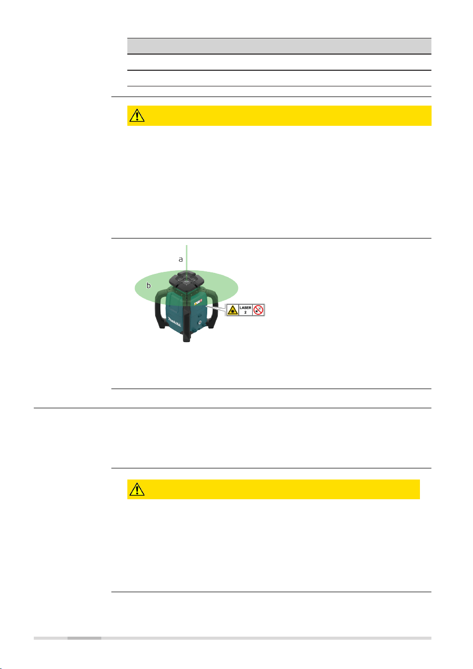
The rotating laser built into the product produces a visible laser beam which
emerges from the rotating head.
The laser product described in this section is classied as laser class 2 in
accordance with:
•
IEC 60825-1 (2014-05): “Safety of laser products”
These products are safe for momentary exposures but can be hazardous for
deliberate staring into the beam. The beam may cause dazzle, ash-blind-
ness and after-images, particularly under low ambient light conditions.
SKR001:
Description Value
Maximum average radiant output power < 1 mW
Pulse duration (effective) c.w./1.1 ms
Pulse repetition frequency c.w./10 Hz
General
General
Safety Directions 13
Description Value
Beam divergence < 1.5 mrad
Wavelength 520 nm
CAUTION
Class 2 laser product
From a safety perspective, class 2 laser products are not inherently safe for
the eyes.
Precautions:
▶
Avoid staring into the beam or viewing it through optical instruments.
▶
Avoid pointing the beam at other people or at animals.
▶
Avoid pointing the beam at aircraft or any other vehicles at any dis-
tances.
a Stationary laser beam
b Rotating laser beam
1.7 Electromagnetic Compatibility (EMC)
The term Electromagnetic Compatibility is taken to mean the capability of
the product to function smoothly in an environment where electromagnetic
radiation and electrostatic discharges are present, and without causing elec-
tromagnetic disturbances to other equipment.
CAUTION
Electromagnetic radiation
Electromagnetic radiation can cause disturbances in other equipment.
Precautions:
▶
Although the product meets the strict regulations and standards
which are in force in this respect, Makita cannot completely
exclude the possibility that other equipment may be disturbed.
Labelling
Description
14 Safety Directions
CAUTION
Intense electromagnetic radiation. For example, near radio transmit-
ters, transponders, two-way radios or diesel generators
Although the product meets the strict regulations and standards which are
in force in this respect, Makita cannot completely exclude the possibility that
the function of the product may be disturbed in such an electromagnetic
environment.
Precautions:
▶
Check the plausibility of results obtained under these conditions.
CAUTION
Exceeding the RF radiation exposure limits for general population
Health risk
Precautions:
▶
The antennas used for this transmitter must be installed such that a
minimum separation distance of at least 23 cm is always maintained
between the radiator (antenna) and all persons.
▶
The antennas used for this transmitter must not be co-located or
operated with any other antenna or transmitter.
WARNING
Use of product with radio or digital cellular phone devices
Electromagnetic elds can cause disturbances in other equipment, install-
ations, medical devices, for example pacemakers or hearing aids, and air-
crafts. Electromagnetic elds can also affect humans and animals.
Precautions:
▶
Although the product meets the strict regulations and standards which
are in force in this respect, Makita cannot completely exclude the
possibility that other equipment can be disturbed or that humans or
animals can be affected.
▶
Do not operate the product with radio or digital cellular phone devices
in the vicinity of lling stations or chemical installations, or in other
areas where an explosion hazard exists.
▶
Do not operate the product with radio or digital cellular phone devices
near medical equipment.
▶
Do not operate the product with radio or digital cellular phone devices
in aircrafts.
▶
Do not operate the product with radio or digital cellular phone devices
for long periods with the product immediately next to your body.
Safety Directions 15
2 Description of the System
2.1 System Components
The SKR001 is a laser tool for general construction and levelling applications
such as
•
Setting forms
•
Checking grades
•
Controlling depths for excavations
If set up within the self-levelling range, the SKR001 automatically levels
to create an accurate horizontal or vertical plane of laser light. Once the
SKR001 has levelled, the head will start rotating and the SKR001 is ready
for use. 30 seconds after the SKR001 has completed the levelling, the H.I.
Alert system becomes active and protects the SKR001 against changes in
elevation caused by movement of the tripod to ensure accurate work.
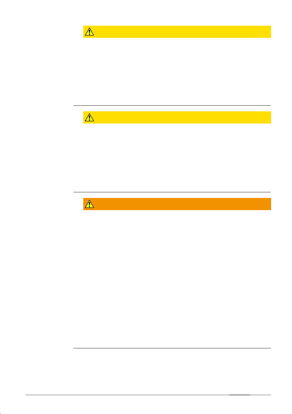
27421_001
a
b
d
e
f
c
a Digital receiver LDX2
b Remote control RC1
c Makita SKR001
d Battery tray: LXT
Optional: CXT/XGT
e Batteries: Optional
f Charger: Optional
The delivered components depend on the package ordered.
General descrip-
tion
Available system
components
☞
16 Description of the System
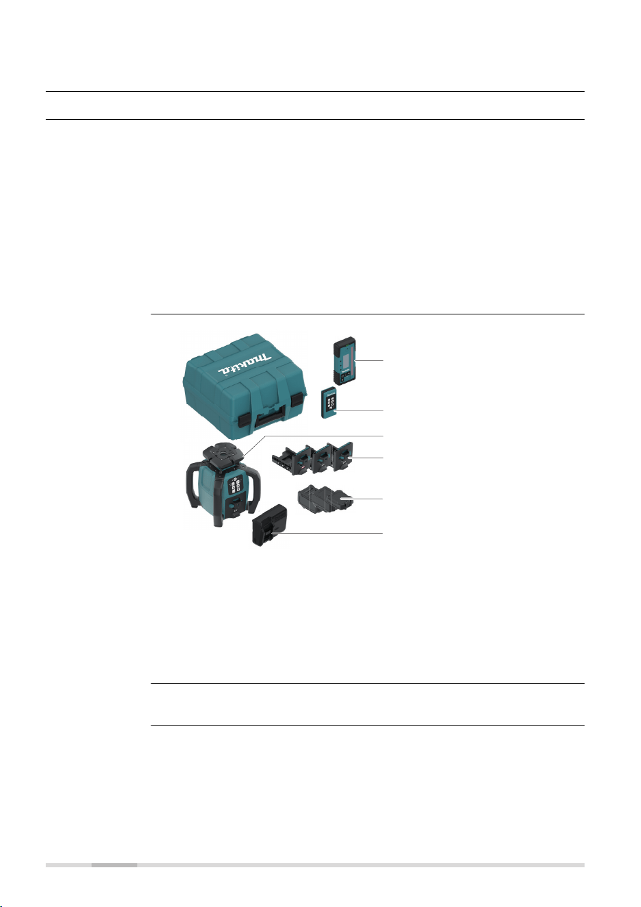
2.2 SKR001 Laser Components
a
b
c
d
27422_001
a Carry Handle
b LED Indicators
c Buttons
d Battery compartment
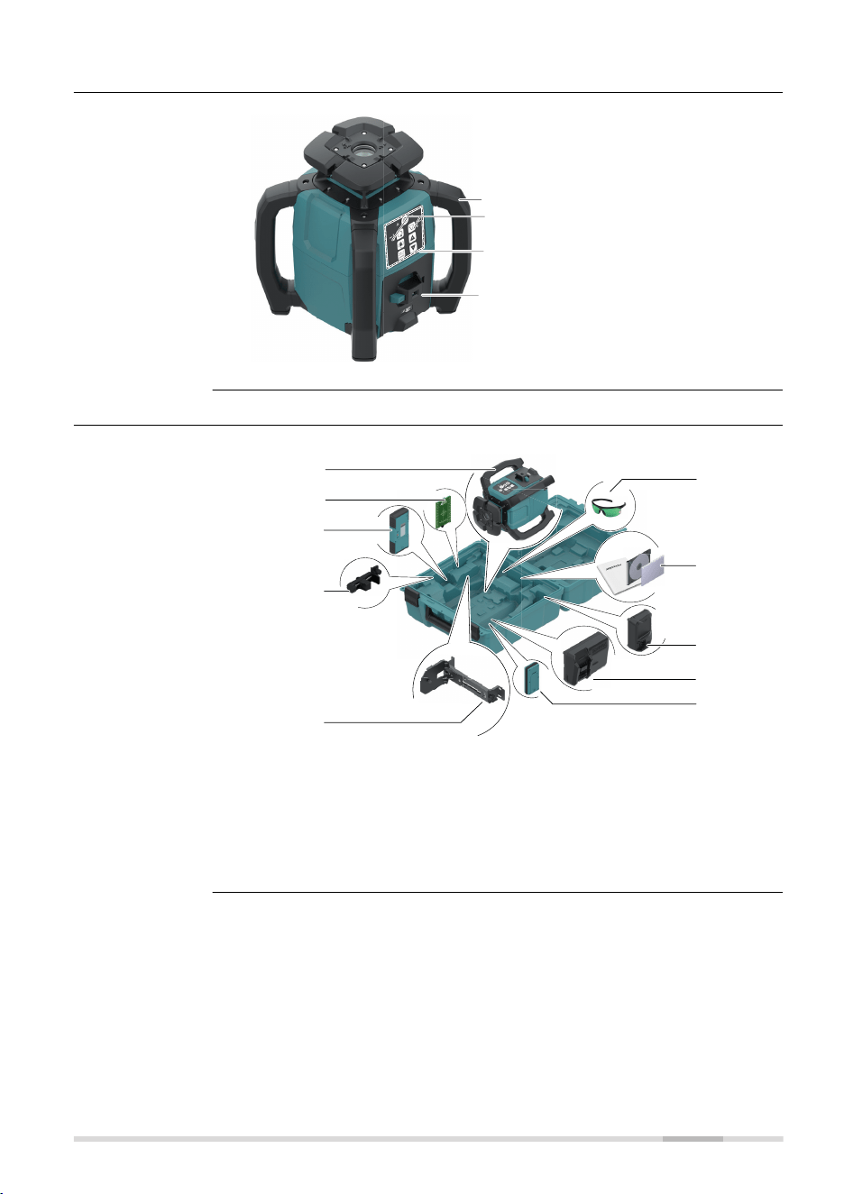
2.3 Case Components
Sa
f
e
t
y I
n
s
tr
u
c
t
i
o
n
s
27423_003
g
f
d
j
e
c
b
a
h
i
a Makita SKR001
b Target plate
c Digital receiver LDX2
d Bracket for Receiver
e Wall mount
f Laser visibility goggles
g Documentation
h Optional: Charger (LXT,
XGT)
i Optional: Charger (CXT)
j Remote control RC1
SKR001 laser com-
ponents
Case components -
interior
Description of the System 17
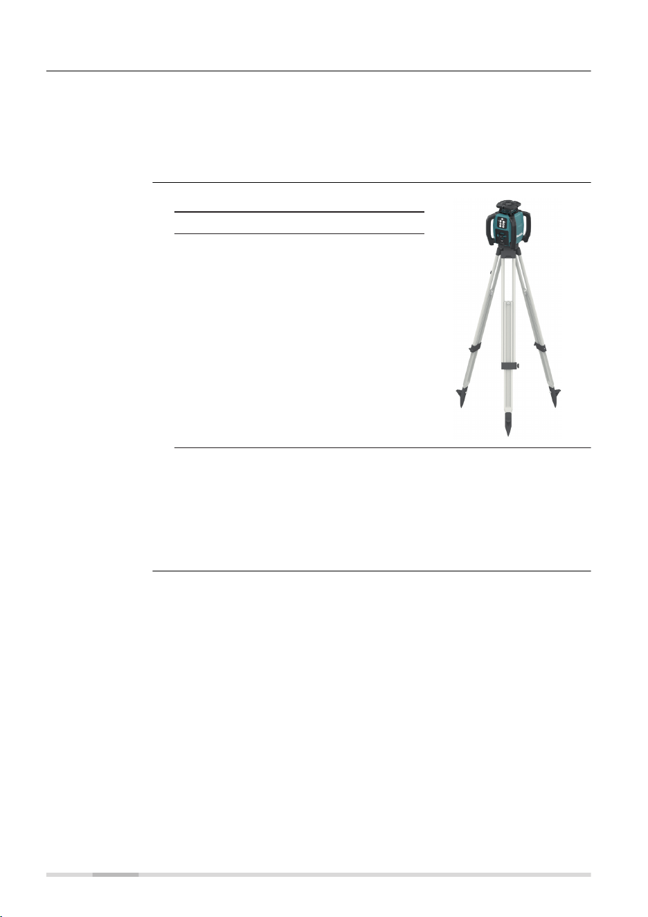
2.4 Setup
•
Keep the location clear of possible obstructions that could block or
reect the laser beam.
•
Place the SKR001 on stable ground. Ground vibration and extremely
windy conditions can affect the operation of the SKR001.
•
When working in a very dusty environment place the SKR001 up-wind
so the dirt is blown away from the laser.
1. Set up the tripod.
27424_001
2. Place the SKR001 on the tripod.
3. Tighten the screw on the underside
of the tripod to secure the SKR001
on the tripod.
☞
•
Attach the SKR001 securely to a tripod, or mount on a
stable level surface.
•
Always check the tripod before attaching the SKR001. Make
sure all screws, bolts and nuts are tight.
•
If a tripod has chains, they should be slightly loose to allow
for thermal expansion during the day.
•
Secure the tripod on extremely windy days.
Location
Setting up on a
Tripod
18 Description of the System
3 Operation
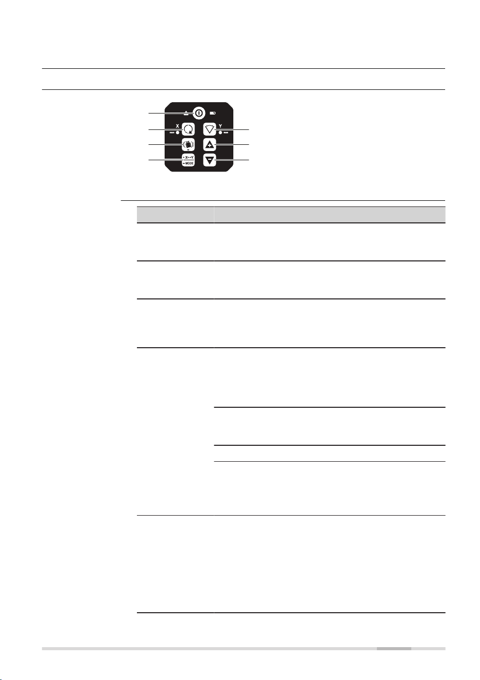
3.1 Buttons
27426_001
a
b
e
c
d
f
g
a Power
b Head speed
c H.I.Alert
d Automatic/Manual Mode,
select axis
e Scan mode
f Up
g Down
Button Function
Power Press to turn SKR001 on or off.
Both LED ash green until device is levelled - then
solid.
Head speed Press to change speed (in loop): Start is 600;
600/0/150/300/600 rpm
Refer to Change the rotation speed, in loop for details.
H.I.Alert Long press H.I.Alert button to activate/deactivate
H.I. Alert.
Refer to Description of the H.I.Alert function for
details.
Automatic/
Manual Mode,
select axis
Single axis slope mode:
Long press once to change the X‑axis to manual mode
with Y‑axis self-levelling.
Press again to change the Y‑axis to manual mode with
X‑axis self-levelling.
Dual axis slope mode:
Long press again to change both axes to manual mode
with no self-levelling.
Long press again to change back to automatic mode.
☞
Note the changes in the LED indicators in
the manual modes. The red LED indicates
that the corresponding axis is in manual
mode.
Scan mode Short press Scan button to activate scan mode.
Short press Scan button to change angle (in loop):
30°/20°/10°.
Refer to Change the scan angle, in loop for details.
☞
If scan mode is active, the X‑axis LED
and Y‑axis LED indicators ash alternately
orange and the previous colour (red or
green).
Buttons
Description of the
buttons
Operation 19
Button Function
Up/Down Rotates the scan area or tilt the axis/laser beam
depending on the operating mode.
☞
In Scan mode, it is not possible to tilt
axes.
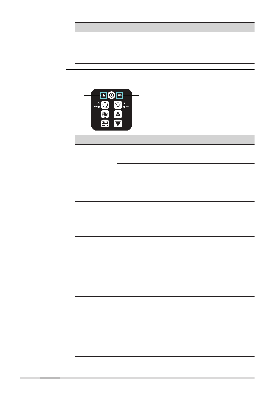
3.2 LED Indicators
27867_001
ab
a Alert LED:
H.I.Alert, servo, temperature
b Low Battery indicator LED
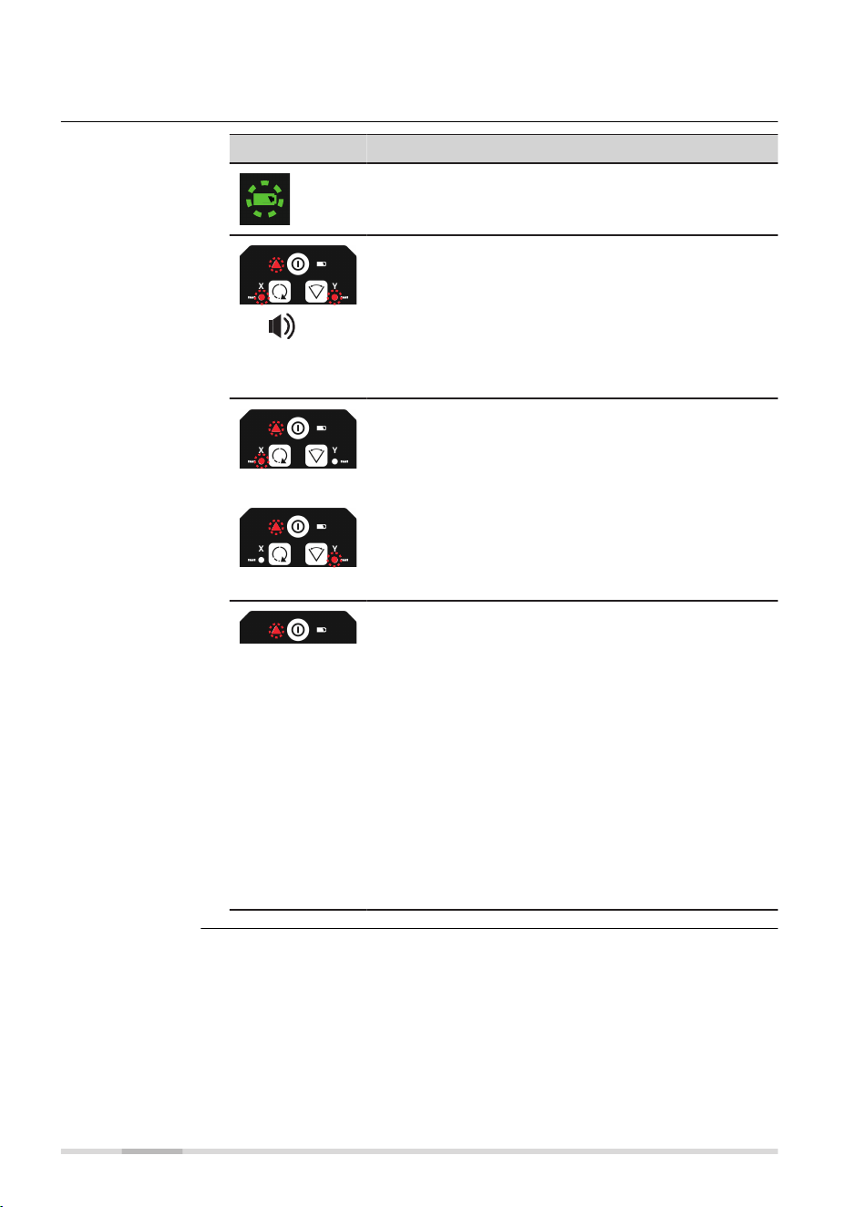
LED Status Mode/function
Alert LED Off H.I.Alert off.
Red: On H.I.Alert triggered.
Red: Slow ashing Initialisation ~30 s.
Red: Fast ashing,
2 Hz also X‑axis LED
and Y‑axis LED are
fast ashing
Alert indication.
Alert LED:
Servo limit
alert
Red: Fast ashing,
2 Hz and either X‑axis
LED or Y‑axis LED,
depending which axis
is at limit
No levelling.
Alert LED:
Environment
temperature
alert
Red: Fast ashing,
2 Hz
Alert is initiated, if:
• Temperature is ≥ 55 °C
• Temperature is ≤ −15 °C
After 2 minutes in the alert
condition, the unit shuts off
automatically.
☞
In case temperature reaches operating
temperature range again, the alert stops.
Indicator LED:
Low Battery
Green: On The battery is okay.
Green: Fast ashing,
2 Hz
Low-battery.
If low battery, the device changes to the head
speed of 420 rpm. If receiver LDX2 is used,
it shows the Laser low battery warning symbol.
User can change to other speed or scan. Maximum is
420 rpm.
☞
Alert and Low Bat-
tery LED
20 Operation
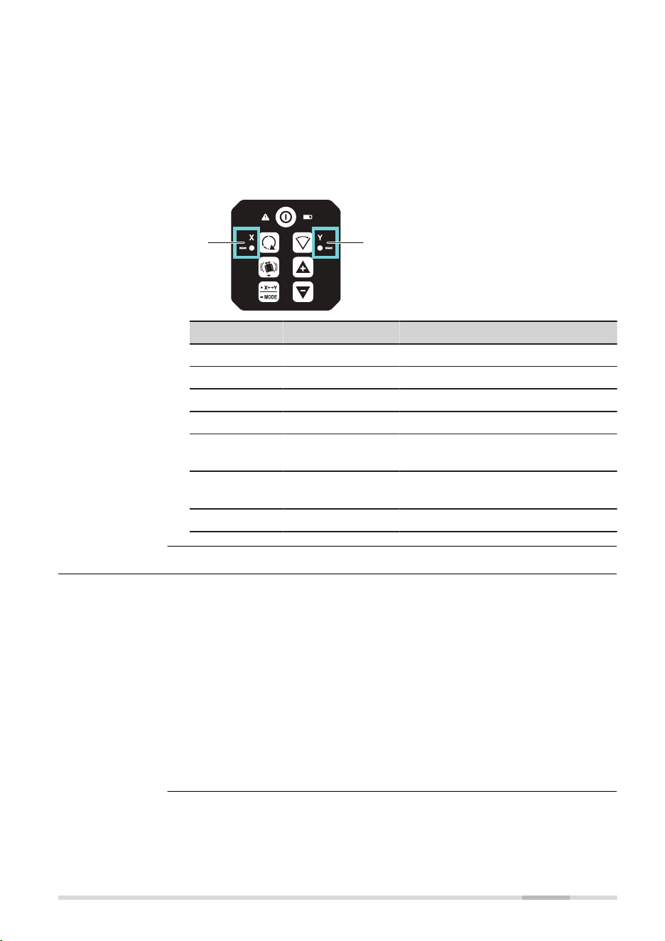
The status of the X/Y‑axis LED depend on the current function selected:
•
Horizontal use.
Refer to 3.6 Horizontal Use for details
•
Laydown use
Refer to 3.7 Layout/Laydown Use for details
•
H.I.Alert
Refer to 3.8 Height of Instrument Alert (H.I.Alert) function for details
•
Accuracy Adjustment
Refer to 7 Accuracy Adjustment for details
27865_001
ab
a X-axis LED
b Y-axis LED
X/Y Colour X/Y Status Mode/Status
Green Solid Levelled/automatic.
Green Slow ashing Waiting to be levelled.
Red Solid Manual/not levelled.
Red Slow ashing Axis can be tilt with arrow buttons.
Red Fast ashing, 2 Hz ALARM indication:
Device moved with H.I.Alert active.
Red Fast ashing,
both alternating
ALARM:
Device in wrong laydown position.
Orange Flashing Device in scan mode.
3.3 Turning the SKR001 On and Off
Press the Power button to turn on or off the SKR001.
☞
Device indicates turn on with short beep.
After turning on:
• If set up within the ±5° self-levelling range (horizontal or vertical), the
SKR001 automatically levels to create an accurate horizontal plane of
laser light
•
Once levelled, the head starts rotating and SKR001 is ready for use
•
After 30 seconds of completing the levelling, the H.I.Alert system
becomes active to protect the laser against changes in elevation
caused by movement or settling of the tripod
•
The self-levelling system and H.I.Alert function continues to monitor
the position of the laser beam to ensure consistent and accurate work
X/Y‑axis LED
Description
Operation 21
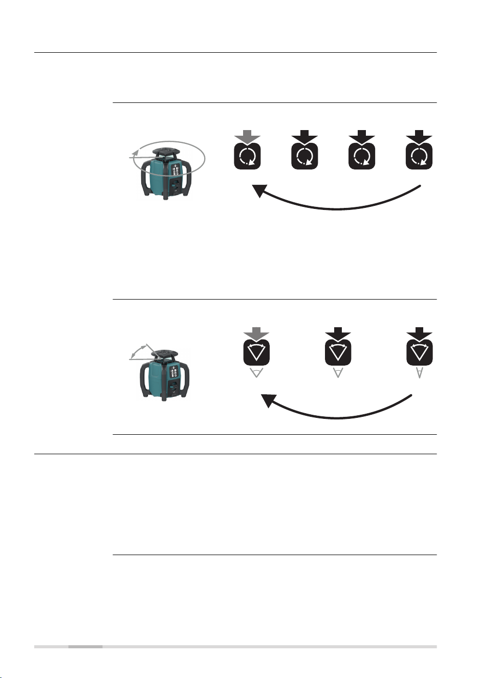
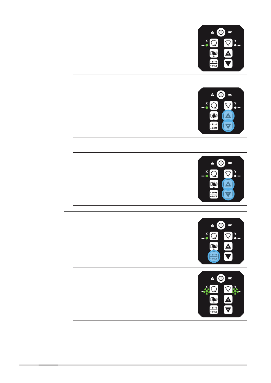
3.4 Automatic Mode
The SKR001 always starts up in Automatic Mode.
In Automatic Mode the SKR001 automatically levels if set up within the 5°
self-levelling range (horizontal or laydown).
Push the Head speed button:
3x
600 rpm
1x 2x
4x
300 rpm150 rpm0 rpm
27869_002
☞
If rotation speed is set to 0, the head is not rotating and only a
laser dot is visible.
☞
The dot can only rotate by using up/down button horizontal use
AND if SKR001 is in automatic mode!
If device is in laydown mode, single slope or manual mode, the
up/down buttons are to tilt axis and cannot rotate the dot!
Push the Scan mode button:
30° 20° 10°
3x
1x 2x
27870_002
3.5 Manual Mode
After start-up the Manual Mode can be activated. In Manual Mode, the self-
levelling is deactivated. The following options are available:
•
Change the X-axis to Manual Mode/single axis slope mode
•
Change the Y-axis to Manual Mode/single axis slope mode
•
Change to Full Manual Mode/dual axis slope mode
☞
After turning the SKR001 off and on again, the SKR001 is in
Automatic Mode.
Description of the
Automatic Mode
Change the rota-
tion speed, in loop
Change the scan
angle, in loop
Manual mode
22 Operation
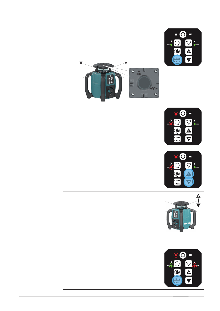
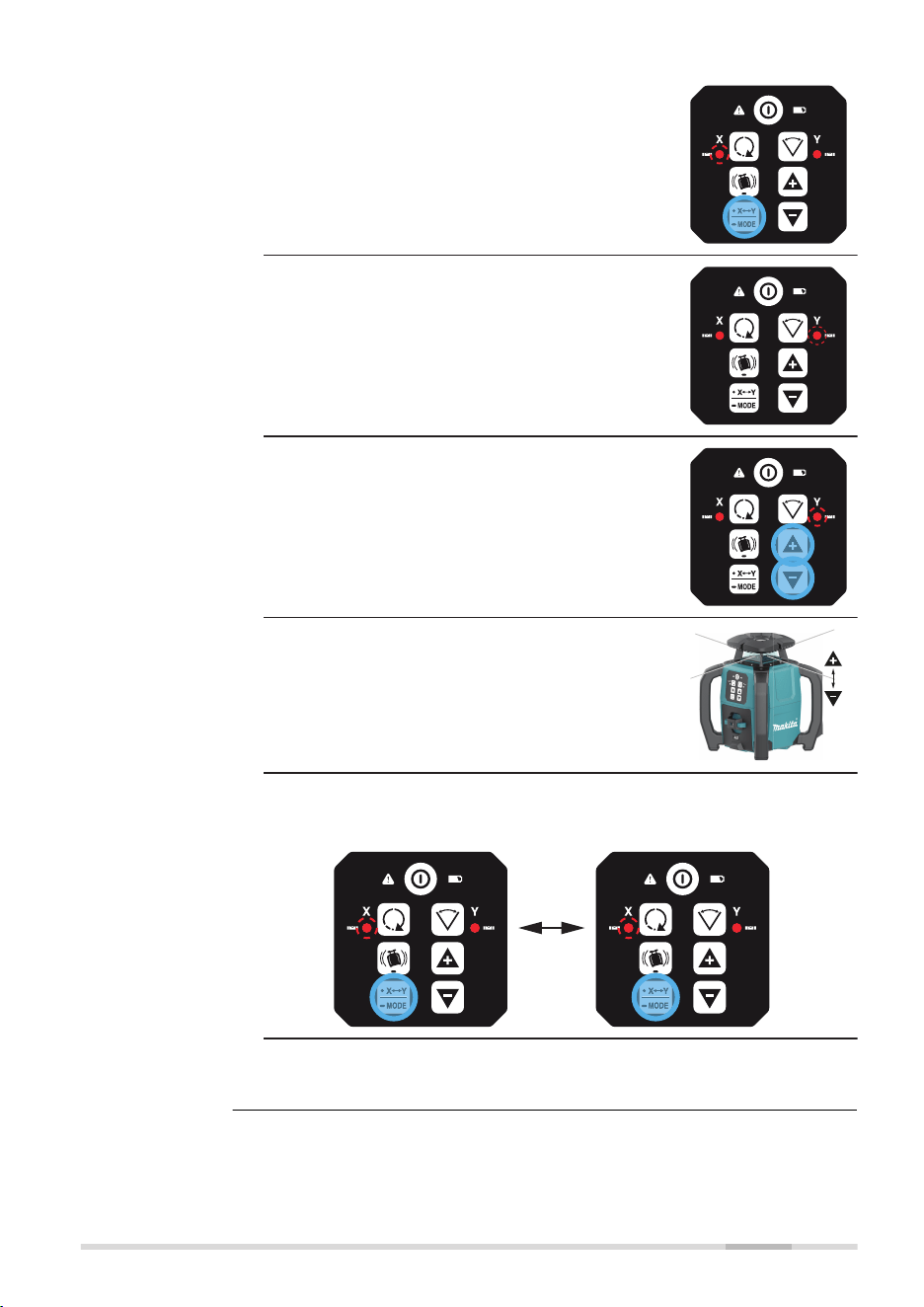
Changing the X‑axis to single axis slope mode
1. After startup, long press the X/Y‑Mode but-
ton to change the X‑axis to single axis
slope mode.
☞
The X-axis and Y-axis are
marked on the top of the
SKR001.
28004_001
L
☞
X-axis in single axis slope mode:
•
The H.I.Alert LED is slow ashing red.
•
The X-axis LED is slow ashing red.
•
The Y‑axis LED is green and continues
to self-level.
!
2. Press the Up/Down button to incre-
ment/decrement the slope for the X‑axis.
!
☞
The slope of the X-axis moves upwards or
downwards as illustrated.
27433_001
X-axis
Changing the Y‑axis to single axis slope mode
1. Press the X/Y‑Mode button again to change
the Y‑axis to single axis slope mode.
!
Change the X/Y-
axis to Manual
Mode/single axis
slope mode
Operation 23
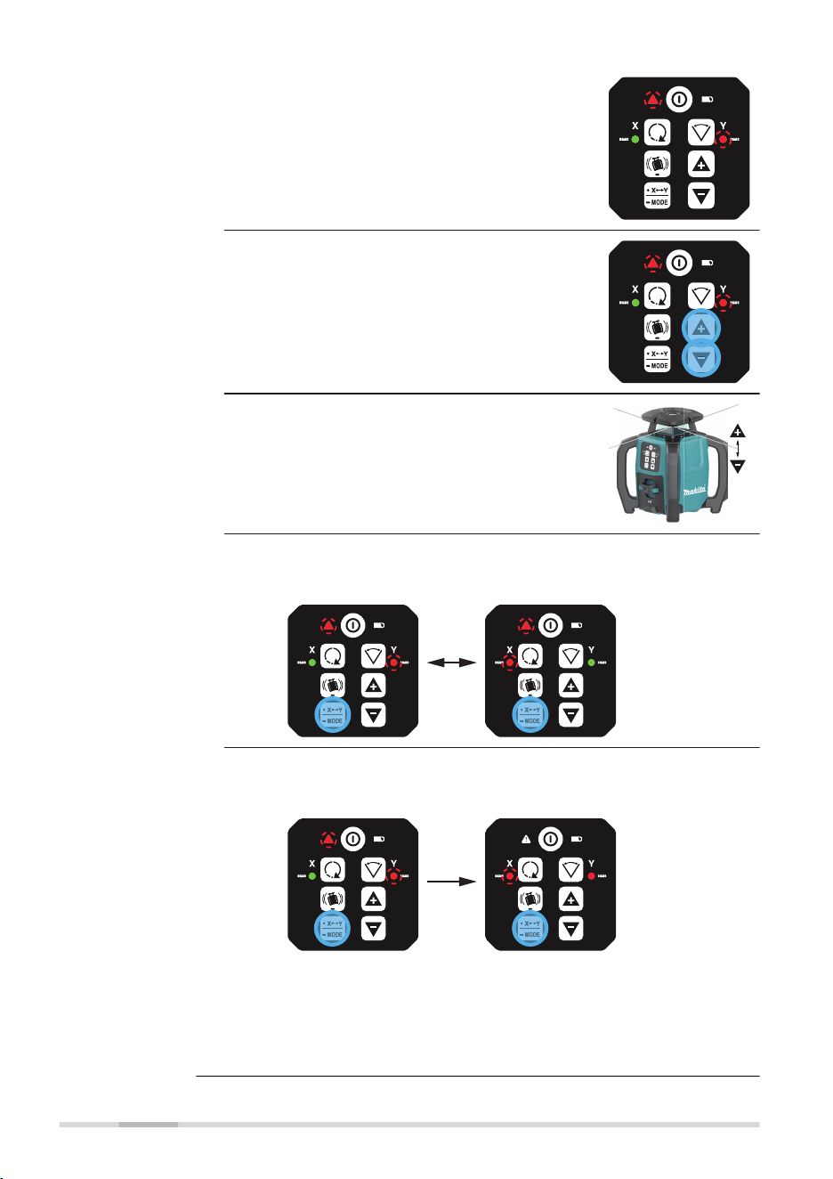
☞
Y-axis in single axis slope mode:
•
The H.I.Alert LED is slow ashing red.
•
The Y-axis LED is slow ashing red.
•
The X‑axis LED is green and continues
to self-level.
!
2. Press the Up/Down button to incre-
ment/decrement the slope for the Y‑axis.
!
☞
The slope of the Y-axis moves upwards or
downwards as illustrated.
27553_001
Y-axis
3. Option:
Push the X/Y‑Mode button to toggle between X‑axis or Y‑axis in
single axis slope mode.
! !
4. Option:
Long push the X/Y‑Mode button to switch to Dual Axis Slope
Mode.
!
!
L
☞
Refer to Change to Full Manual Mode/dual axis slope
mode for details.
☞
Long push the X/Y‑Mode button to return to Auto-
matic Mode.
24 Operation
3.6 Horizontal Use
Refer to chapter 5.1 up to chapter 5.4 for details.
3.7 Layout/Laydown Use
Refer to chapter 5.5 for details.
27976_001
When device is in normal laydown
position, keypad upwards:
•
X‑axis LED is solid green, if
levelled
•
Y‑axis LED ashes red, normal
laydown
27977_001
When device is in wrong laydown
position, keypad sidewards:
•
X‑axis LED and Y‑axis LED
ash at 2 Hz alternating to
alert failure
•
Additional beep alarm
This alert is same during normal
use but also during calibration.
3.8 Height of Instrument Alert (H.I.Alert) function
•
The H.I.Alert function prevents incorrect work caused by movement or
settling of the tripod that would cause the laser to level at a lower
height.
•
The H.I.Alert function becomes active, 30 s after intialisation and level-
ling of the SKR001. The H.I.Alert monitors the movement of the laser.
•
The alert LED is slow ashing during initialisation
•
Once levelled, the head of the laser starts rotating
•
If the H.I.Alert is active, the LED is fast ashing at 2 Hz
•
The H.I.Alert monitors the laser. If disturbed, both the X-axis LED and
Y-axis LED ash alternately together with the H.I.Alert LED. The SKR001
beeps rapidly.
•
To stop the alert turn SKR001 off and on again. Check the height of
the laser before beginning to work again.
☞
The H.I.Alert function turns on automatically every time the
SKR001 is turned on.
The H.I.Alert function can be disabled or enabled by pressing the following
button combination:
1.
If H.I.Alert is activated, long press the H.I.Alert button to deactivate.
2.
To activate again, long press the H.I.Alert button.
Desription
Description
Laydown orienta-
tion detection
Description of the
H.I.Alert function
Disable/enable the
H.I.Alert function
Operation 25
Initialisation (30 s):
LED slow ashing 1 Hz
!
Armed/activated:
LED solid
!
Alarm:
Alert LED, red - fast ashing, 2 Hz and
X‑axis LED and Y‑axis LED with a beep
alarm.
!
Changing to dual axis slope mode
1. In Single Slope Mode, long press the X/
Y‑Mode button to enter the dual axis slope
mode.
!
L
☞
Dual axis slope mode, X tilting, Y tilted:
•
The H.I.Alert LED is OFF.
•
The X-axis LED is slow ashing red.
No self-level.
•
The Y‑axis LED is red. No self-level.
2. Press the Up/Down button to incre-
ment/decrement the slope for the X‑axis.
☞
The slope of the X-axis moves upwards or
downwards as illustrated.
27433_001
X-axis
H.I.Alert indicator
LED
Change to Full
Manual Mode/dual
axis slope mode
26 Operation
3. Option:
Press the X/Y‑Mode button again to tilt the
Y‑axis.
☞
Dual axis slope mode, X tilted, Y tilting:
•
The H.I.Alert LED is OFF.
•
The X-axis LED is red. No self-level.
•
The Y‑axis LED is slow ashing red.
No self-level.
4. Press the Up/Down button to incre-
ment/decrement the slope for the Y‑axis.
☞
The slope of the Y-axis moves upwards or
downwards as illustrated.
27553_001
Y-axis
5. Option:
Push the X/Y‑Mode button to toggle between X‑axis or Y‑axis in
dual axis slope mode.
!
6. Long press the X/Y-Mode button to return
to Automatic Mode.
Operation 27
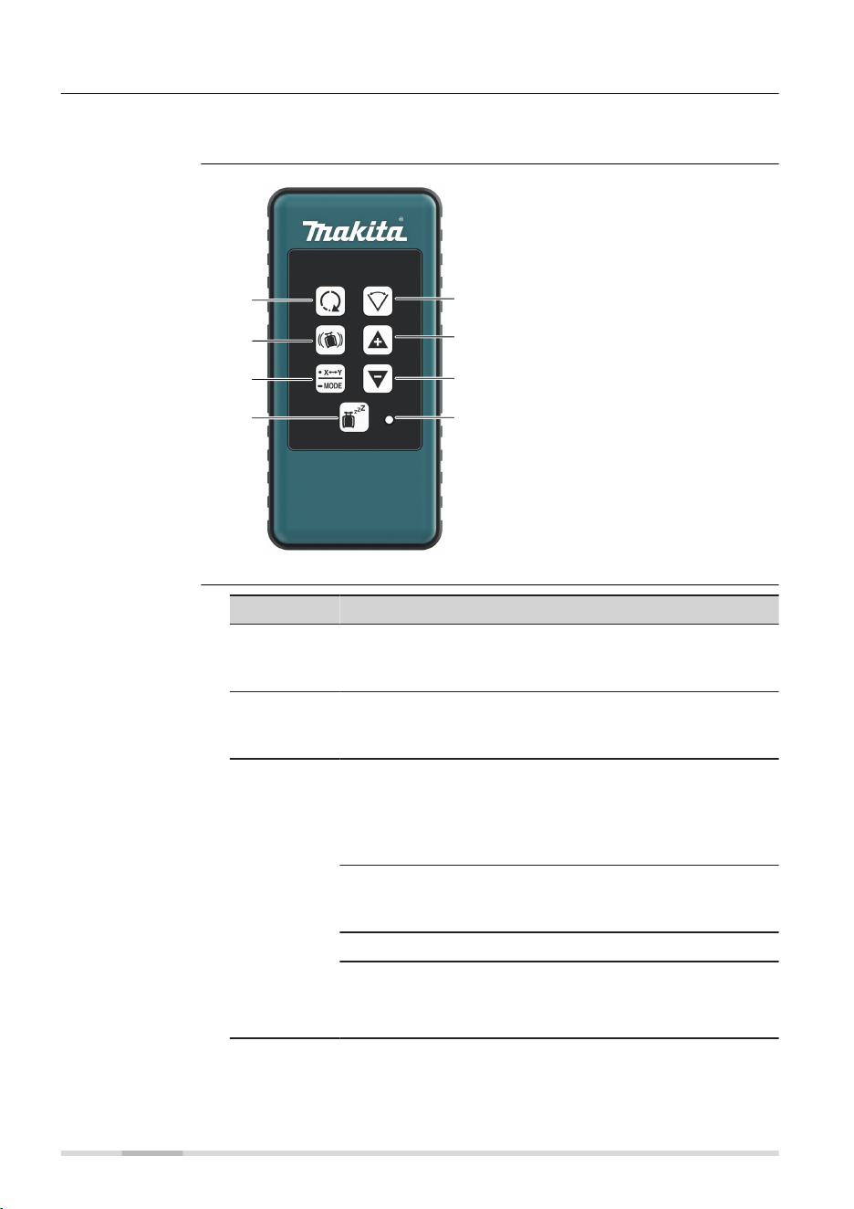
3.9 RC1 Remote Control
The RF Remote Control communicates with the SKR001 via RC (radio) and is
used to control the same functions as on the laser.
27425_001
g
h
e
f
a
b
c
d
a Head speed
b H.I.Alert
c Automatic/Manual Mode,
select axis
d Sleep mode
e Scan mode
f Up
g Down
h Sending LED
Button Function
Head speed Press to change speed (in loop):
600 → 0/150/300/600 rpm
Refer to Change the rotation speed, in loop for details.
H.I.Alert Long press H.I.Alert button to activate/deactivate
H.I. Alert.
Refer to Description of the H.I.Alert function for details.
Automatic/
Manual
Mode,
select axis
Single axis slope mode:
Long press once to change the X‑axis to manual mode
with Y‑axis self-levelling.
Press again to change the Y‑axis to manual mode with
X‑axis self-levelling.
Dual axis slope mode:
Long press again to change both axes to manual mode
with no self-levelling.
Long press again to change back to automatic mode.
☞
Note the changes in the LED indicators in the
manual modes. The red LED indicates that
the corresponding axis is in manual mode.
Description
RC1 Remote Con-
trol panel
Description of the
buttons
28 Operation

Button Function
Sleep mode Press to put the SKR001 in sleep mode.
•
During Sleep Mode, all functions are disabled
•
The low battery indicator lights green or ashes
green depending on battery power. All other LED are
off
•
The SKR001 sleeps for 2 hours, then shuts down
automatically and must be turned on again at the
laser
•
When in Sleep Mode pressing the sleep button
wakes the SKR001 and operation resumes same as
before sleep mode
Scan mode Short press Scan button to activate scan mode.
Short press Scan button to change angle (in loop):
30° → 20°/10°/30°.
Refer to Change the scan angle, in loop for details.
Up and
Down
Rotates the scan area or tilt the axis/laser beam depend-
ing on the operating mode.
Sending LED:
The sending LED ashes to indicate that the remote is sending a signal to
the SKR001.
3.9.1 Pairing the SKR001 with the RC1 Remote Control
The SKR001 and the RC1 Remote Control include radio devices that allow the
user to activate more functions on the SKR001.
When purchased together, the SKR001 and the RC1 have been paired
together at the factory. Should it be necessary to pair your units after pur-
chase, the following information is applicable.
Before using the RF features, the SKR001 and the Remote Control must rst
be paired together to be able to communicate with each other.
1. Turn off the SKR001.
2. Press and hold the Power button on the SKR001 to turn it on
(5 sec).
3. Press and hold the Head Speed button and the Scan Mode button
on the RC1.
☞
The SKR001 beeps ve times quickly and the X and Y LED indicat-
ors ash green when the pairing was successful.
Pairing step-by-
step
Operation 29
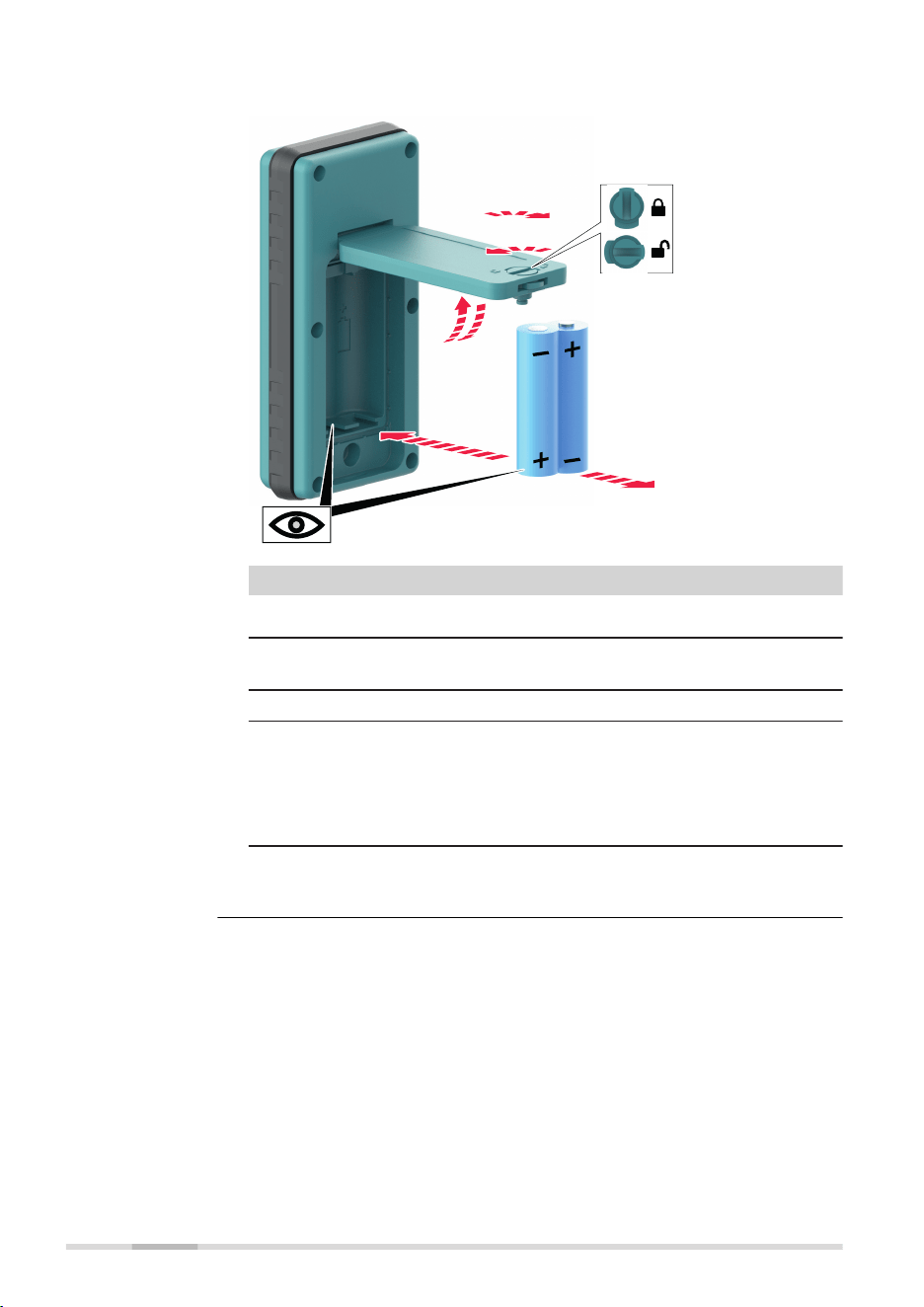
The LED ashes when the batteries are low.
27998_001
1a
1b
2b
2a
3a
3b
Step Description
☞
The batteries are inserted under the battery door.
1. Turn the locking mechanism to the open position to open the
battery door.
2. Remove the batteries from the battery compartment.
To insert the batteries: Insert the batteries into the battery
compartment, ensuring that the contacts are facing in the
right direction.
☞
The correct polarity is displayed inside the bat-
tery compartment.
3. Close the cover of the battery compartment and turn the lock-
ing mechanism to the closed position to lock the battery door.
Changing the
alkaline batteries,
step‑by‑step
30 Operation
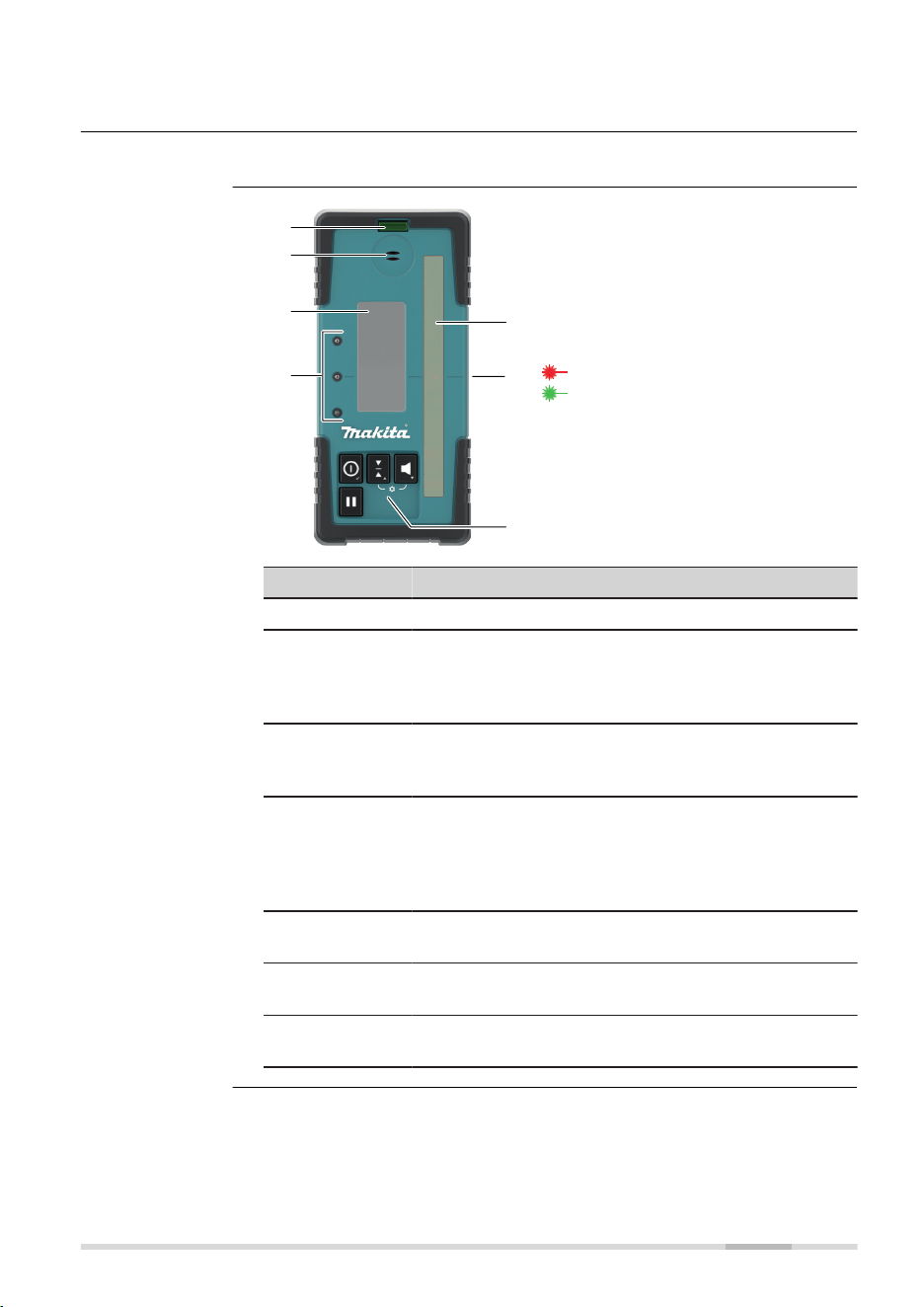
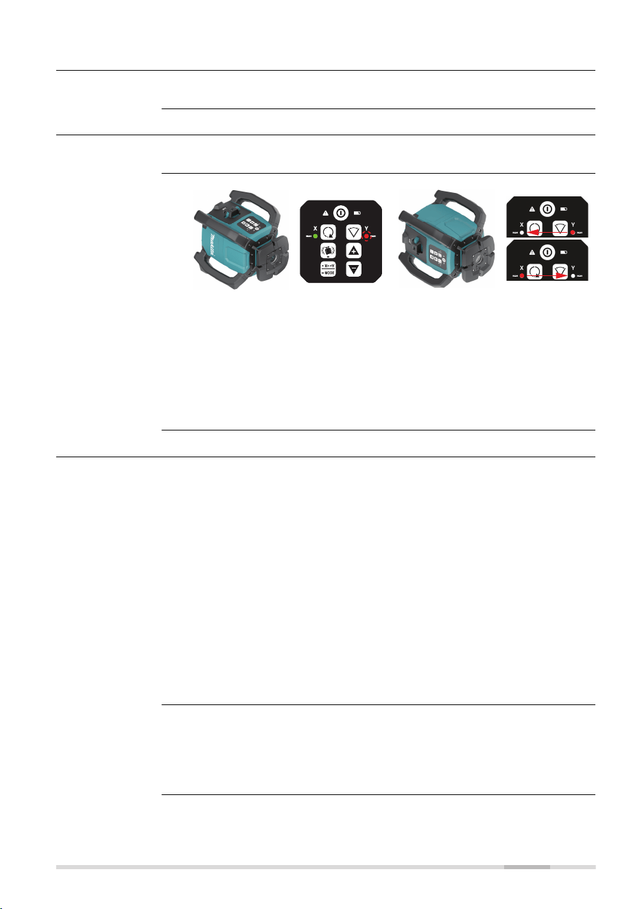
4 LDX2 Digital Receiver
The SKR001 is sold with the LDX2 Digital Receiver.
27434_001
a
e
f
g
b
c
d
Working spectrum:
Red laser beam
Green laser beam
a Level vial
b Audio speaker
c LCD window
d LED
e Laser reception window
f Offset notch/on-grade
g Keypad
Component Description
Level vial Aids to keep the rod plumb when taking readings.
Audio Speaker Indicates the position of the detector:
•
High - Fast beeping
•
On-grade - Solid tone
•
Low - Slow beeping
LCD window Front and rear LCD arrow indicate the position of
the receiver and numeric deviation of laser to offset
notch/on‑grade. Refer to Technical data for details.
LEDs Display the relative position of the laser beam. Three
channel indication:
•
High - Red
•
On-grade - Green
•
Low - Blue
Laser Reception
window
Detects the laser beam. The reception windows must
be directed towards the laser.
Offset notch/
on‑grade
Indicates the on-grade position of the laser.
Keypad Power, accuracy and volume functions. Refer to
Description of the buttons for detailed information.
Description
Instrument
components,
part 1 of 2
LDX2 Digital Receiver 31
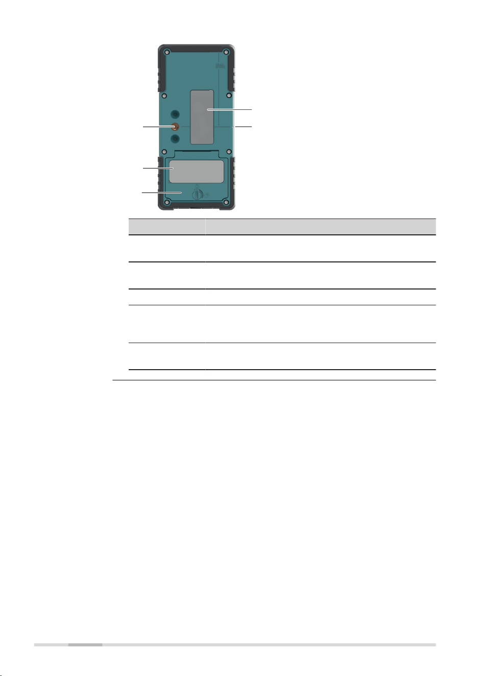
27435_001
e
d
c
b
a
a Bracket mounting hole
b Type label
c Battery door
d LCD window
e Offset notch/on-grade
Component Description
Bracket Mount-
ing Hole
Location to attach the receiver bracket for normal
operation.
Type label The serial number is located inside the battery com-
partment.
Battery door Access to the battery compartment.
LCD window Front and rear LCD arrow indicate the position of
the detector and numeric deviation of laser to Offset
notch/on‑grade.
Offset notch/
on‑grade
Use to transfer reference marks. The notch is 85 mm
(3.35") below to top of the receiver.
Instrument
components,
part 2 of 2
32 LDX2 Digital Receiver
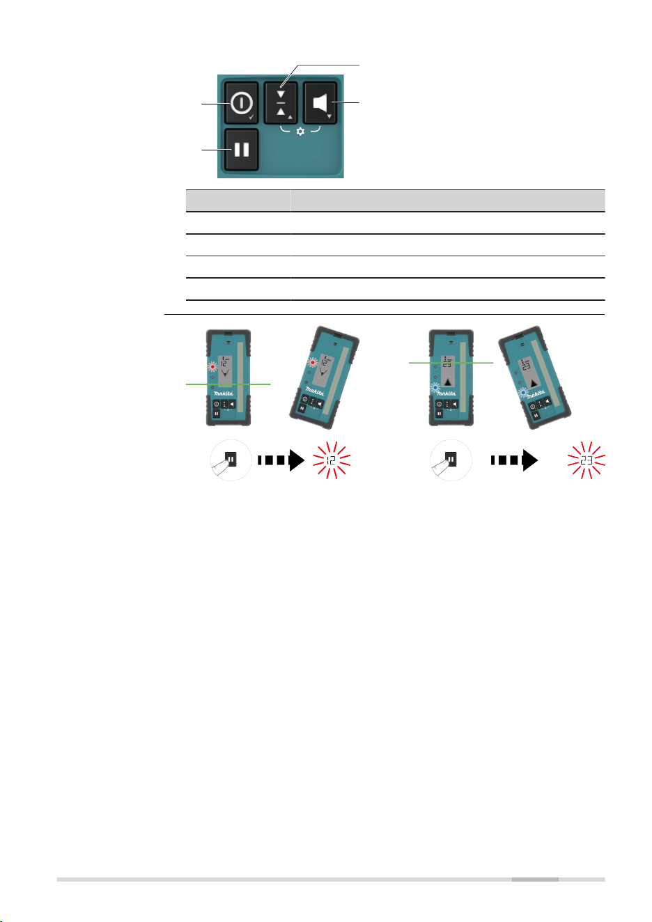
27436_001
a
b
c
d
a Power
b Hold value
c Sensitivity
d Audio
Button Function
Power Press once to turn on the receiver.
Hold value Press to capture digital reading.
Sensitivity Press to change detection sensitivity.
Audio Press to change the audio output.
Description of the
buttons
Hold value
LDX2 Digital Receiver 33

To access the menu, press the Sensitivity button and Audio button simultan-
eously.
•
Use the Sensitivity button and Audio button to change parameters.
•
Use the Power button to scroll through the menu.
Menu Function Indication
UNT Changes the unit of meas-
ure for the digital readout.
Units - mm/cm/in/ft
☞
Active unit
ashes.
LED Changes the brightness of
the LED indicators.
LEDs - High/Low/Off
DRO Turns on or off the digital
readout.
Green LED is on: digital
readout is on.
Red LED is on: digital
readout is off.
☞
DRO ashes.
BAT Turns on or off the Laser
low battery indication on
the receiver.
Green LED is on: Laser
low battery icon function is
active.
Red LED is on: Laser low
battery icon function is not
active.
☞
SKR001 icon
ashes.
MEM Turns on or off the position
memory function.
Green LED is on: function is
on.
Red LED is on: function is
off.
☞
Full down
arrow ashes.
RPS Measures the head speed
of the laser.
☞
Hold in rotat-
ing beam to
measure the
head speed.
Measured head speed is
displayed.
Feature Description
Strobe rejection The RE Digital is designed to reject and eliminate
unwanted signals from strobe lights.
Beam nding Passing the RE Digital through the laser beam will
cause the sensor to beep twice quickly.
Menu access and
navigation
Menu
Special features
34 LDX2 Digital Receiver
Feature Description
Out of beam
display
If the receiver is moved out of the receiver range, the
arrow display will indicate the direction to move to
return to the laser beam.
Laser low bat-
tery
Alerts the user when the lasers’s batteries are getting
low.
The small battery icon appears empty on the LDX2 display when the batter-
ies are low and need replacement.
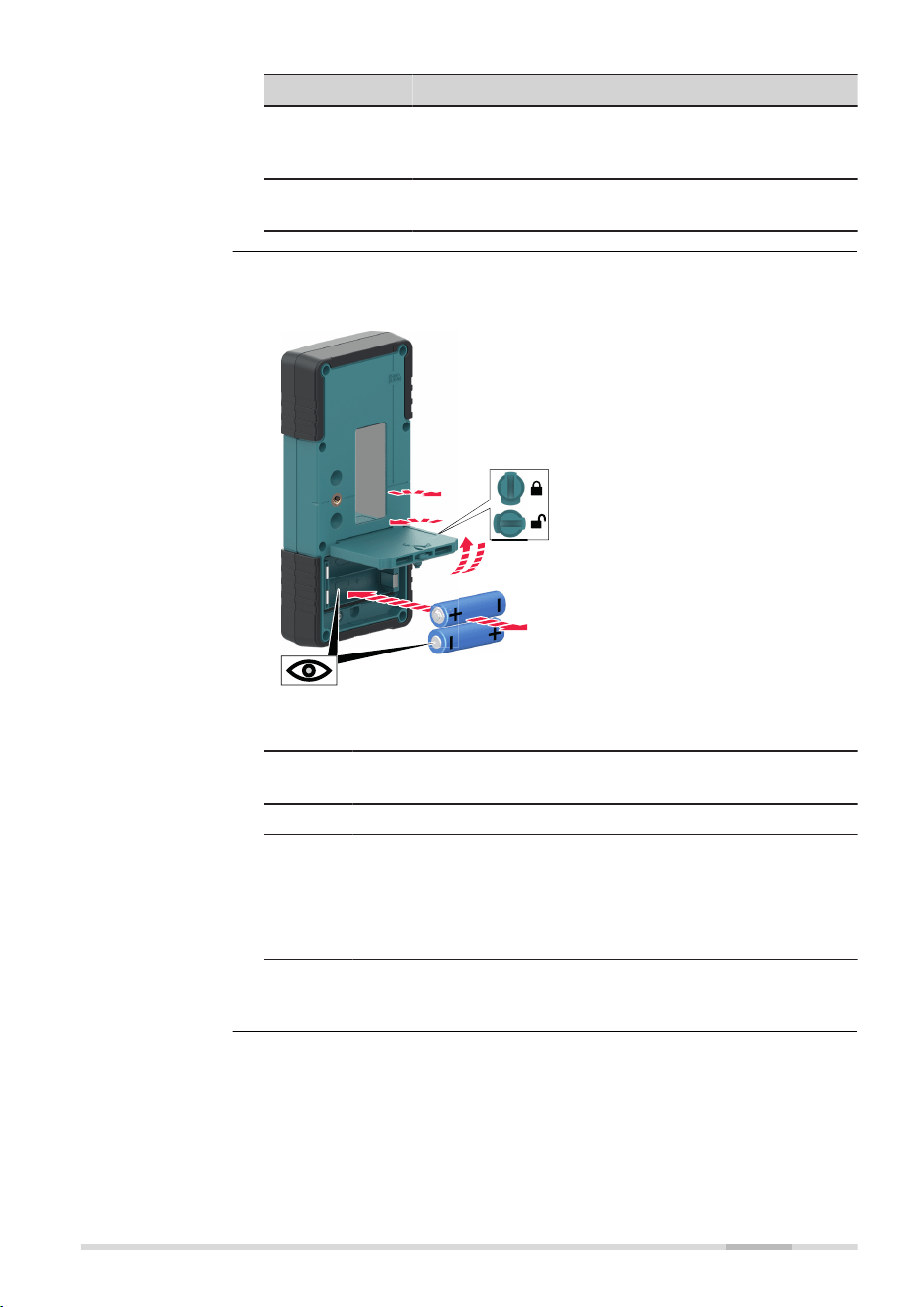
27971_001
1a
1b
2b
2a
3a
3b
☞
The batteries are inserted under the battery door.
1. Turn the locking mechanism to the open position to open the
battery door.
2. Remove the batteries from the battery compartment.
To insert the batteries: Insert the batteries into the battery
compartment, ensuring that the contacts are facing in the
right direction.
☞
The correct polarity is displayed inside the bat-
tery compartment.
3. Close the cover of the battery compartment and turn the lock-
ing mechanism to the closed position to lock the battery door.
Changing the
alkaline batteries,
step-by-step
LDX2 Digital Receiver 35
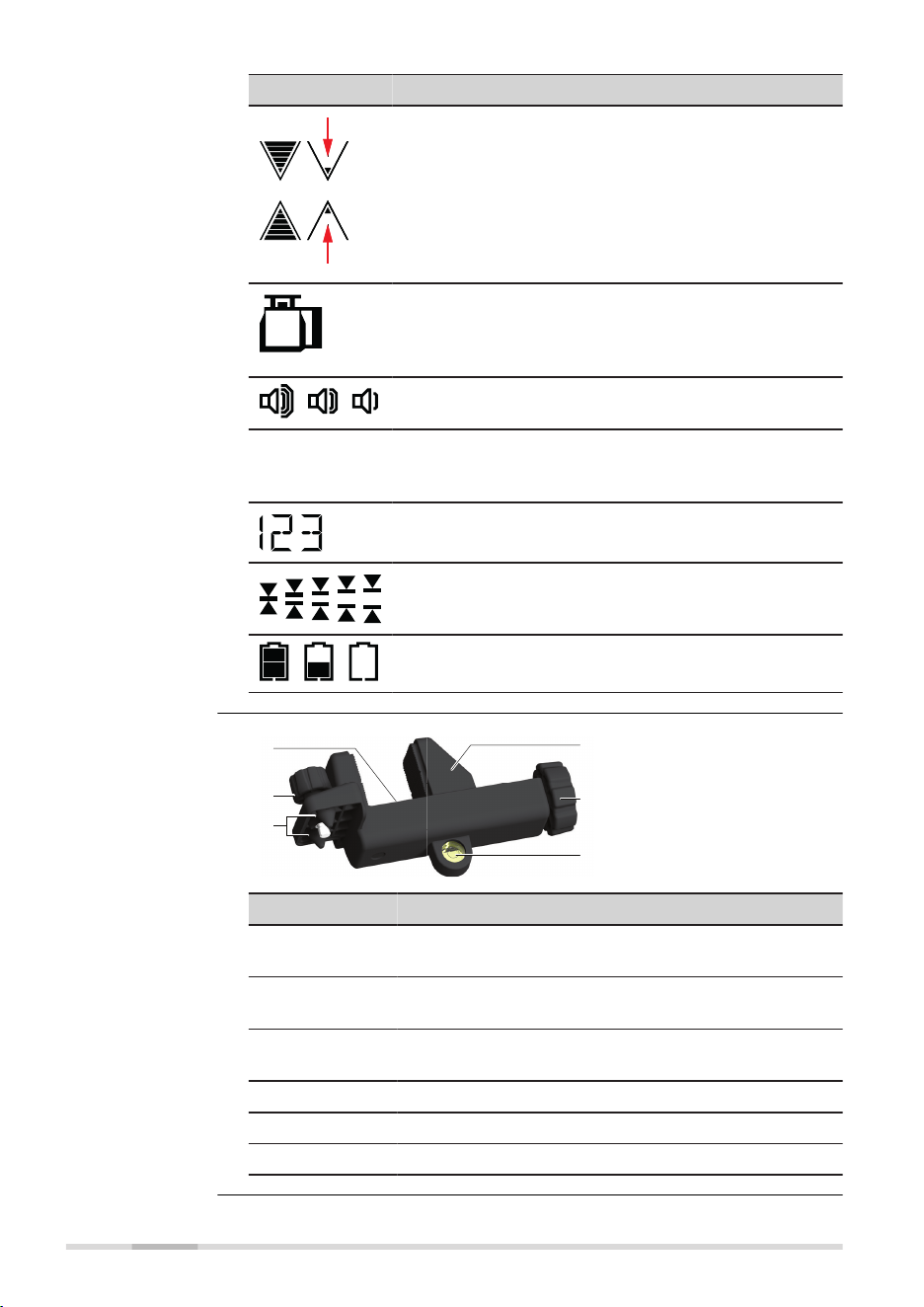
Icon Description
Grade indication arrow - seven channels are dis-
played for above and below grade.
•
Arrow bars can be selected to represent the
selected detection sensitivity.
•
Memory Display - if the receiver is moved out of
the detection range, the arrow display indicates
the direction to move to return to the laser beam
(see MEM in menu to enable/disable).
Laser low battery warning - the SKR001 icon is dis-
played when the battery of the laser unit is almost
depleted. This feature is laser dependent (see BAT in
menu to enable/disable).
Audio volume indication - four levels of volume are
displayed: loud, medium, soft, off (no icon).
mm
ft
in
cm
Units of measure - ve units of measure are dis-
played: mm (millimeter), cm (centimeters), in (inch), in
(fractions), ft (feet).
Elevation indication - numeric value is displayed
(dependent on the unit of measure chosen).
Detection sensitivity - ve levels of accuracy are dis-
played: Very ne, Fine, medium, Coarse, Very coarse.
Receiver low battery warning - three levels of bat-
tery life are displayed: full, low, empty.
004957_002
a
b
c
d
e
f
a On-grade refer-
ence
b Attachment knob
c Alignment points
d Locking clamp
e Locking knob
f Level vial
Component Description
On-grade
reference
The top edge of the bar aligns with the on-grade posi-
tion.
Attachment
knob
Attaches the clamp to the back of the receiver.
Alignment
points
Aligns and secures the clamp.
Locking clamp Holds the receiver and bracket to the grade rod.
Locking knob Turn to tighten the locking clamp to the grade rod.
Level vial The aids to keep the rod plumb when taking readings.
LCD Display
Receiver bracket
36 LDX2 Digital Receiver
5 Applications
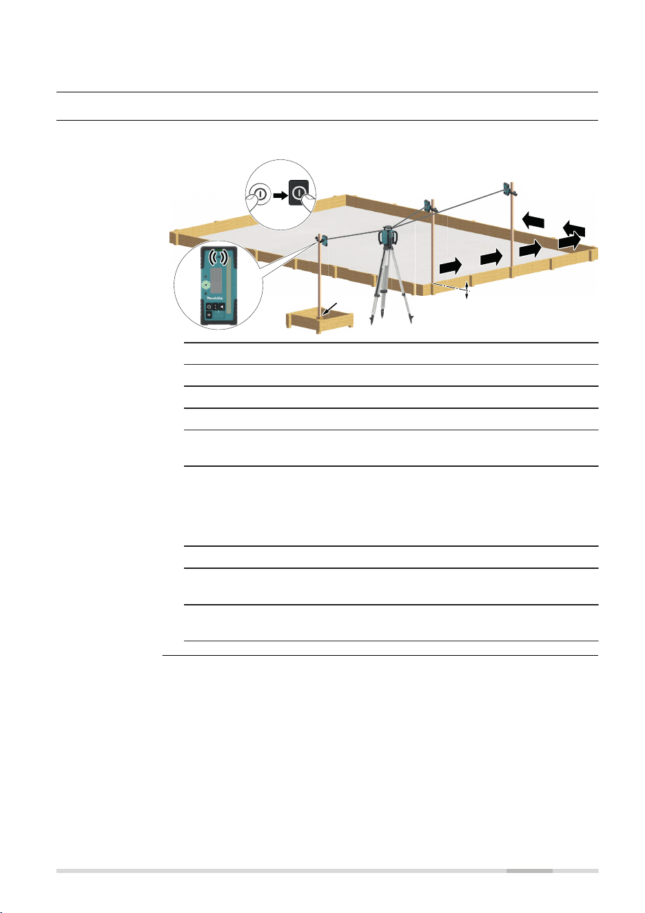
5.1 Setting Forms
Application shown using the LDX2 Digital Receiver.
ba
4
27437_001
6
5
7
8
9
1 + 2
3
1. Set up the SKR001 on a tripod.
2. Set up the tripod on a stable surface outside the working area.
3. Attach the receiver to a rod.
4. Turn on the SKR001 and the receiver.
5. Set the base of the rod on a known point for the nished height
of forms.
6. Adjust the height of the receiver on the rod until the offset
notch/on-grade position is indicated on the receiver by:
•
the centre bar
•
the green ashing LED
•
a solid audio tone
7. Set the rod with the attached receiver on top of the form.
8. Adjust the height of the form until the offset notch/on-grade pos-
ition is again indicated.
9. Continue to more positions until the forms are levelled to the
rotating plane of the SKR001.
Setting Forms,
step by step
Applications 37
5.2 Checking Grades
Application shown using the LDX2 Digital Receiver.
6
ba
27438_001
3
1 + 2
4
b)
c)
a)
1. Set up the SKR001 on a tripod.
2. Set up the tripod on a stable surface outside the working area.
3. Attach the receiver to a rod.
4. Turn on the SKR001 and the receiver.
5. Set the base of the rod on a known point for the nished grade.
6. Adjust the height of the receiver on the rod until the offset
notch/on-grade position is indicated on the receiver by:
•
The centre bar
•
The green ashing LED
•
A solid audio tone
7. Set the rod with the attached receiver on top of the excavation or
concrete pour to check for correct elevation.
8. Variances can be read from the digital receiver.
a)
Position is too high
b)
Position is on grade
c)
Position is too low
Checking Grades,
step‑by‑step
38 Applications
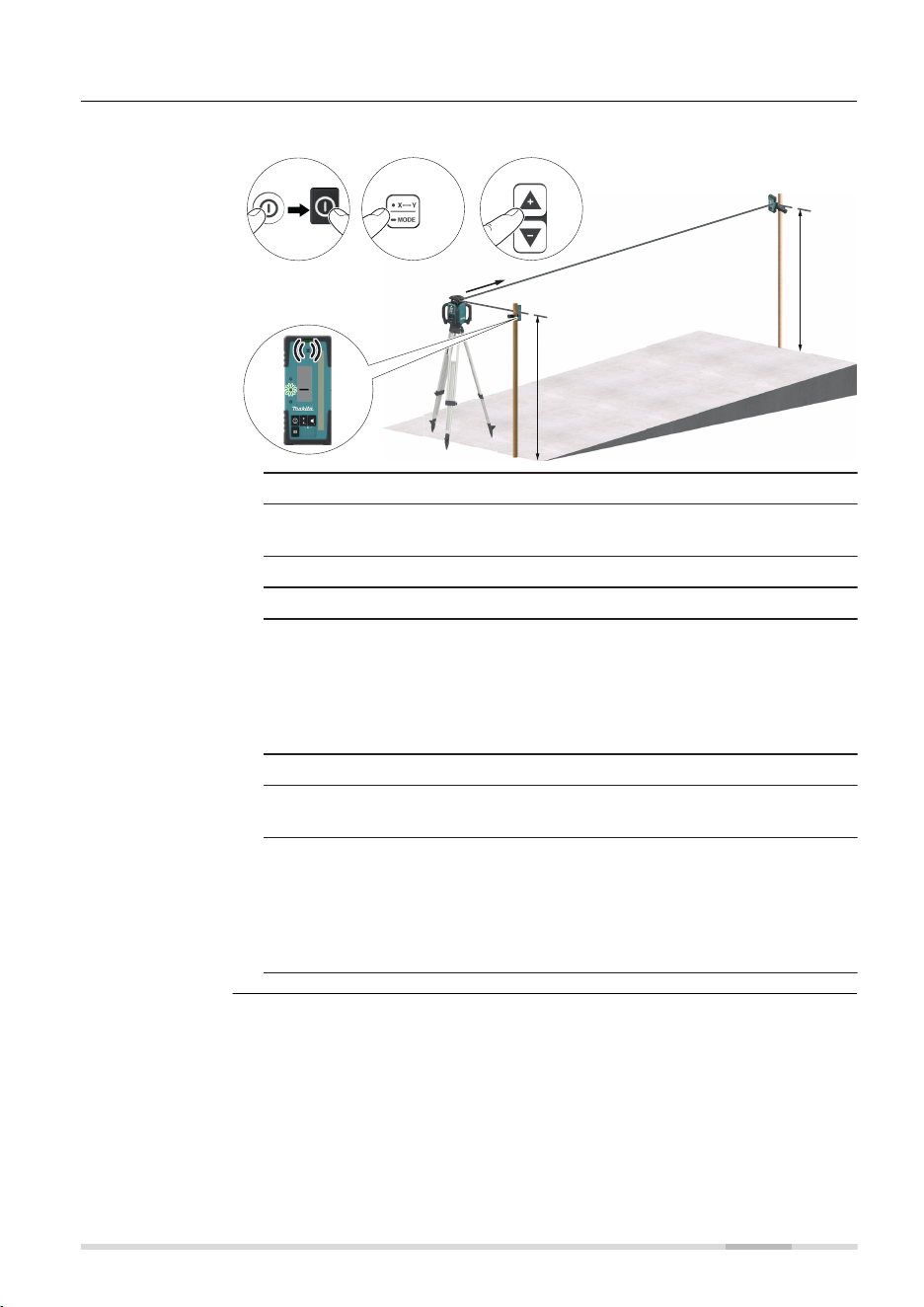
5.3 Manual Grades
Application shown using the LDX2 Digital Receiver.
1x
7 8
ba
27439_001
5
4
6
1 + 2
3
X
α
α
1. Set up the SKR001 on a tripod.
2. Set up the tripod at the base of a slope with the x-axis pointing in
the direction of the slope.
3. Attach the receiver to a rod.
4. Turn on the SKR001 and the receiver.
5. At the base of the slope, adjust the height of the receiver on the
rod until the offset notch/on-grade position is indicated on the
receiver by:
•
the centre bar
•
the green ashing LED
•
a solid audio tone
6. Move the rod and the attached receiver to the top of the slope.
7. Change the X-axis to Manual Mode by long press the Auto-
matic/Manual Mode button once on the SKR001.
8. Use the Left and Right Arrow buttons on the SKR001 to move the
laser beam up and down until the offset notch/on-grade position
is indicated on the receiver by:
•
the centre bar
•
the green ashing LED
•
a solid audio tone
Manual Grading,
step by step
Applications 39
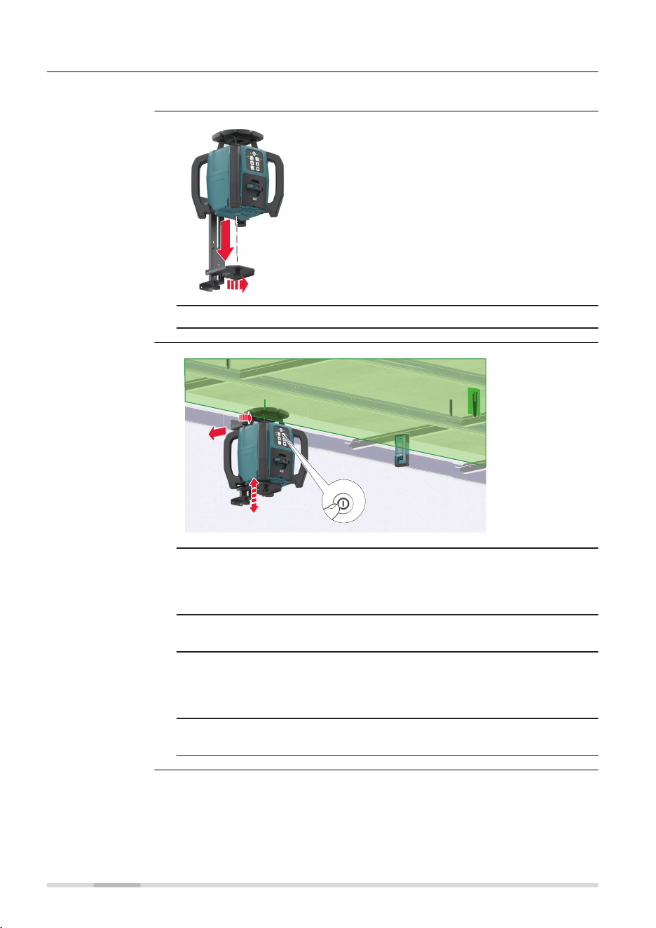
5.4 Suspended Ceilings
The SKR001 can also be used for suspended ceiling installations.
27440_001
1
1. Attach the SKR001 to the wall mount bracket.
27441_001
2
4
1b
3
1a
1. After mounting the rst strip of ceiling trim at the desired height
(centre position of the Target plate) below, attach the wall mount
bracket and laser to the trim. Tighten the locking knobs on the
top of the bracket.
2. Press the Power button to turn on the SKR001 and allow the
SKR001 to self-level.
3. Adjust the SKR001 so that the rotating beam is at the desired
height below the target plate. Loosen the adjustment knob on the
side of the bracket and slide the SKR001 up or down. When at the
desired height, retighten the adjustment knob.
4. Install the ceiling grid using the target plate and laser beam as
your reference.
Description
Mounting the laser
Application
40 Applications
Optional, use remote control to change scan or
rotation for improved visibility:
a Refer to Change the scan angle, in loop
for details.
b Refer to Change the rotation speed, in
loop for details.
27442_001
b
a
5.5 Layout/Laydown Mode
Lying on its side the SKR001 can be used for laying out wall positions,
squaring, transferring points and more. Refer to 3.7 Layout/Laydown Use for
details.
The SKR001 projects two laser beams at a 90° angle to each other.
5
2
27443_001
3
4
1
1. Place the SKR001 in the laydown position.
2. Press the power button to turn on the SKR001.
The SKR001 always turns on in Automatic Mode which is in lay-
down like single slope mode. Allow the X‑axis to self-level until
X LED is solid green, levelled. Y LED ashes red as not levelled and
can be adjusted.
3. In the laydown position, check the beam downwards for alignment
over your reference.
4. Start the head rotation or scanning motion to roughly align the
beam to a second control point. Refer to Change the X/Y-axis to
Manual Mode/single axis slope mode for details.
5. Using the buttons on the laser or the remote control, ne adjust
the beam until striking the second control point.
6. The rotating beam also creates a vertical plane for transferring
points from the oor to the ceiling.
Setup
Description
Layout/Laydown
Applications 41

In laydown position, use the Up and Down arrow
button to quickly align the vertical plane or plumb
beam to the second reference point.
27444_001
5.6 More Applications
Exterior Applications
•
Setting elevation of forms and footings
•
Squaring of forms
•
Checking elevations and benchmarks
•
Landscaping
•
Drainage and septic systems
•
Fences and retaining walls
•
Decks and patios
•
Simple driveways or small parking lots
•
Facade Installations
•
Batter board setups
Interior Applications
•
Suspended ceilings
•
Walls and partitions
•
Vertical alignment
•
Transferring points from oor to ceiling
•
Vertical plumb
•
Layout of oors
•
Squaring of angles
•
Setting cabinets
•
Chair rails and wainscoting
•
Alignment of wall and oor tiles
•
Trim carpentry
•
Setting sprinkler head heights
•
Sloped ceilings
Setup
More applications
42 Applications

6 Batteries
Operate the SKR001 with any Makita Li-Ion battery type LXT, CXT or XGT.
List the supported battery cartridge models:
•
BL1015/BL1016/BL1020B/BL1021B/BL1040B/BL1041B/BL1050B
•
BL1815N/BL1820/BL1820B/BL1830/BL1830B/BL1840/BL1840B/
BL1850/BL1850B/BL1860B
•
BL4020/BL4025/BL4040/BL4040F
Check the details of the model you have purchased.
☞
Some of the battery cartridges may not be available depending
on your region of residence.
6.1 Operating Principles
•
The battery must be charged before using it the rst time, because it
is delivered with an energy content as low as possible or might be in
sleep mode.
•
Charge the battery cartridge at room temperature at +10 °C to +40 °C/
+50 °F to +104 °F. At cold temperature, charging may not start
•
It is normal for the battery to become warm during charging. Using
the chargers recommended by Makita, it is not possible to charge the
battery once the temperature is too high
•
For new batteries or batteries that have been stored for a long time
(> three months), it is effectual to make a discharge/charge cycle
•
For Li-Ion batteries, a single discharge/charge cycle is sufcient. We
recommend carrying out the process when the battery capacity indic-
ated on the charger or on a Makita product deviates signicantly from
the actual battery capacity available.
• The batteries can be operated from −20 °C to +55 °C/−4 °F to +131 °F
•
Low operating temperatures reduce the capacity that can be drawn;
high operating temperatures reduce the service life of the battery
6.2 Battery for SKR001
1. Remove the Makita battery from the SKR001.
2. Charge externally with original Makita charger.
CAUTION
Battery tray not locked securely
If the battery tray is not locked securely, it may fall out of the SKR001
accidentally and might cause damage and injury.
Precautions:
▶
Install and lock the battery tray securely.
Description
First-time use/
charging batteries
Operation/dischar-
ging
Charging the Li-
Ion battery pack,
step‑by‑step
Batteries 43
The Low Battery Indicator LED on the SKR001 ashes when the batteries are
low and need to be charged. The charge indicator LED on the Lithium-Ion
battery pack indicates when the pack is being charged (ashing slowly) or fully
charged (on, not ashing).
27445_001
1
1
2
2
5
5
6
6
3
3
a
a
b
b
3
3
4
4b
b
b
4
4a
a
a
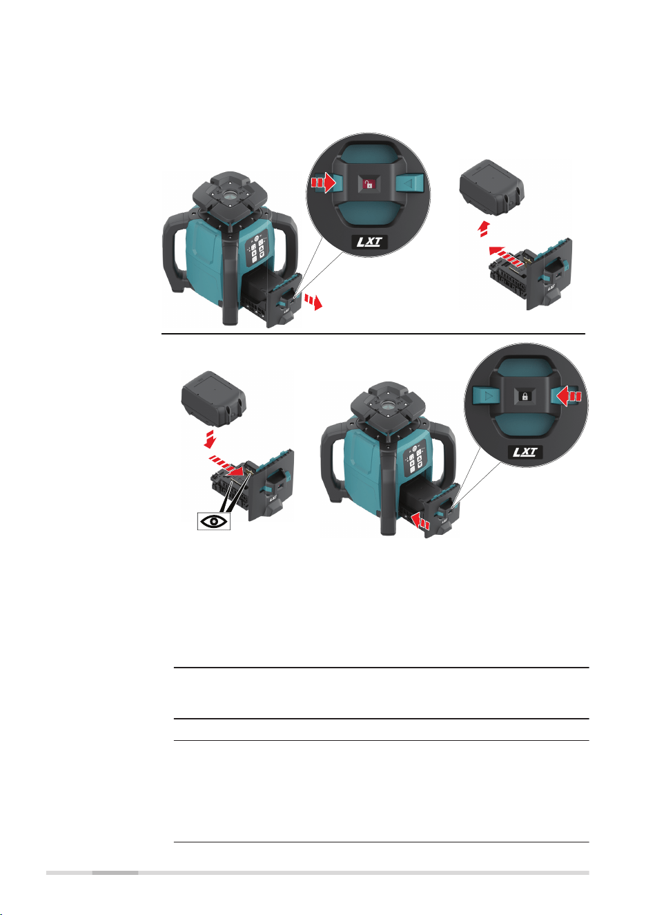
1. Always switch off the SKR001 before installing or removing of the
battery tray.
☞
Hold the tool and the battery tray rmly when
installing or removing battery tray. Failure to hold
the tool and the battery tray rmly may cause them
to slip off your hands and result in damage to the
tool and battery tray and a personal injury.
2. Slide the button (1) on the front of the battery tray to unlock
position.
To remove the battery tray, slide it out from the SKR001 (2).
3. Remove the battery cartridge from the battery tray (3).
4. Install the charged battery cartridge (4).
To install the battery cartridge, align the tongue on the battery
cartridge with the groove in the battery tray and slip it into place.
Insert it all the way until it locks in place.
☞
If you can see the red indicator on the upper side of
the button, it is not locked completely.
Installing or
removing bat-
tery cartridge,
step‑by‑step
44 Batteries

5. Install the battery tray into the SKR001 (5).
6. Always slide the button (6) on the front of the battery tray to lock
position and fully until the red indicator cannot be seen.
☞
If not, it may accidentally fall out of the tool, causing
injury to you or someone around you.
☞
Do not install the battery tray forcibly. If the battery tray does not
slide in easily, it is not being inserted correctly or foreign object
enters. Make sure that there is no foreign object inside and insert
it correctly.
Batteries 45
7 Accuracy Adjustment
•
It is the responsibility of the user to follow operating instructions
and to periodically check the accuracy of the laser and work as it
progresses.
•
The SKR001 is adjusted to the dened accuracy specication at the
factory. It is recommended to check the laser for accuracy upon
receipt and periodically thereafter to ensure accuracy is maintained.
If the laser requires adjustment, contact your nearest authorised ser-
vice centre or adjust the laser using the procedures described in this
chapter.
•
Only enter the accuracy adjustment mode when you plan to change
the accuracy. Accuracy adjustments should only be performed by a
qualied individual that understands basic adjustment principles.
•
It is recommended to perform this procedure with two people on a
relatively at surface.
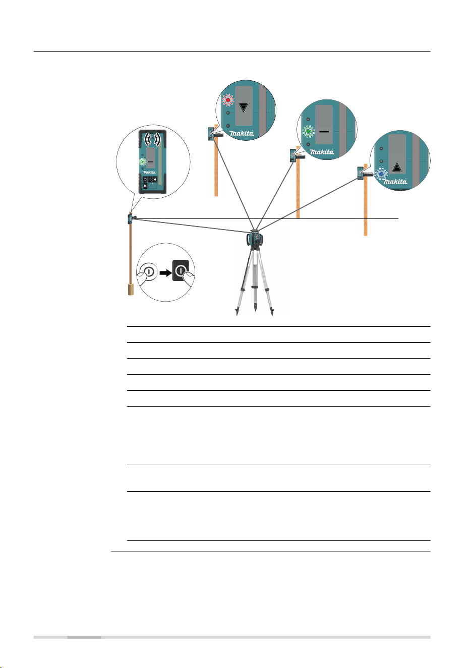
7.1 Checking the Level Accuracy
1. Place the SKR001 on a at, level surface or tripod approximately
30 m (100 ft) from a wall.
27447_001
30 m (100 ft)
30 m (100 ft)
X+
X—
2. Align the rst axis so that it is square to a wall. Allow the SKR001
to self-level completely (approximately 1 minute after the SKR001
begins to rotate).
3. Mark the position of the beam.
4. Rotate the laser 180° and allow it to self-level.
5. Mark the opposite side of the rst axis.
About
Checking the
level accuracy,
step‑by‑step
46 Accuracy Adjustment
27448_001
30 m (100 ft)
30 m (100 ft)
Y+
Y—
6. Align the second axis of the SKR001 by rotating it 90° so that
this axis is square to the wall. Allow the SKR001 to self-level
completely.
7. Mark the position of the beam.
8. Rotate the laser 180° and allow it to self-level.
9. Mark the opposite side of the second axis.
☞
If the four marks are within ±1.5 mm from the centre, the
SKR001 is within its accuracy specication
7.2 Adjusting the Self-Levelling Accuracy
7.2.1 Horizontal Position
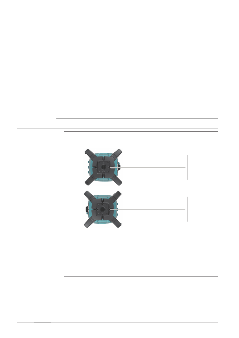
In Adjustment Mode the X-axis LED indicates changes to the X-axis.
27450_001
X
The Y-axis LED indicates changes to the Y-axis.
27449_001
Y
Description
Accuracy Adjustment 47
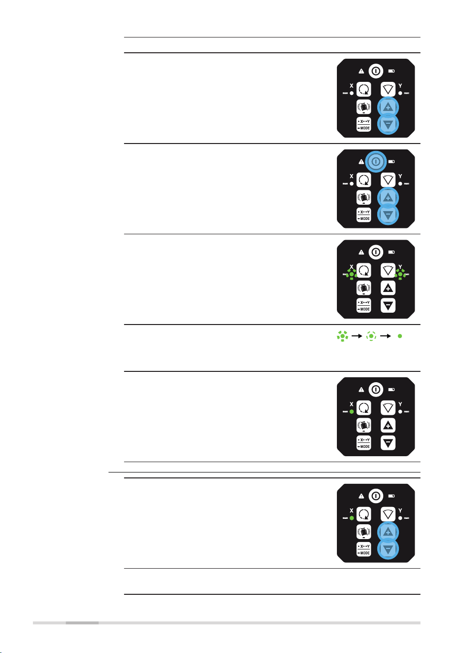
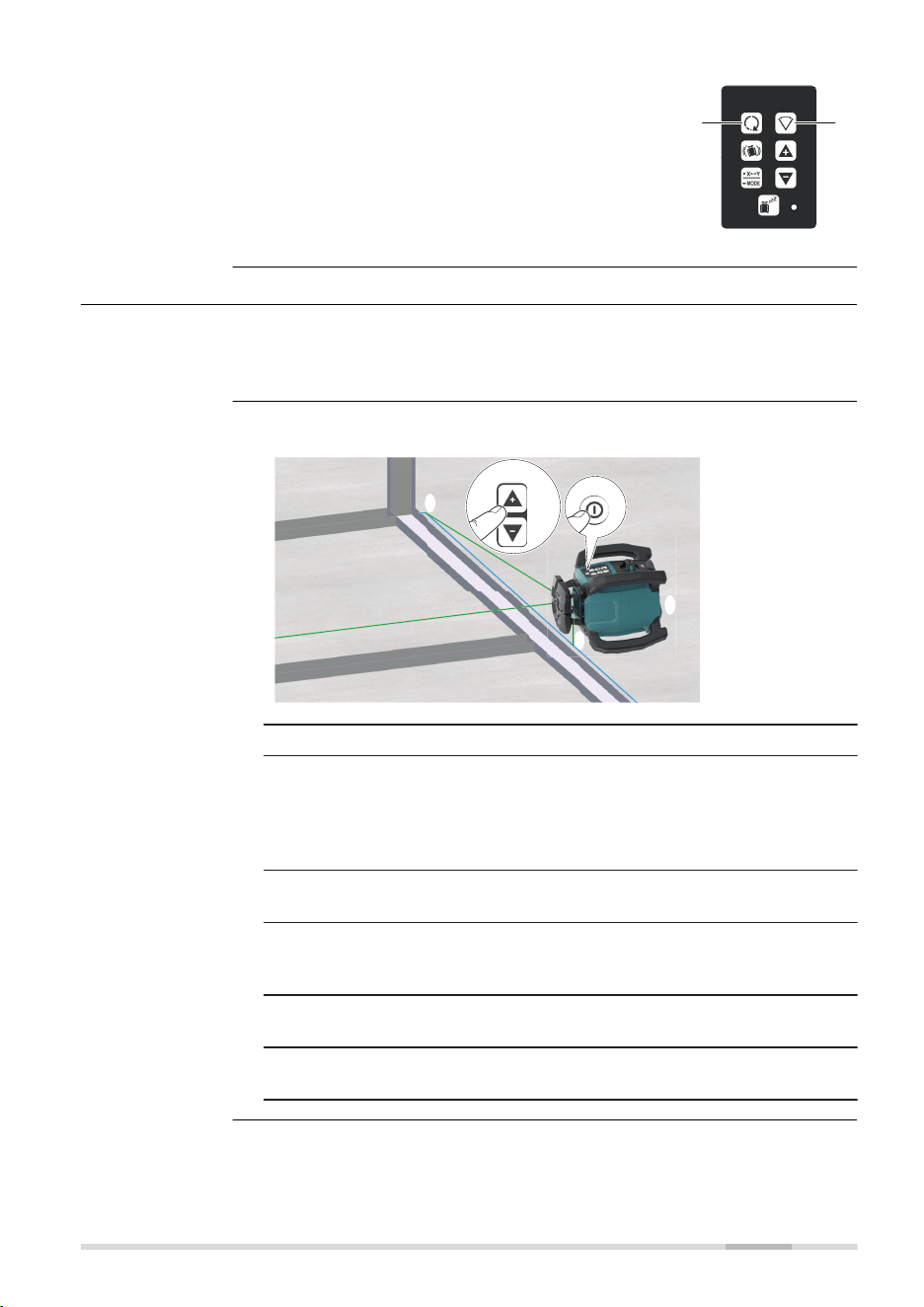
1. Turn off the power.
2. Press and hold both the Up and Down
arrow buttons.
3. Press the Power button. The active axis is
the X‑axis.
☞
The X-axis and the Y‑axis LEDs ash altern-
ately three times.
☞
The X-axis LED ashes three times, then
ashes slowly until level.
When the SKR001 is level, the X‑axis LED is
on, but does not ash.
☞
The Y-axis LED is off
1. Press the Up and Down arrow buttons to
increment the vertical position of the laser
beam.
☞
A ash of the X‑axis LED and an audio beep
indicate the change of an increment.
Entering adjust-
ment mode for
horizontal posi-
tion, step‑by‑step
Adjusting
the X‑axis,
step‑by‑step
48 Accuracy Adjustment
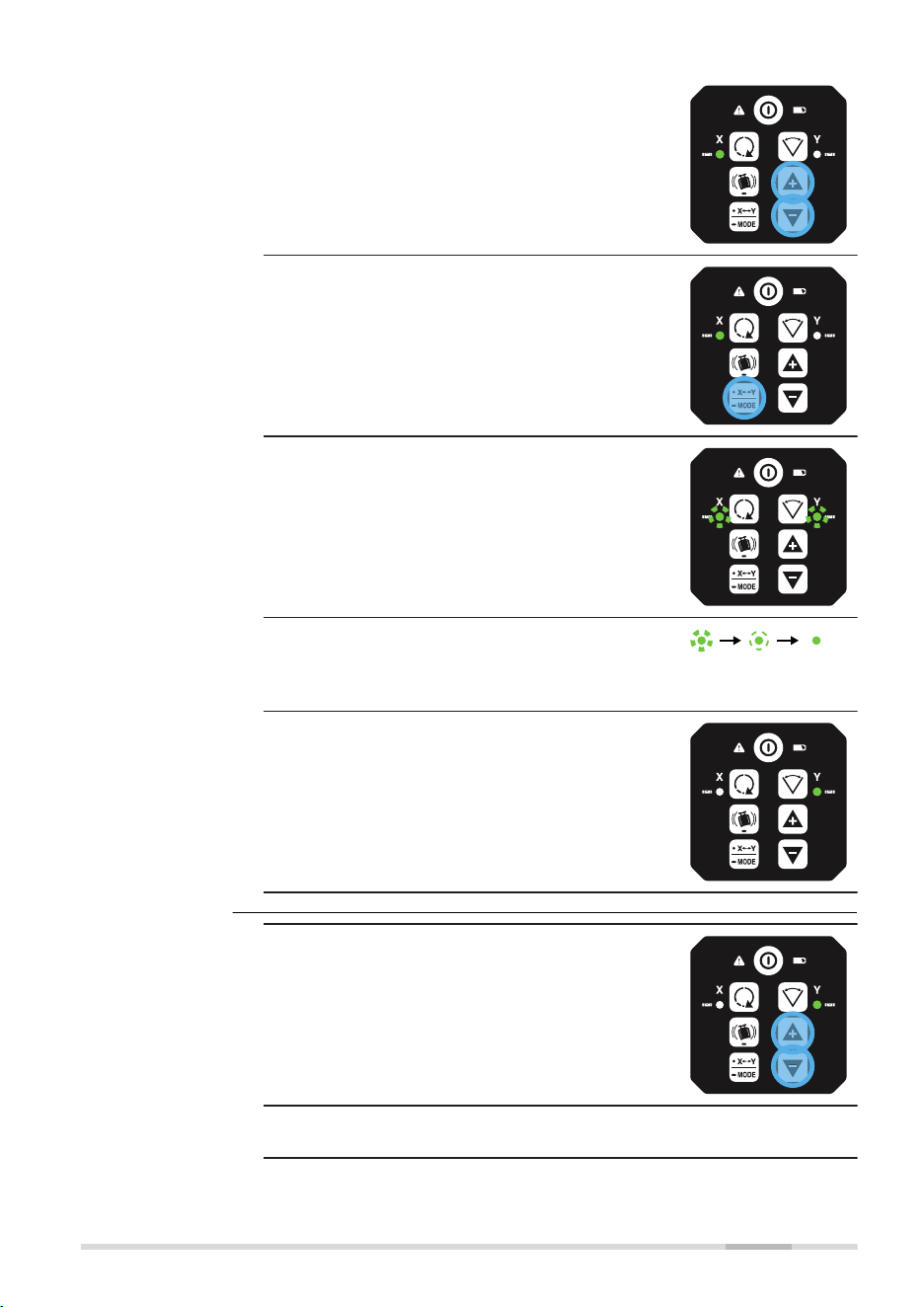
2. Continue to press the Up and Down arrow
buttons and monitor the spot until the
SKR001 is within its specied range.
☞
Five steps are equal to
15 arc seconds of change,
or approximately 2.2 mm at
30 m (3/32” at 100 ft).
3. Press the X/Y Mode button to change to
Y‑axis.
☞
The X-axis and the Y‑axis LEDs ash altern-
ately three times.
☞
The Y-axis LED ashes three times, then
ashes slowly until level.
When the SKR001 is level, the Y‑axis LED is
on, but does not ash.
☞
The X-axis LED is off.
1. Press the Up and Down arrow buttons to
increment the laser beam up and down.
☞
A ash of the Y‑axis LED and an audio beep
indicate the change of an increment.
Adjusting
the Y‑axis,
step‑by‑step
Accuracy Adjustment 49
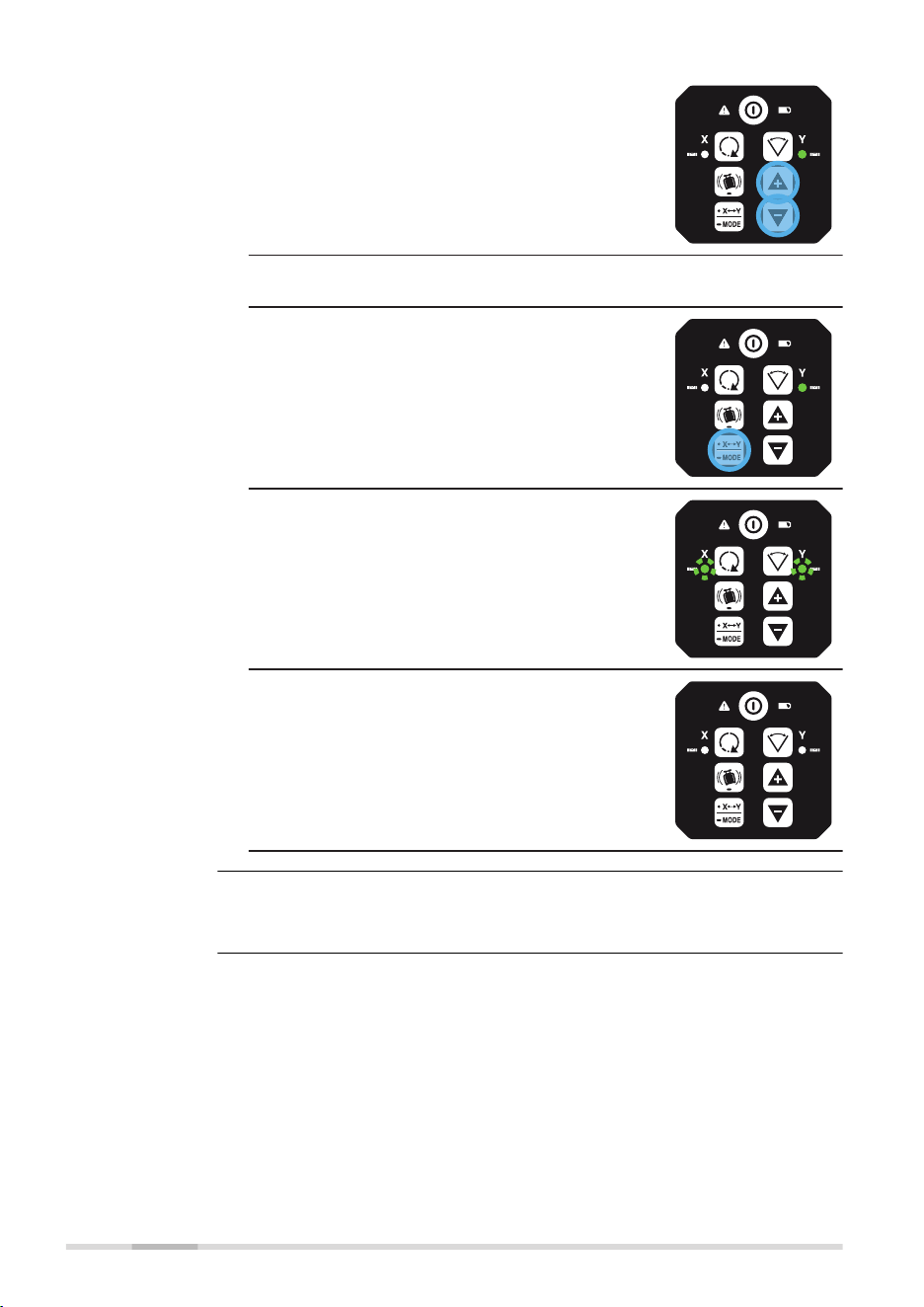
2. Continue to press the Up and Down arrow
buttons and monitor the spot until the
SKR001 is within its specied range.
☞
Five steps are equal to
15 arc seconds of change,
or approximately 2.2 mm at
30 m (3/32” at 100 ft).
☞
Press the X/Y Mode button to switch back
to the X‑axis if desired.
3. Press and hold the X/Y Mode button for
3 seconds to save and exit the Adjustment
Mode.
☞
The X‑axis LED and Y‑axis LED ash altern-
ately three times.
☞
The SKR001 shuts off.
Pressing the Power button at any time while in Adjustment Mode will exit the
mode without saving changes.
☞
50 Accuracy Adjustment
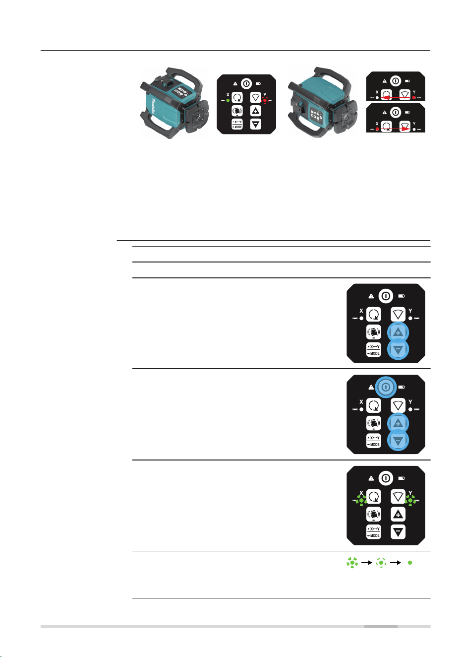
7.2.2 Laydown Position
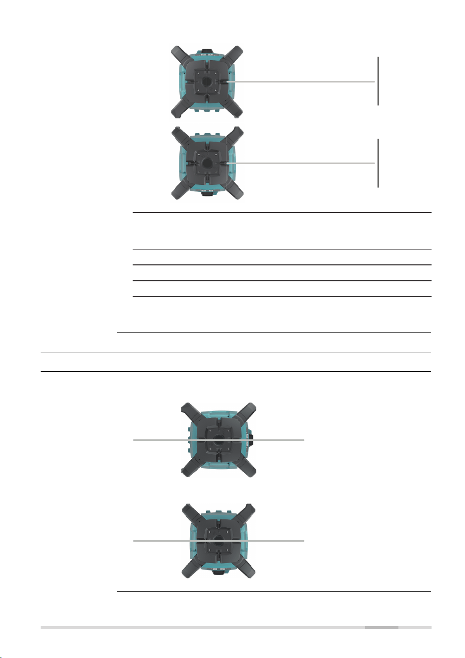
27976_001
When device is in normal laydown
position, keypad upwards:
•
X‑axis LED is solid green, if
levelled
•
Y‑axis LED ashes red, normal
laydown
27977_001
When device is in wrong laydown
position, keypad sidewards:
•
X‑axis LED and Y‑axis LED
ash at 2 Hz alternating to
alert failure
•
Additional beep alarm
This alert is same during normal
use but also during calibration.
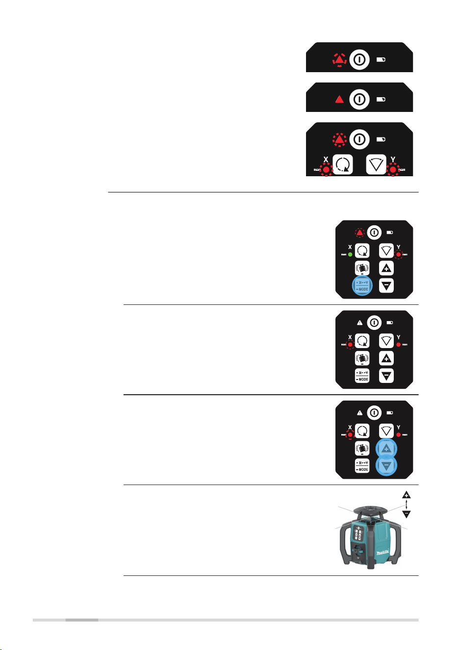
1. Turn off the power.
2. Place the SKR001 in the laydown position.
3. With power off, press and hold both the
Up and Down arrow buttons.
4. Press the Power button. The active axis is
the X‑axis.
☞
The X-axis and the Y‑axis LEDs ash altern-
ately three times.
☞
The X-axis LED ashes three times, then
ashes slowly until level.
When the SKR001 is level, the X‑axis LED is
on, but does not ash.
Laydown orienta-
tion detection
Entering adjust-
ment mode for
laydown position,
step‑by‑step
Accuracy Adjustment 51
☞
The Y-axis LED is off.
1. Press the Up and Down arrow buttons to
increment the vertical position of the laser
beam.
☞
A ash of the X‑axis LED and an audio beep
indicate the change of an increment.
2. Continue to press the Up and Down arrow
buttons and monitor the spot until the
SKR001 is within its specied range.
1. Press and hold the X/Y Mode button for
3 seconds to save and exit the Adjustment
Mode.
☞
The X‑axis LED and Y‑axis LED ash altern-
ately three times.
Adjusting the lay-
down position,
step‑by‑step
Exiting adjustment
mode
52 Accuracy Adjustment

☞
The SKR001 shuts off.
Pressing the Power button at any time while in Adjustment Mode will exit the
mode without saving changes.
☞
Accuracy Adjustment 53
8 Troubleshooting
Alert Symptom Possible causes and solutions
Low Battery
LED ashes
green.
The batteries are low. Replace the
Li‑Ion battery pack. Refer to 6 Bat-
teries.
!
5 Hz
Elevation
(H.I.Alert)
Alert LED, red -
fast ashing,
2 Hz and X‑axis
LED and Y‑axis
LED with a beep
alarm.
The SKR001 has been bumped or
tripod was moved. Turn off SKR001
to stop alert check the height of
the laser before beginning to work
again. Allow SKR001 to relevel and
check the height of the laser. After
2 minutes in the alert condition,
the unit will shut off automatically.
!
or
!
Servo Limit
Alert
Alert LED, red -
fast ashing,
2 Hz and either
X‑axis LED or
Y‑axis LED,
depending on
the axis which is
at limit.
The SKR001 is tipped too far to
reach a level position. Relevel the
SKR001 within the 5 degree self-
levelling range. This alert is also
displayed any time the unit is
tipped more than 5° from level.
After 2 minutes in the alert condi-
tion, the unit will shut off automat-
ically.
!
Environment
Temperature
Alert
Alert LED, red -
fast ashing,
2 Hz
The SKR001 is in an environment
where it cannot operate without
damaging the laser diode. This
damage could be a result of
heat from direct sunlight. Shade
the SKR001 from the sun. After
2 minutes in the alert condition,
the unit shuts off automatically.
☞
In case temperature
reaches operating
temperature range
again, the alert stops.
Alert is initiated, if:
• Temperature is ≥ 55 °C
• Temperature is ≤ −15 °C
Alerts
54 Troubleshooting

Problem Possible
Cause(s)
Suggested Solutions
The SKR001 is
working, but not
self-levelling.
The SKR001 is in
Manual Mode.
The SKR001 must be in Auto-
matic Mode to self-level. Set
the SKR001 to Automatic
Mode by pressing the Auto-
matic/Manual Mode button.
-
In Automatic Mode the X-
axis LED and the Y-axis
LED ash green while lev-
elling.
-
In Manual Mode the X-
axis LED and/or the Y-
axis LED are red.
SKR001 does not
turn on.
The batteries are
low or dead.
Check the batteries and
change or charge the batter-
ies if necessary. If the problem
continues, return the SKR001
to an authorised service centre
for service.
The distance of
the laser is
reduced.
Dirt is reducing
the laser output.
Clean the windows of the
SKR001 and the receiver. If the
problem continues, return the
SKR001 to an authorised ser-
vice centre for service.
The laser receiver
is not working
properly.
The SKR001 is not
rotating. It may
be levelling or in
Elevation Alert.
Check for proper operation of
the SKR001.
☞
Refer to the
receiver manual
for more inform-
ation.
The receiver is out
of usable range.
Move closer to the SKR001.
The batteries of
the receiver are
low.
Change the receiver batteries.
The SKR001 can-
not communicate
with the RC1
Remote Control.
The SKR001 and
the remote con-
trol have not been
paired and cannot
communicate with
each other.
Pair the SKR001 and the
remote control. Refer to 3.9.1
Pairing the SKR001 with the
RC1 Remote Control for more
information.
H.I.Alert function
is not working.
The H.I.Alert func-
tion is disabled.
The H.I.Alert function ist
enabled by long press of the
H.I.Alert button.
Refer to 3.8 Height of Instru-
ment Alert (H.I.Alert) function
for details.
Troubleshooting
Troubleshooting 55

Problem Possible
Cause(s)
Suggested Solutions
The SKR001 does
not turn on in
Automatic Mode.
The SKR001
is designed to
always turn on in
Automatic Mode
unless specically
disabled by the
user.
The Automatic Mode can
be enabled or disabled by
pressing the Automatic/Manual
Mode button.
The SKR001 is on,
but laser is not
rotating.
Rotation speed
may be set to
0 and/or dot is
not within visible
range.
Change rotation speed or turn
SKR001 off and on again.
56 Troubleshooting

9 Care and Transport
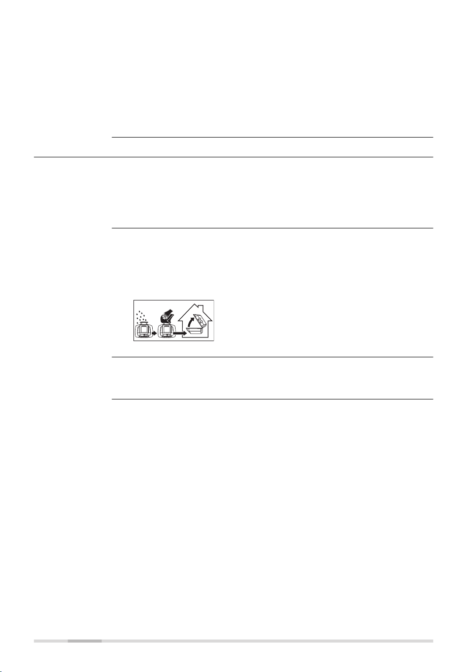
9.1 Transport
When transporting the equipment in the eld, always make sure that you
•
either carry the product in its original container,
•
or carry the tripod with its legs splayed across your shoulder, keeping
the attached product upright.
Never carry the product loose in a road vehicle, as it can be affected by
shock and vibration. Always carry the product in its container and secure it.
When transporting the product by rail, air or sea, always use the complete
original Makita packaging, container and cardboard box, or its equivalent, to
protect against shock and vibration.
When transporting or shipping batteries, the person responsible for the
product must ensure that the applicable national and international rules and
regulations are observed. Before transportation or shipping, contact your
local passenger or freight transport company.
Exposing the product to high mechanical forces, for example through fre-
quent transport or rough handling, or storing the product for a long time
may cause deviations and a decrease in the measurement accuracy. Period-
ically carry out test measurements and perform the eld adjustments indic-
ated in the User Manual before using the product.
9.2 Storage
Respect the temperature limits when storing the equipment, particularly in
summer if the equipment is inside a vehicle. Refer to 10 Technical Data for
information about temperature limits.
For Li-Ion and alkaline batteries
•
Refer to 10 Technical Data for information about storage temperature
range
•
Remove batteries from the product and the charger before storing
•
After storage recharge batteries before using
•
Protect batteries from damp and wetness. Wet or damp batteries must
be dried before storing or use
On-site transport
Transport in a road
vehicle
Shipping
Shipping, transport
of batteries
Field adjustment
Product
Li-Ion and alkaline
batteries
Care and Transport 57
For Li-Ion batteries
•
A storage temperature range of 0 °C to +30 °C / +32 °F to +86 °F in
a dry environment is recommended to minimize self-discharging of the
battery
•
At the recommended storage temperature range, batteries containing
a 40% to 50% charge can be stored for up to one year. After this
storage period the batteries must be recharged
9.3 Cleaning and Drying
•
Blow dust off lenses and prisms.
•
Never touch the glass with your ngers.
•
Use only a clean, soft, lint-free cloth for cleaning. If necessary, moisten
the cloth with water or pure alcohol. Do not use other liquids; these
may attack the polymer components.
Dry the product, the transport container, the foam inserts and the accessor-
ies at a temperature not greater than 40 °C/104 °F and clean them. Remove
the battery cover and dry the battery compartment. Do not repack until
everything is completely dry. Always close the transport container when
using in the eld.
Keep plugs clean and dry. Blow away any dirt lodged in the plugs of the
connecting cables.
Product and
accessories
Damp products
Cables and plugs
58 Care and Transport
10 Technical Data
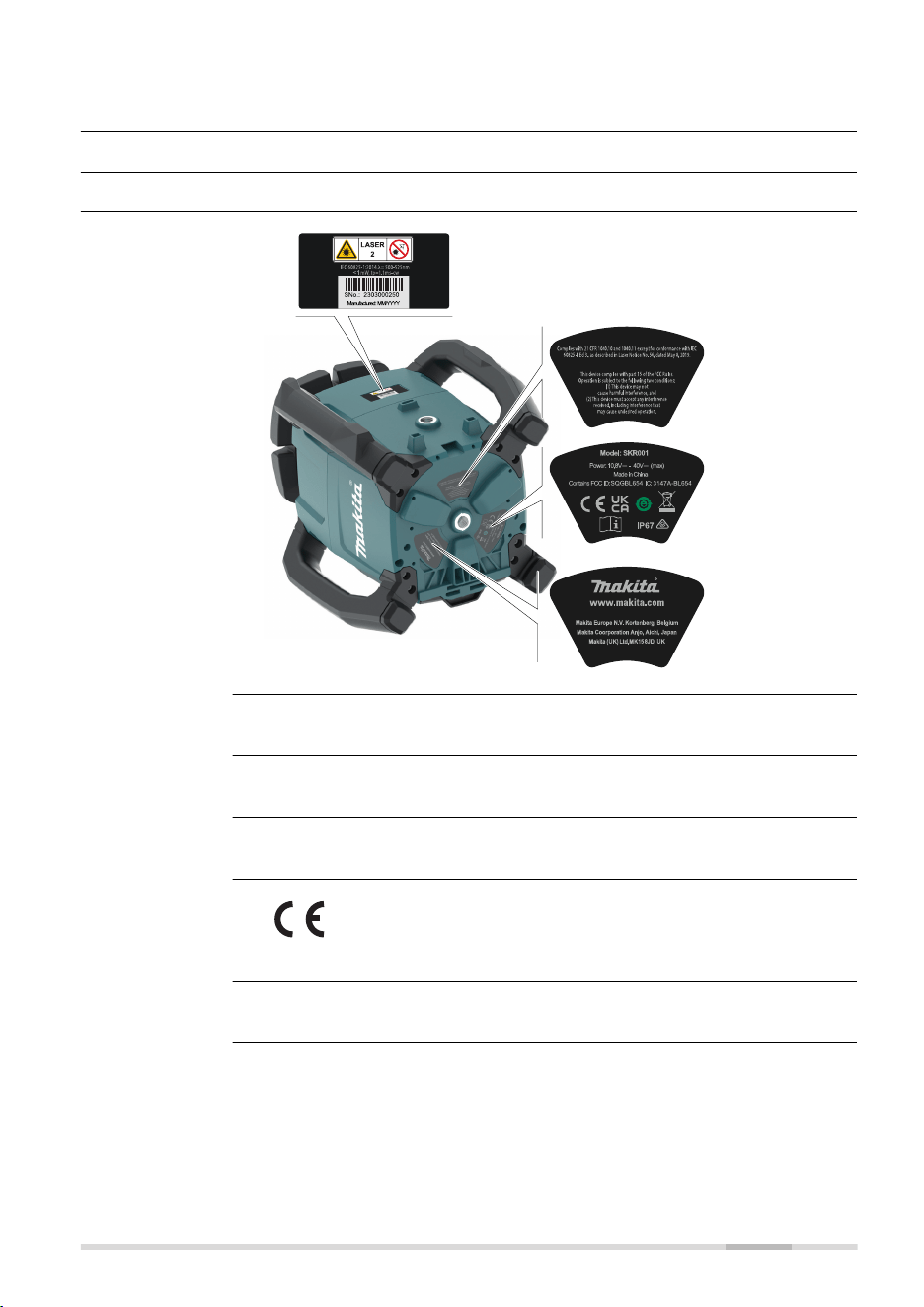
10.1 Conformity to National Regulations
10.1.1 SKR001
27418_001
SKR001: Chip antenna
2400 - 2483.5 MHz
< 100 mW (e. i. r. p.)
Hereby, Makita declares that the radio equipment type
SKR001 is in compliance with Directive 2014/53/EU and other
applicable European Directives.
FCC Part 15
This equipment has been tested and found to comply with the limits for a
Class B digital device, pursuant to part 15 of the FCC Rules.
These limits are designed to provide reasonable protection against harmful
interference in a residential installation.
Labelling SKR001
Antenna
Frequency band
Output power
EU
USA
Technical Data 59

This equipment generates, uses, and can radiate radio frequency energy and,
if not installed and used in accordance with the instructions, it may cause
harmful interference to radio communications.
However, there is no guarantee that interference does not occur in a partic-
ular installation.
If this equipment does cause harmful interference to radio or television
reception, which can be determined by turning the equipment off and on,
the user is encouraged to try to correct the interference by one or more of
the following measures:
•
Reorient or relocate the receiving antenna.
•
Increase the separation between the equipment and the receiver.
•
Connect the equipment into an outlet on a circuit different from that
to which the receiver is connected.
•
Consult the dealer or an experienced radio/TV technician for help.
Changes or modications not expressly approved by Makita for compliance
could void the user's authority to operate the equipment.
CAN ICES-003 B/NMB-003 B
Canada Compliance Statement
This device contains licence-exempt transmitter(s)/receiver(s) that com-
ply with Innovation, Science and Economic Development Canada’s licence-
exempt RSS(s). Operation is subject to the following two conditions:
1.
This device may not cause interference
2.
This device must accept any interference, including interference
that may cause undesired operation of the device
Canada Déclaration de Conformité
L’émetteur/récepteur exempt de licence contenu dans le présent appar-
eil est conforme aux CNR d’Innovation, Sciences et Développement
économique Canada applicables aux appareils radio exempts de licence.
L’exploitation est autorisée aux deux conditions suivantes:
1.
L’appareil ne doit pas produire de brouillage
2.
L’appareil doit accepter tout brouillage radioélectrique subi, même
si le brouillage est susceptible d’en compromettre le fonction-
nement du dispositif
The conformity for countries with other national regulations has to be
approved prior to use and operation.
Canada
Others
60 Technical Data
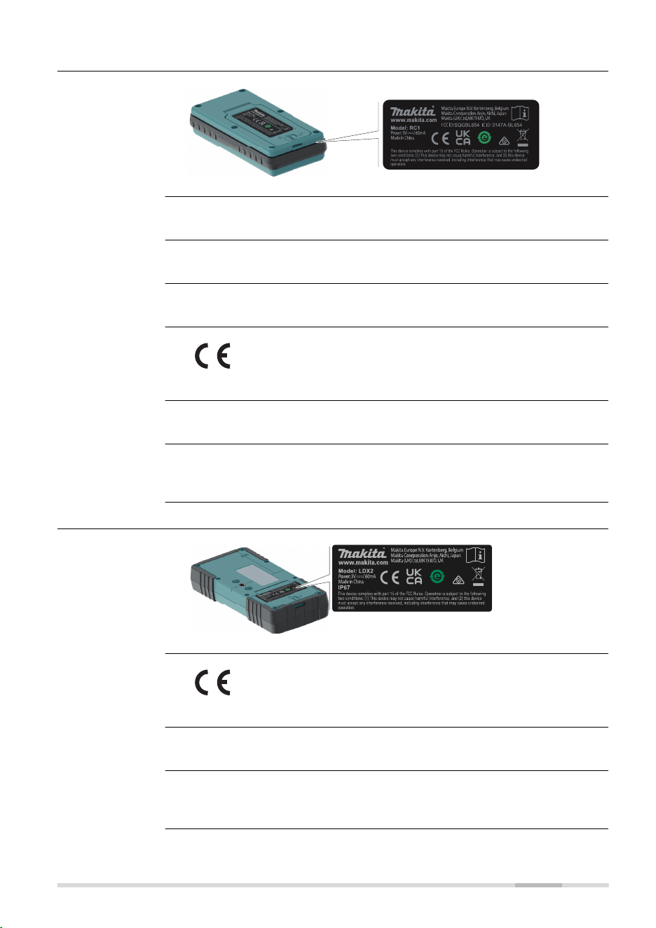
10.1.2 RC1 Remote Control
IP65
27420_001
RC1: Chip antenna
2400 - 2483.5 MHz
< 100 mW (e. i. r. p.)
Hereby, Makita declares that the radio equipment type RC1 is
in compliance with Directive 2014/53/EU and other applicable
European Directives.
FCC Part 15
The conformity for countries with other national regulations has to be
approved prior to use and operation.
10.1.3 LDX2 Digital Receiver
27419_001
Hereby, Makita declares that the radio equipment type LDX2 is
in compliance with Directive 2014/53/EU and other applicable
European Directives.
FCC Part 15
The conformity for countries with other national regulations has to be
approved prior to use and operation.
Labelling RC1
Antenna
Frequency band
Output power
EU
USA
Others
Labelling LDX2
EU
USA
Others
Technical Data 61
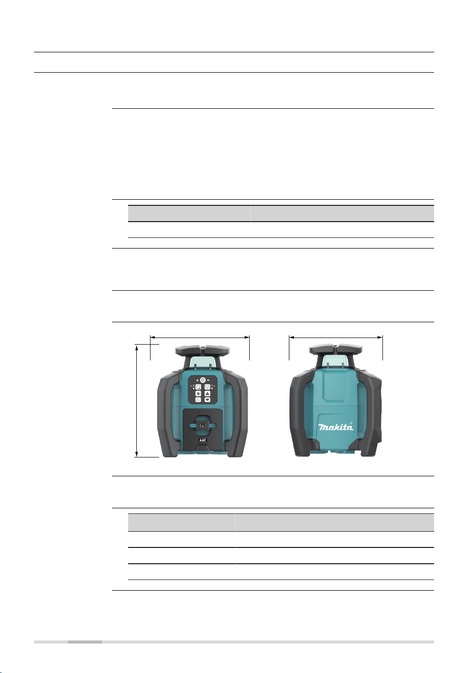
10.2 General Technical Data of the Product
10.2.1 SKR001
Radius: 400 m/1300 ft
Horizontal
±0.5 mm/10 m
Vertical
±0.75 mm/10 m
Severe temperature uctuations, humidity, impacts, and falls can affect
accuracy. Check accuracy before making important measurements.
Refer to 7.1 Checking the Level Accuracy for details.
Type Value
Self-levelling range ±5°
Rotation speed: 0/150/300/600 rpm
0/2.5/5/10 rps
Scanning modes: 30°/20°/10°
27458_001
309 mm (12.2")
250 mm (9.8") 250 mm (9.8")
SKR001 weight without battery: 4.0 kg/8.8 lbs.
Type
Operating times
1)
for SKR001 at 20 °C
BL1040B 55 h
BL1860B 135 h
BL4040 160 h
Operating range
Self-levelling
accuracy
Self-levelling range
Rotation speed
Scanning modes
Laser dimensions
Weight
Battery cartridge
1)
Operating times are dependent upon environmental conditions.
62 Technical Data
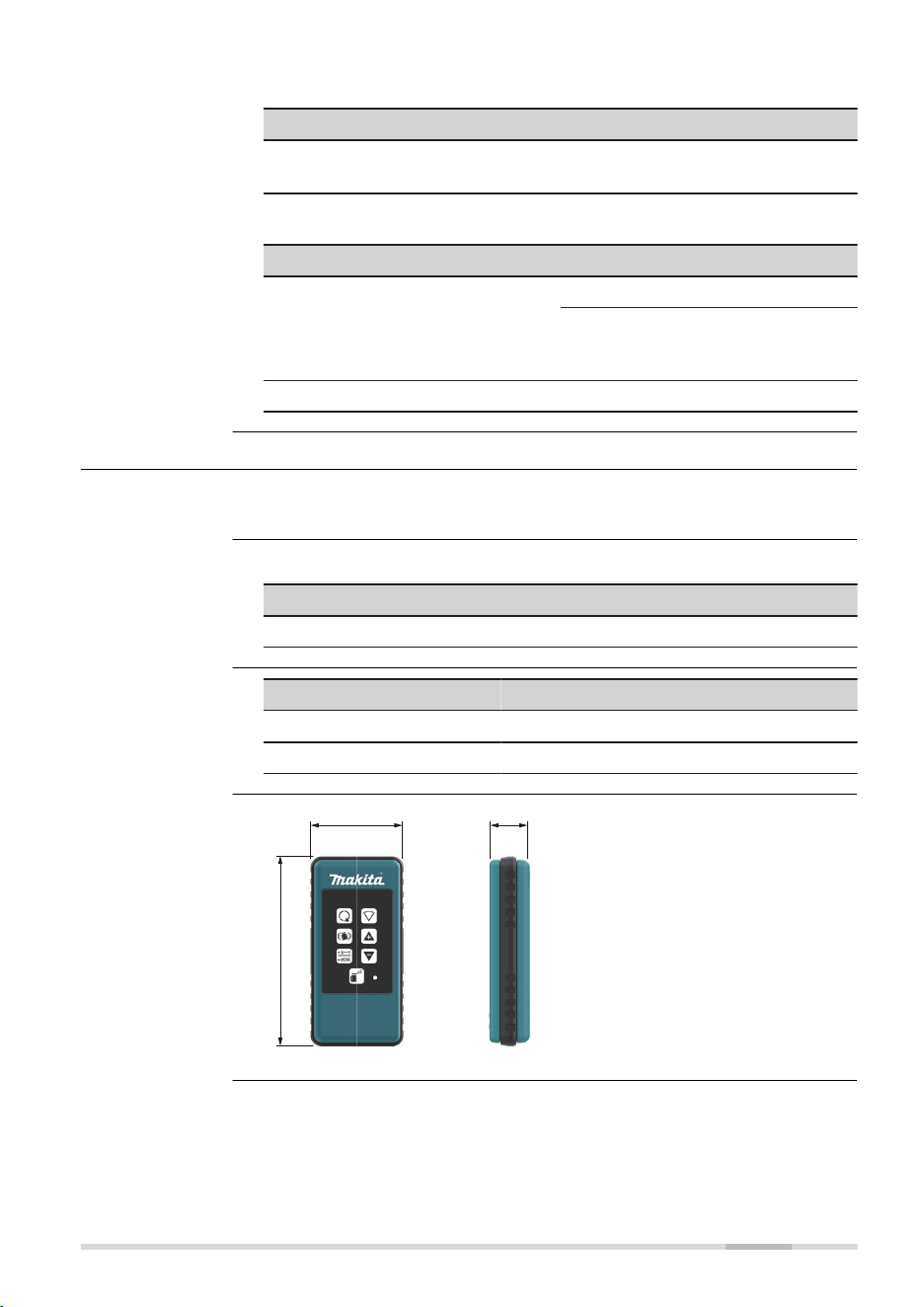
Temperature
Operating temperature Storage temperature
−10 °C to +50 °C
(14 °F to +122 °F)
−20 °C to +70 °C
(−4 °F to +158 °F)
Protection against water, dust and sand
Type Protection
SKR001
IP67 (IEC 60529)
Dust tight
Protected against continuous
immersion in water.
Battery compartment IP66
10.2.2 RC1 Remote Control
Radius: 100 m/328 ft
Protection against water, dust and sand
Protection
IP65 (IEC 60529)
Type Value
Batteries
2 × 1.5 V AA
Battery life, typical usage 70 hours
27459_001
122 mm (4.8")
59 mm (2.32") 25.8 mm (1.02")
Environmental
specications
Operating range
Environmental
specications
Batteries
Remote control
dimensions
Technical Data 63

10.2.3 LDX2 Digital Receiver
Working diameter (laser
dependent)
800 m/2625 ft
Digital readout up to 200 m/656 ft
Detection height 120 mm/5 in
Numeric readout height 90 mm/3.5 in
Detectable spectrum Green laser: 500-570 nm
Red laser: 600-800 nm
Detection sensitivity
Very ne ±0.5 mm/±0.02 in
Fine ±1.0 mm/±0.04 in
Medium ±2.0 mm/±0.08 in
Coarse ±3.0 mm/±0.12 in
Very coarse ±5.0 mm/±0.20 in
Audio volumes 105 dBA/95 dBA/65dBA/Off
Automatic shut off 10 minutes
Digital readout - units mm, cm, in, in (fractions), ft
Arrow display - channels 15 channels
Anti-strobe protection Yes
Memory, last beam strike Yes
Beam nding (double beep) Yes
Laser low battery indicator Yes
Batteries
2 × 1.5 V AA
Battery life, typical usage 50 hours
Temperature
Operating temperature Storage temperature
−20 °C to +50 °C
−4 °F to +122 °F
−40 °C to +70 °C
−40 °F to +158 °F
Protection against water, dust and sand
Type Protection
LDX2 IP67 (IEC 60529)
Dust tight
Protected against continuous
immersion in water.
Battery compartment IP65
Technical data
Environmental
specications
64 Technical Data
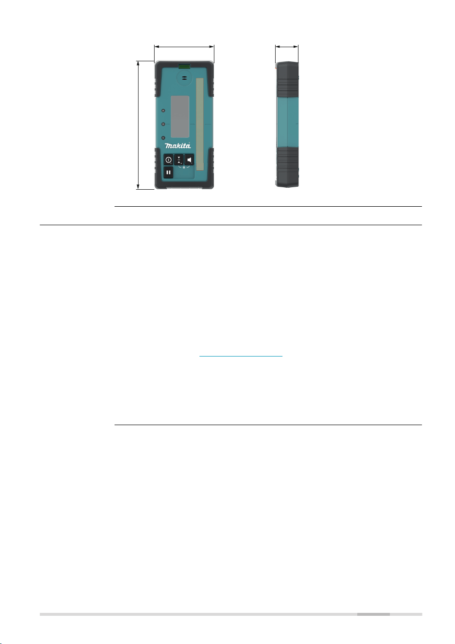
27972_001
173 mm (6.8")
76 mm (3.0") 29 mm (1.1")
10.3 Dangerous Goods Regulations
Many products of Makita are powered by Lithium batteries.
Lithium batteries can be dangerous under certain conditions and can pose
a safety hazard. In certain conditions, Lithium batteries can overheat and
ignite.
☞
When carrying or shipping your Makita product with Lithium bat-
teries onboard a commercial aircraft, you must do so in accord-
ance with the IATA Dangerous Goods Regulations.
☞
There are guidelines on How to carry and How to ship
products with Lithium batteries. Before any transportation of a
Makita product, we ask you to consult the guidelines on the web
page (IATA Lithium Batteries) to ensure that you are in accord-
ance with the IATA Dangerous Goods Regulations and that the
Makita products can be transported correctly.
☞
Damaged or defective batteries are prohibited from being car-
ried or transported onboard any aircraft. Therefore, ensure that
the condition of any battery is safe for transportation.
Dimensions
Dangerous Goods
Regulations
Technical Data 65
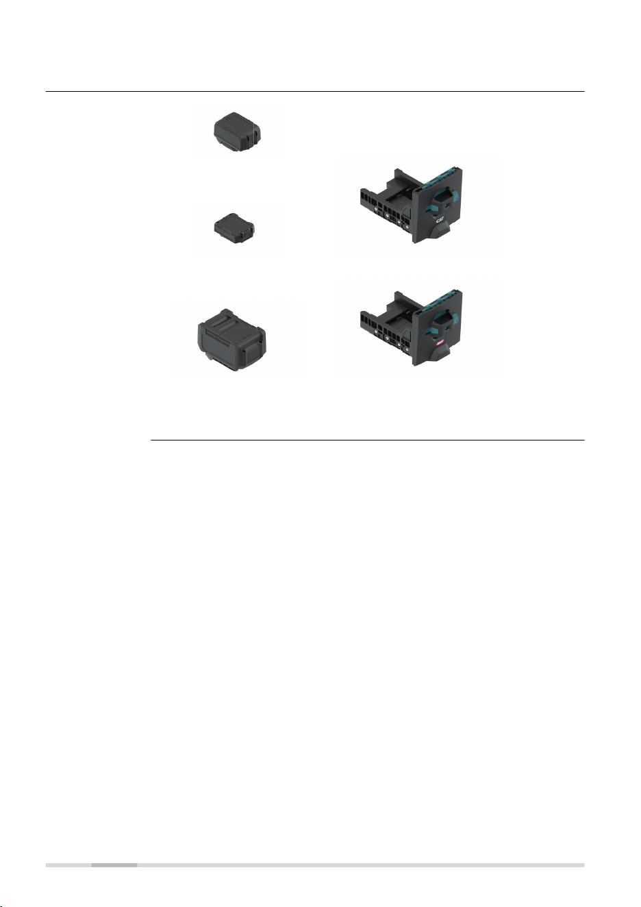
11 Accessories
27460_002
LXT Batteries
CXT Batteries Battery tray for CXT
XGT Batteries
Capacity: 4 Ah or less
Battery tray for XGT
Accessories for
power supply
66 Accessories


993612-1.1.0en
Original text (993612-1.1.0en)
Makita Corporation
3-11-8, Sumiyoshi-cho,
Anjo,Aichi 446-8502 Japan
Makita Europe N. V.
Jan-Baptist Vinkstraat 2
3070 Kortenberg, Belgium
Makita UK Ltd
MK15 8JD,United Kingdom
www.makita.com