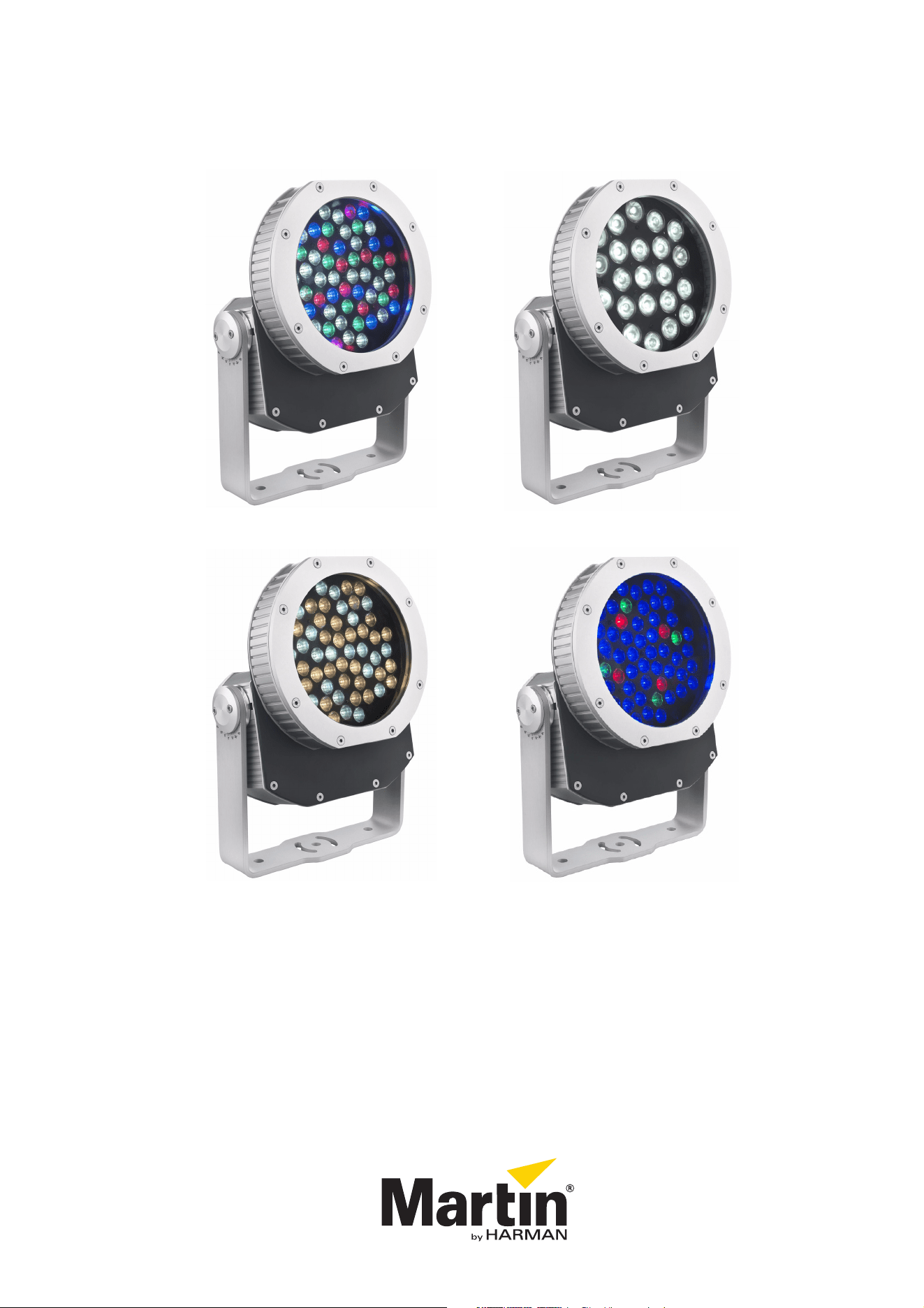
Exterior 400 Exterior 410
Exterior 420 Exterior 430
user manual
Exterior 400™ Range
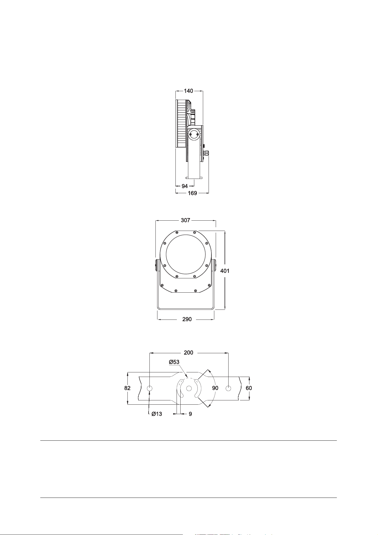
Dimensions
All dimensions are in millimeters
©2010-2015 Martin Professional ApS. Information subject to change without notice. Martin Professional ApS and all affiliated
companies disclaim liability for any injury, damage, direct or indirect loss, consequential or economic loss or any other loss
occasioned by the use of, inability to use or reliance on the information contained in this manual. The Martin logo, the Martin name
and all other trademarks in this document pertaining to services or products by Martin Professional ApS or its affiliates and
subsidiaries are trademarks owned or licensed by Martin Professional ApS or its affiliates or subsidiaries. The use of certain patents
in Martin Exterior 400 Range products is licensed by Color Kinetics, Inc. (see details printed on product).
P/N 35000237, Rev. F
Safety Information
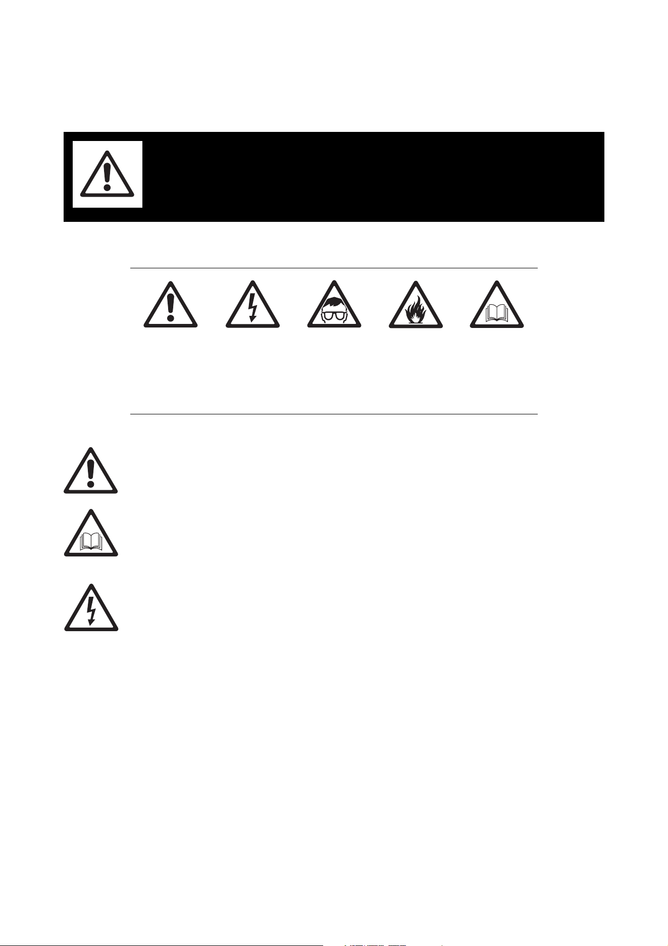
The following symbols are used to identify important safety information on the product and in this manual:
This product is for professional use only. It is not for household use.
This product presents risks of severe injury or death due to fire hazards, electric shock and falls.
Read this manual before installing, powering or servicing the fixture, follow the safety precautions listed
below and observe all warnings in this manual and printed on the fixture. Install and operate the fixture only
as described in this manual and in accordance with local laws and regulations. Refer any operation not
described in this manual to a qualified technician.
If you have questions about how to operate the fixture safely, please contact your Martin supplier or call the
Martin 24-hour service hotline on +45 8740 0000, or in the USA on 1-888-tech-180.
PROTECTION FROM ELECTRIC SHOCK
• Shut down power to the entire installation at the main power distribution board and lock out power (by
removing the fuse for example) before carrying out any installation or maintenance work.
• Disconnect the fixture from AC power before removing or installing any cover or part and when not in use.
• Connect the fixture electrically to ground (earth).
• Use only a source of AC power that complies with local building and electrical codes and has both
overload and ground-fault (earth-fault) protection.
• Connect the fixture to AC power either using either the supplied power cable or a listed 3-conductor
Hypalon or neoprene rubber-jacket cable rated to 90° C (194° F) minimum and with conductor size 1.5
mm
2
or 16 AWG minimum.
• Before using the fixture, check that all power distribution equipment and cables are in perfect condition,
are rated for the current requirements of all connected devices, are protected to IP67 or higher and are of
suitable type for the location (including water, pollution, temperature and UV resistance).
• Isolate the fixture from power immediately if any cable, seal, cover or other component is damaged,
cracked or deformed. Do not reapply power until repairs have been completed.
• Do not expose any part of the fixture to a high-pressure water jet.
• Do not immerse the fixture in water or any other fluid, or install it in a location where flooding may occur.
• Refer any service operation not described in this manual to an authorized Martin Service partner.
WARNING!
Read the safety precautions in this section before
installing, powering, operating or servicing this
product.
WARNING!
Safety hazard.
Risk of severe
injury or death.
WARNING!
Hazardous
voltage. Risk of
lethal or severe
electric shock.
WARNING!
LED light
emission. Risk
Group 3
according to IEC
62471.
WARNING!
Fire hazard.
WARNING!
Refer to user
manual.
PROTECTION FROM BURNS AND FIRE
• Do not operate the fixture if the ambient temperature (Ta) exceeds 45° C (113° F).
• The exterior of the fixture becomes hot, up to 90° C (194° F) during normal operation. Ensure that
accidental physical contact with a hot fixture is impossible.
• Allow the fixture to cool for 20 minutes before servicing.
• Do not illuminate surfaces less than 0.1 m (4 in.) from the front surface of the fixture.
• Keep flammable materials well away from the fixture.
• Do not modify the fixture in any way not described in this manual or install other than genuine Martin
parts. Do not stick filters, masks or other materials directly onto LEDs. Use only Martin approved
accessories to mask or modify the light beam.
• Do not attempt to bypass thermostatic switches or fuses. Replace defective fuses with ones of the
specified type and rating only.
• Install the fixture outdoors or in a well-ventilated area only. Provide a minimum clearance of 150 mm (6
in.) and ensure unrestricted airflow around the fixture.
• Provide a minimum center-to-center distance of 550 mm (21.7 in.) between Exterior 400 Range fixtures.
PROTECTION FROM INJURY
• Classified as LED Risk Group 3 product with all LEDs at full intensity, 1/10 peak beam angle 6°, according
to IEC 62471. Do not look at LEDs from a distance of less than 8.3 m (27.3 ft.) from the front surface of
the fixture without suitable protective eyewear. At less than this distance, the LED emission can cause
eye injury or irritation. At distances of 8.3 m (27.3 ft.) and above, light output is harmless to the naked eye.
• Do not look at LEDs with magnifiers or similar optical instruments that may concentrate the light output.
• Ensure that all external covers, components and installation fittings are securely fastened.
• Block access below the work area and work from a stable platform whenever installing, servicing or
moving the fixture.
• Ensure that all supporting structures, surfaces, fasteners and lifting equipment can bear the weight of all
the devices they are intended to support plus an adequate safety margin, and that they conform to local
building and safety regulations.
• Use a sufficient number of fasteners with sufficient corrosion resistance, dimensions and strength to
mount the fixture safely. Any nuts used must be self-locking. Washers must be installed directly under the
fasteners’ heads when anchoring the yoke base to the installation surface.
Disposing of this product
Martin™ products are supplied in compliance with Directive 2012/19/EC of the European Parliament and of
the Council of the European Union on WEEE (Waste Electrical and Electronic Equipment), where
applicable.
Help preserve the environment! Ensure that this product is recycled at the end of its life. Your supplier can
give details of local arrangements for the disposal of Martin products.

Contents
Dimensions . . . . . . . . . . . . . . . . . . . . . . . . . . . . . . . . . . . . . . . . . . . . . . . . . . . . . . . . . . . . . . . . . . . . . . . . 2
Safety Information. . . . . . . . . . . . . . . . . . . . . . . . . . . . . . . . . . . . . . . . . . . . . . . . . . . . . . . . . . . . . . . . . . 3
Introduction . . . . . . . . . . . . . . . . . . . . . . . . . . . . . . . . . . . . . . . . . . . . . . . . . . . . . . . . . . . . . . . . . . . . . . . . 6
Unpacking . . . . . . . . . . . . . . . . . . . . . . . . . . . . . . . . . . . . . . . . . . . . . . . . . . . . . . . . . . . . . . . . . . . . . . . . 6
Using for the first time . . . . . . . . . . . . . . . . . . . . . . . . . . . . . . . . . . . . . . . . . . . . . . . . . . . . . . . . . . . . . . . 6
Managing humidity . . . . . . . . . . . . . . . . . . . . . . . . . . . . . . . . . . . . . . . . . . . . . . . . . . . . . . . . . . . . . . . . . 7
Physical installation . . . . . . . . . . . . . . . . . . . . . . . . . . . . . . . . . . . . . . . . . . . . . . . . . . . . . . . . . . . . . . . . 8
Location and orientation . . . . . . . . . . . . . . . . . . . . . . . . . . . . . . . . . . . . . . . . . . . . . . . . . . . . . . . . . . . . . 8
Extended mounting yoke . . . . . . . . . . . . . . . . . . . . . . . . . . . . . . . . . . . . . . . . . . . . . . . . . . . . . . . . . . . . . 8
Mounting fasteners . . . . . . . . . . . . . . . . . . . . . . . . . . . . . . . . . . . . . . . . . . . . . . . . . . . . . . . . . . . . . . . . 10
Tilt adjustment . . . . . . . . . . . . . . . . . . . . . . . . . . . . . . . . . . . . . . . . . . . . . . . . . . . . . . . . . . . . . . . . . . . . 10
Power and DMX data cable layout . . . . . . . . . . . . . . . . . . . . . . . . . . . . . . . . . . . . . . . . . . . . . . . . . . . . 11
AC power . . . . . . . . . . . . . . . . . . . . . . . . . . . . . . . . . . . . . . . . . . . . . . . . . . . . . . . . . . . . . . . . . . . . . . . . . 12
Connecting to power . . . . . . . . . . . . . . . . . . . . . . . . . . . . . . . . . . . . . . . . . . . . . . . . . . . . . . . . . . . . . . . 12
Replacing the power cable . . . . . . . . . . . . . . . . . . . . . . . . . . . . . . . . . . . . . . . . . . . . . . . . . . . . . . . . . . 13
Control data link. . . . . . . . . . . . . . . . . . . . . . . . . . . . . . . . . . . . . . . . . . . . . . . . . . . . . . . . . . . . . . . . . . . 15
Connecting the data link . . . . . . . . . . . . . . . . . . . . . . . . . . . . . . . . . . . . . . . . . . . . . . . . . . . . . . . . . . . . 16
Fixture setup . . . . . . . . . . . . . . . . . . . . . . . . . . . . . . . . . . . . . . . . . . . . . . . . . . . . . . . . . . . . . . . . . . . . . . 17
Connecting a PC with MUM. . . . . . . . . . . . . . . . . . . . . . . . . . . . . . . . . . . . . . . . . . . . . . . . . . . . . . . . . . 17
Configuring a fixture with MUM . . . . . . . . . . . . . . . . . . . . . . . . . . . . . . . . . . . . . . . . . . . . . . . . . . . . . . . 18
Operation . . . . . . . . . . . . . . . . . . . . . . . . . . . . . . . . . . . . . . . . . . . . . . . . . . . . . . . . . . . . . . . . . . . . . . . . . 21
DMX control . . . . . . . . . . . . . . . . . . . . . . . . . . . . . . . . . . . . . . . . . . . . . . . . . . . . . . . . . . . . . . . . . . . . . . 21
Stand-alone operation . . . . . . . . . . . . . . . . . . . . . . . . . . . . . . . . . . . . . . . . . . . . . . . . . . . . . . . . . . . . . . 21
Service and maintenance. . . . . . . . . . . . . . . . . . . . . . . . . . . . . . . . . . . . . . . . . . . . . . . . . . . . . . . . . . 27
Cleaning. . . . . . . . . . . . . . . . . . . . . . . . . . . . . . . . . . . . . . . . . . . . . . . . . . . . . . . . . . . . . . . . . . . . . . . . . 27
Installing and removing a diffuser filter . . . . . . . . . . . . . . . . . . . . . . . . . . . . . . . . . . . . . . . . . . . . . . . . . 28
Fuse replacement . . . . . . . . . . . . . . . . . . . . . . . . . . . . . . . . . . . . . . . . . . . . . . . . . . . . . . . . . . . . . . . . . 29
Fixture readouts in MUM . . . . . . . . . . . . . . . . . . . . . . . . . . . . . . . . . . . . . . . . . . . . . . . . . . . . . . . . . . . . 29
Software installation. . . . . . . . . . . . . . . . . . . . . . . . . . . . . . . . . . . . . . . . . . . . . . . . . . . . . . . . . . . . . . . . 30
Status indicators . . . . . . . . . . . . . . . . . . . . . . . . . . . . . . . . . . . . . . . . . . . . . . . . . . . . . . . . . . . . . . . . . . 31
DMX protocols . . . . . . . . . . . . . . . . . . . . . . . . . . . . . . . . . . . . . . . . . . . . . . . . . . . . . . . . . . . . . . . . . . . . 32
Exterior 400, Exterior 410 . . . . . . . . . . . . . . . . . . . . . . . . . . . . . . . . . . . . . . . . . . . . . . . . . . . . . . . . . . . 32
Exterior 420 . . . . . . . . . . . . . . . . . . . . . . . . . . . . . . . . . . . . . . . . . . . . . . . . . . . . . . . . . . . . . . . . . . . . . . 33
Exterior 430 . . . . . . . . . . . . . . . . . . . . . . . . . . . . . . . . . . . . . . . . . . . . . . . . . . . . . . . . . . . . . . . . . . . . . . 34
Troubleshooting. . . . . . . . . . . . . . . . . . . . . . . . . . . . . . . . . . . . . . . . . . . . . . . . . . . . . . . . . . . . . . . . . . . 35
Specifications . . . . . . . . . . . . . . . . . . . . . . . . . . . . . . . . . . . . . . . . . . . . . . . . . . . . . . . . . . . . . . . . . . . . . 36

6 Exterior 400 Range user manual
Introduction
Thank you for selecting a product from the Exterior 400™ Range of compact IP65-rated LED-based
floodlights from Martin Professional™. The Exterior 400 Range includes the following models:
Exterior 400
• Optimized for long-throw applications in combination with very narrow beam angle optics
• 56 single-chip Cree XP-E LEDs
• RGBW (red, green, blue, white) and RGB color mixing, HSIC (hue, saturation, intensity, color
temperature) and HSI color management
Exterior 410
• Optimized for evenness of color mixing
• 22 multi-chip Cree MC-E LEDs
• RGBW and RGB color mixing, HSIC and HSI color management
Exterior 420
• Optimized for color temperature control
• Single-chip Cree XP-E warm white and cold white LEDs
Exterior 430
• Optimized for single-color, high-output applications
• Single-color, single-chip Cree XP-E LEDs
• Red, green, blue, warm white or cold white LEDs
• Color fine-tuning available on red, green and blue fixtures through use of auxiliary color LEDs
All Exterior 400 Range models feature:
• Diffuser filters for alternative beam angles
• Auto-sensing power supply unit with 100 - 240 V, 50/60 Hz operating range
• DMX 512A control (1 - 4 channels depending on fixture and control mode)
• Remote configuration and addressing over the DMX data link using Martin MUM™ software running on a
Windows PC and a USB/DMX hardware interface such as the Martin DABS1™.
For the latest light output measurements, firmware updates, documentation, product specifications and
other information about this and all Martin Professional™ products, please visit the Martin website at
http://www.martin.com
Comments or suggestions regarding this document may be e-mailed to service@martin.dk or posted to
Technical Documentation, Martin Professional A/S, Olof Palmes Allé 18, DK-8200 Aarhus N, Denmark.
Unpacking
The following items are included with the Exterior 400 Range:
• Adjustable mounting bracket
• Narrow, Medium and Wide diffuser filters (supplied separately)
• This user manual
Using for the first time
Before applying power to the fixture:
• Carefully review “Safety Information” on page 3.
• Check that the local AC power voltage is within the range listed on the fixture’s serial number label.
• Install the fixture as described in this manual

Managing humidity 7
Managing humidity
The fixtures in the Exterior 400 Range are IP65-rated and are designed to resist water and moisture in
environments with widely varying climate, temperature and humidity conditions. But if fixtures are not
managed correctly during installation and service, water and moisture can enter, leading to humidity and
condensation inside the fixtures. Follow the precautions in this chapter to avoid this problem.
General
• Carry out service during low-humidly weather conditions (or indoors if possible). Check that fixtures are
dry and free of moist air before closing them.
• Tighten cover screws exactly as directed in this manual and using a torque driver.
• Make sure that all threads are clean and dry. Do not apply lubricant to threads before assembly. While
lubricant may make disassembly easier during future service, it means that tightening screws to the
specified torque will apply excessive compression to seals. This may deform them and reduce their
effectiveness.
• Air, and even water, can be sucked along cables and into fixtures. A cracked or porous cable jacket can
allow water into the cable. Replace any cable that is not in perfect condition. Make sure that cables from
fixtures open into dry areas (e.g. junction boxes in dry locations).
• Do not clean fixtures with high-pressure water jets or immerse them.
Seals and sealing surfaces
The fixture must be sealed effectively. Covers have silicone seals that will withstand rain and water
splashing but will not withstand immersion or high-pressure water jets. Covers and seals must be reinstalled
carefully if they are removed.
• Invert the fixture if necessary to avoid water collecting in a pool around a seal (see “Avoiding water
pooling on the power box” on page 9).
• Make sure that seals and sealing surfaces are perfectly clean, dry and in perfect condition before
installing a cover. If you need to clean seals, use water and a soft cloth only. Replace any seal that shows
signs of aging, damage, cracking, stretching or deformation. Replacement seals are available from
Martin™.
• Reinstall seals in exactly their original position.
• Install seals so that they closely follow the profile of the metal parts they are installed on. When you run
your finger around the sealing surface after you have installed a cover, you should not be able to feel any
places where the seal sticks out or sinks into the gap between the sealing surfaces.
• If spacer rings are fitted on screws that hold sealing surfaces together, reinstall them in the same
positions when you reassemble products after service. Spacer rings ensure that the silicone seal around
them is compressed by exactly the right amount when bolts are tightened and minimize the risk of
deformation of components.
• Do not use liquid gasket or any other type of sealant on sealing surfaces or seals.
Anti-humidity valves
A valve with a Gore-tex membrane on the back of the fixture equalizes pressure by allowing air to pass
through it when the fixture heats up and cools down, but at the same time it acts as a barrier to water in
liquid form. The expulsion of warm air (with a slightly higher water vapor content) and intake of cool air (with
a slightly lower water vapor content) prevents humidity buildup over time, provided that the valve works
correctly and the fixture is correctly sealed.
Valves become blocked over time as the micropores in the membrane fill with particles, If a valve becomes
blocked by dirt or water, excess pressure can damage seals or cause air and even water to be sucked into
the fixture along cables. Valves cannot be cleaned and must be replaced if not in perfect condition.
Valves have a limited service life, but replacement intervals depend on the amount of airborne dirt and dust
in the installation location. Replacement valves are available from Martin™.
• Do not allow water to collect on or near valves. Do not install a fixture with the valve membrane horizontal
so that water can pool on it.
• Replace a valve with a new item if it shows any signs of contamination or is not in perfect condition.
• Replace valves after an extended period of use. Intervals for valve replacement depend on the installation
environment.
8 Exterior 400 Range user manual
Physical installation
Warning! Read "Safety Information" on page 3 before installing the Exterior 400 Range.
Warning! The safety and suitability of lifting equipment, installation location, anchoring method,
mounting hardware and electrical installation is the responsibility of the installer. All local safety
regulations and legal requirements must be observed when installing and connecting the Exterior
400 Range. Installation must be carried out by qualified professionals only.
Contact your Martin supplier for assistance if you have any questions about how to install this
product safely.
Location and orientation
Warning! The Exterior 400 Range mounting yoke base must be securely anchored to a suitable flat
surface at any angle, pedestal or other suitable support. Ensure that the supporting structure can
bear the weight of all installed devices plus an adequate safety margin.
Important! Make sure that there will be at least 0.1 m (4 in.) of free space and unrestricted airflow around
the fixture.
Allow for service access to the front and rear of the fixture.
An Exterior 400 Range fixture can be installed outdoors. It has an IP rating of 65 and is designed to
withstand rain and other low-pressure water projections but:
• Do not expose it to high-pressure water jets from any direction
• Do not immerse it in water (or any other fluid)
• Do not install it in a location where flooding may occur.
Ensure sufficient drainage to cope with the heaviest rainfall. Make sure that water can drain away from the
installation area at least as fast as it can enter it.
Exterior 400 Range fixtures require free and unobstructed airflow around them to ensure adequate cooling:
• Do not bury the fixture or locate it in an unventilated space
• Allow at least 0.1 m (4 in.) free space around the fixture
Install the fixture at least 0.5 m (20 in.)away from any combustible materials (wood, paper, etc.) and well
away from any flammable materials.
The aluminum housing reaches temperatures up to 90° C (194° F). Restrict public access or locate the
fixture so that it cannot accidentally be touched.
Extended mounting yoke
An extended mounting yoke is available as an accessory for the
Exterior 400 Range by ordering P/N 21080030 (see Figure 1,
Exterior 400 Image Projector illustrated). This extra-long bracket
gives additional installation options. It offers a practical solution if
you cannot install a fixture at a specific tilt angle using the standard
yoke.
Figure 1: Extended mounting
yoke
Physical installation 9
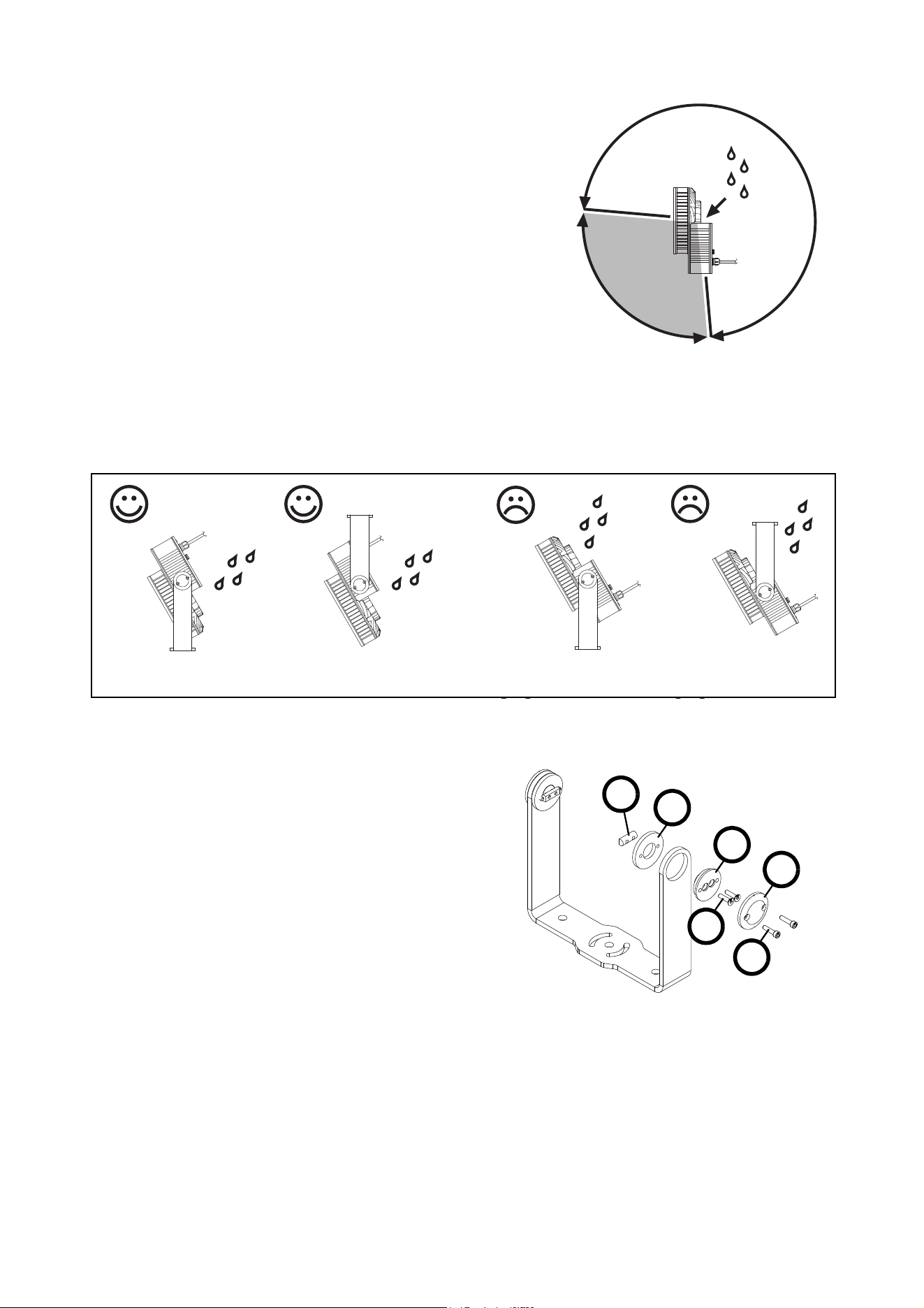
Avoiding water pooling on the power box
See Figure 2. If you install a fixture in the Exterior 400 range
with its power box under the main fixture housing, and if you
aim the light beam downwards from approx. +5° to -95°,
rainwater can form a pool on top of the power box (see
arrow). This can immerse silicone seals in hot and cold water,
possibly mixed with leaves, dirt and/or pollutants, for long
periods.
Provided that the product is installed and serviced as directed
in this manual, it will perform in this orientation without
problem throughout the product warranty period and
afterwards. But to obtain maximum service life from silicone
seals over years of use, we recommend that you follow the
guidelines below.
See Figure 3. If you install the fixture with its light beam
pointing downwards, install it with its power box above the
main housing so that water will drain away from the fixture.
Depending on whether you install the fixture in a standing or hanging position, you may need to invert the
fixture in its mounting yoke so that the power box is above the main fixture housing. See “Inverting a fixture
in its mounting yoke” below.
Inverting a fixture in its mounting yoke
See Figure 4. To invert a fixture in its mounting
yoke:
1. Be ready to support the weight of the fixture
and catch all screws as you remove them.
2. On both sides of the fixture, remove the tilt
lock screws A completely and remove the tilt
adjustment covers B.
3. Supporting the weight of the fixture, remove
the fixture mounting screws C and remove
the mounting discs D and E.
4. Turn the fixture upside down and reinstall the
fasteners in their original positions. Note that
the sliders F let you slide the fixture forward
or backward in the yoke to adjust its position
before you tighten the fixture mounting
screws C through the mounting discs D and
E into the sliders F.
5. Check that all fasteners are secure and that the fixture is secured against falling and causing injury or
damage.
If it is impossible to achieve the desired tilt angle when you have inverted the fixture, the longer yoke
available from Martin™ may provide a solution (see “Extended mounting yoke” on page 8).
Figure 2: Rainwater pooling
+5°
-95°
Rainwater
forms
pool
Rainwater
drains
away
Rainwater
drains
away
Figure 3: Installation examples
Figure 4:Fasteners in yoke
B
D
E
F
A
C
10 Exterior 400 Range user manual
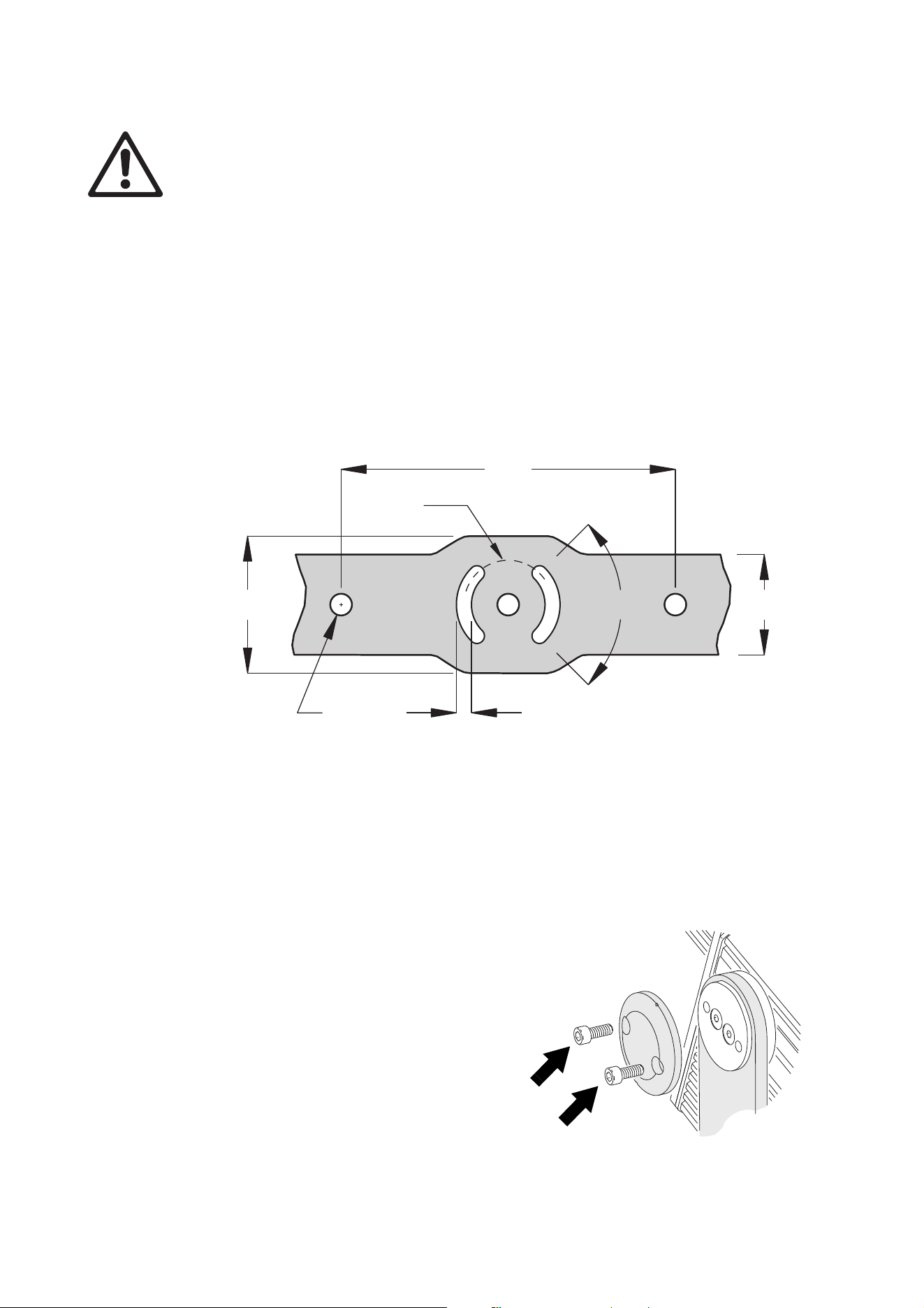
Mounting fasteners
Warning! All fasteners used to mount the Exterior 400 Range must be corrosion-resistant and
strong enough to mount the fixture safely. The washers supplied with the fixture must be installed
directly under the fasteners’ heads when anchoring the yoke base to the installation surface.
The mounting yoke base must be safely anchored to a flat surface. The number and type of fasteners used
will depend on the installation, but use at least three high-strength corrosion-resistant fasteners
(recommended minimum properties: stainless steel A4-70 grade according to ISO 3506 or steel grade 8.8
according to ISO 898-1). All nuts used must be self-locking. Washers must be installed between the head of
each fastener and the yoke base.
The yoke allows the fixture to be manually panned (i.e. rotated horizontally) and tilted for beam aiming
adjustment.
See Figure 5. To mount the fixture, use a 12 mm (1/2 inch) thread diameter bolt in the center hole A. Then
either use two bolts with 12 mm (1/2 inch) shaft diameter passing through holes B or use two bolts with 8
mm (5/16 inch) shaft diameter passing through slots C to anchor the fixture. installing bolts through slots C
will give approximately 90° of pan adjustment.
Install washers under all nuts and bolt heads.
If additional bolts are required to mount the fixture safely, install bolts through holes B and slots C.
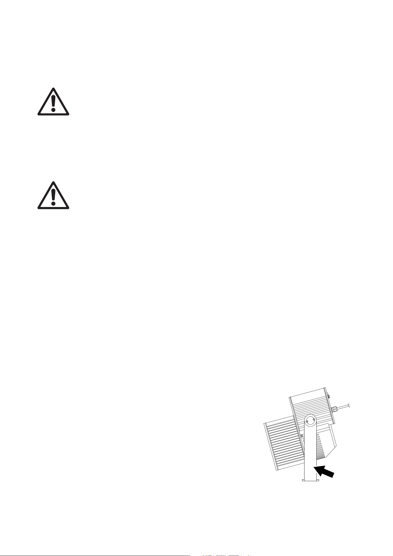
Tilt adjustment
Tilt adjustment can be carried out with the fixture powered on.
To adjust tilt:
1. Put on heat-resistant gloves if the fixture is or has
recently been powered on.
2. See Figure 6. Loosen, but do not remove, the tilt
lock screws (arrowed). Tilt the fixture to the
desired angle and retighten the screws.
If it is impossible to achieve the desired tilt angle, the
longer yoke available from Martin™ may provide a
solution (see “Extended mounting yoke” on page 8).
200
Ø53
82
Ø13
9
60
90°
Figure 5: Mounting yoke attachment points
A
BB
CC
Figure 6: Tilt adjustment
Physical installation 11
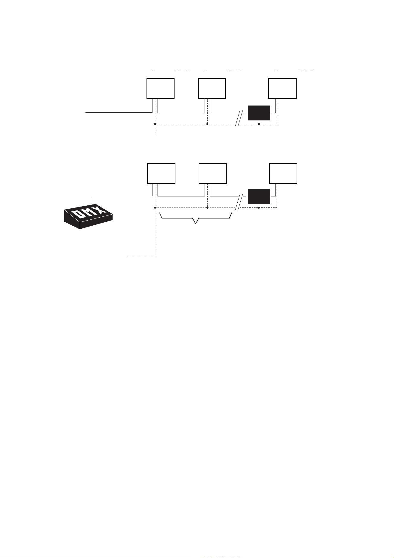
Power and DMX data cable layout
Figure 7 gives an overview of a suitable cable layout. The dotted lines represent AC power
circuits. The solid lines represent the data link.
Cables and cable glands
The power cable supplied with the product is 9.5 mm (0.37 in.) external diameter. The data cable is 6.5 mm
(0.25 in.) external diameter. If you install these cables in cable glands in the installation (when connecting
cables in external junction boxes, for example), make sure that the cable glands are designed to accept
these cable diameters.
The IPON
®
IP68-rated cable glands used for power and data cable entry into the fixture accept cable with 5
- 10 mm (0.2 - 0.4 inch) external diameter. If you replace a cable, install a new rubber seal or a complete
cable gland if the seal is not in perfect condition. If you use a cable with an external diameter that is not
within the range accepted, replace the cable gland with a suitably dimensioned item. Cable glands must be
rated IP68 and suitable for the cable diameter and application. New cable glands can be obtained from
Martin™ (P/N 13102000) or from electrical suppliers.
To replace an IPON cable gland:
1. Lock out power to the installation and allow it to cool for 20 minutes.
2. Loosen the dome nut in the existing gland to release the cable, then unscrew the gland from the rear
cover.
3. Remove the rear cover from the fixture, note connections and disconnect the cable from its terminals.
4. Slide the old gland off the cable.
5. Screw the new gland into the rear cover until it is tight enough to make a seal. Do not overtighten.
6. Pass the cable through the new gland and rear cover, then connect it to its terminals (with reference to
“Replacing the power cable” on page 13 or “Connection pinouts” on page 15 if necessary).
7. Reinstall the rear cover as follows:
a. Read“Managing humidity” on page 7.
b. Check that the seal is in perfect condition.
c. Place the seal and cover in position and drive the cover screws until they are finger-tight only.
d. Cross-tighten the screws evenly in a diagonal pattern, increasing torque gradually in stages to a
maximum torque of 8 Nm (5.9 ft.-lbs.).
8. Tighten the dome nut on the cable gland to seal the cable before applying power.
OPTO-
SPLITTER
Power
230V AC
50 Hz50
Hz
Power
230V AC
50 Hz
Max. 32 luminaires
or 500m. before
opto-splitter
is required.
Max.
32 luminaires
or
500m. before
opto-splitter
is
required.
OPTO-
SPLITTER
DMX
Universe #1Universe #1
DMX
Universe #2
AC power
Fixture Fixture Fixture
OPTO-
SPLITTER
Power
230V AC
50 Hz
Power
230V AC
50 Hz
Max. 32 luminaires
or 500m. before
opto-splitter
is required.
OPTO-
SPLITTER
DMX
Universe #1
DMX
Universe #2Universe
#2
AC power
Fixture Fixture Fixture
OPTO-
SPLITTER
Power
230V AC
50 Hz50
Hz
Power
230V AC
50 Hz
Max. 32 luminaires
or 500m. before
opto-splitter
is required.
Max.
32 luminaires
or
500m. before
opto-splitter
is
required.
OPTO-
SPLITTER
DMX
Universe #1Universe #1
DMX
Universe #2
AC power
Fixture Fixture Fixture
Figure 7: Schematic cable layout diagram
12 Exterior 400 Range user manual
AC power
DANGER! Read “Safety Information” on page 3 before attempting to install an Exterior 400 Range
fixture. Lock out power to the entire installation before working on cables and connections or
removing any cover.
Electrical installation must be carried out by qualified professionals only.
For protection from dangerous electric shock, the fixture must be grounded (earthed). The AC power
distribution system must be fitted with current overload and ground-fault (earth-fault) circuit
breakers as well as a means to isolate fixtures from power and lock out power during service.
Important! Do not connect an Exterior 400 Range fixture to an electrical dimmer system. Doing so
can damage the electronics.
See Figure 7 on page 11 for a schematic diagram of cable layout. If you require help in planning or
dimensioning the power distribution system, please contact your Martin Architectural supplier for
assistance.
If there is a break or cut at any point in a cable (for example at a connection point), and if this is exposed to
water, moisture can be drawn up the inside of the cable due to the vacuum effect of temperature fluctuations
during operation. Ensure that the fixture is protected from the entry of water via the power cable by using
IP65-rated connectors or junction boxes, or by protecting connectors with weatherproof housings.
The Exterior 400 Range is supplied in EU and US models. Both models accept AC power at 100 - 240 V
nominal, 50 or 60 Hz. Do not connect to power at any other voltage or frequency.
The Exterior 400 Range is protected by a 2.5 amp slow-blow primary fuse located on the power PCB inside
the rear cover. See “Fuse replacement” on page 28 for details of changing fuses.
There is no power on/off switch. Power is applied to an Exterior 400 Range fixture as soon as it is connected
to power. Provide a means to disconnect from power or shut down power to fixtures that is easily accessible
and is located close to the fixtures.
Connecting to power
The fixture is supplied with a power cable installed ready for connection to a single-phase 3-wire (live,
neutral, ground/earth) power distribution system at 100 - 240 V nominal, 50/60 Hz.
Important! If you have any other type of distribution system than the one listed above, you must replace the
power cable and connect the fixture to power as described under “Replacing the power cable” on
page 13.
To connect to a single-phase 3-wire (live, neutral, ground/earth) power system:
1. Lock out power to the installation.
2. The power cable color coding for US and EU models is given in Table 1. Connect the conductors in the
power cable to the distribution circuit as follows:
- Connect the green wire (US models) or yellow/green wire (EU models) to ground (earth)
- Connect the white wire (US models) or blue wire (EU models) to neutral
- Connect the black wire (US models) or brown wire (EU models) to live.
Wire color
(US models)
Wire color
(EU models) Conductor Symbol Screw (US)
black brown live L yellow or brass
white blue neutral N silver
green yellow/green ground (earth) or green
Table 1: Conductor identification
AC power 13
3. Check that all installation work is completed and carry out appropriate tests and safety checks before
applying power.
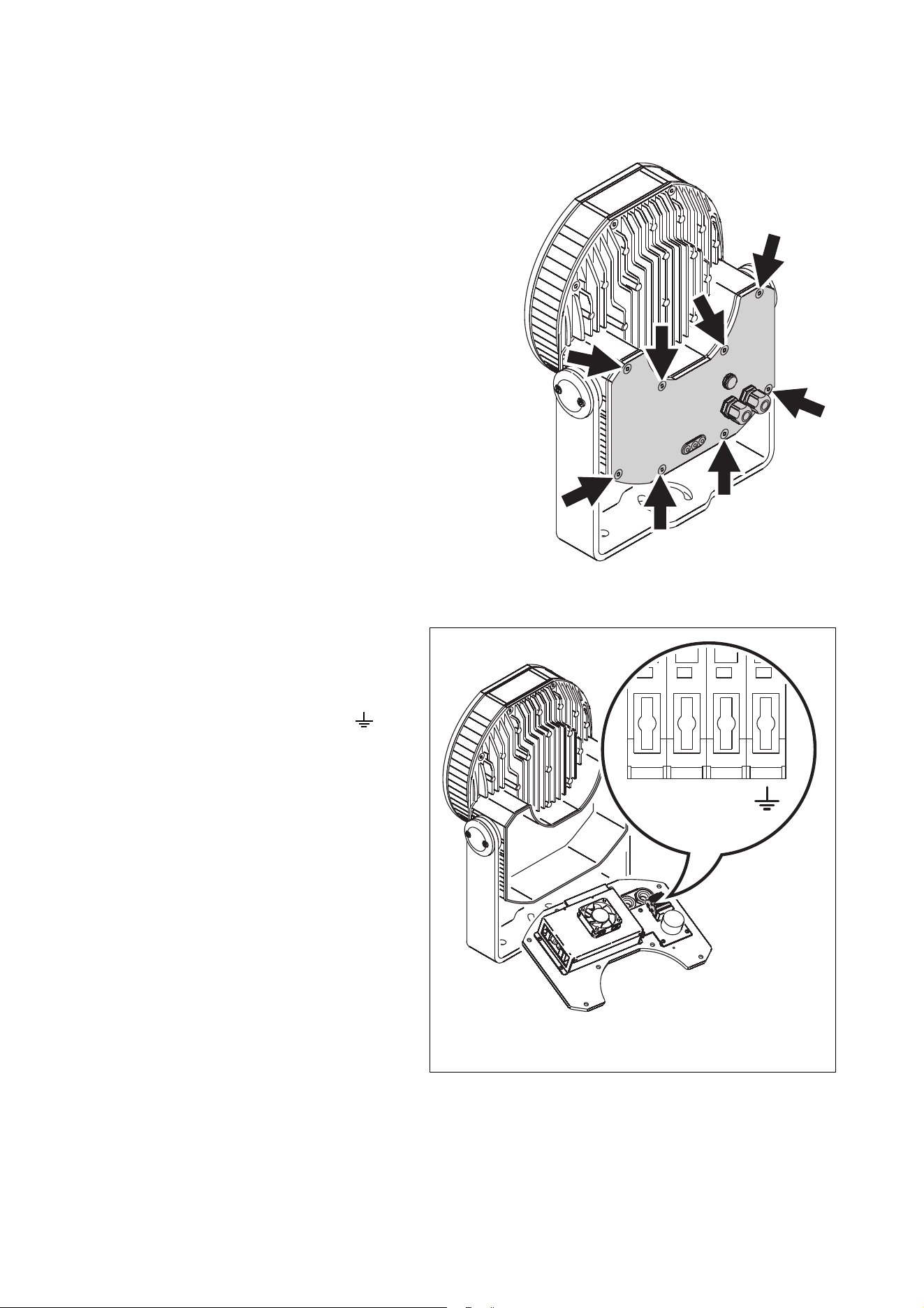
Replacing the power cable
If you replace the supplied power cable, the new
cable must be listed, adequately dimensioned for the
current requirements and suitable for the installation
environment, particularly with regard to water,
pollution, thermal and UV resistance. Use Hypalon
or neoprene rubber-jacket cable rated to 90° C (194°
F) minimum. The conductor size must be 1.5 mm
2
or
16 AWG minimum.
To install a new power cable:
1. Lock out power to the installation and allow the
fixture to cool for at least 20 minutes.
2. Loosen the dome nut in the power cable gland
and then unscrew the gland from the rear cover.
3. See Figure 8. Remove the rear cover retaining
screws (arrowed) and remove the rear cover.
4. Disconnect the existing cable from the power
terminals, then remove it together with the old
cable gland.
5. Pass the new cable through a new cable gland
and through the rear cover.
6. See Figure 9. Connect the
conductors in the new cable to the
spring-loaded power terminals in
the rear cover as follows:
- Connect the ground (earth) wire
to the terminal marked
- If using a single-phase system,
connect the power cable’s neutral
wire to terminal N and connect
the power cable’s live wire to
terminal L. Important! Do not
connect the live wire to
terminal L2 as there is
electrical continuity between
this terminal and terminal N
(see Figure 10).
Figure 8: Rear cover retaining screws
LL N L2L2
Figure 9: Power terminals
14 Exterior 400 Range user manual
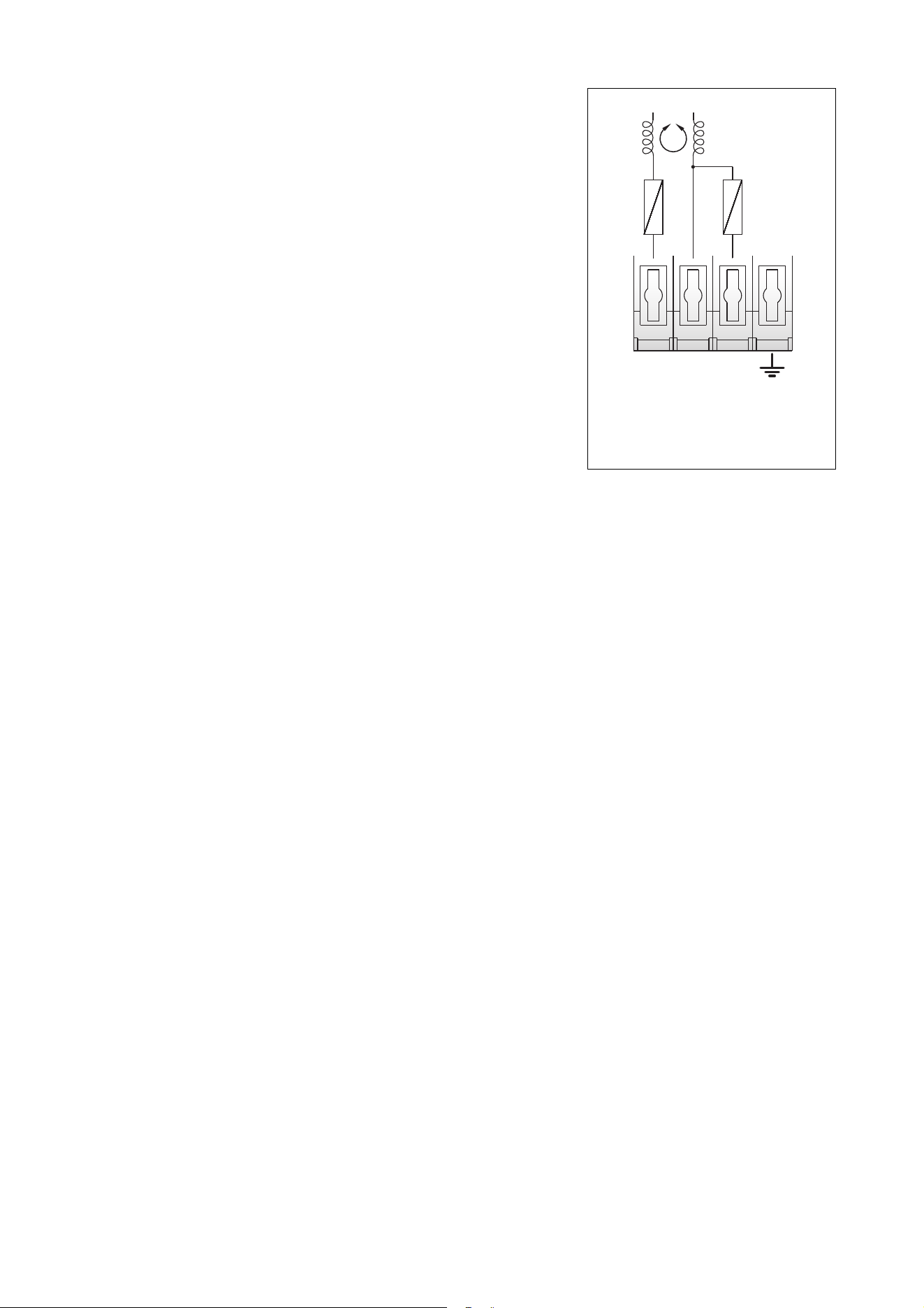
- If using two phases of a three-phase system to obtain
200 - 240 V between two phases, connect one phase to
terminal L and the other phase to terminal L2. Do not
connect anything to terminal N.
- If using a single-phase three-wire earthed mid-point
system (used in certain regions of the USA) to obtain 200 -
240 V between two live conductors, connect one live wire
to terminal L and the other live wire to terminal L2. Do not
connect anything to terminal N.
7. Reinstall the rear cover as follows:
a. Read“Managing humidity” on page 7.
b. Check that the seal is in perfect condition.
c. Place the seal and cover in position and drive the cover
screws until they are finger-tight only.
d. Cross-tighten the screws evenly in a diagonal pattern,
increasing torque gradually in stages to a maximum torque
of 8 Nm (5.9 ft.-lbs.).
8. Screw the new gland into the rear cover until it is tight enough
to make a seal. Do not overtighten.
9. Tighten the dome nut on the cable gland to grip the cable and
make a seal before applying power.
Power plug
You may need to fit the supplied power cable with a plug that is suitable for your AC power outlets. If so,
install a grounding-type (earthed) plug with integral cable grip that is rated 5 A minimum, following the plug
manufacturer’s instructions. Table 1 on page 12 shows some possible pin identification schemes; if pins are
not clearly identified, or if you have any doubts about proper installation, consult a qualified electrician.
Ensure that all connections are sufficiently protected from water.
L2L2NLL
Figure 10: There is continuity
between terminals N and L2
Control data link 15
Control data link
E
xterior 400 Range fixtures must be connected via a control data link for DMX controller or synchronized
(master/client) operation.The following considerations must be taken into account when planning the
data link:
• RS-485 data cable designed for exterior use is required for outdoor installations. RS-485 cable has low
capacitance and a characteristic impedance of 85 to 150 Ohms. It is electrically shielded and has at least
1 twisted pair of conductors. The minimum recommended wire size is 0.25 mm
2
(24 AWG) for runs up to
300 meters (1000 ft.) and 0.32 mm
2
(22 AWG) for runs up 500 meters (1640 ft). CAT 5 network cable
designed for direct burial can be used in outdoor installations, but you are recommended to run it inside
conduit.
• The maximum permitted control data cable length before a control signal amplifier is required is 500
meters (1640 ft.).
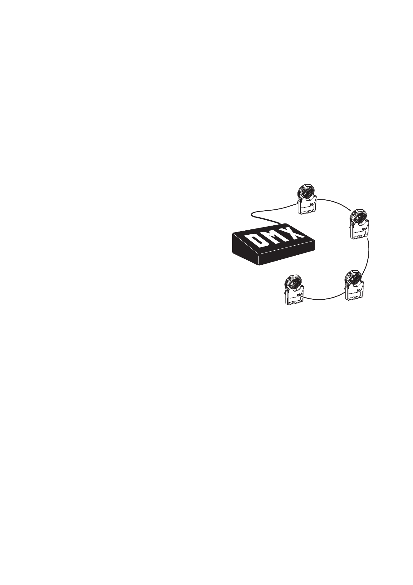
• Fixtures must be ‘daisy-chained’, i.e. the data
cable must be connected in one single chain of
fixtures as shown in Figure 11.
• Each chain may connect a maximum of 32
fixtures.
• An optically isolated amplifier-splitter such as the
Martin RS-485 Opto-Splitter (P/N 90758060)
must be used to:
- extend a link beyond 500 meters (1640 ft.)
- extend the link to include a further maximum
32 fixtures, or
- branch the link into further single chains, each
containing 32 fixtures. The Martin
Opto-Splitter allows a link to be branched into
four new chains.
• Each chain on the link must be terminated by
placing a 120 ohm resistor (available from Martin,
P/N 04150308) across the data hot (+) and cold
(-) conductors of the last fixture on the chain.
• Long parallel runs of AC power and control data cables may cause interference on the data link and must
be avoided. Even if not required by law, use separate conduits for power and data cables.
• One DMX universe has 512 DMX control channels available. If individual control of the fixtures in an
installation is required, each fixture must be given its own channels until the limit of 512 is reached. At this
point, a new DMX universe must be created before more fixtures can be added.
• The number of fixtures that can be individually controlled in one DMX universe depends on the number of
DMX channels they use. if an Exterior 400 fixture is set to HSI mode, for example, that fixture will require
3 DMX channels (one channel for hue, one for saturation and one for intensity). The total number of
Exterior 400 Range fixtures set to HSI mode that can be linked in one DMX universe will therefore be
512/3 = 170 (note that an amplifier-splitter must be used each time the limit of 32 devices on one branch
is reached).
Connection pinouts
XLR connection
XLR connectors are suitable if DMX cable is used for the data link. XLR pin numbers are normally marked
on connectors. Connectors must be wired using the standard XLR DMX pin-out:
• Pin 1: Cable shield
• Pin 2: DMX Data 1 - (cold)
• Pin 3: DMX Data 1 + (hot)
Pins 4 and 5 on 5-pin XLR connectors are available for Data 2 connections in DMX 512-A or similar
systems. They must be wired as follows:
• Pin 4: DMX Data 2 - (cold)
• Pin 5: DMX Data 2 + (hot)
Figure 11: DMX link
16 Exterior 400 Range user manual
To avoid ground/earth loop interference, ensure that the DMX cable shield does not come into contact with
the shell or body of XLR connectors.
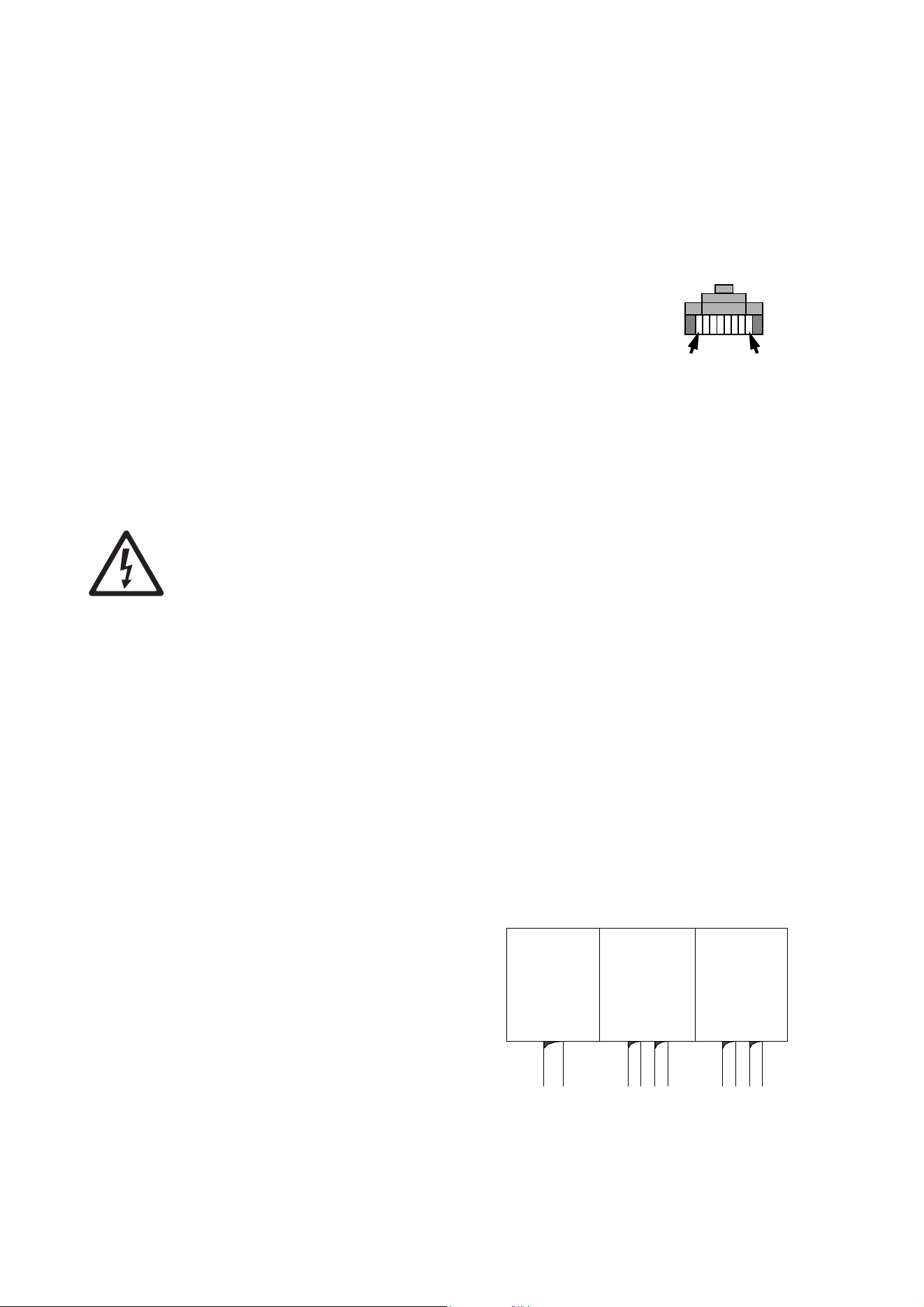
RJ-45 connection
RJ-45 connectors are suitable if CAT 5 cable is used for the data link. RJ-45 cable connector pins are
numbered from the left looking at the face of the connector with the locking clip on top (see Figure 12).
Connectors must be wired according to the 568-B system using the standard RJ-45 pin-out for DMX
applications:
• Pin 1 (White/orange): DMX data hot (+)
• Pin 2 (Orange): DMX data cold (-)
• Pins 7 (White/brown) and 8 (Brown): Common
Pins 3 and 6 are available for Data 2 connections in DMX 512-A or
similar systems. They must be wired as follows:
• Pin 3 (White/green): Available for Data 2 hot (+)
• Pin 6 (Green): Available for Data 2 cold (-)
Pins 4 and 5 are not used in currently available lighting control
systems but can be wired as follows:
• Pin 4 (Blue)
• Pin 5 (White/blue)
Connecting the data link
DANGER! Lock out power to the entire installation before working on cables and connections or
removing any cover.
Warning!Make sure that data connections are totally protected from water, or moisture may be
drawn up the inside of the cable due to the vacuum effect from the heat generated during operation.
The fixture is supplied with a 1.8 meter (5.9 ft.) data cable tail for data connection. The cable contains both
input and output conductors that are identified as follows:
• 1 x shield = data input and output common
• 2 x white wires = data input and output hot (+)
• 1 x green wire = data input cold (-)
• 1 x brown wire = data output cold (-)
To connect a fixture to the data link:
1. Connect the conductors in the fixture’s cable tail to the data cable respecting the above color code. If
required, install input and output connectors on the data cable respecting the pinouts described in
“Connection pinouts” on page 15. Standard procedure is to use a male connector on a fixture or its cable
tail for data input and a female connector for data output. Do not connect the shield conductor to ground
(earth) or allow it to come into contact with a connector shell, as this may cause interference.
2. Protect connectors in a weatherproof housing if they are not totally weatherproof.
Replacing the data cable
If you replace the supplied DMX data cable
tail, connect the new cable’s conductors to the
data terminals as shown in Figure 13 and
follow the instructions under “Control data
link” on page 15 to ensure correct
weatherproofing.
If the new cable is not the same diameter as
the supplied cable, or if the cable gland seal is
not in perfect condition, install a new rubber
seal or complete cable gland.
Pin 1 Pin 8
Figure 12: RJ-45 cable
connector pins
Figure 13: Data terminals
Data input
and output
hot (+)
both white
wires
Data input
and output
cold (-)
green and
brown wires
Shield
braided
Fixture setup 17
Fixture setup
The Martin MUM (Multi-Utility Manager) application allows you to program and configure Martin Exterior
400 Range fixtures from a laptop PC and features an intuitive GUI (graphic user interface).
Using MUM, you can connect to and set up one fixture at a time. Refer to the MUM user manual for
instructions on installing and starting the MUM application.
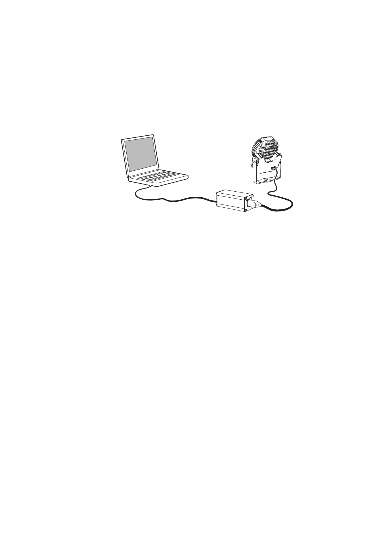
Connecting a PC with MUM
To connect a PC with MUM to an Exterior 400 Range fixture:
1. Obtain the MUM application, a Martin DABS1 adaptor and interface cables. These are available as a set,
P/N 90758090, from Martin.
2. Connect the DABS1 adaptor to your PC using the USB cable.
3. Connect the DABS1 adaptor to the fixture using an XLR connector connected to the data link. Note that
you may only connect to one fixture at a time.
4. Apply power to the fixture and start the MUM application. The application will automatically detect the
fixture if it is powered on and correctly connected. It will also retrieve and display information and current
settings from the fixture.
Figure 14: Connecting to a PC with MUM
18 Exterior 400 Range user manual
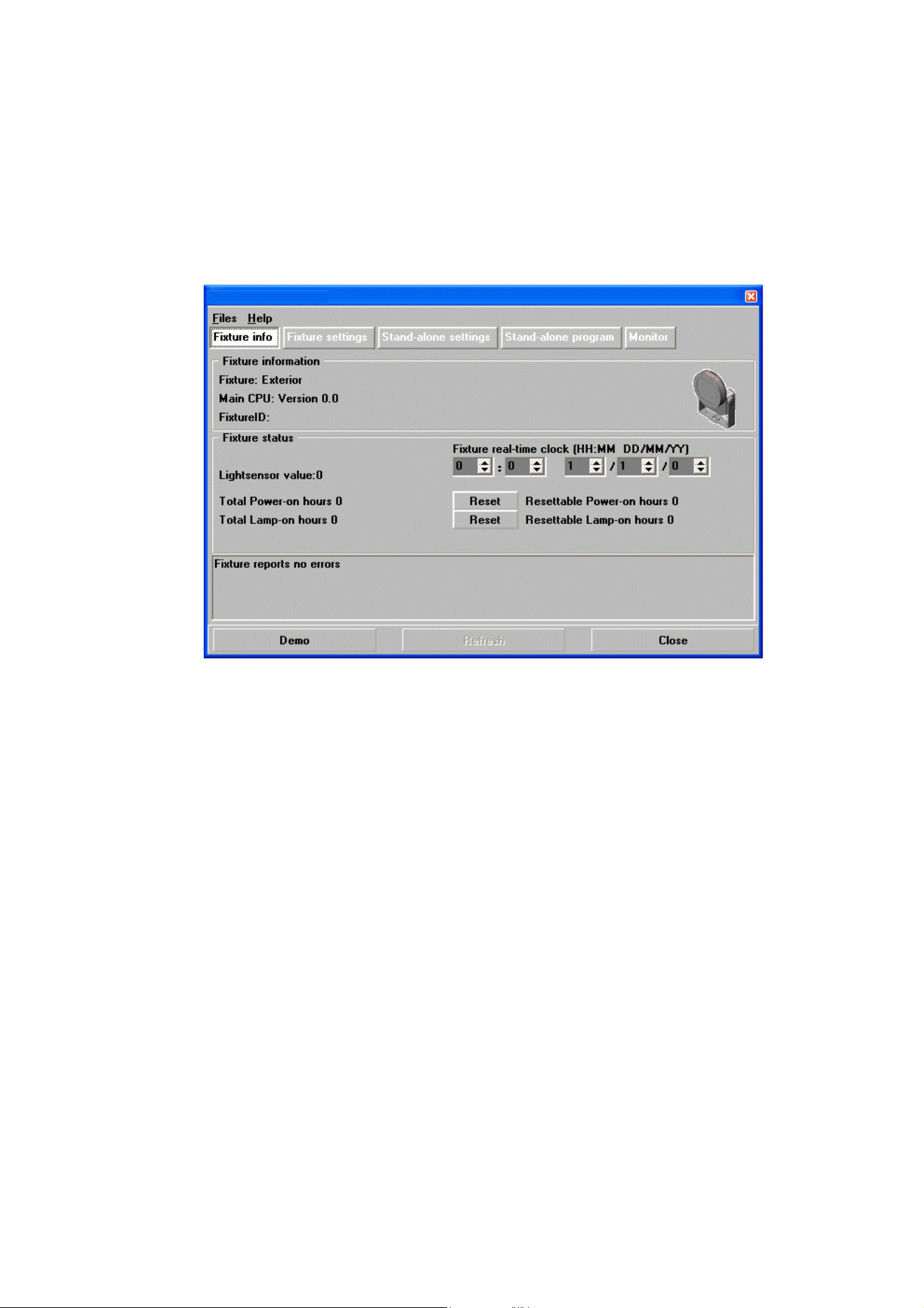
Configuring a fixture with MUM
Setting the clock
Exterior 400 Range fixtures have a battery-operated 24-hour clock that is used to start and stop stand-alone
operation.
To set the clock:
1. Click on the Fixture Info button in MUM:
2. Using the Fixture real-time clock spin buttons, set the fixture to the current time (expressed in the
24-hour clock in hours and minutes) and date. The time will be updated in the fixture in real time.
Setting DMX address and DMX control mode
If individual control of each Exterior 400 Range fixtures is required, each fixture must be set up to receive
instructions from the DMX controller on a group of DMX channels that are not used by any other device in
its DMX universe. The DMX address, also known as the control address or start channel, is the first of these
channels. Each fixture uses this channel and the channels immediately above it to receive instructions.
Exterior 400 Range fixtures use 1, 2, 3, or 4 DMX channels, depending on model and DMX color control
mode. For example, if a fixture’s DMX address is set to 1 and the fixture is in RGB DMX mode, it will use
channels 1 - 3. Channel 4 will be available as the DMX address for the next fixture.
If two or more identical fixtures are set up with the same DMX address and in the same DMX mode, they will
receive the same instructions and behave identically. Setting up identical fixtures with the same address is
a good tool for troubleshooting unexpected behavior and an easy way to achieve synchronized action.
Figure 15: Fixture info window
Fixture setup 19
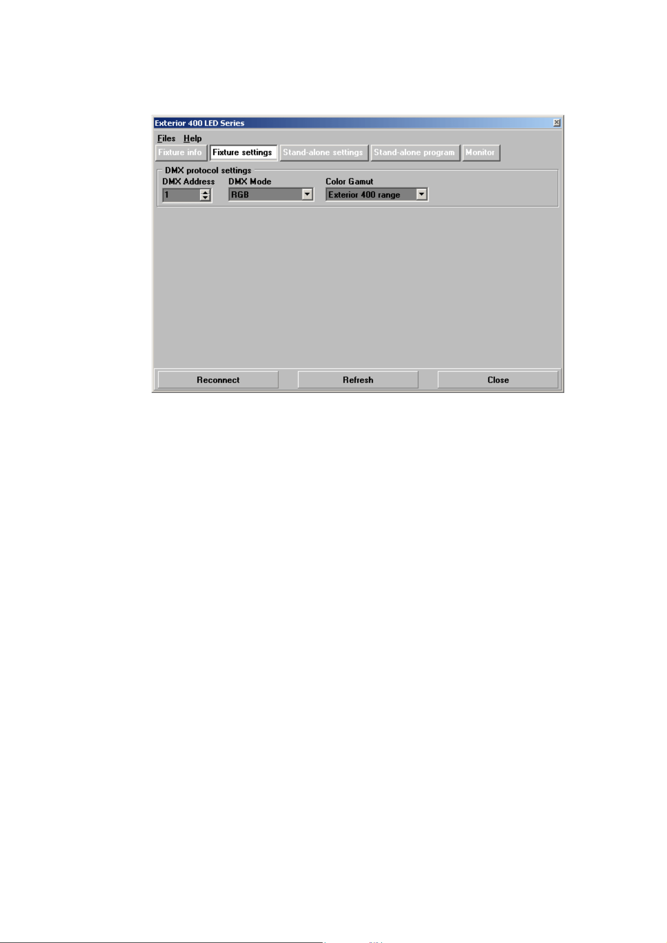
DMX Address
To set the DMX address using MUM, click on the Fixture settings button and use the DMX Address spin
buttons to set the fixture’s DMX address. The DMX address will be updated in the fixture in real time.
DMX Mode
The DMX Mode setting allows you to set the fixture to respond in various control modes.
To set the DMX mode using MUM, click on the Fixture settings button and use the DMX Mode drop-down
dialog box to select the desired mode. The DMX mode will be updated in the fixture in real time.
Bear in mind that changing the DMX mode may affect the number of DMX channels the fixture uses.
The following modes are available:
Exterior 400, Exterior 410
• RAW (Individual control of red, green, blue and white LED groups - uncalibrated)
• RGB (red, green, blue - calibrated, all LEDs including white can be activated to optimize color and
intensity)
• HSI (hue, saturation, intensity - calibrated)
• HSIC (hue, saturation, intensity, color temperature - calibrated)
Exterior 420
• RAW (Individual control of warm white and cold white LED groups - uncalibrated)
• CT (intensity, color temperature - calibrated)
Exterior 430
In Exterior 430 red, green and blue single-color fixtures, RGB & HSI modes let you fine-tune the fixture’s
main color by adding a little of the other two primary colors.
• RGB (red, green, blue - calibrated if Color Gamut set to Exterior 400 Range, uncalibrated if Color
Gamut set to Fixture)
• HSI (hue, saturation, intensity - calibrated if Color Gamut set to Exterior 400 Range, uncalibrated if
Color Gamut set to Fixture)
• I (intensity - calibrated)
Figure 16: Fixture settings window

20 Exterior 400 Range user manual
Options for managing color in different fixtures
The different fixture types in the Exterior 400 Range use different LEDs, and it is normal that
these have different color gamuts. The Color Gamut setting lets you take this into account and set the
fixture to either Exterior 400 Range or Fixture:
• The Exterior 400 Range setting sets all Exterior 400 Range fixture types to display colors within the
same color gamut (i.e. within the same color saturation limits). The Exterior 400 Range setting ensures
that the same colors can be obtained from different fixture types, but it limits color saturation if necessary.
• The Fixture setting optimizes color saturation for one specific fixture type. Color is identical with other
fixtures of the same type, but there may be slight color differences when you try to display the same color
close to or at its maximum saturation on different fixture types.
The only exception to this is the Exterior 430, in which the Fixture setting is uncalibrated and there may
be very slight differences in color with other Exterior 430 fixtures of the same type: For example, two
Exterior 430 red fixtures set to Fixture may not display exactly the same red. To obtain an identical red,
set both fixtures to Exterior 400 Range.
Note that the Color Gamut setting only affects fixtures when they are set to a DMX mode that is calibrated
(see "DMX Mode" on page 19) and has no effect on fixtures that are set to RAW DMX modes.
A simple formula to obtain the best results:
•Use the Exterior 400 Range setting where color evenness across different fixture types (or, in the
case of the Exterior 430, across different fixtures) is more important than obtaining maximum
color saturation.
•Use the Fixture setting where the installation only consists of one fixture type or where obtaining
maximum color saturation is more important than color evenness across different fixture types.
Operation 21
Operation
Exterior 400 Range fixtures can be operated using a DMX controller or programmed to run a stand-alone
light show without DMX control.
Ambient temperatures
The Exterior 400 Range can be operated at ambient temperatures from -30° C (-22° F) to 45° C (113° F).
At temperatures below 0° C (32° F), leave the fixture permanently powered on, even if LEDs are dimmed to
zero because light output is not required. The standby power will provide a little heat and help protect
circuits and components from the effects of low temperature.
DMX control
In DMX-controlled operation, the options available to a DMX controller depend on which DMX mode the
fixture is set to (see “DMX Mode” on page 19).
The section “DMX protocols” on page 31 gives details of all the modes available in all the fixtures in the
Exterior 400 Range and which DMX channels are used to control color, color temperature and intensity in
the different modes.
Stand-alone operation
In stand-alone operation, the fixture executes color changes at set intervals and speeds, at pre-defined
periods during the day, and/or when the light level falls below a defined level. The term stand-alone means
that the Exterior 400 Range is not connected to a control device, but is pre-programmed with a sequence of
up to 20 scenes that play continuously in a loop.
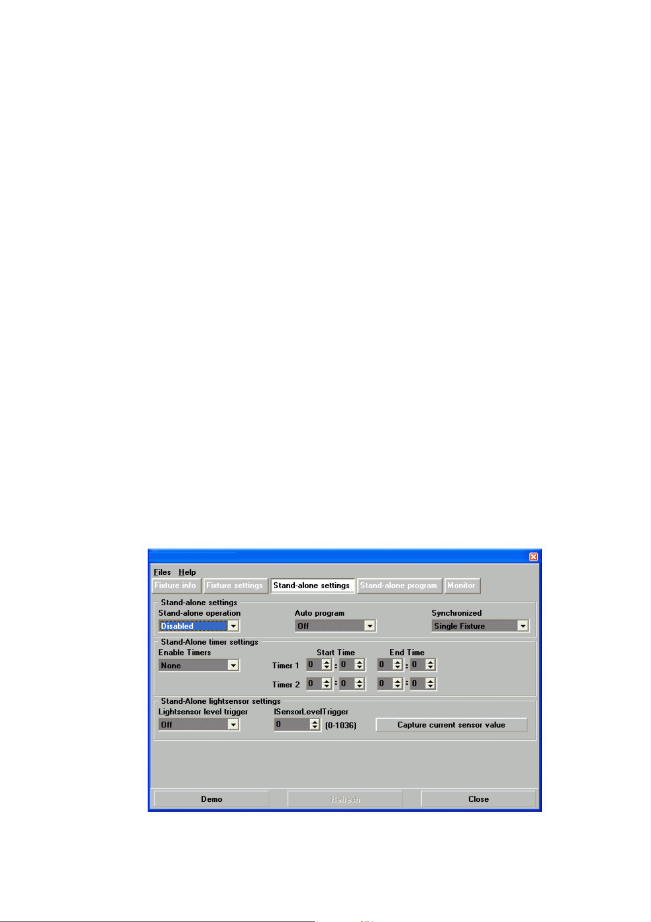
Configuring stand-alone settings
First, the fixture needs to be configured to know if and when to activate a stand-alone program. Connect a
PC running the MUM application as described in "Connecting a PC with MUM" on page 17, and click on the
Stand-alone settings button (see Figure 17).
Figure 17: Stand-alone settings window
22 Exterior 400 Range user manual
Stand-alone operation can be set to:
• start automatically as soon as power is applied
• respond to a timer trigger that activates operation for one or two periods in a 24 hour period, or
• respond to a light-level trigger that uses a light sensor to activate operation when ambient light is below a
certain level.
If both the timer and the light-level trigger are used, operation starts whenever it is darker than the light-level
setting, and within the times set.
Enabling stand-alone operation
To enable stand-alone operation, set Stand-alone operation to Enabled.
Starting automatically
To set stand-alone operation to start automatically, set Auto program to On. The fixture will now start
stand-alone operation automatically as soon as power is applied and no DMX signal is being received.
Setting a timer trigger
To set a timer trigger:
1. Make sure that the correct time has been set on the fixture’s built-in clock (see "Setting the clock" on
page 18).
2. Select None, Timer 1, Timer 2 or Both Timers in the Enable Timers box.
3. Use the Start Time and End Time spin buttons to set a period of stand-alone operation on the selected
timer(s).
Setting a light-level trigger
To set a light-level trigger:
1. Set Light level sensor trigger to On.
2. Set the light level that triggers stand-alone operation using the Trigger level spin button, or press
Capture current sensor value to set the current ambient light level to trigger stand-alone operation.
To avoid false triggering by sudden light changes (caused by vehicle headlights or clouds, for example), the
light level must remain above or below the trigger threshold for 5 minutes to activate the trigger.
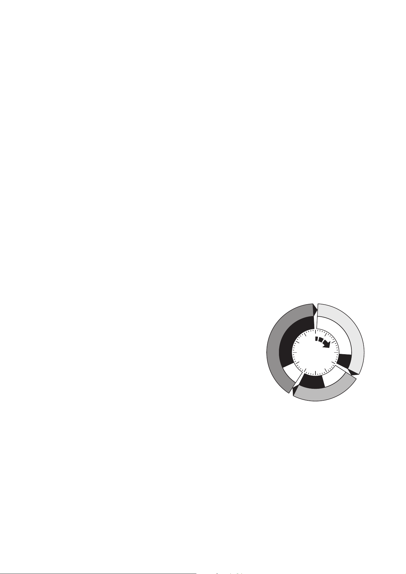
Programming stand-alone operation
About scenes
A stand-alone light show consists of scenes. Each scene is a
particular lighting effect with predetermined color, intensity and
duration. Up to 20 scenes can be programmed into the Exterior
400 Range’s program memory.
Each scene has a dynamic part – the fade – during which effects
move to the scene’s programmed positions, and a static part – the
wait – where effects do not change.
The duration of the fade and wait is programmed individually for
each scene. The fade time may be 0 - 120 seconds; the wait time
may be 1 second to 12 hours. The total time it takes a scene to
execute is the sum of the fade and wait times.
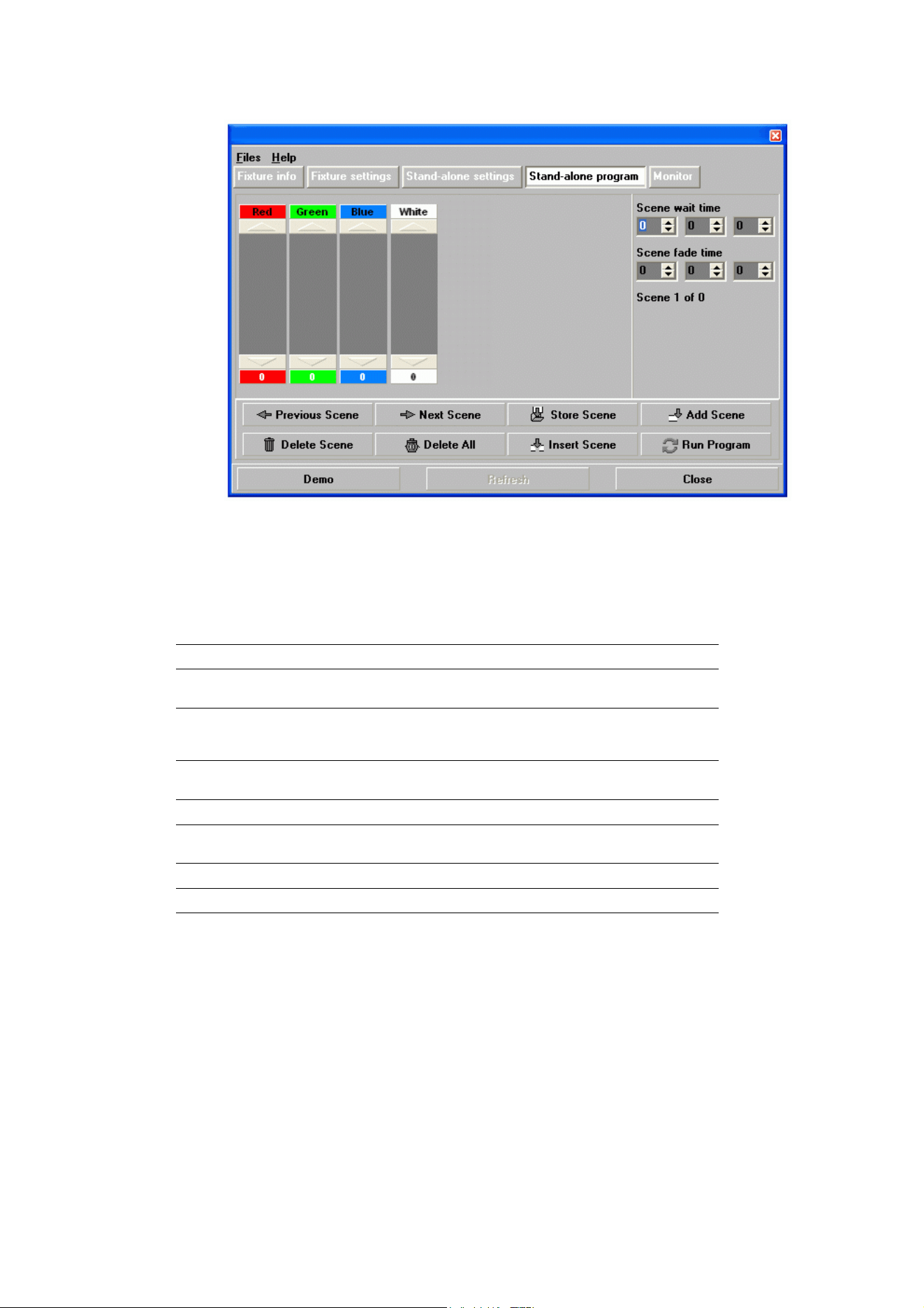
Programming scenes
To program a scene:
1. click on the Stand-alone program button (see Figure 19).
2. Depending on which DMX mode the fixture is set to, the stand-alone programming window will show
columns for RGB, RGBAW, HSI or HSIC. Apply values by setting levels in each column.
Fade
Fade
S
c
e
n
e
1
S
c
e
n
e
1
S
c
e
n
e
3
S
c
e
n
e
3
S
c
e
n
e
2
S
c
e
n
e
2
Wait
Wait
Wait
Fade
Figure 18: Scene timing
Operation 23
3. Select a fade time and a wait time for the scene.
Scene management
Once you have specified values for the effects and fade and wait times for the scene, you can store and
manage scenes using the commands available at the bottom of the Stand-alone program window:
When the program is run by applyi
ng the Run program command, scenes execute in a continuous,
ascending loop.
Synchronizing stand-alone operation
If you are running multiple fixtures on a data link, you can synchronize action so that all fixtures start their
programmed shows and start fading to the next scene at the same time.
Setting master and client fixtures
In synchronized operation, one fixture is set as the master and the others are set as clients. Each fixture
must be programmed with its own show. When the master fades to the next scene or starts its show from
the beginning again, it tells each client fixture to fade to its next scene or start its show again. In other
words, each client fixture will run its show repeatedly in a cycle, changing scene when prompted to by the
master, until the master finishes its own show and signals that all fixtures should start from the first scene
once again.
Store scene Save settings in the current scene.
Add scene Save settings in a new scene at the end of the current sequence of
scenes.
Insert scene Save settings in a new scene before the current scene. Tip: Think of
the Add and Insert commands as Save commands, to be used as the
last step after programming all effects.
Delete scene Remove the current scene from memory. Scenes after the deleted
scene are renumbered.
Next scene Step to the next scene.
Previous
scene
Step to the previous scene.
Delete all Remove all scenes from the fixture’s memory.
Run program Run the scenes in the programmed light show.
Figure 19: Stand-alone programming window
24 Exterior 400 Range user manual
Before running synchronized operation, you must set fixtures to one of the following in the Synchronized
drop-down dialog box (see Figure 17):
• Single Fixture: operates in stand-alone mode independently of other fixtures
• Master: sends trigger signals to other fixtures, or
• Synchronized: client – receives trigger signals from master fixture.
No more than one fixture may be the master. Any fixt
ure on the link, regardless of its position, may be the
master. All other fixtures must be set as clients.
Combining with other fixtures
An Exterior 400 Range running a stand-alone show can perform synchronized scene changes with other
Exterior 400 Range fixtures as well as Martin fixtures of the following types:
Stand-alone programming tips
If you want to keep things as simple as possible when programming synchronized operation, ensure that:
1. Every
fixture has the same number of scenes.
2. Scene times are a few seconds longer on the master fixture than on client fixtures (this will ensure that
client fixtures always have time to finish scenes before the master tells them to start the next scene).
It is important to note that the only commands transmitted by the master are scene change and show start
commands. No data about the appearance of the scene is transmitted between fixtures.
If you are programming a group of fixtures
to
perform the same scenes with
synchronized master/client triggering, we
recommend that you:
1. Us
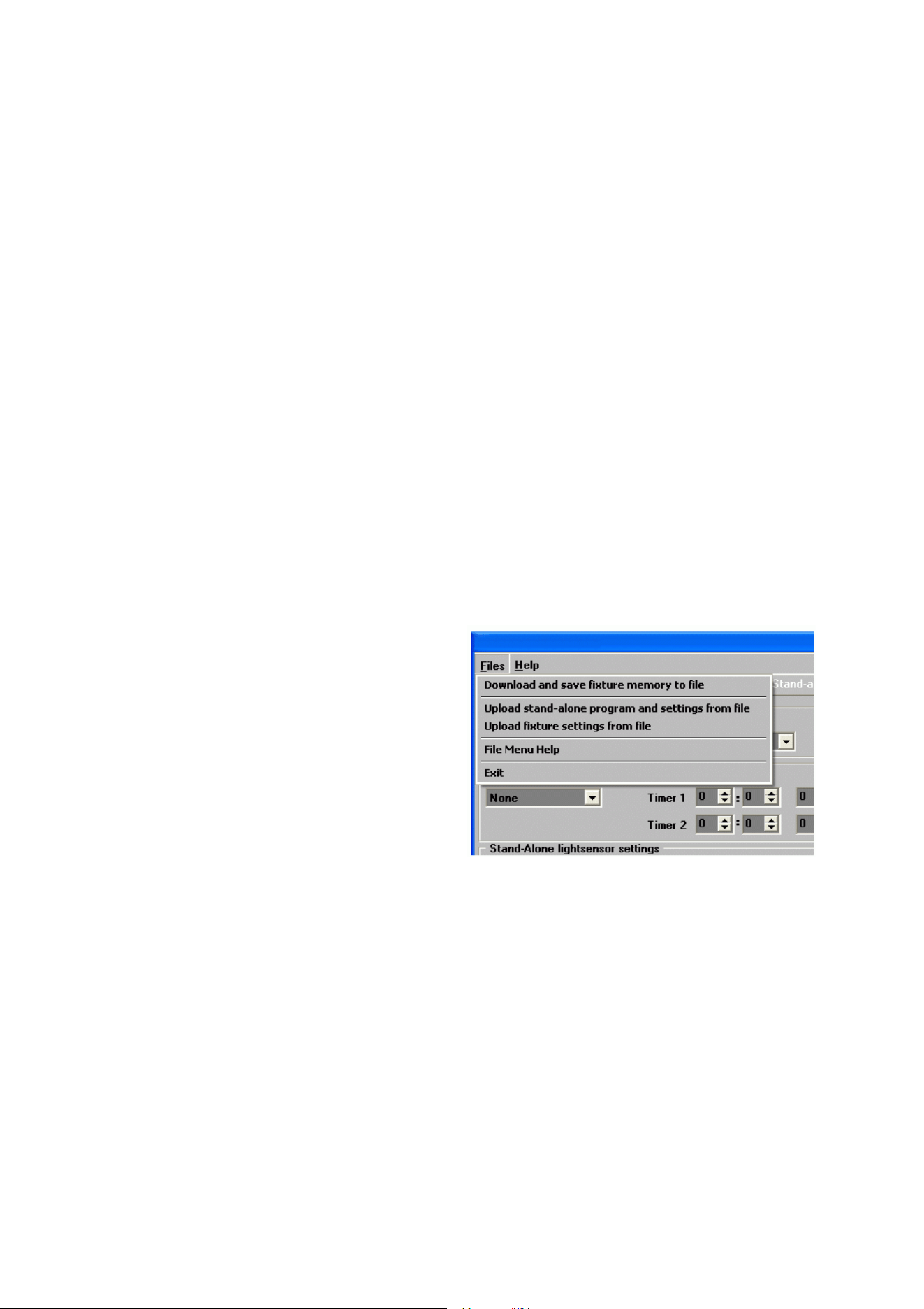
e MUM to program a show on one
client fixture
2. Download and save this fixture’s
memory (program and settings) to
your PC using MUM’s Files menu (see
Figure 20), and then
3. Upload the program and settings to
each subsequent fixture that you
connect to.
For a more detailed explanation of
synchronized operation and how
advanced effects can be created by
programming fixtures with a different
number of scenes, see the next section.
Synchronized stand-alone operation: detailed description
Note: This section gives advanced information about stand-alone synchronized operation. You only need
to read it if you require help with problem diagnosis or if you want to program advanced
synchronized light shows.
The principles in stand-alone synchronized operation are as follows:
1. A scene contains a fade section, followed by a wait section
2. Each fixture can be individual
ly programmed with up to 20 scenes, and each scene can have its own
individual fade and wait times.
3. Scenes are numbered from 0 to 19.
4. In synchronized operation, one master fixture issues commands to the other client fixtures to “go to
scene xx”, where xx is the scene number that the master will execute next.
5. If a client has fewer scenes than the master, it will derive which scene to go to by dividing the number of
the scene it has been commanded to go to (scene 5, for example) by the total number of scenes that the
• Exterior 200 LED
• Exterior 1200 Wash
• Exterior 1200 Image Projector
• Exterior 200
• Exterior 600
• Exterior 600 Compact
• Inground 200 CMY
• Inground 200 6-Color
• FiberSource CMY150
• Imager range
• Alien 02 range
•MiniMAC Maestro
• smartMAC
Figure 20: Managing fixture settings and stand-alone
programs as files
Operation 25
c
lient fixture has (4, for example) in whole numbers (no decimal places). In this example 5 divided by 4
results in 1, with 1 remainder. This remainder will be the number of the scene that the client fixture starts
- scene 1. Generally though, when a Client fixture reaches its own last scene before the Master fixture, a
“go to scene xx” message will result in the first scene being played.
6
. If a client has more scenes than the master calls, the last scenes in the client will never be executed, as
is the case with scene S4 in the following example.
7. In synchronized operation, the wait time is determined by the master. Every client fixture fades and waits
at its own rate and then remains in the “wait” state until it receives a “start scene xx” command from the
master.
8. A client fixture will not listen for the next message from the master fixture before it has finished its current
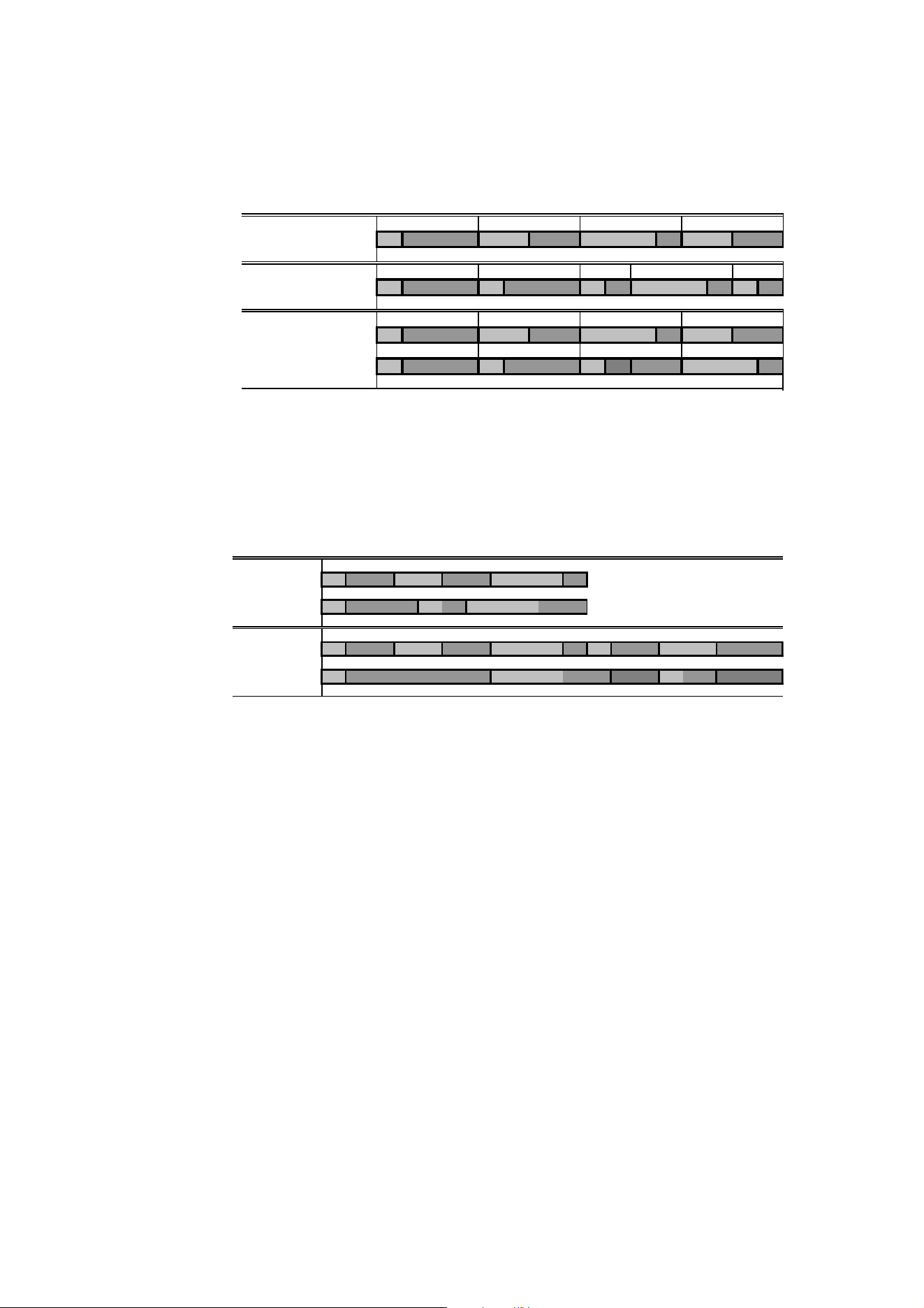
scene. This may result in a client skipping a scene if the client has a longer scene time than the master.
Note that in the following example, the scenes in the client run out of their programmed sequence
because scenes 0 and 2 on the client are longer than the corresponding scenes on the master.
F=fade, W=wait Timeline =>
M0 M1 M2 M3
Programmed in Master F W F W F W F W
S0 S1 S2 S3 S4
Programmed in Client
F W F W F W F W F W
Result M0M1M2M3
FW FWF WFW
S0 S1 S2 S3
FW FW FW ----F W
M=master, S=client
F=fade, W=wait Time >
Programmed M0 M1 M2
Master F W F W F W
S0 S1 S2
Client
F W F W F W
Result M0 M1 M2 M0 M1
Master F W F W F W F W F W
S0 S2 S1
Client
F W F W .. .. FW .. ..
26 Exterior 400 Range user manual
Service and maintenance
DANGER! Read “Safety Information” on page 3 before carrying out service or maintenance work on
the Exterior 400 Range. Lock out power to the entire distribution system before servicing or
opening any cover.
Important! The Exterior 400 Range requires regular service and maintenance to maintain reliable
operation and protect the investment it represents. Excessive dirt and particle buildup degrades
performance, causes overheating and will damage the fixture. Damage caused by inadequate
cleaning or maintenance is not covered by the product warranty.
Important! As with electronic components in general, Exterior 400 Range fixture PCBs are sensitive
to ESD (electrostatic discharge). Take precautions to avoid ESD damage during service.
The service and maintenance procedures described in this section must be carried out by qualified
professionals only. Any service procedures not described in this section must be carried out by the Martin
Service organization or its authorized agents.
It is Martin policy to use the best quality materials available to ensure optimum performance and the longest
possible component lifetimes. However, optical components in all lighting fixtures are subject to wear and
tear over the life of the fixture, resulting in gradual changes in color rendition, for example. The extent of
wear and tear depends heavily on operating conditions, maintenance and environment, so it is impossible to
specify precise lifetimes for optical components. However, you will eventually need to replace LEDs if their
characteristics are affected by wear and tear after an extended period of use and if you require fixtures to
perform within very precise optical and color parameters.
When installing front and rear covers, use a torque driver and cross-tighten screws (tighten screws opposite
each other gradually in steps, working around the cover). Tighten front and rear cover screws to 8 Nm (5.9
ft.-lbs.).
Cleaning
Regular cleaning is essential for fixture life and performance. Buildup of dust and dirt degrades the fixture’s
light output and cooling ability.
Cleaning schedules will vary greatly depending on the operating environment. It is therefore impossible to
specify precise cleaning intervals for the Exterior 400 Range. Inspect fixtures within their first few weeks of
operation to see whether cleaning is necessary. Check again at frequent intervals. This procedure will allow
you to assess cleaning requirements in your particular situation. If in doubt, consult your Martin dealer about
a suitable maintenance schedule.
Do not use products that contain solvents, abrasives or caustic agents for cleaning, as they can cause
surface damage to the fixture.
Warning! Do not use a high-pressure water jet for cleaning. Take care not to damage seals and
wiring during cleaning.
The Exterior 400 Range’s aluminum housing and front glass can be cleaned with mild detergents such as
those for washing cars. To clean the housing and front glass:
1. Isolate the fixture from AC power and allow the fixture to cool for 20 minutes.
2. Visually check that the silicone seals are in good condition. If any seal shows signs of damage or loss of
water resistance, stop cleaning the fixture and contact a Martin authorized service technician for seal
replacement.
3. If seals are in good condition, rinse off loose dirt with a hosepipe or low-pressure water spray. Do not
spray water into the heat exchanger.
4. Wash the aluminum housing and front glass using warm water with a little mild detergent and a soft
brush or sponge. Do not use abrasive cleaners.
5. Rinse with clean water and wipe dry.
Service and maintenance 27
Installing and removing a diffuser filter
Important! Install diffuser filter sheets with the matt, textured surface facing in towards the LEDs and the shiny
surface against the front glass.
Exterior 400 Range fixtures are supplied with no diffuser filter installed and narrow, medium and wide
diffuser filters packed separately with each product. Diffuser filters soften the output from the LEDs and alter
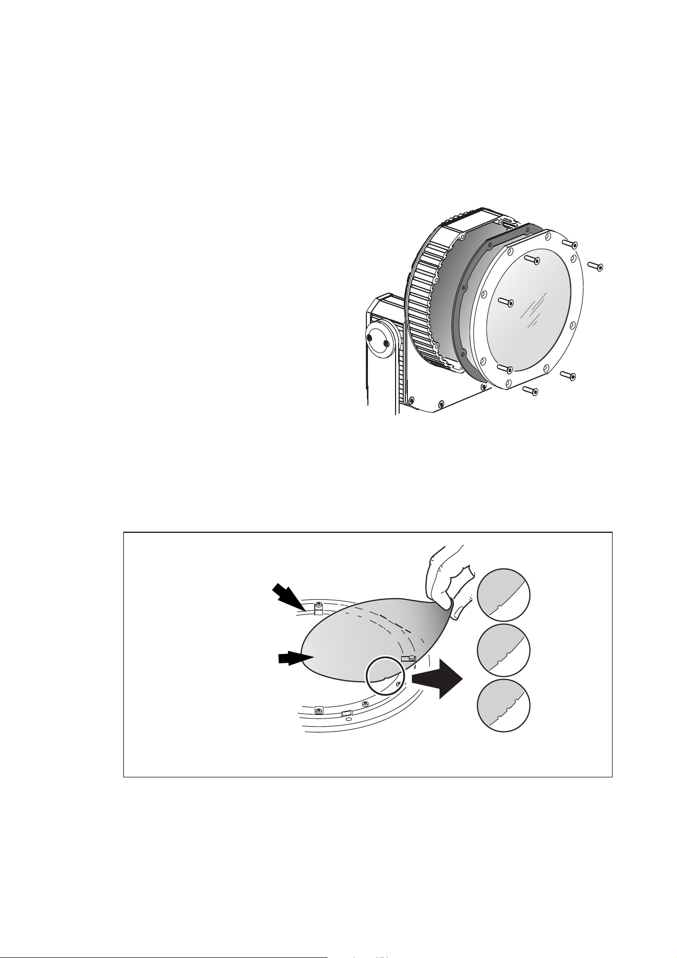
the beam angle. See Figure 22. Diffuser filters are marked with notches to identify them.
To install a diffuser filter:
1. Isolate the fixture from power. If the fixture has been in use, allow it to cool for at least 20 minutes.
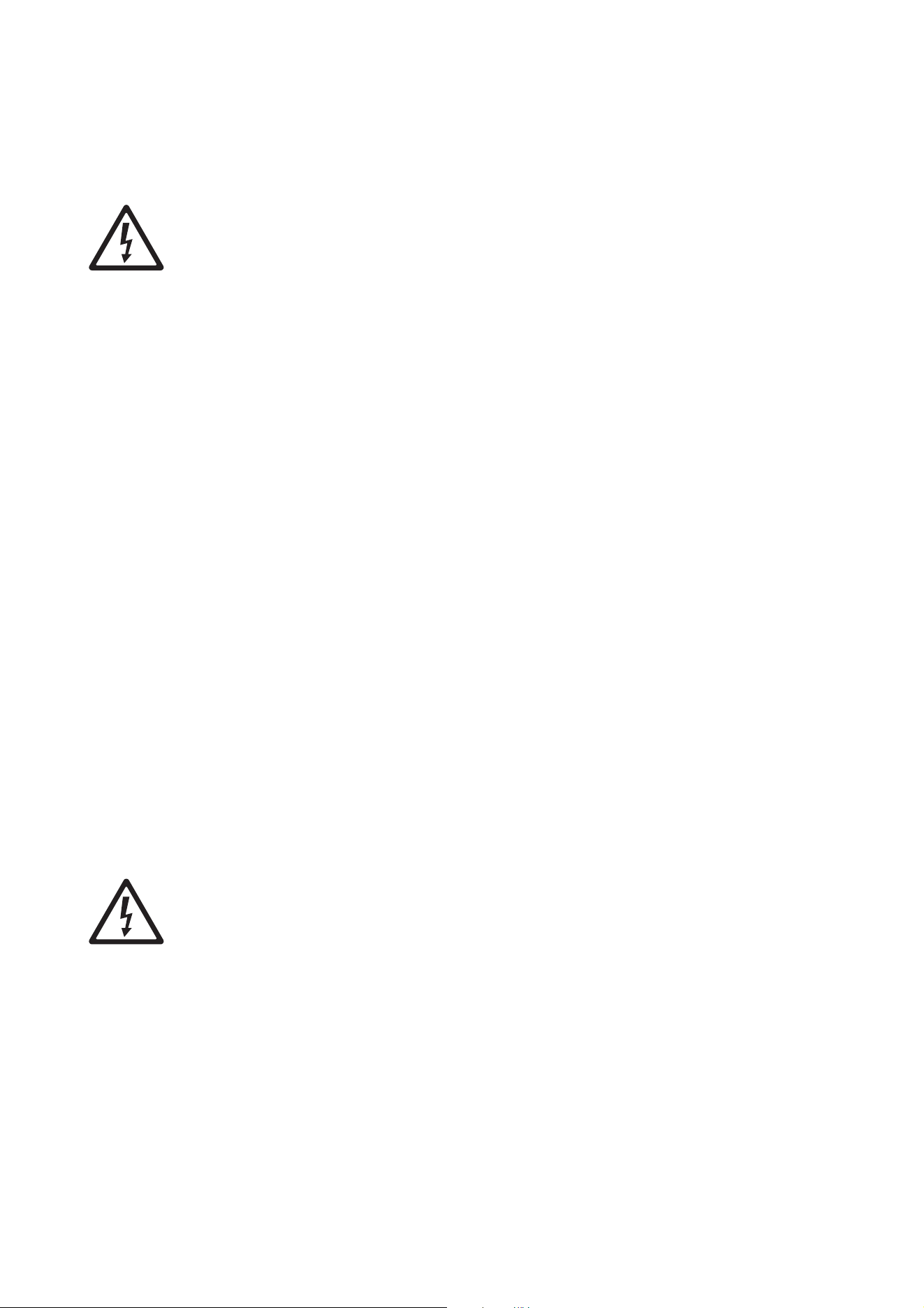
2. See Figure 21. Remove the front cover
screws and front cover with its seal.
3. Loosen the two diffuser retaining clips on the
inner side of the front cover.
4. Slide in the new filter so that the matt,
textured side will face towards the LEDs, and
the shiny side will face towards the front
glass.
5. Make sure that the edges of the diffuser
locate under the diffuser retaining clips, then
tighten the clips so that the filter is pressed
flat against the front glass.
6. Reinstall the front cover as follows:
a. Read“Managing humidity” on page 7.
b. Check that the seal is in perfect condition.
c. Place the seal and cover in position and
drive the cover screws until they are
finger-tight only.
d. Cross-tighten the screws evenly in a
diagonal pattern, increasing torque
gradually in stages to a maximum torque
of 8 Nm (5.9 ft.-lbs.). See example tightening order in Figure 21. Do not over-tighten, or the front
glass may break.
7. Reapply power.
Figure 21: Front cover screws and seal
1
2
3
4
7
8
6
5
Figure 22: Installing a diffuser filter
Matt, textured side
towards LEDs, shiny side
towards glass
Narrow
Medium
Wide
Diffuser retaining clip
28 Exterior 400 Range user manual
Fuse replacement
DANGER! Lock out power to the entire distribution system before servicing or opening any
cover. Replace fuses with ones of the same type and rating only.
Primary fuse
Exterior 400 Range fixtures are protected by a 2.5 amp slow-blow primary fuse located on the power PCB.
If a fixture is completely dead, the primary fuse may have blown.
To replace the primary fuse:
1. Isolate the fixture from power and allow to cool for 20 minutes.
2. Open the rear cover (see Figure 8 on page 13).
3. Replace a defective fuse with one of the same type and rating only. Replacement primary fuses are
available from Martin suppliers (P/N 05020010).
4. Reinstall the rear cover as follows:
a. Read“Managing humidity” on page 7.
b. Check that the seal is in perfect condition.
c. Place the seal and cover in position and drive the cover screws until they are finger-tight only.
d. Cross-tighten the screws evenly in a diagonal pattern, increasing torque gradually in stages to a
maximum torque of 8 Nm (5.9 ft.-lbs.).
5. Reapply power.
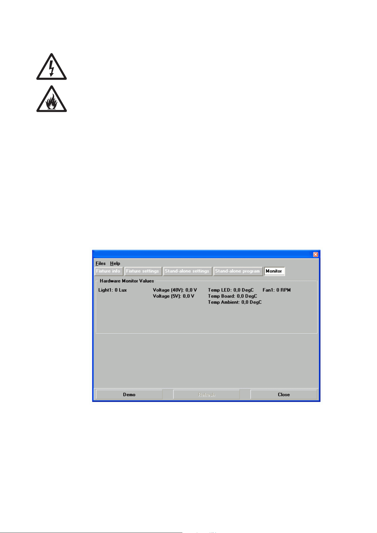
Fixture readouts in MUM
Various types of data can be displayed by connecting a PC as described in "Connecting a PC with MUM" on
page 17 and clicking on the Monitor button:
Light1 displays the light level currently measured by light sensor 1 on the back of the fixture.
Voltag e displays the current voltage in 48 V and 5 V circuits on the main PCB (this data is for service
purposes).
Temp displays the current temperature on the LED circuit board that gives the highest reading, the current
main PCB temperature and the current ambient temperature.
Fan1 displays the current cooling fan speed in RPM (revolutions per minute).
Service and maintenance 29
Software installation
It may be necessary to upload new software (i.e. firmware) to an Exterior 400 Range fixture if you believe
that the product has a software-related fault or if you want to update to a newer version. Software updates
are available from the Martin website (http://www.martin.com) and can be installed via the DMX data link
with the following items:
• The Martin Uploader application, version 5.0 or later, downloadable free of charge from the Support area
of the Martin website.
• The fixture’s main CPU software update file, downloadable free of charge from the Support area of the
Martin website (this file can be downloaded automatically from within the Martin Uploader application)
• A Martin Universal USB-DMX Interface or similar PC/fixture hardware interface and a Windows PC (if you
have a Martin MP-2 Uploader device, it can also be used).
Installing software: normal method
1. Connect the uploader hardware to a Exterior 400 Range fixture’s data input connector. The software will
be uploaded to that fixture and all fixtures of the same type that are powered on and connected via the
DMX link.
2. Upload the fixture software as described in the uploader’s help file or user documentation.
3. Disconnect the uploader hardware and reconnect the fixture to the DMX link.
4. Cycle power off and on. Check that the fixture resets correctly. If an error message appears in the
display, cycle power off and on again and check that the fixture now resets correctly.
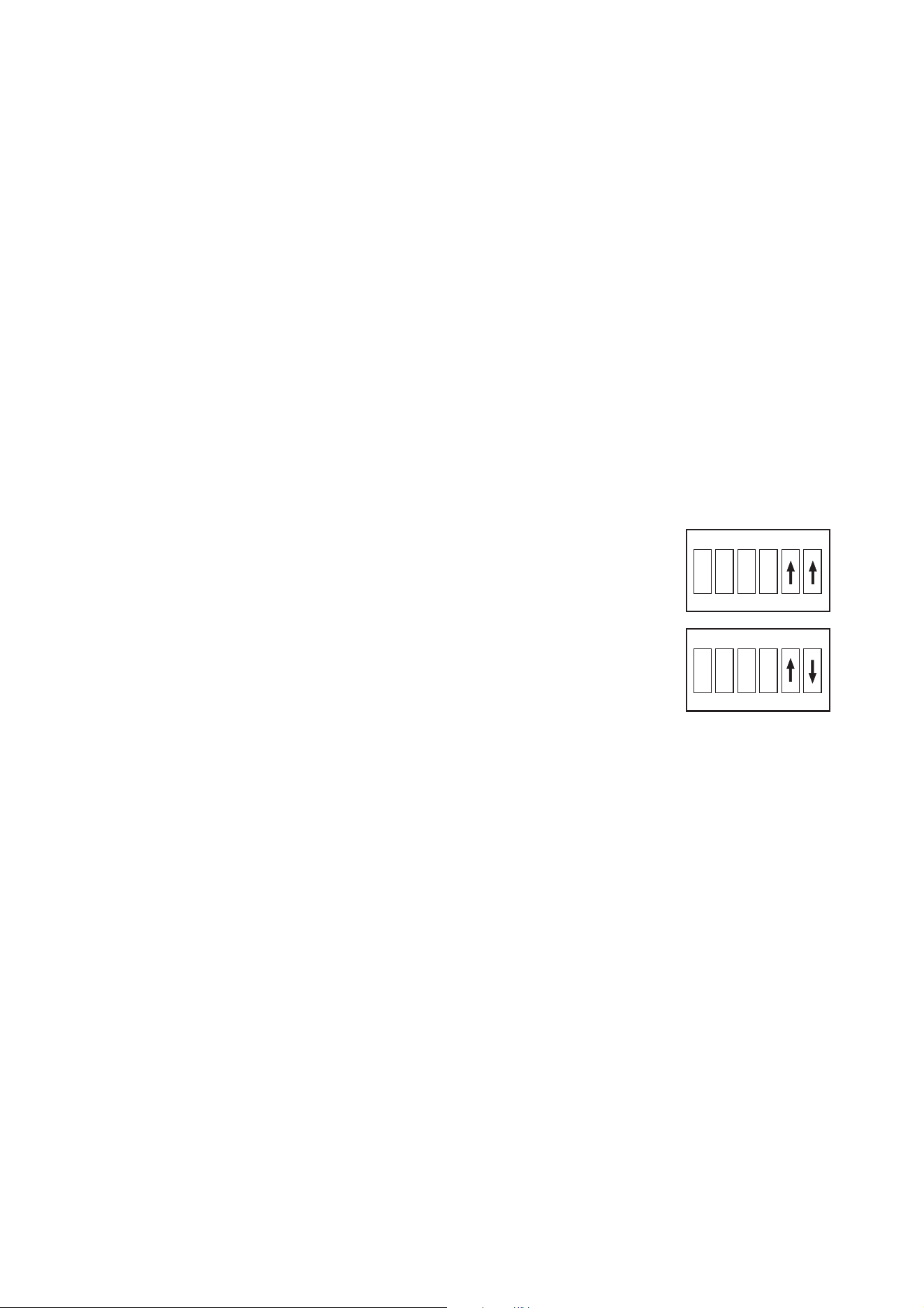
Installing software: boot mode upload
A boot mode upload may be required if the
software update notes call for it or if the
fixture software is seriously corrupted and
the fixture will not accept a software upload
using the normal method described above.
To carry out a boot mode upload:
1. Isolate the fixture from power and allow
to cool for at least 20 minutes.
2. Open the rear cover (see Figure 8 on
page 13).
3. Locate the DIP switch on the main PCB
and move pin 6 to OFF.
4. Reinstall the rear cover seal and the rear cover temporarily.
5. Reapply power and perform the upload as described above.
6. Isolate from power, open the rear cover and move DIP pin 6 back to ON.
7. Reinstall the rear cover as follows:
a. Check that the seal is in perfect condition.
b. Place the seal and cover in position and drive the cover screws until they are finger-tight only.
c. Cross-tighten the screws evenly in a diagonal pattern, increasing torque gradually in stages to a
maximum torque of 8 Nm (5.9 ft.-lbs.).
8. Reapply power.
9. Check that the fixture resets correctly. If an error occurs, cycle power off and on again and check that the
fixture now resets correctly.
1 2 3 4 5 6
DIP switch setting for boot
mode upload
ON
Normal DIP switch setting
1 2 3 4 5 6
ON
Details corrected in manual Rev. D
30 Exterior 400 Range user manual
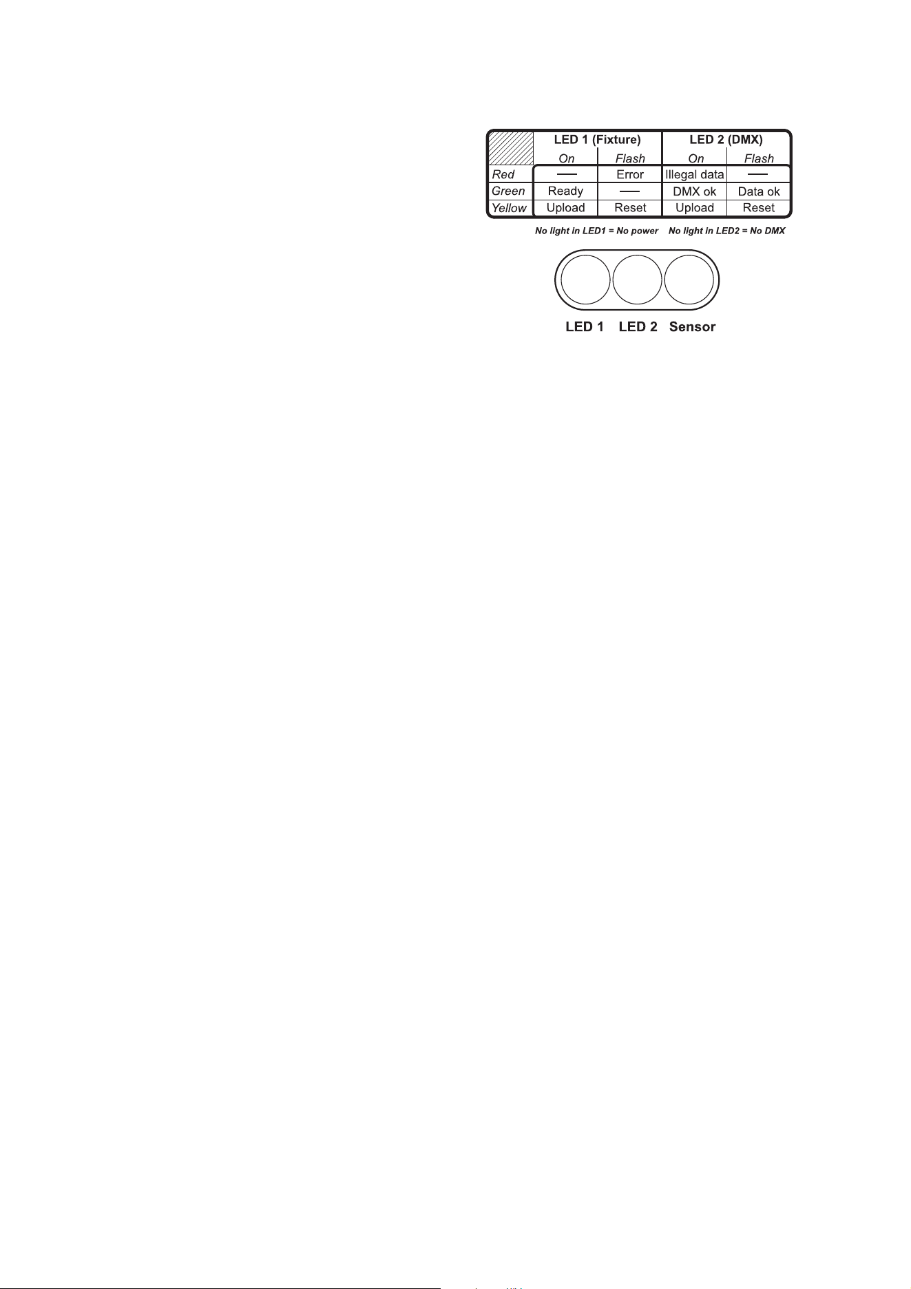
Status indicators
Two LEDs on the rear cover give information
about fixture status.
LED 1 (Fixture status)
• Flashes red if an error occurs that requires
service intervention.
• Lights steady green when the fixture is ready
for operation.
• Lights steady yellow during a software
upload.
• Flashes yellow while the fixture is resetting.
LED 2 (DMX status)
• Lights steady red if the fixture receives data it
cannot recognize.
• Lights steady green when the fixture is successfully receiving a DMX signal.
• Flashes green when the fixture is successfully receiving a data signal.
• Lights steady yellow during a software upload.
• Flashes yellow while the fixture is resetting.
DMX protocols 31
DMX protocols
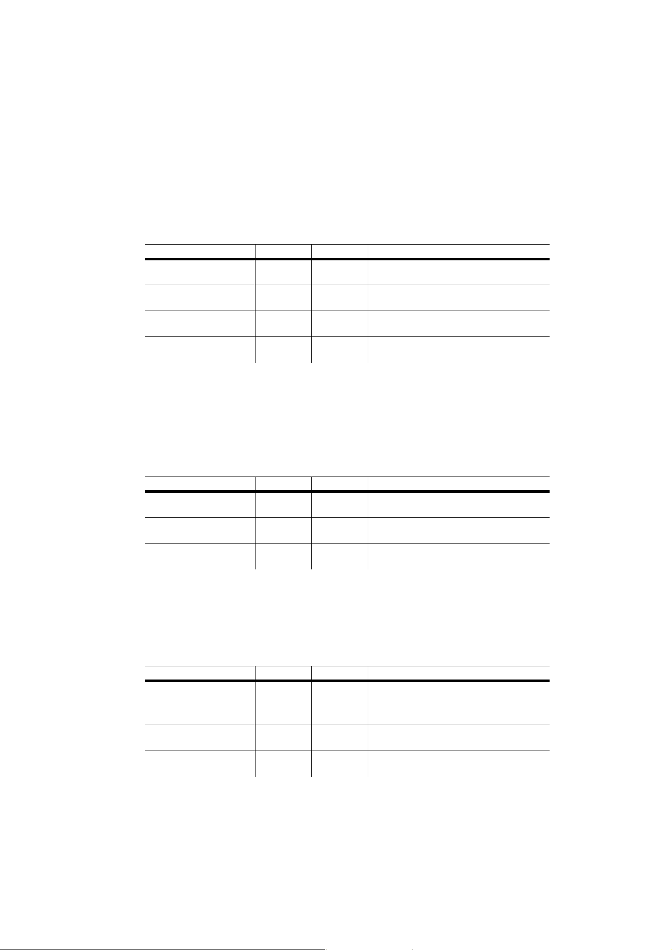
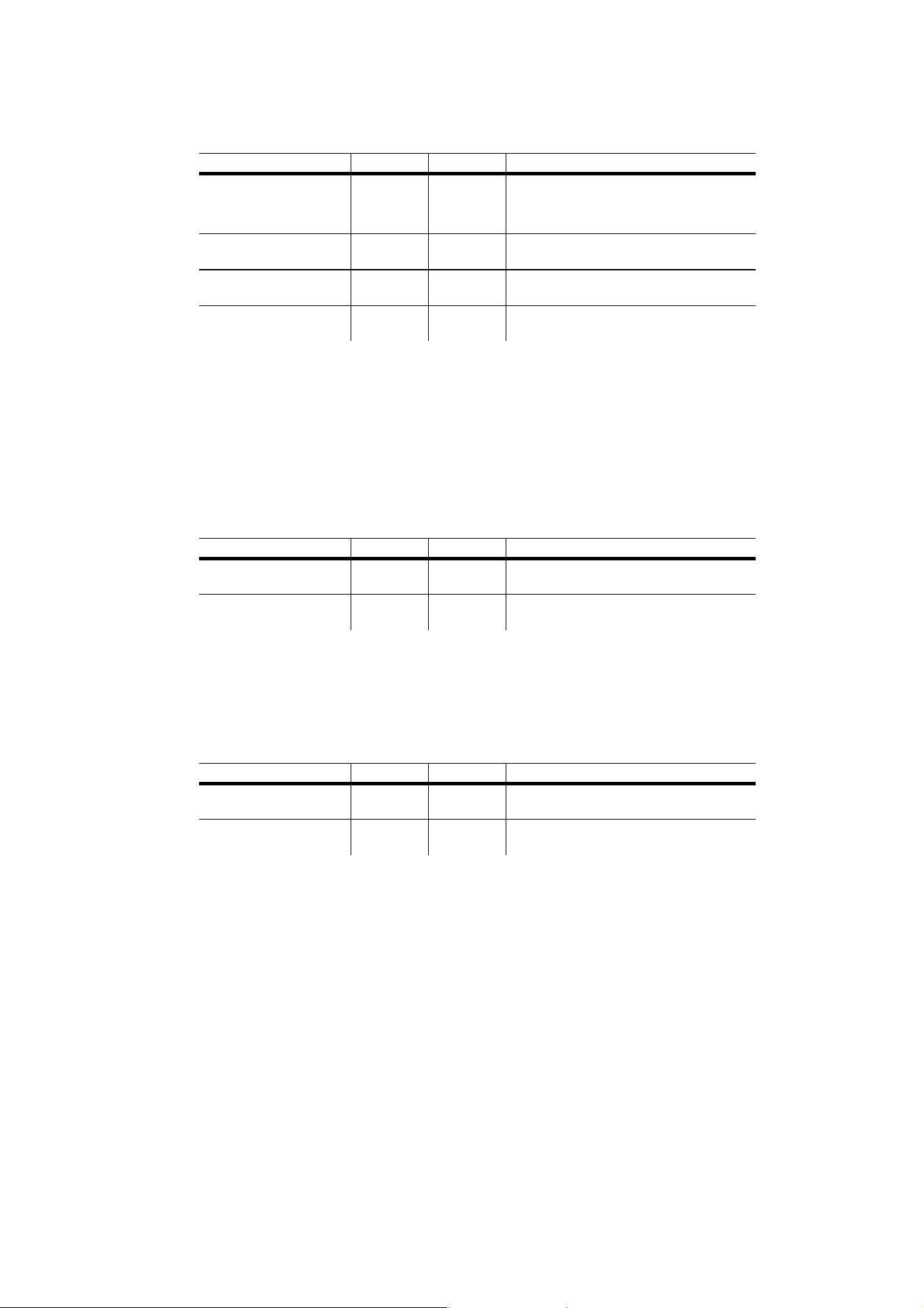
Exterior 400, Exterior 410
RAW mode, uncalibrated
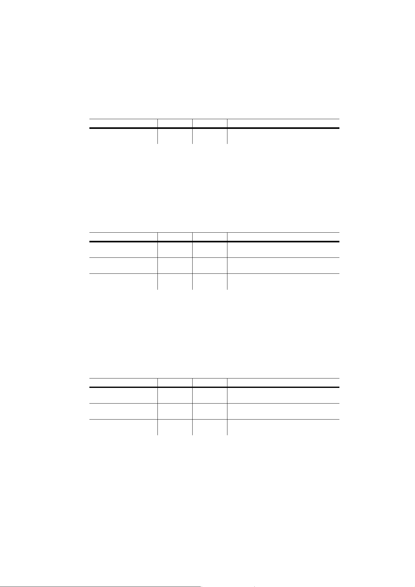
RGB mode, calibrated
All LEDs – including white – can be activated to obtain the calibrated target color at maximum intensity.
HSI mode, calibrated
Start code = 0
Channel Value Percent Function
1
0 - 255 0 - 100
Red
Intensity 0 →100%
2
0 - 255 0 - 100
Green
Intensity 0
→100%
3
0 - 255 0 - 100
Blue
Intensity 0 →100%
4
0 - 255 0 - 100
White
Intensity 0 →100%
Start code = 0
Channel Value Percent Function
1
0 - 255 0 - 100
Red
Intensity 0 →100%
2
0 - 255 0 - 100
Green
Intensity 0 →100%
3
0 - 255 0 - 100
Blue
Intensity 0
→100%
Start code = 0
Channel Value Percent Function
1
0 - 255 0 - 100
Hue
Red → Orange → Ye l l ow → Green →
Cyan → Blue → Indigo → Violet →
Magenta
→ Red
2
0 - 255 0 - 100
Saturation
Zero (white) → Full
3
0 - 255 0 - 100
Intensity
Intensity 0 →100%
32 Exterior 400 Range user manual
HSIC mode, calibrated
Exterior 420
RAW mode, uncalibrated
CT mode, calibrated
Start code = 0
Channel Value Percent Function
1
0 - 255 0 - 100
Hue
Red
→ Orange → Ye l l ow → Green →
Cyan → Blue → Indigo → Violet →
Magenta → Red
2
0 - 255 0 - 100
Saturation
Zero (white)
→ Full saturation
3
0 - 255 0 - 100
Intensity
Intensity 0 →100%
4
0 - 255 0 - 100
Color Temperature Control
Warm → cold
Start code = 0
Channel Value Percent Function
1
0 - 255 0 - 100
Warm white
Intensity 0 →100%
2
0 - 255 0 - 100
Cold white
Intensity 0
→100%
Start code = 0
Channel Value Percent Function
1
0 - 255 0 - 100
Intensity
Intensity 0 →100%
2
0 - 255 0 - 100
Color temperature control
2700 → 6500 K
DMX protocols 33
Exterior 430
I (Intensity) mode (red, green, blue, warm white and cold white fixtures)
Red, green and blue fixtures are calibrated if Color Gamut is set to Exterior 400 Range and uncalibrated if
Color Gamut is set to Fixture.
Cold white and warm white fixtures are uncalibrated and Color Gamut is disabled.
RGB mode (red, green and blue fixtures only)
Red, green and blue fixtures are calibrated if Color Gamut is set to Exterior 400 Range, uncalibrated if
Color Gamut is set to Fixture.
The main fixture color is dominant, the two auxiliary colors are intended for fine-tuning the main color.
HSI mode (red, green and blue fixtures only)
Red, green and blue fixtures are calibrated if Color Gamut is set to Exterior 400 Range, uncalibrated if
Color Gamut is set to Fixture.
The main fixture color is dominant, the two auxiliary colors are intended for fine-tuning the main color hue.
Start code = 0
Channel Value Percent Function
1
0 - 255 0 - 100%
Single color
Intensity 0
→100%
Start code = 0
Channel Value Percent Function
1
0 - 255 0 - 100
Red
Intensity 0 →100%
2
0 - 255 0 - 100
Green
Intensity 0
→100%
3
0 - 255 0 - 100
Blue
Intensity 0 →100%
Start code = 0
Channel Value Percent Function
1
0 - 255 0 - 100
Hue
Variable within color fine-tuning range
2
0 - 255 0 - 100
Saturation
Variable 0
→100%
3
0 - 255 0 - 100
Intensity
Variable 0
→100%
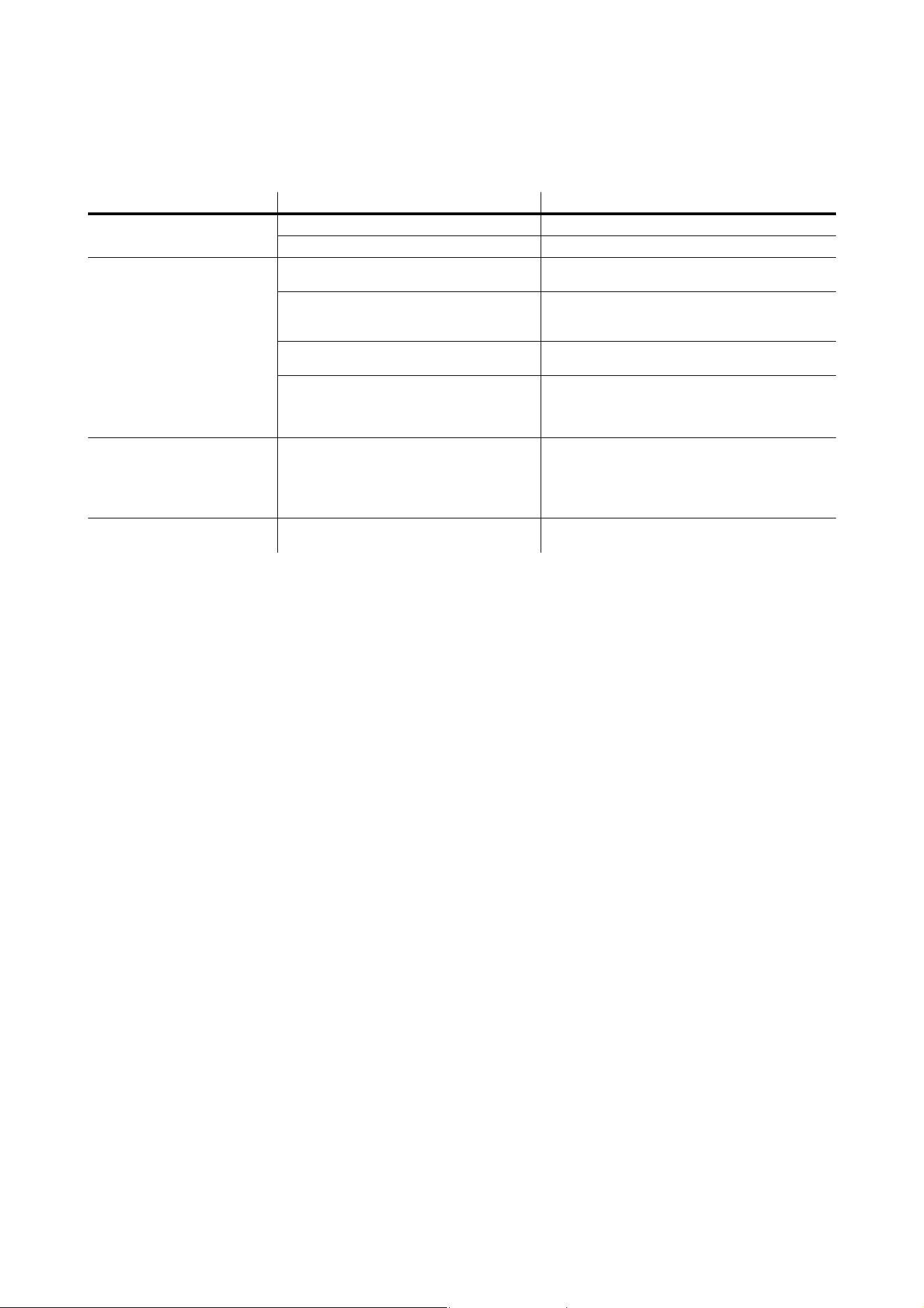
34 Exterior 400 Range user manual
Troubleshooting
Problem Probable cause(s) Remedy
Fixture is completely dead.
No power to fixture. Check power and connections.
Primary fuse blown. Isolate fixture from power. Check fuse and replace.
One or more fixtures responds
incorrectly to control or does not
respond at all.
Fault on DMX link.
Inspect connections and cables. Correct poor
connections. Repair or replace damaged cables.
Incorrect fixture addressing.
Check fixture is set to correct DMX mode.
Check number of channels required by fixture’s
DMX mode and check fixture addresses.
Fixture defective.
Have faulty fixture serviced by Martin service
technician.
Other device on DMX link defective.
Bypass devices on DMX link until the faulty device
has been identified.
Have faulty device tested and serviced by Martin
service technician or device supplier.
LEDs cut out intermittently. Fixture is too hot.
Ensure free airflow around fixture.
Clean fixture.
Check that ambient temperature does not exceed
maximum permitted level.
Contact Martin for service.
LEDs give uneven color from
fixture type to fixture type.
One or more fixtures set to Fixture color
gamut.
Set all fixtures to Exterior 400 Range color gamut
with Martin MUM application.
Table 2: Troubleshooting

Specifications 35
Specifications
Physical
Length . . . . . . . . . . . . . . . . . . . . . . . . . . . . . . . . . . . . . . . . . . . . . . . 169 mm (6.7 in.) including cable gland
Width . . . . . . . . . . . . . . . . . . . . . . . . . . . . . . . . . . . . . . . . . . . . . . . . . . . . . . . . . . . . . . . . .307 mm (12.1 in.)
Height . . . . . . . . . . . . . . . . . . . . . . . . . . . . . . . . . . . . . . . . . . . . . . . . . . . . . . . . . . . . . . . .401 mm (15.8 in.)
Weight . . . . . . . . . . . . . . . . . . . . . . . . . . . . . . . . . . . . . . . . . . . . . . . . . . 7.6 kg (16.8 lbs.) including bracket
Supplied power cable external diameter . . . . . . . . . . . . . . . . . . . . . . . . . . . . . . . . . . . . . . 9.5 mm (0.37 in.)
Supplied data cable external diameter. . . . . . . . . . . . . . . . . . . . . . . . . . . . . . . . . . . . . . . . 6.5 mm (0.25 in.)
Dynamic Effects
Exterior 400, Exterior 410
Color mixing. . . . . . . . . . . . . . . . . . . . . . . . . . . . . . . . . . . . . . . . . . . . . . . . . . . . . . . . . . . . . . . . . . . . RGBW
Red . . . . . . . . . . . . . . . . . . . . . . . . . . . . . . . . . . . . . . . . . . . . . . . . . . . . . . . . . . . . . . . . . . . . . . . . .0 - 100%
Green. . . . . . . . . . . . . . . . . . . . . . . . . . . . . . . . . . . . . . . . . . . . . . . . . . . . . . . . . . . . . . . . . . . . . . . .0 - 100%
Blue . . . . . . . . . . . . . . . . . . . . . . . . . . . . . . . . . . . . . . . . . . . . . . . . . . . . . . . . . . . . . . . . . . . . . . . . .0 - 100%
White . . . . . . . . . . . . . . . . . . . . . . . . . . . . . . . . . . . . . . . . . . . . . . . . . . . . . . . . . . . . . . . . . . . . . . . .0 - 100%
Exterior 420
Color temperature control . . . . . . . . . . . . . . . . . . . . . . . . . . . . . . . . . . . . . . . . . . . . . . . . . . . 2700 - 6500 K
Warm white (2700 K in Calibrated mode) . . . . . . . . . . . . . . . . . . . . . . . . . . . . . . . . . . . . . . . . . . . .0 - 100%
Cold white (6500 K in Calibrated mode) . . . . . . . . . . . . . . . . . . . . . . . . . . . . . . . . . . . . . . . . . . . . .0 - 100%
Exterior 430
All Exterior 430 fixtures
Red, green. blue, warm white (2700 K) or cold white (6500 K) depending on model . . . . . . . . . . .0 - 100%
Red, green and blue fixtures only
Red, green or blue depending on model . . . . . . . . . . . . . . . . . . . . . . . . . . . . . . . . . Single color fine-tuning
Control and Programming
Exterior 400, Exterior 410
Color control modes. . . . . . . . . . . . . . . . . . . . . . . . . . . . . . . . . . . . . . . . . . . . . . . . . .RAW, RGB, HSI, HSIC
DMX channels . . . . . . . . . . . . . . . . . . . . . . . . . . . . . . . . . . . . . . . . . . . . . . . . . . . . . . . . . . . . . . . . . . . 3 or 4
Exterior 420
Color temperature control modes . . . . . . . . . . . . . . . . . . . . . . . . . . . . . . . . . . . . . . . . . . . . . . . . RAW, CTC
DMX channels . . . . . . . . . . . . . . . . . . . . . . . . . . . . . . . . . . . . . . . . . . . . . . . . . . . . . . . . . . . . . . . . . . . . . . .2
Exterior 430
Control modes . . . . . . . . . I, RGB, HSI (RGB and HSI allow color fine-tuning on red, green & blue models)
DMX channels . . . . . . . . . . . . . . . . . . . . . . . . . . . . . . . . . . . . . . . . . . . . . . . . . . . . . . . . . . . . . . . . . . . 1 or 3
Exterior 400 Range (Exterior 400, 410, 420 & 430)
C
ontrol options. . . . . . . . . . . . . . . . . . . . . . . . . . . . . . . . . . DMX, stand-alone, synchronized (master/client)
DMX address setting and setup. . . . . . . . . . PC with Martin MUM software and DABS1 hardware interface
Stand-alone trigger options . . . . . . . . . . . . . . . . . . . . . . . . . . . . . . . Internal timer and/or ambient light level
Stan
d-alone and master/client programming . . . . . . . . . . . . . . . PC with Martin MUM software and DABS1
Protocol . . . . . . . . . . . . . . . . . . . . . . . . . . . . . . . . . . . . . . . . . . . . . . . . . . . . . . . . . . . . . . USITT DMX512-A
Receiver. . . . . . . . . . . . . . . . . . . . . . . . . . . . . . . . . . . . . . . . . . . . . . . . . . . . . . . . . . . . . . . . . . . . . . .RS-485
Firmware update . . . . . . . . . . . . . . . . . . . . . . . . . . . . . . . . . . . . . . . . . . . . . . . . . Serial upload via DMX link
Photometric Data
Light source . . . . . . . . . . . . . . . Exterior 410 = Cree MC-E; other fixtures = Cree XP-E high power emitters
Half-peak angle . . . . . . . . . . . . . . . . . . . . . . . . . . . . . . . . . . . . . . . . . . . . . . . . . . . . 21° with narrow diffuser
Construction
Color . . . . . . . . . . . . . . . . . . . . . . . . . . . . . . . . . . . . . . . . . . . . . . . . . . . . . . . Clear anodized, white or black
Housing . . . . . . . . . . . . . . . . . . . . . . . . . . . . . . . . . . . . . . . . . . . . . . . . . . . . . . . . . . . . . Anodized aluminum
Mounting bracket . . . . . . . . . . . . . . . . . . . . . . . . . . . . . . . . . . . . . . . . . . .8 mm (0.3 in.) anodized aluminum
Front glass . . . . . . . . . . . . . . . . . . . . . . . . . . . . . . . . . . . . . . . . . . . . . . 6 mm (0.2 in.) anti-reflection coated
Protection rating. . . . . . . . . . . . . . . . . . . . . . . . . . . . . . . . . . . . . . . . . . . . . . . . . . . . . . . . . . . . . . . . . . .IP 65

Installation
Orientation . . . . . . . . . . . . . . . . . . . . . . . . . . . . . . . . . . . . . . . . . . . . . . . . . . . . . . . . . . . . . . . . . . . . . . . .Any
Mounting . . . . . . . . . . . . . . . . . . . . . . . . . . . . Flat surface at any angle, pedestal or other suitable support
Vertical aiming . . . . . . . . . . . . . . . . . . . . . . . . . . . . . . . . . . . . . . . . . . . . . . . . . . . . . . . . . . . . . . . . . . . . 330°
Minimum distance to illuminated surfaces . . . . . . . . . . . . . . . . . . . . . . . . . . . . . . . . . . . . . . 0.1 m (4 inches)
Connections
Power cable entry . . . . . . . . . . . . . . . . . . . . . . . . . . . . . . . . . . . . . . . . . . . . . . . . . . . . . . . IP68 cable gland
Power connection. . . . . . . . . . . . . . . . . . . . . . . . . . . . . . . . . . . . . . . . . . . . . . . . . . . 1.8 m (5.9 ft.) cable tail
Data cable entry. . . . . . . . . . . . . . . . . . . . . . . . . . . . . . . . . . . . . . . . . . . . . . . . . . . . . . . . . IP68 cable gland
Data connection. . . . . . . . . . . . . . . . . . . . . . . . . . . . . . . . .1.8 m (5.9 ft.) combined input + output cable tail
Electrical
AC power . . . . . . . . . . . . . . . . . . . . . . . . . . . . . . . . . . . . . . . . . . . . . . . . . . . . 100-240 V nominal, 50/60 Hz
Power supply unit. . . . . . . . . . . . . . . . . . . . . . . . . . . . . . . . . . . . . . . . Integrated, auto-sensing multi-voltage
Main fuse . . . . . . . . . . . . . . . . . . . . . . . . . . . . . . . . . . . . . . . . . . . . . . . . . . . . . . . . . . . . . 2.5 AT (slow blow)
Typical power and current
100 V, 50 Hz. . . . . . . . . . . . . . . . . . . . . . . . . . . . . . . . . . . . . . . . . . . . . . . . . . . . . .139 W, 1.4 A, PF = 0.990
100 V, 60 Hz. . . . . . . . . . . . . . . . . . . . . . . . . . . . . . . . . . . . . . . . . . . . . . . . . . . . . .139 W, 1.4 A, PF = 0.989
110 V, 60 Hz. . . . . . . . . . . . . . . . . . . . . . . . . . . . . . . . . . . . . . . . . . . . . . . . . . . . . .137 W, 1.3 A, PF = 0.988
120 V, 60 Hz. . . . . . . . . . . . . . . . . . . . . . . . . . . . . . . . . . . . . . . . . . . . . . . . . . . . . .136 W, 1.2 A, PF = 0.986
208 V, 60 Hz. . . . . . . . . . . . . . . . . . . . . . . . . . . . . . . . . . . . . . . . . . . . . . . . . . . . . .133 W, 0.7 A, PF = 0.932
230 V, 50 Hz. . . . . . . . . . . . . . . . . . . . . . . . . . . . . . . . . . . . . . . . . . . . . . . . . . . . . .132 W, 0.7 A, PF = 0.925
240 V, 50 Hz. . . . . . . . . . . . . . . . . . . . . . . . . . . . . . . . . . . . . . . . . . . . . . . . . . . . . .131 W, 0.7 A, PF = 0.886
Measurements made at nominal voltage with all LEDs at full intensity. Allow for a deviation of +/- 10%.
Thermal
Cooling. . . . . . . . . . . . . . . . . . . . . . . . . . . . . . . . . . . . . . . . . . . . . . . . . . . . . . . . . . . . . . . . . . . . . Convection
Maximum ambient temperature (Ta max.) . . . . . . . . . . . . . . . . . . . . . . . . . . . . . . . . . . . . . . . 45° C (113° F)
Minimum ambient temperature (Ta min.) . . . . . . . . . . . . . . . . . . . . . . . . . . . . . . . . . . . . . . . . -30° C (-22° F)
Maximum surface temperature, steady state, Ta=40° C . . . . . . . . . . . . . . . . . . . . . . . . . . . . 90° C (194° F)
Total heat dissipation (calculated, +/- 10%) . . . . . . . . . . . . . . . . . . . . . . . . . . . . . . . . . . . . . . . . 860 BTU/hr.
Approvals
EU safety . . . . . . . . . . . . . . . . . . . . . . . . . . . . . . . . . . . . . . . EN 60598-2-5 (EN 60598-1), IEC/EN 60825-1
EU EMC. . . . . . . . . . . . . . . . . . . . . . . . . . . . . . . . EN 55103-1, EN 55103-2, EN 61000-3-2, EN 61000-3-3
US safety (US models) . . . . . . . . . . . . . . . . . . . . . . . . . . . . . . . . . . . . . . . . . . . . . . . . . . . . . . . . . . UL 1598
Canadian safety (US models) . . . . . . . . . . . . . . . . . . . . . . . . . . . . . . . . . . . . . . . CAN/CSA C.22.2 No. 250
Australia/NZ . . . . . . . . . . . . . . . . . . . . . . . . . . . . . . . . . . . . . . . . . . . . . . . . . . . . . . . . . . . . . . C-TICK N4241
Included Items
Adjustable mounting yoke
Narrow, medium and wide diffusers
Power cable tail, 1.8 m (5 ft. 10 in.), Ø 9.5 mm (0.37 in.), installed
Data cable tail, 1.8 m (5 ft. 10 in.), Ø 6.5 mm (0.25 in.), installed
Accessories
Exterior 200/400 extended mounting yoke . . . . . . . . . . . . . . . . . . . . . . . . . . . . . . . . . . . . . . P/N 21080030
Exterior 200/400 floor stand. . . . . . . . . . . . . . . . . . . . . . . . . . . . . . . . . . . . . . . . . . . . . . . . . . P/N 91611305
Safety eyebolt . . . . . . . . . . . . . . . . . . . . . . . . . . . . . . . . . . . . . . . . . . . . . . . . . . . . . . . . . . . . P/N 91611239
Narrow beam angle kit (diffuser) . . . . . . . . . . . . . . . . . . . . . . . . . . . . . . . . . . . . . . . . . . . . . . P/N 41600122
Medium beam angle kit (diffuser) . . . . . . . . . . . . . . . . . . . . . . . . . . . . . . . . . . . . . . . . . . . . . P/N 41600123
Wide beam angle kit (diffuser) . . . . . . . . . . . . . . . . . . . . . . . . . . . . . . . . . . . . . . . . . . . . . . . . P/N 41600124
3-pin male XLR connector, cable-type, IP65 . . . . . . . . . . . . . . . . . . . . . . . . . . . . . . . . . . . . . P/N 91611306
3-pin female XLR connector, cable-type, IP65. . . . . . . . . . . . . . . . . . . . . . . . . . . . . . . . . . . . P/N 91611307
Spare parts
2.5 AT main fuse . . . . . . . . . . . . . . . . . . . . . . . . . . . . . . . . . . . . . . . . . . . . . . . . . . . . . . . . . . P/N 05020010
Related items
Martin DABS1™ USB-DMX Hardware Interface . . . . . . . . . . . . . . . . . . . . . . . . . . . . . . . . . . P/N 90758090
Martin USB Tools™ package including MUM™ application . . . . . . . Free download from www.martin.com

Ordering Information
Exterior 400™
Exterior 400 EU model (aluminum) . . . . . . . . . . . . . . . . . . . . . . . . . . . . . . . . . . . . . . . . . . . . P/N 90545050
Exterior 400 US model (aluminum) . . . . . . . . . . . . . . . . . . . . . . . . . . . . . . . . . . . . . . . . . . . . P/N 90545150
Exterior 400 EU model (black) . . . . . . . . . . . . . . . . . . . . . . . . . . . . . . . . . . . . . . . . . . . . . . . . P/N 90545060
Exterior 400 US model (black) . . . . . . . . . . . . . . . . . . . . . . . . . . . . . . . . . . . . . . . . . . . . . . . . P/N 90545160
Exterior 400 EU model (white). . . . . . . . . . . . . . . . . . . . . . . . . . . . . . . . . . . . . . . . . . . . . . . . P/N 90545070
Exterior 400 US model (white). . . . . . . . . . . . . . . . . . . . . . . . . . . . . . . . . . . . . . . . . . . . . . . . P/N 90545170
Exterior 410™
Exterior 410 EU model (aluminum) . . . . . . . . . . . . . . . . . . . . . . . . . . . . . . . . . . . . . . . . . . . . P/N 90545053
Exterior 410 US model (aluminum) . . . . . . . . . . . . . . . . . . . . . . . . . . . . . . . . . . . . . . . . . . . . P/N 90545151
Exterior 410 EU model (black) . . . . . . . . . . . . . . . . . . . . . . . . . . . . . . . . . . . . . . . . . . . . . . . . P/N 90545061
Exterior 410 US model (black) . . . . . . . . . . . . . . . . . . . . . . . . . . . . . . . . . . . . . . . . . . . . . . . . P/N 90545161
Exterior 410 EU model (white). . . . . . . . . . . . . . . . . . . . . . . . . . . . . . . . . . . . . . . . . . . . . . . . P/N 90545071
Exterior 410 US model (white). . . . . . . . . . . . . . . . . . . . . . . . . . . . . . . . . . . . . . . . . . . . . . . . P/N 90545171
Exterior 420™
Exterior 420 EU model (aluminum) . . . . . . . . . . . . . . . . . . . . . . . . . . . . . . . . . . . . . . . . . . . . P/N 90545051
Exterior 420 US model (aluminum) . . . . . . . . . . . . . . . . . . . . . . . . . . . . . . . . . . . . . . . . . . . . P/N 90545152
Exterior 420 EU model (black) . . . . . . . . . . . . . . . . . . . . . . . . . . . . . . . . . . . . . . . . . . . . . . . . P/N 90545062
Exterior 420 US model (black) . . . . . . . . . . . . . . . . . . . . . . . . . . . . . . . . . . . . . . . . . . . . . . . . P/N 90545162
Exterior 420 EU model (white). . . . . . . . . . . . . . . . . . . . . . . . . . . . . . . . . . . . . . . . . . . . . . . . P/N 90545072
Exterior 420 US model (white). . . . . . . . . . . . . . . . . . . . . . . . . . . . . . . . . . . . . . . . . . . . . . . . P/N 90545172
Exterior 430™
Exterior 430 Red, EU Model, Aluminum . . . . . . . . . . . . . . . . . . . . . . . . . . . . . . . . . . . . . . . . P/N 90545052
Exterior 430 Red, US Model, Aluminum . . . . . . . . . . . . . . . . . . . . . . . . . . . . . . . . . . . . . . . . P/N 90545153
Exterior 430 Red, EU Model, Black . . . . . . . . . . . . . . . . . . . . . . . . . . . . . . . . . . . . . . . . . . . . P/N 90545063
Exterior 430 Red, US Model, Black . . . . . . . . . . . . . . . . . . . . . . . . . . . . . . . . . . . . . . . . . . . . P/N 90545163
Exterior 430 Red, EU Model, White. . . . . . . . . . . . . . . . . . . . . . . . . . . . . . . . . . . . . . . . . . . . P/N 90545073
Exterior 430 Red, US Model, White. . . . . . . . . . . . . . . . . . . . . . . . . . . . . . . . . . . . . . . . . . . . P/N 90545173
Exterior 430 Green, EU Model, Aluminum. . . . . . . . . . . . . . . . . . . . . . . . . . . . . . . . . . . . . . . P/N 90545054
Exterior 430 Green, US Model, Aluminum. . . . . . . . . . . . . . . . . . . . . . . . . . . . . . . . . . . . . . . P/N 90545154
Exterior 430 Green, EU Model, Black . . . . . . . . . . . . . . . . . . . . . . . . . . . . . . . . . . . . . . . . . . P/N 90545064
Exterior 430 Green, US Model, Black . . . . . . . . . . . . . . . . . . . . . . . . . . . . . . . . . . . . . . . . . . P/N 90545164
Exterior 430 Green, EU Model, White . . . . . . . . . . . . . . . . . . . . . . . . . . . . . . . . . . . . . . . . . . P/N 90545074
Exterior 430 Green, US Model, White . . . . . . . . . . . . . . . . . . . . . . . . . . . . . . . . . . . . . . . . . . P/N 90545174
Exterior 430 Blue, EU Model, Aluminum . . . . . . . . . . . . . . . . . . . . . . . . . . . . . . . . . . . . . . . . P/N 90545055
Exterior 430 Blue, US Model, Aluminum . . . . . . . . . . . . . . . . . . . . . . . . . . . . . . . . . . . . . . . . P/N 90545155
Exterior 430 Blue, EU Model, Black. . . . . . . . . . . . . . . . . . . . . . . . . . . . . . . . . . . . . . . . . . . . P/N 90545065
Exterior 430 Blue, US Model, Black. . . . . . . . . . . . . . . . . . . . . . . . . . . . . . . . . . . . . . . . . . . . P/N 90545165
Exterior 430 Blue, EU Model, White . . . . . . . . . . . . . . . . . . . . . . . . . . . . . . . . . . . . . . . . . . . P/N 90545075
Exterior 430 Blue, US Model, White . . . . . . . . . . . . . . . . . . . . . . . . . . . . . . . . . . . . . . . . . . . P/N 90545175
Exterior 430 Cold White (6500 K), EU Model, Aluminum . . . . . . . . . . . . . . . . . . . . . . . . . . . P/N 90545056
Exterior 430 Cold White (6500 K), US Model, Aluminum . . . . . . . . . . . . . . . . . . . . . . . . . . . P/N 90545156
Exterior 430 Cold White (6500 K), EU Model, Black . . . . . . . . . . . . . . . . . . . . . . . . . . . . . . . P/N 90545066
Exterior 430 Cold White (6500 K), US Model, Black . . . . . . . . . . . . . . . . . . . . . . . . . . . . . . . P/N 90545166
Exterior 430 Cold White (6500 K), EU Model, White . . . . . . . . . . . . . . . . . . . . . . . . . . . . . . . P/N 90545076
Exterior 430 Cold White (6500 K), US Model, White . . . . . . . . . . . . . . . . . . . . . . . . . . . . . . . P/N 90545176
Exterior 430 Warm White (2700 K), EU Model, Aluminum . . . . . . . . . . . . . . . . . . . . . . . . . . P/N 90545057
Exterior 430 Warm White (2700 K), US Model, Aluminum . . . . . . . . . . . . . . . . . . . . . . . . . . P/N 90545157
Exterior 430 Warm White (2700 K), EU Model, Black . . . . . . . . . . . . . . . . . . . . . . . . . . . . . . P/N 90545067
Exterior 430 Warm White (2700 K), US Model, Black . . . . . . . . . . . . . . . . . . . . . . . . . . . . . . P/N 90545167
Exterior 430 Warm White (2700 K), EU Model, White. . . . . . . . . . . . . . . . . . . . . . . . . . . . . . P/N 90545077
Exterior 430 Warm White (2700 K), US Model, White. . . . . . . . . . . . . . . . . . . . . . . . . . . . . . P/N 90545177
Specifications subject to change without notice.
Data is valid for all models in range except where indicated.
See www.martin.com for latest specifications including full photometric data, LED lifetimes, etc.


www.martin.com • Olof Palmes Allé 18 • 8200 Aarhus N • Denmark
Tel: +45 8740 0000 • Fax +45 8740 0010
