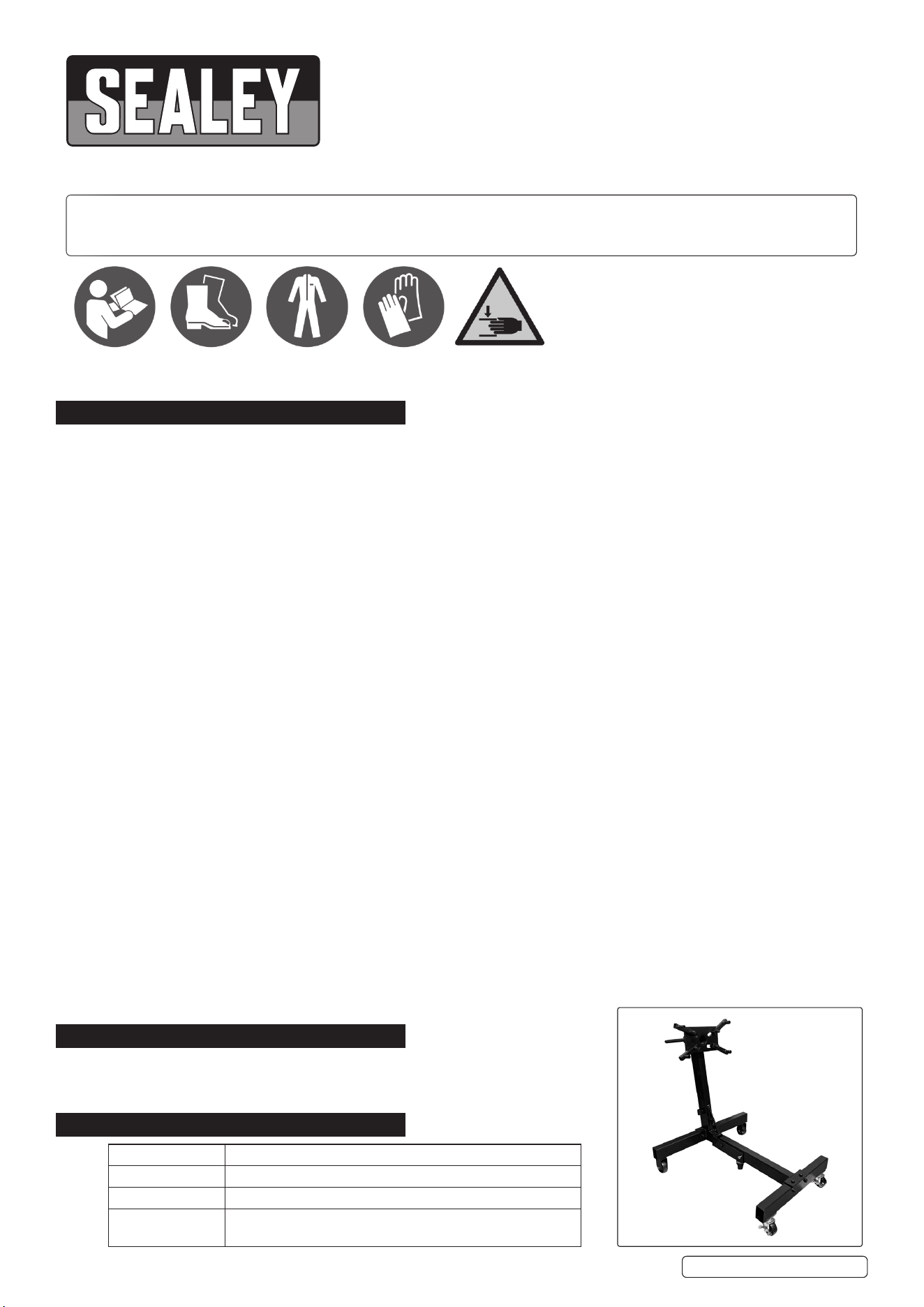
680KG FOLDING ENGINE STAND
Thank you for purchasing a Sealey product. Manufactured to a high standard, this product will, if used according to these
instructions, and properly maintained, give you years of trouble free performance.
IMPORTANT: PLEASE READ THESE INSTRUCTIONS CAREFULLY. NOTE THE SAFE OPERATIONAL REQUIREMENTS, WARNINGS & CAUTIONS. USE
THE PRODUCT CORRECTLY AND WITH CARE FOR THE PURPOSE FOR WHICH IT IS INTENDED. FAILURE TO DO SO MAY CAUSE DAMAGE AND/OR
PERSONAL INJURY AND WILL INVALIDATE THE WARRANTY. KEEP THESE INSTRUCTIONS SAFE FOR FUTURE USE.
1. SAFETY
WARNING! Ensure all Health and Safety, local authority, and general workshop practice regulations are strictly adhered to when using
this equipment.
9 Before using the stand ensure it is in good working order.
9 Ensure the stand legs and arms are locked with respective pins and R clips before use.
9 Replace or repair damaged parts. Use recommended parts only. Unauthorised parts may be dangerous and will invalidate the warranty.
8 DO NOT use unit if damaged.
9 Keep the stand clean for best and safest performance.
9 Use only with legs folded down and pinned.
9 Locate the stand in a suitable work area, keep area clean and tidy and free from unrelated materials. Ensure there is adequate lighting.
9 Use on a rm, level surface capable of sustaining the stand and the load.
9 Maintain correct balance and footing. Ensure the oor is not slippery and wear non-slip shoes.
9 Ensure all non-essential persons keep a safe distance whilst the stand is in use.
9 Lock mounting plate in position with locking pin before xing a load and ensure the load is centred and securely mounted on the
mounting plate.
9 When an engine is mounted, take the weight of the engine on the handle before removing the locking pin.
9 Ensure the stand and load are stable.
9 To move a loaded stand, steady the load and push from behind the main post of the stand so that the castor wheels are ahead of the
load.
8 DO NOT pull the unit backwards, or push from the side, as this may cause the stand to tip.
8 DO NOT concentrate a heavy load to either side or end of the Engine Stand. This can cause the balance to shift suddenly, tipping the
Engine Stand and its load which can quickly cause severe injury and property damage!
9 Ensure surface over which the stand is to travel is strong enough to take the stand and load and that it is not cracked, uneven, sloped
or obstructed.
8 DO NOT allow untrained persons to use the stand.
8 DO NOT exceed the rated capacity of 680kg.
8 DO NOT use to support humans or animals.
8 DO NOT climb on the Engine Stand.
▲ DANGER! DO NOT work under an engine mounted on the stand.
8 DO NOT use the stand for purposes other than those for which it is designed.
9 When not in use store stand in a safe, dry, childproof area.
9 Use extreme caution while rotating the hand crank to rotate the load as a large, top-heavy engine or similar object could result in a
sudden imbalance condition and cause the Engine Stand to suddenly tip.
▲ DANGER! While rotating, always stand behind the crank end of the stand and make constant observations of the casters. If any
indication of instability occurs, STOP IMMEDIATELY!
▲ DANGER! PINCH/CRUSH HAZARD! This Engine Stand has moveable components that can crush and pinch. Keep ngers and hands
away from pinch points when operating.
2. INTRODUCTION
Accepts a wide variety of engines and transmissions. The head swivel 360° for
accessibility to all parts of the engine. Fully adjustable mounting arms. Swivel castors
provide excellent manoeuvrability. Maximum Load Length: 700mm.
3. SPECIFICATION
Original Language Version
© Jack Sealey Limited
Refer to
instructions
Wear protective
gloves
Wear safety
footwear
Wear protective
clothing
Warning:
Pinch crush
hazard
ES680F Issue:1 28/11/24
MODEL NO: ES680F
Model No: ES680F
Capacity: 680kg
Nett Weight: 32.5kg
Size (W x D x H): Unfolded: 1000 x 800 x 1150mm, Folded: 560 x 800 x
1150mm
4. ASSEMBLY
4.1. REFER TO PARTS DIAGRAM
WARNING! The Engine Stand consists of heavy metal components which can cause potentially serious injuries if allowed to drop.
WARNING! Avoid pinching hands while handling parts during assembly.
9 Get the assistance of a helper during assembly.
9 Assemble in a large, uncluttered area close to area of intended usage.
9 Leave xings loose until assembly is complete then tighten.
9 Allow sucient area for operator and helper to remain clear when choosing operating area.
NOTE: To protect the nish of the engine stand components from damage and scratches, use cardboard, carpet, blankets etc. to cover
the area before beginning assembly.
4.2. Assemble Main Post (1) to Side Leg (2) using hex head Bolts M12 x110mm (20), Flat Washer M12 (21) and Spring Washer M12 Zinc
(22), Steel Nut M12 Zinc.
4.3. Assemble the Front Leg (3) to the Side Leg Castor (4), using two Bolts Assemblies M12 x 100 (27), and Bolt Assemblies (28) M12 x 75
as shown.
4.4. Assemble Fixed Wheel (13), and Wheel Bushing (14) to Side Leg, Fixed (2) using Hex Head Set Screw M8 x 15 Zinc (15), as shown.
4.5. Mount the middle caster (30) to the Main Post (1) using Bolt Assembly M16 x 100 (24) and Leg Pin 12 x 90 (25).
4.6. Assemble locking Caster wheel (29) to Side Leg, Caster (4).
4.7. Assemble Front Leg (3) and Side Leg, Caster (4) to the Main Post (1) using Bolt Assembly M16 x 100 (24).
4.8. Insert Head Mounting Plate (5) into housing at top of Main Post (1).
4.9. Attach Side Handle (6) and Locking Pin (7) to Main Post (1).
4.10. Assemble Mounting Arms (8) to Head Mounting Plate (5) using Hex Head Bolt M14 x 65 (9) Flat Washer M14 Zinc (10) Spring Washer
M14 Zinc (11) and Steel Nut M14 Zinc (12).
4.11. Tighten all fasteners and place end caps into the leg ends.
5. OPERATION
WARNING: Ensure that legs are down and secured in the lowered position.
5.1. Only use mounting bolts of the equivalent grade or stronger as those supplied by the vehicle manufacturer to mount an engine,
transmission or other heavy assembly to this stand.
Before applying load lock the mounting plate rotating mechanism.
Using a hoist suspend the engine level with the mounting plate. With the mounting arms loose from the mounting plate (but not
removed) bolt the mounting arms to the rear of the engine using the bell housing mounting bolts (bolts not supplied).
5.1.1. Make sure the engine is centred and straight on the mounting plate, then tighten the mounting arms to the engine and the mounting
arms to the mounting plate. After making sure all connections are tight SLOWLY lower the hoist, transferring the load to the stand.
To remove an engine from the stand rst attach the hoist to the engine using a sling or similar device. After the hoist and sling are
secure to the engine raise the hoist taking the load o the stand. The mounting bolts can be removed freeing the stand from the
engine.
NOTE: While rotating, always stand behind the crank end of the stand and make constant observations of the castors.
WARNING! If any indication of instability occurs, STOP IMMEDIATELY!
WARNING! DO NOT overload. Overloading can cause damage or failure of the stand.
6. STORAGE
6.1. FOLDING UP THE ENGINE STAND
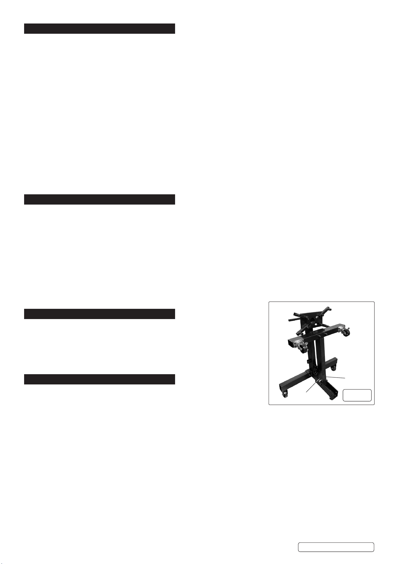
6.1.1. Remove ‘R’ Pin (26) from the Leg Pin and set aside for re-use (see g.1).
6.1.2. Fold the Front leg as shown in g.1.
NOTE: Carefully hold the Engine Stand Post with one hand to prevent it from falling
forward while raising the legs.
6.1.3. When the leg is lifted, x in place by placing the Leg Pin into the hole next to the pivot
point and ret the R Pin (26) (g.1).
7. MAINTENANCE
7.1. Before each use, visual inspection shall be made before each use of the stand checking
for cracks, cracked welds and/or damaged parts, check the tightness of fasteners.
Any stand that appears to be damaged in any way shall be removed from service
immediately.
7.1.1. Keep all moving components of the Engine Stand well lubricated and free of any dirt or debris accumulations.
7.1.2. The Engine Stand is nished in rugged powder coating. However it is advisable to keep the nish clean and free from excessive dust
and dirt.
7.1.3. Keep the Engine Stand in a clean and dry environment. DO NOT store it in, or expose it to, a damp or wet environment.
8 DO NOT use if damaged.
WARNING! Because of the potential hazards associated with the misuse of equipment of this type no modications shall be made to
the product.
Original Language Version
© Jack Sealey Limited
ES680F Issue 1 28/11/24
g.1
R Pin
Leg Pin

Original Language Version
© Jack Sealey Limited
Sealey Group, Kempson Way, Suffolk Business Park, Bury St Edmunds, Suffolk. IP32 7AR
01284 757500 sales@sealey.co.uk www.sealey.co.uk
ENVIRONMENT PROTECTION
Recycle unwanted materials instead of disposing of them as waste. All tools, accessories and packaging should be sorted, taken to
a recycling centre and disposed of in a manner which is compatible with the environment. When the product becomes completely
unserviceable and requires disposal, drain any fluids (if applicable) into approved containers and dispose of the product and fluids
according to local regulations.
Note: It is our policy to continually improve products and as such we reserve the right to alter data, specifications and component parts
without prior notice.
Important: No Liability is accepted for incorrect use of this product.
Warranty: Guarantee is 12 months from purchase date, proof of which is required for any claim.
REGISTER YOUR
PURCHASE HERE
ES680F Issue 1 28/11/23