
MILWAUKEE TOOL CORPORATION
13135 W. LISBON RD., BROOKFIELD, WI 53005
Drwg. 3
10
35 35 37 38 39
40 41 42 43 44
13
8
33 34
11
32
25
31
7
18
8
9
19
12
31
2
32
3
33
34
15
27
14
6
30
20
23
5
21
28
26
17
1
16
7
24
22
29
4
40
42
41
38
39
43
37
35
36
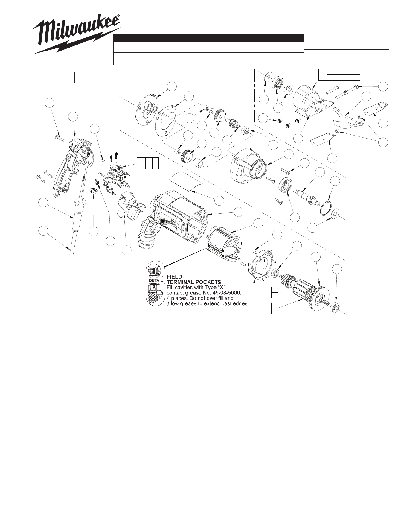
18 GAUGE SHEAR
6852-20
Oct. 2019
FIG. PART NO. DESCRIPTION OF PART NO. REQ.
1 02-04-0640 Ball Bearing (1)
2 02-04-0645 Ball Bearing (1)
3 02-04-0852 Ball Bearing (1)
4 02-04-1229 Ball Bearing (1)
5 02-50-1611 Needle Bearing (1)
6 02-50-2400 Needle Bearing (1)
7 06-82-7275 7-18 x .75 Slotted Plastite T-20 (6)
8 45-30-0035 Slug (1)
9 12-99-2665 Service Nameplate (1)
10 48-08-0500 Shear Head Assy. (Includes 35 thru 44) (1)
11 16-10-2210 Armature Assembly (1)
12 18-07-2206 Field (1)
13 22-18-1210 Brush Card Assembly (1)
14 22-64-6510 Cord Set (1)
15 23-66-2587 Switch (1)
16 28-14-2393 Gearcase (1)
17 28-28-2320 Diaphragm (1)
18 31-15-2010 Handle Halve (1)
19 31-50-2010 Motor Housing (1)
20 32-40-0100 Intermediate Gear (1)
21 32-75-0115 Spindle gear (1)
22 34-80-2300 Retaining Ring (1)
23 36-66-0125 Intermediate Pinion (1)
24 38-50-5753 Spindle (1)
25 42-14-0450 BaeAssembly (1)
26 43-44-0985 Gasket (1)
27 44-76-0210 Cord Protector (1)
28 45-36-1095 Spindle Spacer (1)
29 45-88-0395 Thrust Washer (1)
30 45-88-7990 Thrust Washer (1)
31 45-30-0030 Slug (2)
32 22-84-0845 Fan (1)
33 22-18-1310 Brush Assembly (2)
34 23-52-1610 Brush Spring (2)
35 45-88-7310 Washer (1)
36 43-16-0100 Eccentric Assembly (1)
54-44-0550
58-01-1805
A80A
00
0
EXAMPLE:
Component Parts (Small #)
Are Included When Ordering
The Assembly (Large #).
FIG. PART NO. DESCRIPTION OF PART NO. REQ.
37 43-84-0460 Knurled Insert (3)
38 06-75-2115 10-24 x 1-1/4 Skt. Hd. Cap Screw (3)
39 48-44-0170 Blade - Right Side (1)
40 42-40-0520 Bushing (2)
41 48-44-0150 Blade - Center (1)
42 48-44-0160 Blade - Left Side (1)
43 43-76-0400 Shear Housing (1)
44 49-96-0070 5/32 Hex Allen Wrench (Not Shown) (1)
FIG. LUBRICATION:
16 Place 5 grams (3/16 oz.) of Type "Y" Grease,
No. 49-08-5270 on top of the inserted intermediate ball
bearing (1) and on the intermediate pinion (23). After
inserting the balance of the gearing mechanism (20, 30, 28
and 21), place 13 grams (1/2 oz.) of "Y" Grease at the
armaturepinioncenterlineinthegearcaseandlltothetop
of the intermediate gear (20). Grease must contact at least
25% of the intermediate gear teeth.
36,40,41 During assembly, use a dab of Type "E" Grease,
No.49-08-4122tolubricateats,pivotholeandsidesof
center blade (41), eccentric assembly (36) and bushing (40).
5,6,17 Beforeassembly,lightlycoatallpresstareaswith
lightweight spindle oil.
FIG. NOTES:
5,6,17 Needlebearingstobepressedushto.010underushfrom
theendwhichhasthevendorsidentication.
REVISED BULLETIN DATE
CATALOG NO.
SERVICE PARTS LIST
BULLETIN NO.
SERIAL NUMBER
PREFIX & BREAK
WIRING INSTRUCTION
SPECIFY CATALOG NO. AND SERIAL NO. WHEN ORDERING PARTS
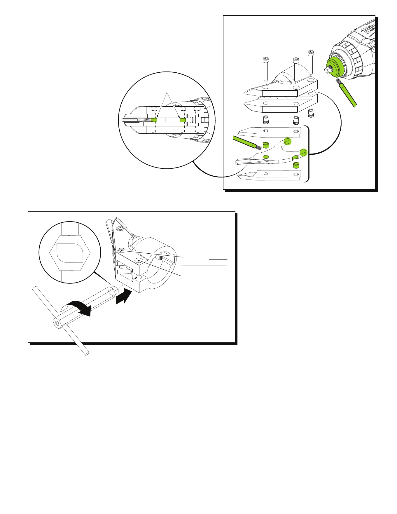
Bottom view of
Shear Head
Assembly
Bushings
When servicing Shear Head Assembly No. 48-08-0500 pay close attention to the
placement of the Bushings. One is to be placed in the hole of the Center Blade
and is to be held in place with the front most screw on the Shear Housing. The
other bushing is to be located below the small concave notch of the Center Blade
and is to be secured with the middle screw on the Shear Housing. Prior to assem-
bly, it is recommended to use Type 'E' Grease, No. 49-08-4122 on the following
areas: Place a dab of grease in the pivot (bushing) hole and on the bushing notch
oftheCenterBlade.PlaceadabofgreaseontherearatsoftheCenterBlade.
Coat both bushings completely with grease.
Place a liberal amount of grease on the
entire Eccentric Assembly.
Illustration shown without tool attached
for clarity of spreader wrench
placement on shear head
Prior to using the
spreader wrench,
this screw must be
loosened two turns.
Remove this screw.
Insert the end of the
spreader wrench into the bottom
rear opening of shear head assembly
as shown. Twist the wrench in a clockwise
direction (allowing the rounded cam to roll and
spread the back of the shear housing). Spreader wrench
will rotate approximately 1/4 turn and stop at next flat after cam.
To remove spreader tool, turn counter-clockwise.
Front View
REMOVING SHEAR HEAD ASSEMBLY FROM TOOL
SERVICE TOOLS:
Spreader Wrench No. 61-30-0300
for 14 Gauge Shear Head 48-08-0505
used on Shear No. 2636-20
for 18 Gauge Shear Head 48-08-0507
used on Shear 2637-20
Spreader Wrench No. 61-30-0310
for 18 Gauge Shear Head 48-08-0500
used on Shears 2635-20 and 6852-20