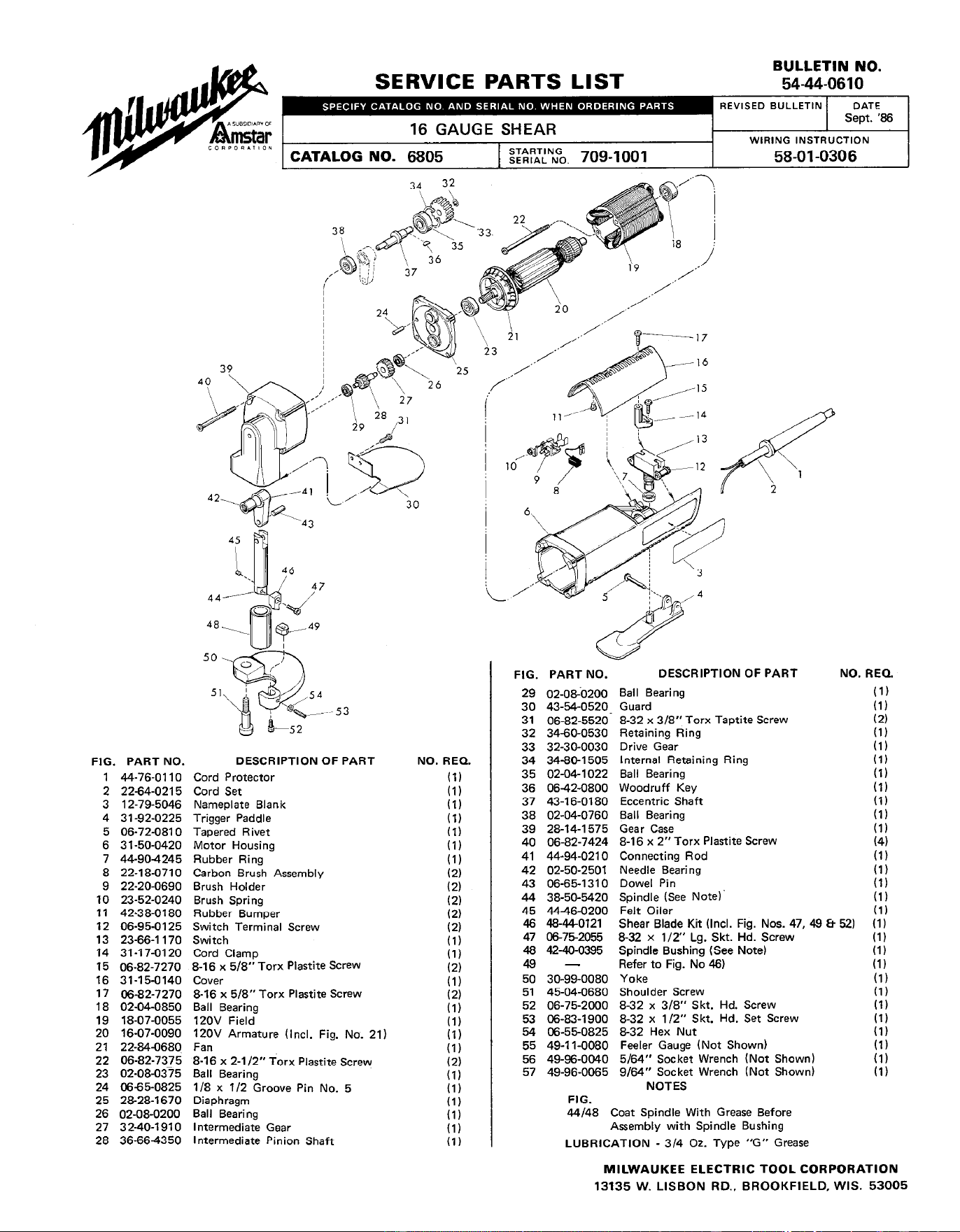
BULLETIN NO.
SERVICE PARTS LIST
54-44-0610
\
29
53
FIG. PART NO.
DESCRIPTION OF PART
1 44-76-0110
Cord Protector
2 22-64-0215
Cord Set
3 12-79-5046
Nameplate Blank
4 31-92-0225
Trigger Paddle
5 06-72-0810
Tapered Rivet
6 3 l-50-0420
Motor Housing
7 44904245
Rubber Ring
8 22-18-0710
Carbon Brush Assembly
9 22-20-0690
Brush Holder
10 23-52-0240
Brush Spring
11 42-38-0180
Rubber Bumper
12 06-95-0125
Switch Terminal Screw
13 23-66-l 170
Switch
14 31-17-0120
Cord Clamp
15 06-82-7270
B-16 x 5/B” Torx Plastite .%eW
16 31-15-0140
Cover
17 06-82-7270
B-16 x 5/B” Torx Plastite Screw
18 02-04-0850
Ball Bearing
19 18-07-0055
120V Field
20 16-07-0090
12OV Armature (Incl. Fig. No. 21)
2 1 22B4-0680
Fan
22 06-82-7375
B-16 x 2-l/2” Torx Plastite Screw
23 02-08-0375
Ball Bearing
24 0665-0825
l/B x l/2 Groove Pin No. 5
25 2&28-l 670
Diaphragm
26 02-08-0200 Ball Bearing
27 32-40-1910
Intermediate Gear
28 36-664350
Intermediate Pinion Shaft
NO. REQ.
(1)
(1)
(I)
(1)
(I)
(I)
(1)
(2)
(2)
(2)
(2)
(2)
(1)
(I)
(2)
(1)
(2)
(I)
(1)
(I)
(1)
(2)
(I)
(1)
(1)
(1)
(1)
(I)
FIG. PART NO.
29 02-oaO200
30 43-54-0520
31 06-82-5520
32 34-60-0530
33 32-30-0030
34 34-80-l 505
35 02-04-l 022
36 0642-0800
37 43-l 6-0180
38 02-04-0760
39 28-14-l 575
40 06-82-7424
41 44-94-0210
42 02-50-2501
43 06-65-l 310
44 38-50-5420
45 44-46-0200
46 48-440121
47 O&752055
48 42-40-0395
49 -
50 30-99-0080
51 45-04-0680
52 06-75-2000
53 06-83-l 900
54 06-550825
55 49-l l-0080
56 49-96-0040
57 49-96-0065
FIG.
DESCRIPTION OF PART
Ball Bearing
Guard
NO.
B-32 x 3/B” Torx Taptite Screw
Retaining Ring
Drive Gear
Internal Retaining Ring
Ball Bearing
Woodruff Key
Eccentric Shaft
Ball Bearing
Gear Case
B-l 6 x 2” Torx Plastite Screw
Connecting Rod
Needle Bearing
Dowel Pin
Spindle (See Note)’
Felt Oiler
Shear Blade Kit (Incl. Fig. Nos. 47, 49 Et 52)
B-32 x l/2” Lg. Skt. Hd. Screw
Spindle Bushing (See Note)
Refer to Fig. No 46)
Yoke
Shoulder Screw
B-32 x 3/B” Skt. Hd. Screw
B-32 x 112” Skt. Hd. Set Screw
&32 Hex Nut
Feeler Gauge (Not Shown)
5/64” Socket Wrench (Not Shown)
g/64” Socket Wrench (Not Shown)
NOTES
44/48 Coat Spindle With Grease Before
Assembly with Spindle Bushing
LUBRICATION - 314 Oz. Type “G” Grease
REQ.
(1)
(1)
(2)
(1)
(1)
(1)
(1)
(I)
(I)
(1)
(1)
(4)
(1)
(1)
(1)
(1)
(1)
(I)
(1)
(I)
(1)
(I)
(I)
(1)
(1)
(1)
(1)
(1)
(I)
MILWAUKEE ELECTRIC TOOL CORPORATION
13135 W. LISBON RD., BROOKFIELD, WIS. 53005