
USER MANUAL
V1.0
EcoFlow PowerStream
Microinverter

Disclaimer
Read this user manual carefully before using the product to ensure that you completely
understand the product and can correctly use it. After reading this user manual, keep
it properly for future reference. Improper use of this product may cause serious injury
to yourself or others, or cause product damage and property loss. Once you use this
product, it is deemed that you understand, approve and accept all the terms and
content in this document. EcoFlow is not liable for any loss caused by the user's failure
to use this product in compliance with this user manual.
In compliance with laws and regulations, EcoFlow reserves the right to final
interpretation of this document and all documents related to this product. This
document is subject to changes (updates, revisions, or termination) without prior notice.
Please visit EcoFlow's official website to obtain the latest product information.
Hereby, EcoFlow Inc. declares that EcoFlow PowerStream
Microinverter is in compliance with Directive 2014/53/EU. The
full text of the EU declaration of conformity is available at the
following internet addresses:
http://www.ecoow.com/eu/eu-compliance
http://www.ecoow.com/de/eu-compliance
http://www.ecoow.com/fr/eu-compliance
Hereby, EcoFlow Inc. declares that EcoFlow PowerStream
Microinverter is in compliance with Radio Equipment
Regulations 2017. The full text of the UKCA declaration of
conformity is available at the following internet address:
http://www.ecoow.com/uk/eu-compliance
The Bluetooth
®
word mark and logos are registered trademarks
owned by Bluetooth SIG, Inc. and any use of such marks by
EcoFlow Inc. is under license. Other trademarks and trade
names are those of their respective owners.
The crossed-out wheeled bin indicates that the electrical and
electronic (EE) product should not be discarded as unsorted
waste but must be sent to separate collection facilities for
recovery and recycling.

Contents
Safety Instruction
1
General safety 1
Environment requirements 1
Explanation of Symbols
2
Symbols on the decumentation 2
Symbols on the device 2
What's in the Box
3
Overview
4
System overview 4
Product overview 5
LED indication 6
Assembly
7
Pre-assembly 7
Assembly procedure 8
Connecting several solar panels in series or in parallel 13
Mounting the microinverter 17
Grounding considerations 19
EcoFlow App
20
Page of your PowerStream balcony solar system 20
Page of your microinverter 22
Unplug the Cables
23
Troubleshooting
24
Specifications
28

General safety
Safety Instruction
1. Please carefully read the documents before installing, operating or maintaining the
equipment. The documents are subject to change due to product updates or other reasons.
2. Do not put heavy objects on the equipment.
3. Ensure that all cables and connectors are intact and dry before connecting to prevent electric
shocks.
4. Use insulation tools or wear personal protective equipment when you install or operate the
equipment.
5. Do not install or operate the equipment in extreme weather events such as lightning, snow,
heavy rain, strong wind and so on.
6. Do not damage, smear or rip off any warning labels on the equipment.
7. Do not hit, pull, drag, squeeze or step on the equipment, or throw it into the re, as there is
risk of explosion.
8. After installing, please clean the remains of the installation, such as boxes, clipped cable ties,
ripped insulation materials, etc.
9. Do not modify or repair the equipment, please contact our customer service or qualied
personnel if necessary.
10.Use tools and the equipment correctly to prevent personal injuries and product damage.
11.Understand the components and function of the grid-tied PV power system. Make sure that
all electrical connections, and voltage and frequency at the connection point meet the local
microinverter grid-tie requirements.
12. Make sure the screws are tightened to the specied torque during installation (M5*12: 30
Kgf*cm; ST5*12: 45 Kgf*cm; M6*20: 90 Kgf*cm).
13.If you only connect solar panels and the battery with the microinverter without plugging into the
AC outlet, the microinverter shall be grounded.
14.It is strongly recommended to install an overcurrent circuit breaker between the equipment
and the grid.
15.The equipment may get more than 70 °C (158 °F) while in use. Do not touch its enclosure
before it cools down. Also, always keep the equipment out of reach of children and pets.
16.The installation location should be convenient for you to pull out the connectors.
17.Before you pull out the AC (or battery) connector from the microinverter, disconnect the cable
from the AC socket (or battery's) end.
18.Make sure the portable power station is off during the whole connection process.
19.You can only connect solar panels to the PV port and only connect an EcoFlow portable
power station to the battery port.
Environment requirements
1. Make sure the equipment is installed, operated or stored in a well ventilated place.
2. Do not install or operate the equipment near ammable, explosive, corrosive, caustic or moist
sources.
3. Do not expose the equipment to strong electromagnetic elds to avoid radio interference.
1
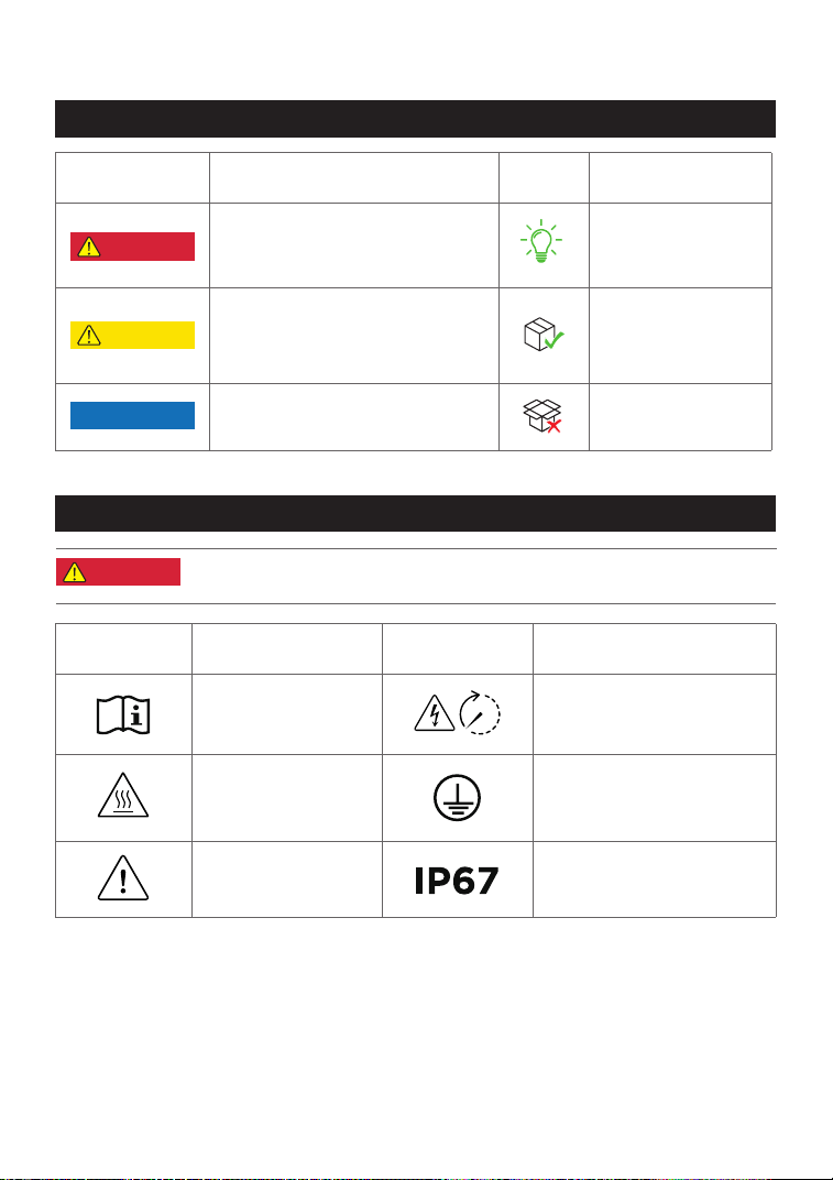
Explanation of Symbols
Symbol Explanation Symbol Explanation
Refer to the operation
instructions
Caution, risk of electric
shock; energy storage timed
discharge
Caution, hot surface
The position for connecting
the protection ground cable
Caution, risk of
danger
Ingress Protection rating
Symbols on the documentation
Symbols on the device
Symbol Explanation Symbol Explanation
A hazard with a high level of risk
which, if not avoided, will result in
death or serious injury.
A hazard with a low level of risk
which, if not avoided, will result
in minor injury, or demage to the
device.
Important information that you need
to pay attention to.
In a basic set
Indicates additional
information on correct
use or useful tips.
Optional (not in the
box)
DANGER
NOTICE
CAUTION
•
Do not damage, smear or cover any warning labels on the device. All
labels must be visible after installation.
DANGER
2
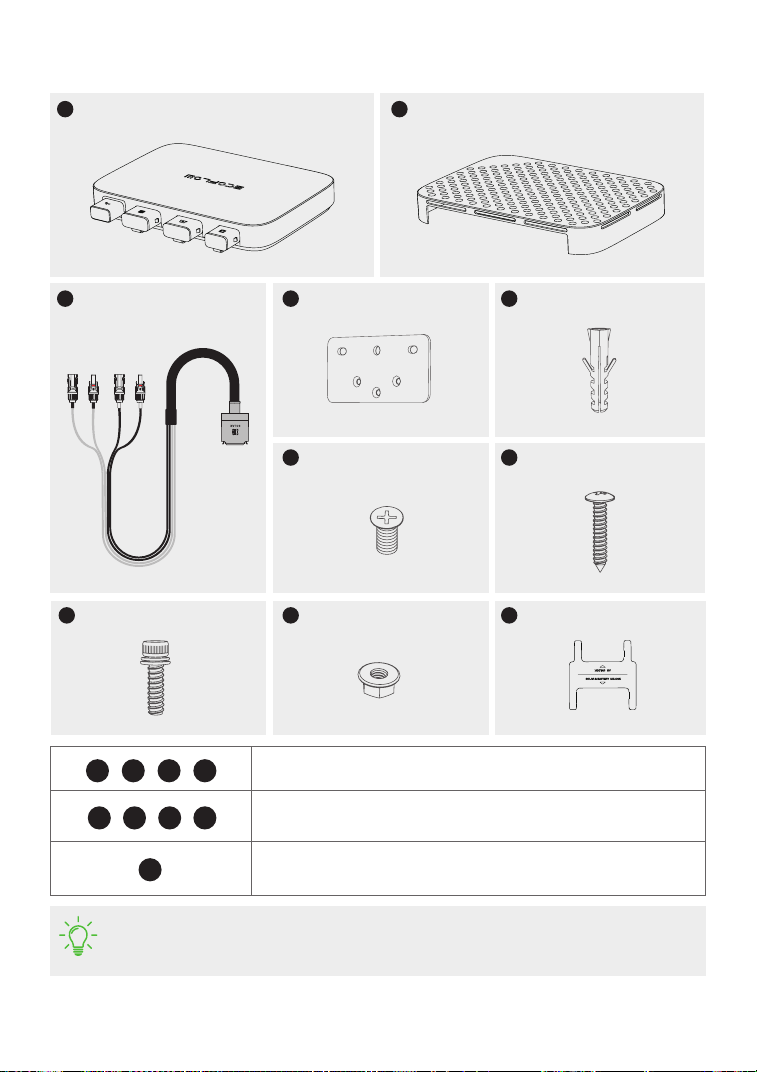
What's in the Box
M6*20
M5*12
Protective case
Installation board
BKW-Solar cable
• The images of the product and components may differ from the actual product.
• If there are missing or defective components, please contact EcoFlow customer
service.
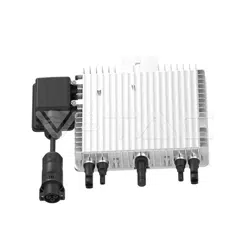
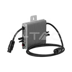
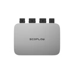
PowerStream Microinverter
A B
C
D
M5*40
F
E
ST5.5*25
G
H
M6 nut
I
Cable puller
J
X2 X1
X1
X1 X1
X2
X2X3
X1
X2
Used for mounting the microinverter on the wall. See "Mount on the
wall" for details.
Used for mounting the microinverter on the bracket. See "Mount on
the bracket" for details.
Used for disconnection, located at the bottom of the protective case.
See "Unplug the Cables" for details.
D
D E
G
H I
J
F
F
3
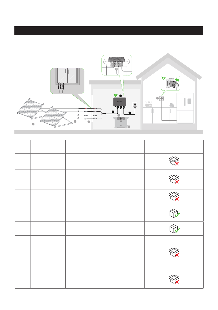
Overview
No. Name Description
In a basic set / Optional
(not in the box)
1 Solar panel
Up to two groups of solar panels can
be connected to one microinverter.
2
Extension
cable
Used for extending the connection
between the microinverter and the
solar panel.
3
EcoFlow Super
Flat Cable
Used for passing through a window
or a door.
4
EcoFlow BKW-
Solar Cable
Used for the connection between the
microinverter and the solar panel.
5
PowerStream
Microinverter
/
6
Battery
connection
cable
Used for the connection between
the microinverter and the EcoFlow
portable power station.
Three types: BKW-DELTA EB cable,
BKW-DELTA PRO cable, BKW-RIVER
cable.
7
EcoFlow
portable power
station
Used for power storage.
System overview
1
2
3
6
7
9
4
5
8
2.4G
4
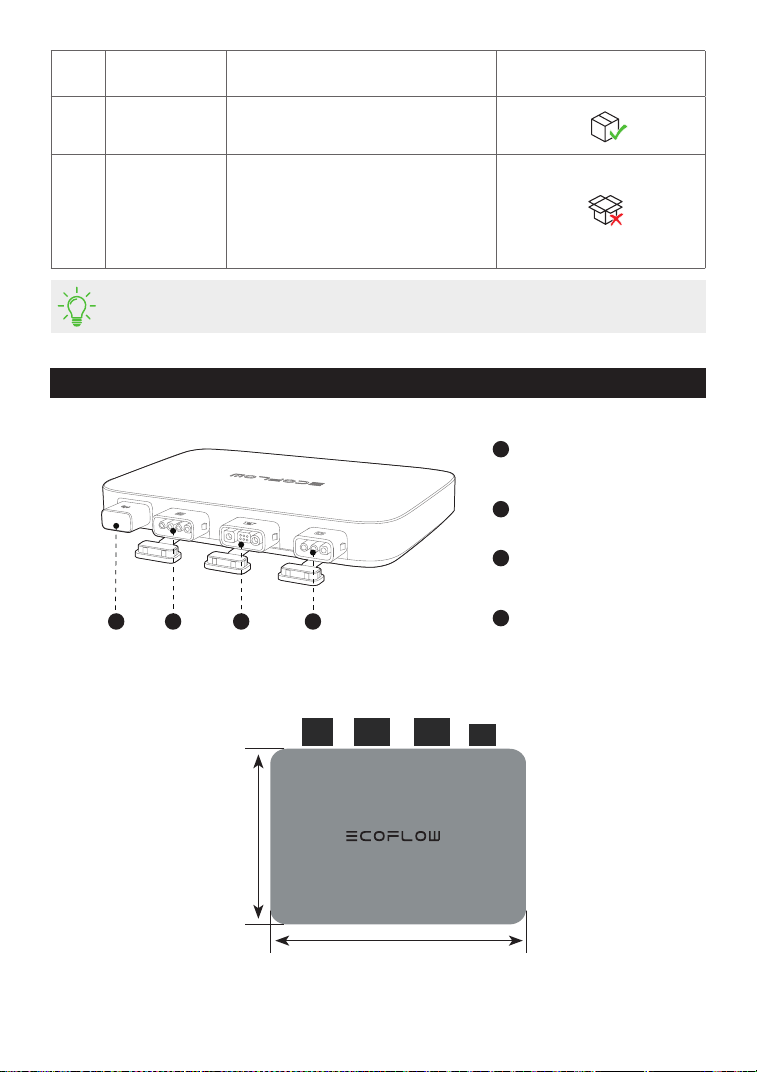
1
Antenna
Works with the EcoFlow app and
Smart Plugs
2
PV port
Connects with solar panels
3
Battery port / DC port
Connects with an EcoFlow portable
power station
4
AC output port
Connects to the power grid
Product overview
1 2 3 4
•
You can purchase optional accessories from the official EcoFlow website.
No. Name Description
In a basic set / Optional
(not in the box)
8
EcoFlow BKW-
AC cable
Used for connection of the
microinverter to the power grid.
9
EcoFlow Smart
Plug
Used for monitoring the power
of appliances and for wireless
communication with the
microinverter to optimize the energy
usage.
242 mm
169 mm
5
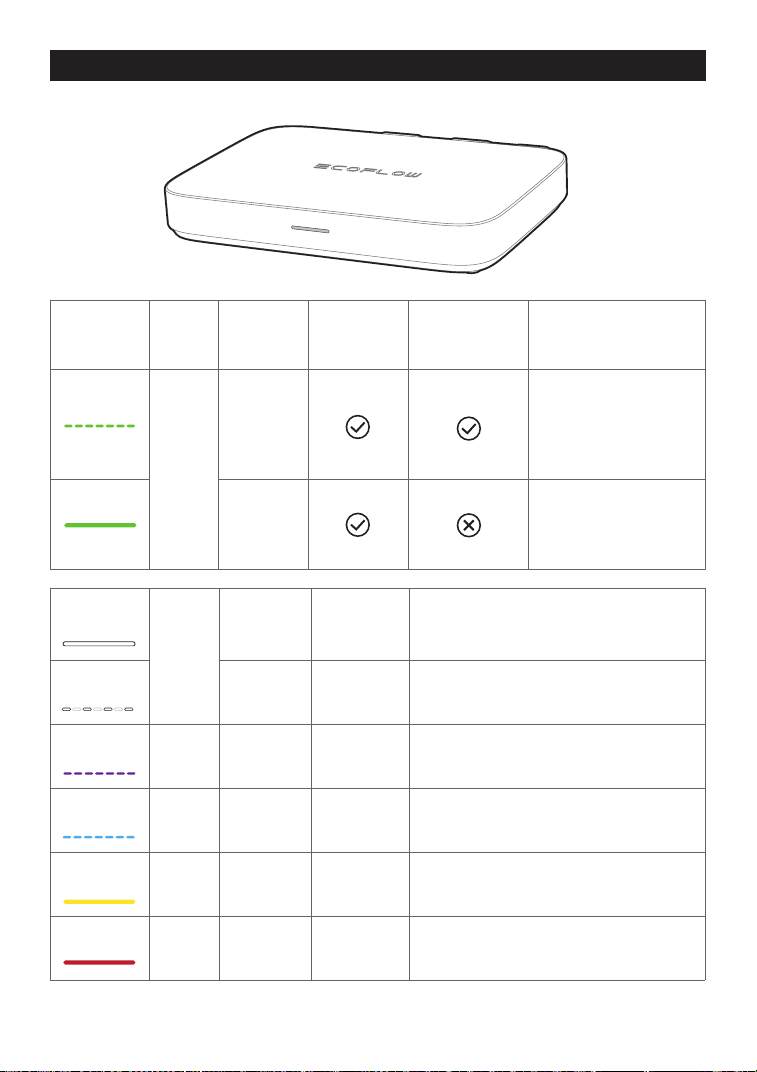
LED
indicator
Color Status
Feeding
electricity
(power grid)
Feeding
electricity
(Smart Plug)
Detailed explanation
Green
Breathing
There is power input
and AC output.
Electricity is fed to
Smart Plug(s) for use by
appliances.
Solid
There is power input
and AC output, but no
electricity is fed to
Smart Plug(s).
White
Solid Power on
There is PV input or/and the power station
discharges (DC input), without any power
output.
Breathing Charging
There is PV input and the power station is
charged (DC output), without AC out.
Purple Blinking Updating
Updating the rmware.
Blue Blinking Pairing Pairing with EcoFlow app.
Yellow Solid Warning See "Troubleshooting" for details.
Red Solid Error See "Troubleshooting" for details.
LED indication
6
Assembly
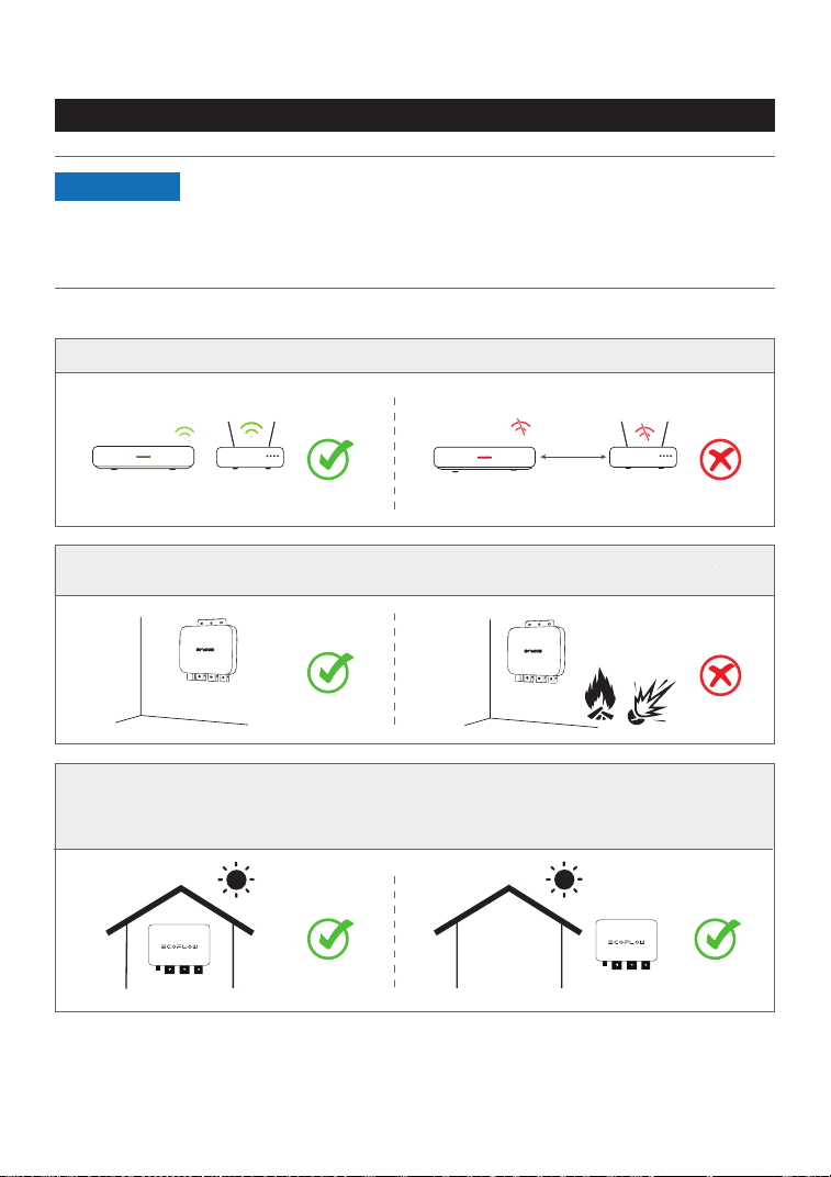
Pre-assembly
Select a location for the PowerStream Microinverter
2.4G
2.4G
.
Do not place or install the microinverter in an area where flammable or explosive materials
are stored.
Make sure that the microinverter is within the Wi-Fi coverage.
The IP rating of the microinverter is IP 67, hence, it can be installed either indoors or outdoors.
However, the EcoFlow portable power station is not waterproof. If your system includes a
portable power station, keep both of them indoors.
.
•
This user manual only provides the cable connection method and the
mounting method for the microinverter. For installing the solar panel,
please refer to the instructions for the solar panel and its accessories.
•
If you wish to verify the solar system, complete the assembly on a
sunny day.
NOTICE
7
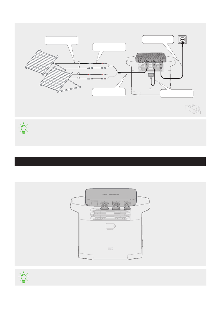
Measure the distance
1. Place the microinverter on the Ecoow portable power station.
•
If you need to mount the microinverter, please refer to "Mounting the
Microinverter".
Assembly procedure
•
The lengths of cables vary in different countries or regions. Please refer to the
actual products.
•
Except for the standard BKW-Solar cable and the BKW-AC cable, other cables
need to be purchased from the official website.
Extension cable 3m
Super flat cable 0.5m
BKW-Solar cable 2m
BKW-AC cable
1.5m/3m/5m
Battery connection
cable 0.4m/0.5m/1m
USB port
Logic
interface
8
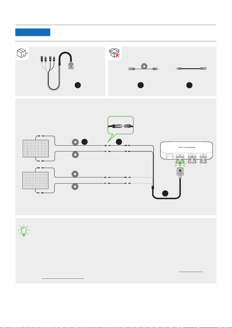
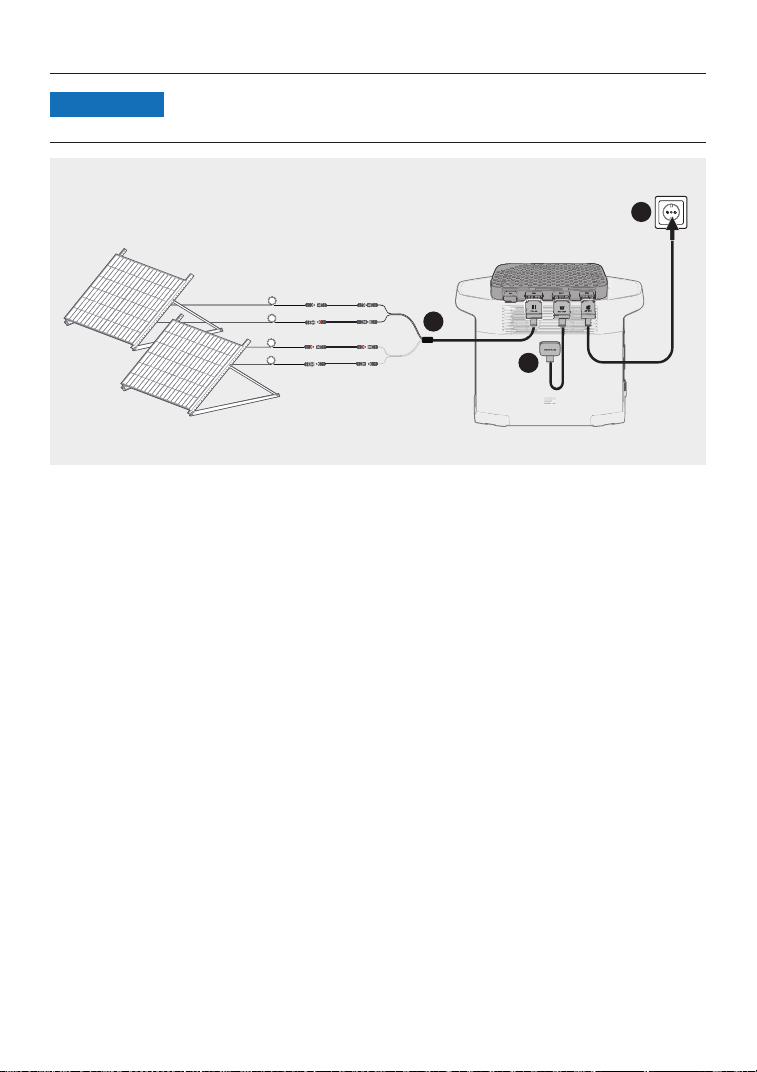
2. Connect with solar panels.
• After the solar panels capture solar radiation, they provide direct current to the
microinverter. At this time, the LED indicator will light up white.
• If you connect several solar panels in series or in parallel as a group, refer to
"Connecting several solar panels in series or in parallel".
• If you connect the EcoFlow River-series portable power station to the DC port
of the microinverter, it is recommended to connect solar panels to the power
station, otherwise, the energy will not be stored.
For the connection, refer to the user manual of the power station. Download
usermanualshere.
400W400W
400W400W
Group 1
Group 2
Solar
panel 2
• A BKW-Solar cable includes two groups of MC4 connectors, which can
connect with two groups of solar panels.
NOTICE
Solar
panel 1
9
BKW-Solar cable Extension cable Super flat cable
a
X1
a
b
X4
b
c
X4
c
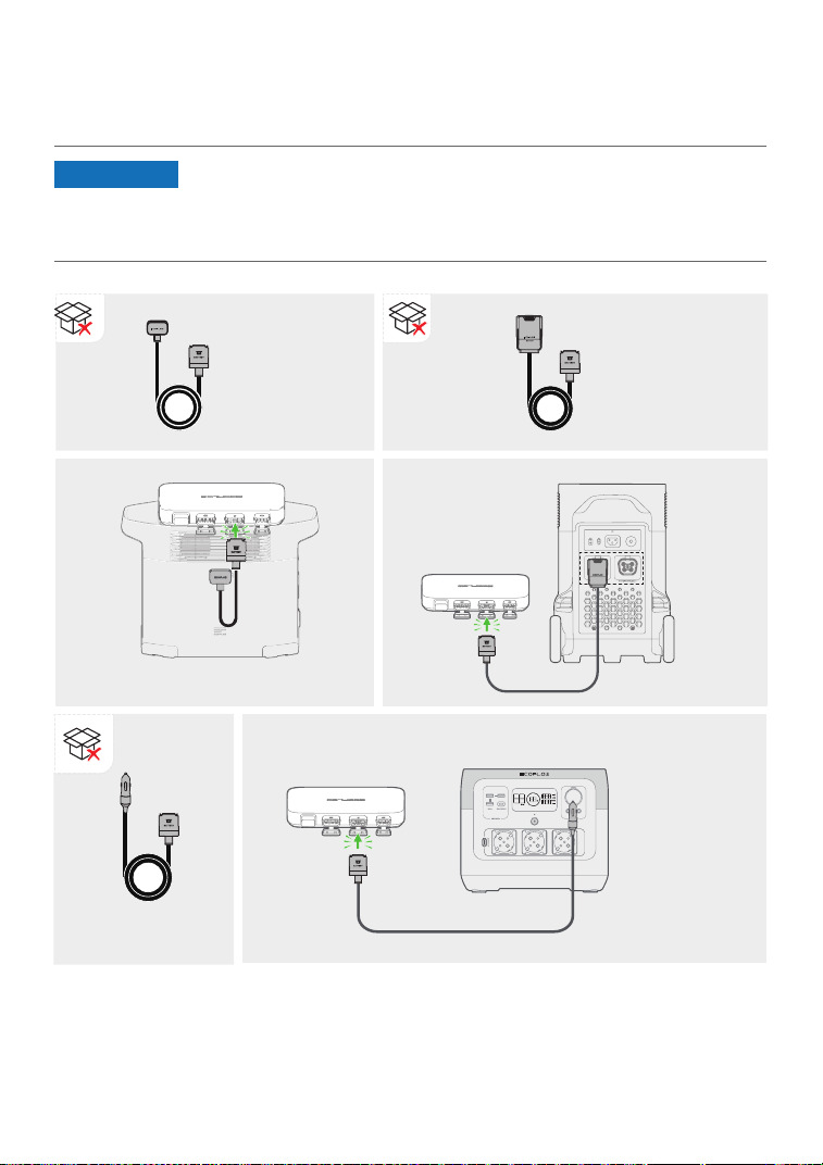
3. Connect with the EcoFlow portable power station.
There are three types of battery connection cables for different EcoFlow portable power stations,
as shown in the gures below.
BKW-DELTA
EB cable
Delta 2 series and Delta Max series
BKW-DELTA
PRO cable
Delta Pro series
River series, Delta
mini, and Delta 1300
BKW-RIVER
cable
• Make sure the portable power station is off during the whole connection
process.
• If you use the EcoFlow BKW-RIVER cable for the EcoFlow River-series
portable power station, the power station only discharges power but does
not receive a charge.
NOTICE
10
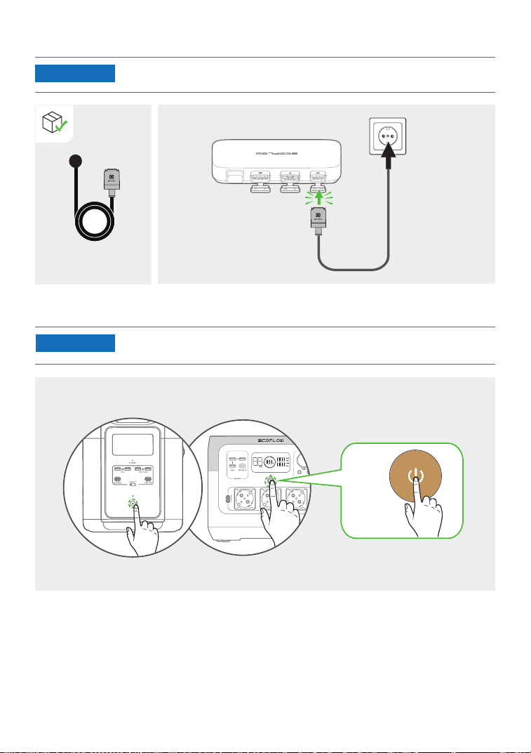
5. Turn on the EcoFlow portable power station.
4. Connect to the power grid.
• If your PowerStream balcony solar system does not include a portable power
station, skip this step.
• Please conrm that the AC socket is switched on, and the power grid is
being powered.
NOTICE
NOTICE
BKW-AC cable
X1
ON
11
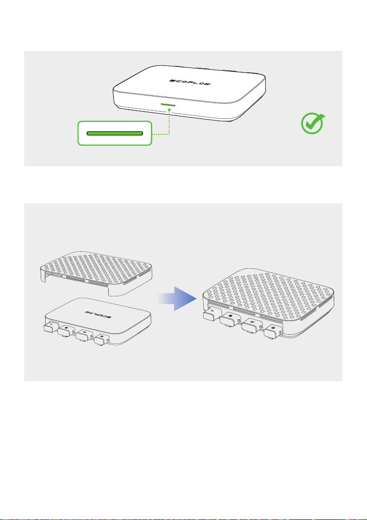
After completing the connection, the LED indicator will light up green when the solar panel
captures solar radiation and the microinverter outputs AC.
It is highly recommended to install the protective case on the top of the microinverter to protect
you from high temperature burns. The protective case is in the box.
12
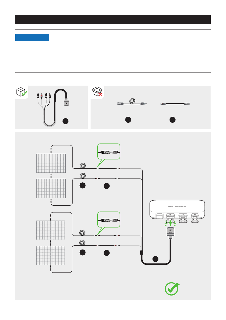
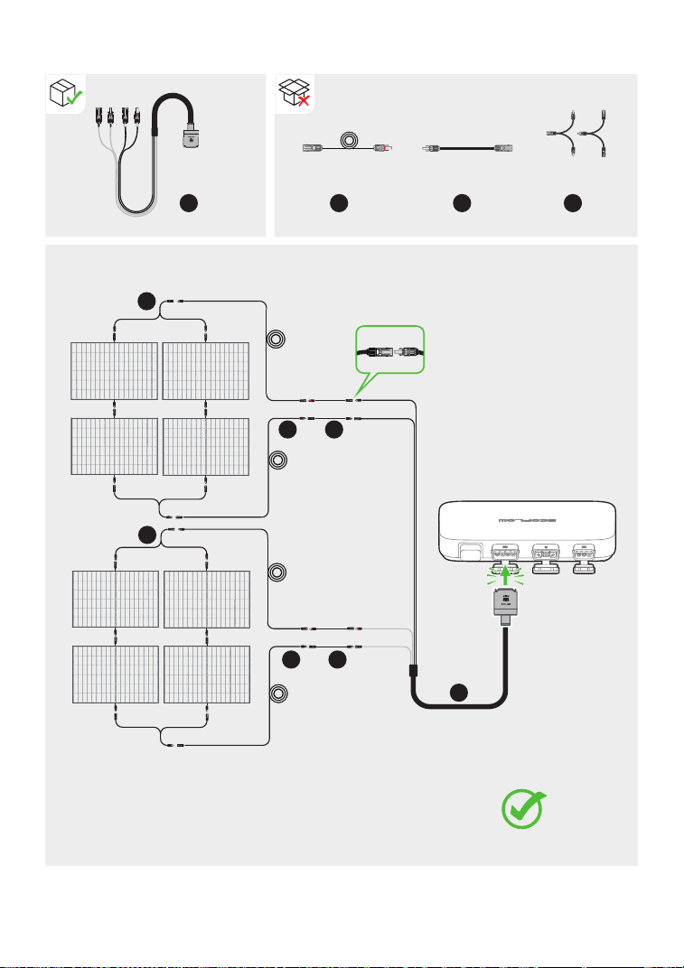
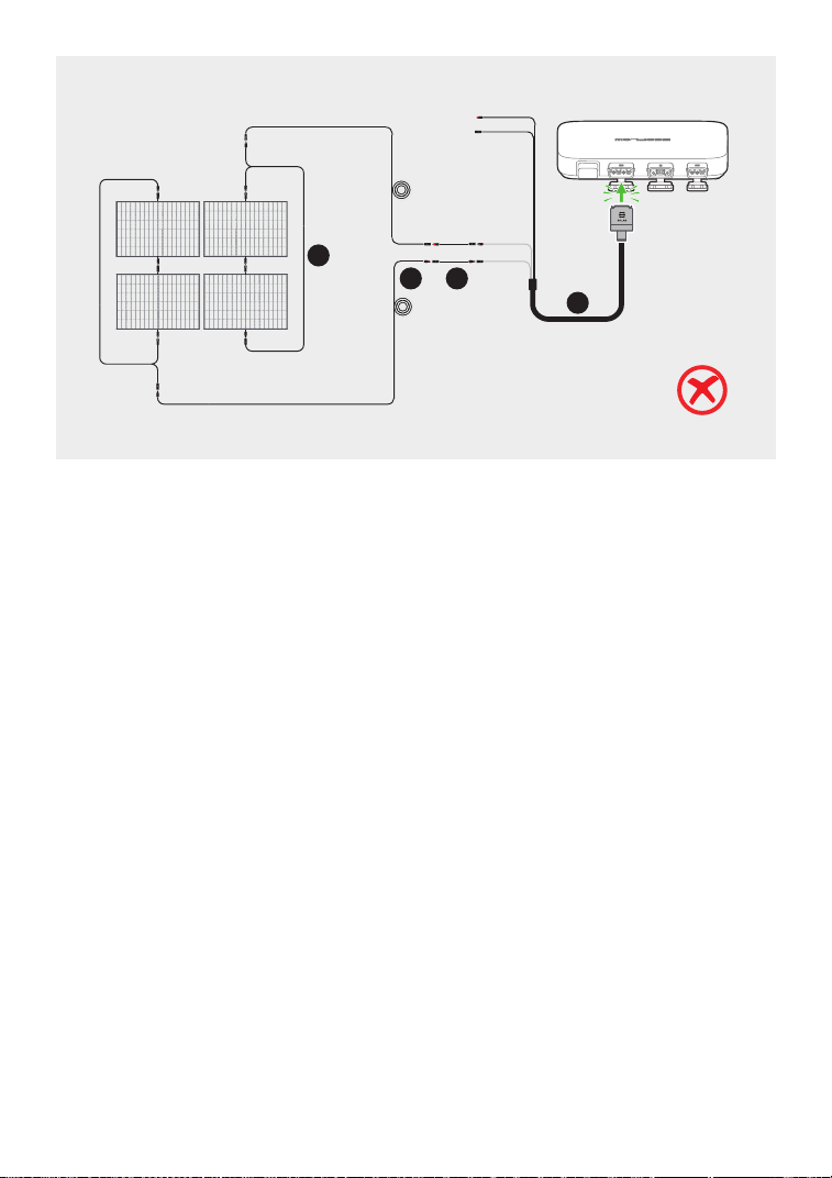
Solar panels in series
Connecting several solar panels in series or in parallel
• If you connect several solar panels in series or in parallel as a group, make
sure that the maximum operating voltage (Vm) and maximum operating
current (Im) of each group do not exceed the maximum input voltage
(55V) and maximum output current (13A) of the microinverter PV input.
• The maximum operating voltage (Vm) and maximum operating current
(Im) of solar panels must to be consistent respectively.
BKW-Solar
cable
Extension cable Super flat cable
a
X1
b
X4
c
X4
NOTICE
a
b
b
c
c
Solar
panel 1
Solar
panel 3
Solar
panel 2
Solar
panel 4
100W100W
100W100W
100W100W
100W100W
Vm (solar panel 1) + Vm (solar panel 2) < 55V
Vm (solar panel 3) + Vm (solar panel 4) < 55V
13
Solar
panel 1
Solar
panel 2
Solar
panel 3
100W100W
100W100W
100W100W
a
b c
14
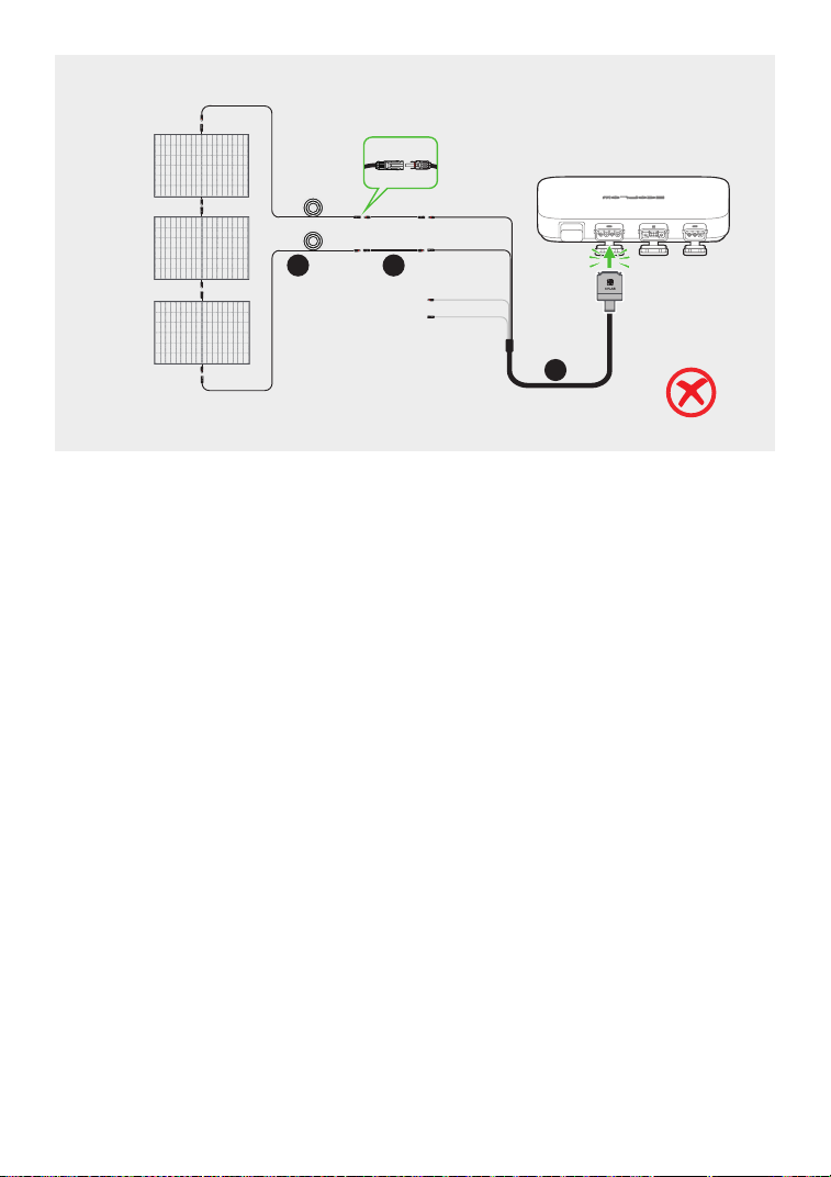
Solar panels in both series and parallel
Vm (solar panel 1) + Vm (solar panel 3) < 55V
Im (solar panel 1) + Im (solar panel 2) < 13A
BKW-Solar
cable
Extension cable Super flat cable Solar parallel
connection cable
a
X1
a
b
X4
b
b
c
X4
c
c
d
X2
d
d
Solar
panel 1
Solar
panel 5
Solar
panel 3
Solar
panel 7
Solar
panel 2
Solar
panel 6
Solar
panel 4
Solar
panel 8
100W100W
100W100W
100W100W
100W100W
100W100W
100W100W
100W100W
100W100W
15
a
b c
d
Solar
panel 1
Solar
panel 3
Solar
panel 2
Solar
panel 4
100W100W
100W100W
100W100W
100W100W
16
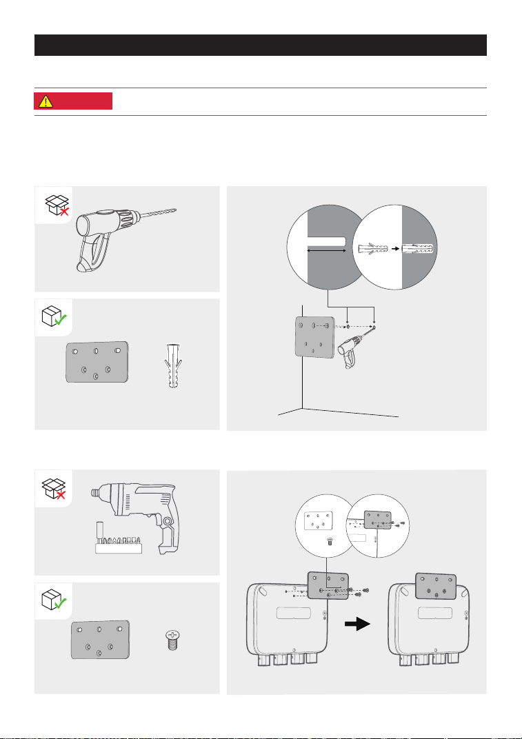
2. Install M5*12 in the corresponding positions on back of the microinverter.
×1
×3
1. Use the installation board to locate the hole and drill two holes about 41 mm deep in the wall.
Then, insert M5*40 into the holes.
Mount on the wall
If your balcony solar system does not include a power station, you can mount the microinverter.
Mounting the microinverter
Diller Ф8mm (0.31in.)
(not provided)
Installation board
Installation board
M5*40
M5*12
X2X1
X3X1
41mm
• Wear protective goggles or gloves when drilling holes.
DANGER
Cordless electric screwdriver
x 2
17
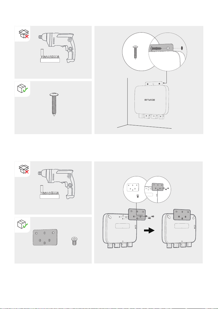
3. Insert ST5.5*25 into M5*40 through holes of the board.
×2
ST5.5*25
Cordless electric screwdriver
Mount on the bracket
1. Install M3*6 in the corresponding positions on back of the microinverter.
Installation board M5*12
×1
×3
X2
X2X1
Cordless electric screwdriver
18
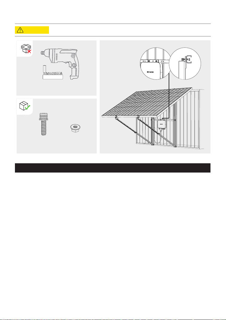
• Please install vertically ≤ 15° for stability and safety.
2. Install two M6*20 in two holes of the installation board, and tighten M6 nuts on them.
There is an earth wire inside the supplied BKW-AC cable, so grounding can be done directly by
using this BKW-AC cable.
If you need to add an additional grounding conductor:
Tools and components (not provided): an M4*6 screw, a grounding wire (cross-section ≥ 4 mm²)
with a connection tool, safety gloves and a driller.
1. Find the grounding terminal on the bottom of the microinverter.
2. Insert M4*6 into the grounding terminal through the connection tool of the grounding cable.
Grounding considerations
Cordless electric screwdriver
M6*20 M6 nut
X2 X2
CAUTION
19
0
0
W
0
W
0
W
0
W
0
wh
58%
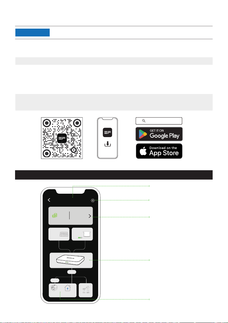
Control, monitor, and customize your EcoFLow PowerStream microinverter from afar with the
EcoFlow app.
Download at: https://download.ecoow.com/app
Privacy policy
By using EcoFlow Products, Applications, and Services, you consent to the EcoFlow Term of
Use and Privacy Policy, which you can access via the “About” section of the “User” page on the
EcoFlow App or on the ofcial EcoFlow website at
https://www.ecoow.com/policy/terms-of-use and
https://www.ecoow.com/policy/privacy-policy
EcoFlow App
Page of your PowerStream balcony solar system
Name of your
PowerStream system
Check cumulative power
generation and savings.
Tap ">" to view historical
data by data, week,
month, or year.
Check real-time power
generation, storage and
supply.
Tap to enter the Setting
page of your system.
Number of Smart Plugs
in the system
• The gures are for reference only, please refer to the actual app interface.
NOTICE
EcoFlow App
20
PowerStream system
Solar panel
Amount
Smart plugs Other Ioads
Power grid
Total revenue
€
Battery
Total generation
Home
1
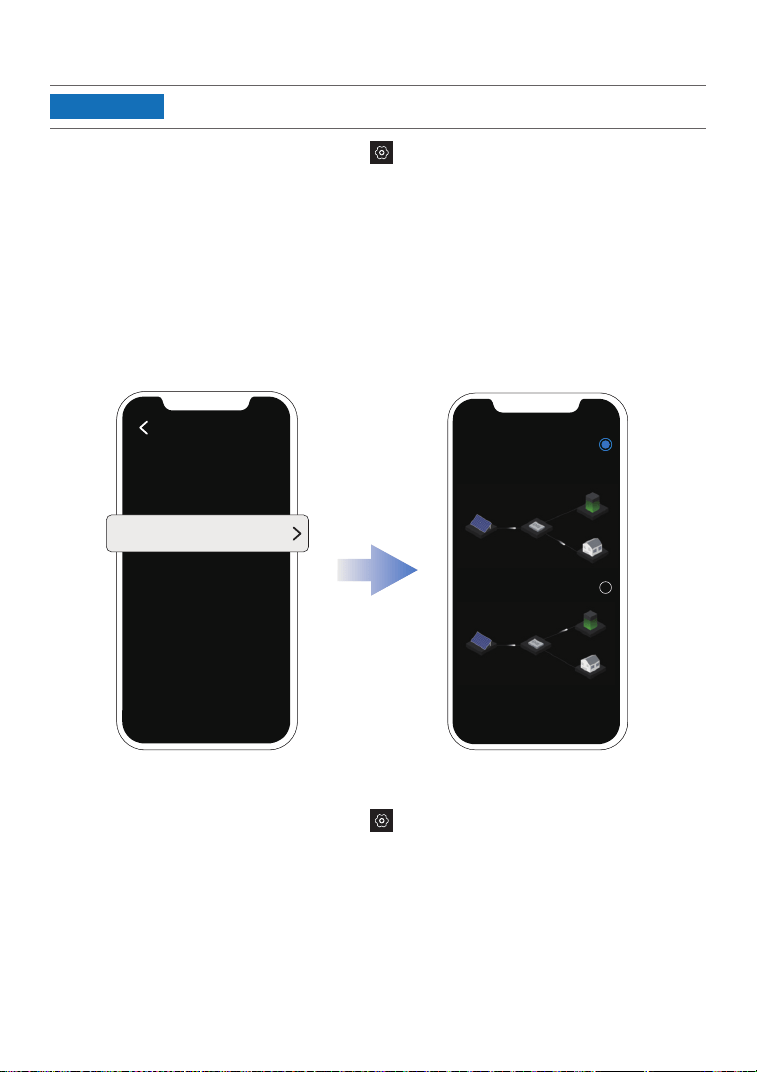
Setting the power supply mode
On the page of your PowerStream system, tap > "Power supply mode". Then, select the
mode you need.
•
Prioritize power supply: Select this option if you want to prioritize meeting the power
consumption of electrical appliances. In this mode, when the power supply exceeds the
demand for electrical appliances, the portable power station will be charged. When the
demand for electrical appliances is less than the power supply, the portable power station
will discharge.
•
Prioritize power storage: Select this option if you want to prioritize charging the portable
power station until it reaches its charging limit. In this mode, the portable power station will
not discharge to the microinverter.
Power supply mode
System setting
Prioritize power
supply
Prioritize power
storage
• This feature can be enabled when the portable power station is connected.
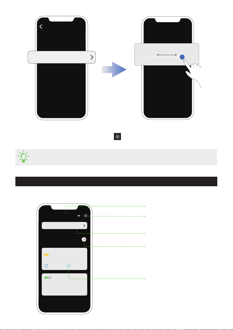
Setting the AC output power demand
On the page of your PowerStream system, tap > "AC output power demand".
The AC output power demand = Power demand from other loads + Load power of smart plugs
NOTICE
21
EcoFlow WN100
0
kwh
0
w
0.3
kw
0.3 kw
55%
0.2
kw 0.4 kw
Name of your microinverter
Check cumulative power
generation and savings.
Tap ">" to view historical
data by data, week, month,
or year
Check real-time power
generation, storage and
supply
Tap to enter the "Setting"
page of your microinverter
Tap to enter the affiliated
system
Page of your microinverter
AC output power demand
In the list of your devices, tap the microinverter to go to the page of your microinverter.
Firmware update
On the page of your PowerStream system, tap
> "Firmware" to check the firmware version
of the microinverter and the smart plug to update the firmware.
• To update the microinverter separately, you can also update the rmware on the
"Setting" page of your microinverter.
System setting
Power demand from other loads
800 W
/ 600W
0 W
Total generation
0
€
22
Total revenue
Affiliated system: PowerStream system
Current generation
Charging
Discharging
Other loads
Smart plugs
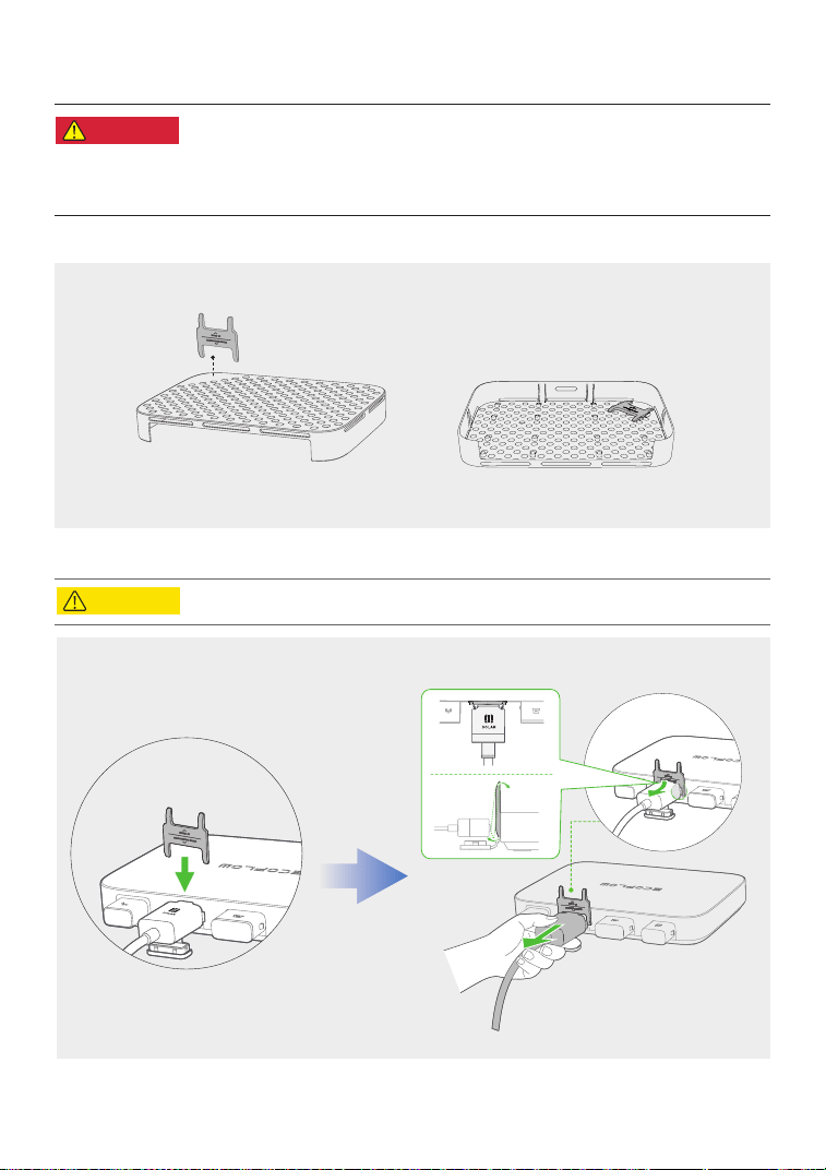
Unplug the Cables
•
Do not remove the connector with your hand only. Please use the
cable puller supplied with the product to assist in pulling out the
connector.
•
If you have installed the protective case, please remove the protective
case from the microinverter before you pull out the connector.
Where is the cable puller?
Protective case
Cable puller
How to use the cable puller?
• Before you remove the battery connection cable, turn off the power station.
DANGER
CAUTION
23
Remove connectors in the following order
:
• Before you pull out the AC (or battery) connector from the microinverter,
disconnect the cable from the AC socket (or battery's) end.
NOTICE
1
2
3
24

Error
code
LED
indicator
Name Suggestion
1 Red Device error
1. Unplug all cables connected to the PowerStream.
2. Wait for 30 seconds, and then plug in all the cables.
3. If the issue persists, contact customer service.
2 Red Device error
1. Unplug all cables connected to the PowerStream.
2. Wait for 30 seconds, and then plug in all the cables.
3. If the issue persists, contact customer service.
4 Red Device error
1. Unplug all cables connected to the PowerStream.
2. Wait for 30 seconds, and then plug in all the cables.
3. If the issue persists, contact customer service.
8
(Displayed
in app)
Grid error
1. Try pulling out the AC cable and inserting it back
again. Make sure that the plug is securely inserted.
2. If the issue persists, the power grid is probably faulty.
Wait for the power grid to recover.
3. If the issue persists for more than 1 hour, contact
customer service.
16
(Displayed
in app)
Grid error
1. Try pulling out the AC cable and inserting it back
again. Make sure that the plug is securely inserted.
2. If the issue persists, the power grid is probably faulty.
Wait for the power grid to recover.
3. If the issue persists for more than 1 hour, contact
customer service.
32
(Displayed
in app)
Grid error
1. Try pulling out the AC cable and inserting it back
again. Make sure that the plug is securely inserted.
2. If the issue persists, the power grid is probably faulty.
Wait for the power grid to recover.
3. If the issue persists for more than 1 hour, contact
customer service.
Troubleshooting
• Do not attempt to repair the microinverter.
If the LED indicator turns yellow or red, warning or errors occur. Please follow the instructions
in the app or the table below to deal with the problem. If it is not eliminated, please contact the
customer service.
DANGER
25

64
(Displayed
in app)
Grid error
1. Try pulling out the AC cable and inserting it back
again. Make sure that the plug is securely inserted.
2. If the issue persists, the power grid is probably faulty.
Wait for the power grid to recover.
3. If the issue persists for more than 1 hour, contact
customer service.
128
(Displayed
in app)
Grid error
1. Try pulling out the AC cable and inserting it back
again. Make sure that the plug is securely inserted.
2. If the issue persists, the power grid is probably faulty.
Wait for the power grid to recover.
3. If the issue persists for more than 1 hour, contact
customer service.
256 Red Device error
1. Unplug all cables connected to the PowerStream.
2. Wait for 30 seconds, and then plug in all the cables.
3. If the issue persists, contact customer service.
512 Red Device error
1. Unplug all cables connected to the PowerStream.
2. Wait for 30 seconds, and then plug in all the cables.
3. If the issue persists, contact customer service.
1024 Red Device error
1. Unplug all cables connected to the PowerStream.
2. Wait for 30 seconds, and then plug in all the cables.
3. If the issue persists, contact customer service.
4096
(Displayed
in app)
Disconnected
from grid
1. Try pulling out the AC cable and inserting it back
again. Make sure that the plug is securely inserted.
2. If the issue persists, the power grid is probably faulty.
Wait for the power grid to recover.
3. If the issue persists for more than 1 hour, contact
customer service.
16384 Red Device error
1. Unplug all cables connected to the PowerStream.
2. Wait for 30 seconds, and then plug in all the cables.
3. If the issue persists, contact customer service.
4 Yellow
Incorrect
wiring of the
solar panel
Make sure the solar panel is correctly wired. If the issue
persists, contact customer service.
8 Yellow
Incorrect
wiring of the
solar panel
Make sure the solar panel is correctly wired. If the issue
persists, contact customer service.
16 Yellow
Device
temperature
too high
Keep the ambient temperature within the range of
-40 °C to 50 °C. If the issue persists, contact customer
service.
26

32 Yellow
Temperature
too low
Keep the ambient temperature within the range of
-40 °C to 50 °C. If the issue persists, contact customer
service.
64 Red
Overvoltage
at the solar
panel
Check if the open-circuit voltage of the solar panel is
between 11V and 55V.
16 Yellow
Temperature
too high
Keep the ambient temperature within the range of
-40 °C to 50 °C. If the issue persists, contact customer
service.
4 Yellow
Battery level
of the power
station is too
high
Discharge electricity from the power station until the
battery level drops to 90%.
16 Yellow
Abnormal
voltage at the
DC port
Make sure the voltage at the DC port falls within the
range of 11V to 15V or 40V to 59V.
32 Yellow
Abnormal
voltage at the
DC port
Make sure the voltage at the DC port falls within the
range of 11V to 15V or 40V to 59V.
8 Yellow
Temperature
too high
Keep the ambient temperature within the range of
-40 °C to 50 °C. If the issue persists, contact customer
service.
16 Yellow
Temperature
too low
Keep the ambient temperature within the range of
-40 °C to 50 °C. If the issue persists, contact customer
service.
27

Specifications
General info
Model
EFWN511/EFWN511B
Dimension
242×169×33 (mm)
Weight
Approximately 3 kg
PV port
Operating voltage
11 - 55 Vd.c.
Maximum input voltage
55 Vd.c.
Maximum input current
13 A
Initial input voltage
15 Vd.c.
Anti-reverse connection protection
Supported
Overvoltage
Ⅱ
Max. PV short circuit current (Isc PV)
14 A
Max. inverter backfeed current to the array
0 A
BAT / DC port
Discharging mode
Maximum input current
13 A
Input voltage
11 -15 Vd.c. , 40 - 59 Vd.c.
Maximum input voltage
59 Vd.c.
Charging mode
Charging voltage
30 - 58 Vd.c.
Maximum charging current
13 A
Rated charging voltage
48 Vd.c.
Overvoltage
Ⅱ
Battery input short circuit current rating
20 A
AC port
28

Output voltage
220/230/240 Va.c.
Output frequency
50 Hz
Output power factor
±0.8 ~ 1
Maximum output current
EFWN511: 3.7 A
EFWN511B: 2.8 A
Maximum output fault current
18.4 A
Maximum output overcurrent protection
4 A
THDI
<=3%@100% load
Overvoltage
Ⅲ
Others
Placed Indoors or outdoors
Pollution degree PD3
Ingress Protection rating IP67
Operating temperature -40 °C to 50 °C (-40 °F to 122 °F)
Humidity 0 % to 100 %
Altitude ≤2000 m
Wet location Yes
Type of inverter Isolated
Protective class 1
Wi-Fi (2.4G)
Frequency range:
20M: 2412 - 2472 MHz / 40M: 2422- 2462 MHz
Maximum output power: ≤ 20 dBm
Bluetooth
®
Frequency range: 2402-2480MHz
Maximum output power: ≤ 20 dBm
For updated parameters, please go to our website to download the latest user manual.
29