
Your new tool has been engineered and manufactured to WEN’s highest standards for dependability, ease
of operation, and operator safety. When properly cared for, this product will supply you years of rugged,
trouble-free performance. Pay close attention to the rules for safe operation, warnings, and cautions. If
you use your tool properly and for its intended purpose, you will enjoy years of safe, reliable service.
IMPORTANT:
NEED HELP? CONTACT US!
Have product questions? Need technical support?
Please feel free to contact us at:
MODEL 65911
For replacement parts visit
800-232-1195 (M-F 8am-5pm CST)
WENPRODUCTS.COM
WENPRODUCTS.COM
10
-
INCH
DRUM SANDER

TABLE OF CONTENTS
Specifications ......................................................................................2
Introduction ........................................................................................3
General Safety Rules ...........................................................................4
Electrical Information ..........................................................................6
Specific Rules for Your Drum Sander ..................................................7
Know Your Drum Sander .....................................................................8
Unpacking ...........................................................................................9
Assembly ..........................................................................................10
Sandpaper Installation .......................................................................14
Preparation ........................................................................................16
Adjustments ......................................................................................21
Maintenance ......................................................................................25
Troubleshooting Guide ......................................................................28
Exploded View & Parts List ...............................................................30
Warranty Statement ...........................................................................34
SPECIFICATIONS
Model Number 65911
Motor 120V, 60Hz, 10.5A
Drum Speed 1700 RPM (60Hz)
Sandpaper Speed 2300 FPM
Conveyor Feed Speed 0 to 10 FPM
Maximum Workpiece Width 9-7/8" (250mm)
Minimum Workpiece Width 3/4" (19mm)
Maximum Workpiece Height 3-1/8" (80mm)
Minimum Workpiece Height 3/16" (5mm)
Minimum Workpiece Length 4-3/4" (120mm)
Sandpaper Width 3-1/4" (82mm)
Sandpaper Length 62-1/2" (1585mm)
Sanding Drum Size 5-1/8" x 10-1/4" (132mm x 260mm)
Dust Port Diameter 4" (101.6mm)
Floor-to-Conveyor Height 30-1/4"
Assembled Dimension 28-3/8" x 23-1/4" x 47-1/4"
Weight 161 lbs
NOTE: Your drum sander is compatible with the WEN 28200 10 ft. dust hose and the WEN 28221 20 ft.
dust hose, available at wenproducts.com.
Sandpaper may be purchased from wenproducts.com by searching 65910.
2

INTRODUCTION
Thanks for purchasing the WEN drum sander. We know you are excited to put your tool to work,
but first, please take a moment to read through the manual. Safe operation of this tool requires that
you read and understand this operator’s manual and all the labels affixed to the tool. This manual
provides information regarding potential safety concerns, as well as helpful assembly and operating
instructions for your tool.
NOTE: The following safety information is not meant to cover all possible conditions and situations
that may occur. WEN reserves the right to change this product and specifications at any time without
prior notice.
Keep this manual available to all users during the entire life of the tool and review it
frequently to maximize safety for both yourself and others.
WARNING:
Indicates danger, warning, or caution. The safety symbols and the explanations
with them deserve your careful attention and understanding. Always follow the safety
precautions to reduce the risk of fire, electric shock and personal injury. However, please
note that these instructions and warnings are not substitutes for proper accident prevention
measures.
3

GENERAL SAFETY RULES
Safety is a combination of common sense, staying alert, and knowing how your item works.
SAVE THESE SAFETY INSTRUCTIONS.
WORK AREA SAFETY
1. Keep work area clean and well lit. Cluttered or dark areas invite accidents.
2. Do not operate power tools in explosive atmospheres, such as in the presence of flammable
liquids, gases or dust. Power tools create sparks which may ignite the dust or fumes.
3. Do not expose power tools to rain or wet conditions. Water entering a power tool will increase the
risk of electric shock.
4. Keep children and bystanders away while operating a power tool.
ELECTRICAL SAFETY
1. Power tool plugs must match the outlet. Never modify the plug in any way. Do not use any adapter
plugs with earthed (grounded) power tools. Unmodified plugs and matching outlets will reduce risk
of electric shock.
2. Avoid body contact with earthed or grounded surfaces such as pipes, radiators, ranges and
refrigerators. There is an increased risk of electric shock if your body is earthed or grounded.
3. Do not abuse the cord. Never use the cord for carrying, pulling or unplugging the power tool. Keep
cord away from heat, oil, sharp edges or moving parts. Damaged or entangled cords increase the risk
of electric shock.
4. If operating a power tool in a damp location is unavoidable, use a ground fault circuit interrupter
(GFCI) protected supply. Use of a GFCI reduces the risk of electric shock.
PERSONAL SAFETY
1. Stay alert. Watch what you are doing and use common sense when operating a power tool. Do
not use a power tool while you are tired or under the influence of drugs, alcohol or medication. A
moment of inattention while operating power tools may result in serious personal injury.
2. Do not wear loose clothing, gloves, neckties, or jewelry (rings, watches, etc.) when operating the
tool. Inappropriate clothing and items can get caught in moving parts and draw you in. Always wear
non-slip footwear and tie back long hair.
3. Use personal protective equipment. Always wear safety goggles at all times that comply with ANSI
Z87.1. Use ear protection such as plugs or muffs during extended periods of operation. Wear a face
mask or dust mask to fight the dust.
4. Keep proper footing and balance at all times and do not overreach when operating the power tool.
WARNING:
Read and understand all warnings, cautions and operating instructions before
using this tool. Failure to follow all instructions listed below may result in personal injury and
tool damage.
4

GENERAL SAFETY RULES
POWER TOOL USE AND CARE
1. Avoid accidental start-ups. Make sure the power switch is in the OFF position before connecting
the plug to a power source or carrying the tool.
2. Check power tool for damaged parts. Check for misalignment of moving parts, jamming, breakage,
improper mounting, or any other conditions that may affect the tool’s operation. Do not use the
power tool if the switch does not turn ON/OFF. Any part that is damaged should be properly repaired
or replaced before use.
3. Do not force the tool to do a job for which it was not designed. Always use the correct tool/
accessory for the job and follow instructions to prevent a hazardous situation.
4. Never stand on the tool. Serious injury could occur if the tool is tipped over or if parts of the tool
are unintentionally contacted.
5. Remove adjustment tools. Always make sure all adjustment tools or wrenches are removed from
the tool before turning on the power tool.
6. Keep guards in place and in working order before operating the tool. All protection and safety
devices must be in place after completing repair and maintenance procedures.
7. Never leave a running tool unattended. Do not leave the tool until it has come to a complete stop.
SERVICE
Have your power tool serviced by a qualified repair person using only identical replacement parts.
This will ensure that the safety of the power tool is maintained.
This product and some dust created by power sanding, sawing, grinding, drilling, and other
construction activities may contain chemicals, including lead, known to the State of California to
cause cancer, birth defects, or other reproductive harm. Wash hands after handling.
CALIFORNIA PROPOSITION 65 WARNING
This product and some dust created by power sanding, sawing, grinding, drilling, and other
construction activities may contain chemicals, including lead, known to the State of California to
cause cancer, birth defects, or other reproductive harm. Wash hands after handling.
Some examples of these chemicals are:
• Lead from lead-based paints.
• Crystalline silica from bricks, cement, and other masonry products.
• Arsenic and chromium from chemically treated lumber.
Your risk from these exposures varies depending on how often you do this type of work. To reduce
your exposure to these chemicals, work in a well-ventilated area with approved safety equipment
such as dust masks specially designed to filter out microscopic particles.
5
WARNING:
Dust generated from certain materials can be hazardous to your health. Always
operate the tool in a well-ventilated area and wear a dust mask. Use dust collection systems
when processing wood and plastics. Dust extractors or dust bags must not be connected
when processing metals.
1. Examine extension cord before use. Make sure your extension cord is properly wired and in good
condition. Always replace a damaged extension cord or have it repaired by a qualified person before using it.
2. Do not abuse extension cord. Do not pull on cord to disconnect from receptacle; always disconnect by
pulling on plug. Disconnect the extension cord from the receptacle before disconnecting the product from
the extension cord. Protect your extension cords from sharp objects, excessive heat and damp/wet areas.
3. Use a separate electrical circuit for your tool. This circuit must not be less than a 12-gauge wire and
should be protected with a 15A time-delayed fuse. Before connecting the motor to the power line, make sure
the switch is in the OFF position and the electric current is rated the same as the current stamped on the
motor nameplate. Running at a lower voltage will damage the motor.
GUIDELINES AND RECOMMENDATIONS FOR EXTENSION CORDS
When using an extension cord, be sure to use one heavy enough to carry the current your product will draw.
An undersized cord will cause a drop in line voltage resulting in loss of power and overheating. The table
below shows the correct size to be used according to cord length and ampere rating. When in doubt, use a
heavier cord. The smaller the gauge number, the heavier the cord.
AMPERAGE
REQUIRED GAUGE FOR EXTENSION CORDS
25 ft. 50 ft. 100 ft. 150 ft.
10.5A 16 gauge 16 gauge 14 gauge 12 gauge
ELECTRICAL INFORMATION
CHECK with a licensed electrician or service personnel if you do not
completely understand the grounding instructions or whether the tool is
properly grounded.
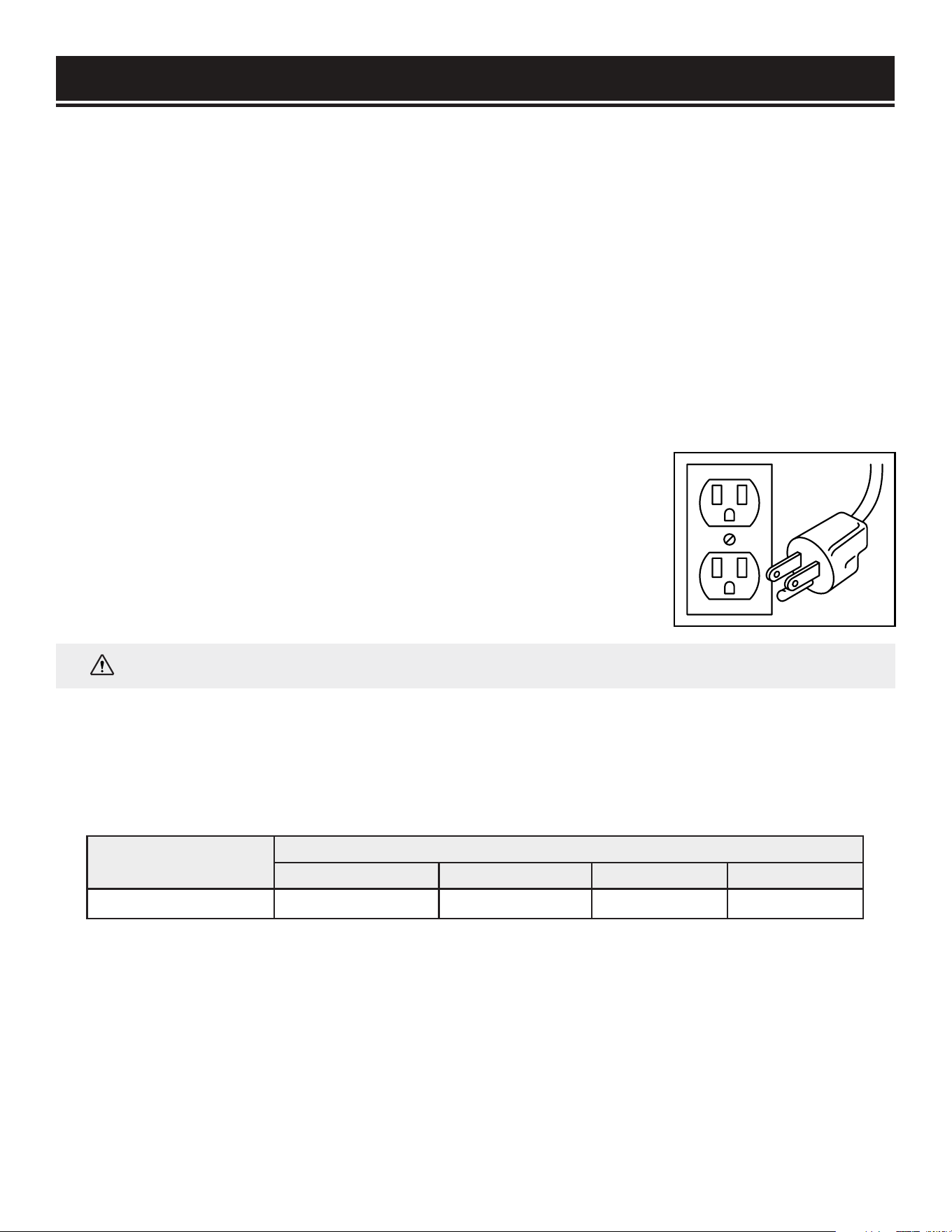
USE ONLY THREE-WIRE EXTENSION CORDS that have three-pronged plugs
and outlets that accept the tool’s plug as shown in Fig. 1. Repair or replace a
damaged or worn cord immediately.
GROUNDING INSTRUCTIONS
IN THE EVENT OF A MALFUNCTION OR BREAKDOWN, grounding provides the path of least resistance for
an electric current and reduces the risk of electric shock. This tool is equipped with an electric cord that has
an equipment grounding conductor and a grounding plug. The plug MUST be plugged into a matching outlet
that is properly installed and grounded in accordance with ALL local codes and ordinances.
DO NOT MODIFY THE PLUG PROVIDED. If it will not fit the outlet, have the proper outlet installed by a
licensed electrician. Make certain that the outlet in question is properly grounded, if you are unsure have a
licensed electrician check the outlet.
IMPROPER CONNECTION of the equipment grounding conductor can result in electric shock. The conductor
with the green insulation (with or without yellow stripes) is the equipment grounding conductor. If repair or
replacement of the electric cord or plug is necessary, DO NOT connect the equipment grounding conductor
to a live terminal.
Fig. 1
WARNING:
This tool is for indoor use only. Do not expose to rain or use in damp locations.
6

SPECIFIC RULES FOR DRUM SANDERS
1. INSPECT THE TOOL. Before operation, check the tool for any damage or missing parts. Make sure all
adjustments are correct and all connections are tight. Do not use the tool if any part is missing or damaged.
Check the conveyor belt to make sure there is no debris or sawdust between components. Never sand with
the sanding drum cover open or safety guards removed.
2. PERSONAL SAFETY. Never put any body parts into the dust port or close to the sanding drum, as serious
injury may occur. Always keep hands at a safe distance from the sanding drum when feeding the workpiece.
3. STANDING POSITION. To avoid serious injury from kickback, do not stand in line with the infeed or
outfeed sides of the sander. Keep your body to the side of the sanding path.
4. INSPECT YOUR WORKPIECE. The sander is designed to sand only natural wood products or man-made
products made from natural wood fiber. Make sure the workpiece is free from nails, knots, screws, stones
or other foreign objects, as they may eject from the sander at a high speed and injure the operator. There
should be no loose knots and as few tight knots as possible in the stock.
5. DEPTH OF CUT. The sander can only remove 1/32 inches (0.8mm) of materials or less in each pass.
Attempting to take greater depth of cut than 1/32 inches could result in kickback that can cause serious
personal injury and machine damage.
6. WORKPIECE DIMENSIONS. To maintain stable operation, do not sand materials shorter than 4-3/4 inches
(120mm) or narrower than 3/4 inches (19mm).
7. WORKPIECE QUANTITY. Never sand two or more workpieces side-by-side. No two workpieces are exactly
the same thickness. One of them may be shot out from the sander at high speed and cause injury.
8. WORKPEICE SUPPORT. Support the workpiece properly during operation. Insufficient support could
cause the workpiece to kick back. Maintain control of the workpiece on both the infeed and outfeed sides of
the sander at all times. Work with another person if necessary to support the workpiece on both ends of the
machine.
9. WORKPIECE FEED RATE. Set the proper feed rate for your purposes. Setting the feed rate too fast may
cause kickback during operation.
10. FEEDING THE WORKPIECE. Allow the sanding drum to reach full speed before feeding the workpiece.
The workpiece can only be fed from the infeed side against the rotation direction of the drum. Carefully hold
the workpiece on the conveyor and ease it into the sander. Do not force feed the workpiece through the
machine. Do not try to back the workpiece from the infeed table.
11. MAKING ADJUSTMENTS. Always turn off the machine and disconnect from the power source before
making adjustments or changing sandpaper.
12. SANDPAPER INSTALLATION. Make sure the sandpaper is attached correctly according to the
instructions. Improperly installed sandpaper could come loose during operation and damage the workpiece
and the machine.
7
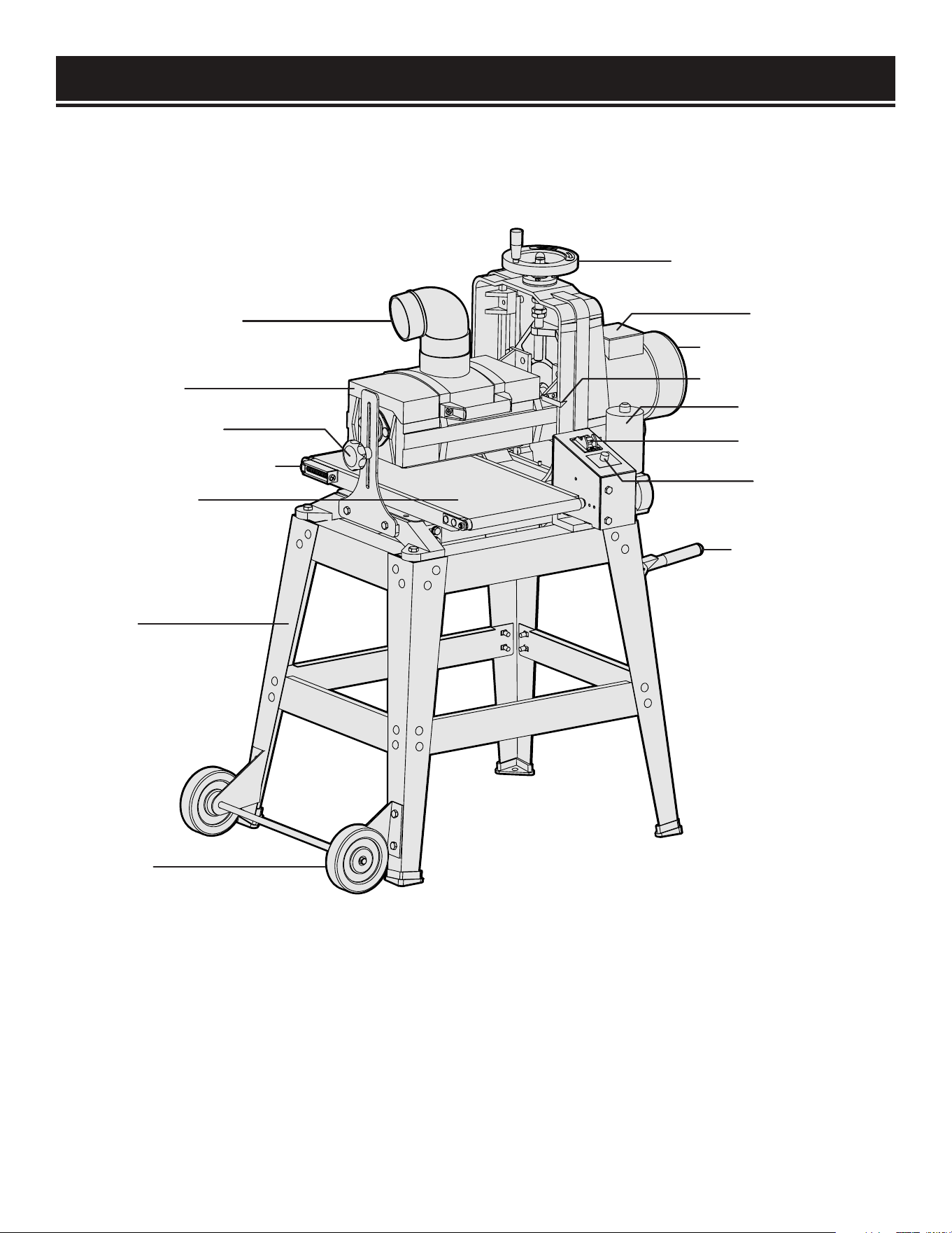
KNOW YOUR DRUM SANDER
Use the diagram below to become familiarized with the components and controls of your drum sander. If
you have any questions or concerns, please contact our Customer Service at (800) 232-1195, M-F 8-5 CST
or email us at [email protected].
Height Adjustment Wheel
Circuit Breaker
Sanding Drum Motor
Cutting Depth Pointer
Conveyer Motor
ON / OFF Switch
Feed Rate Dial
Carrying Handles
Dust Collection Port
Drum Cover
Height Lock Knob
Belt Tracking Adjustment
Conveyor Belt
Stand
Wheels
8
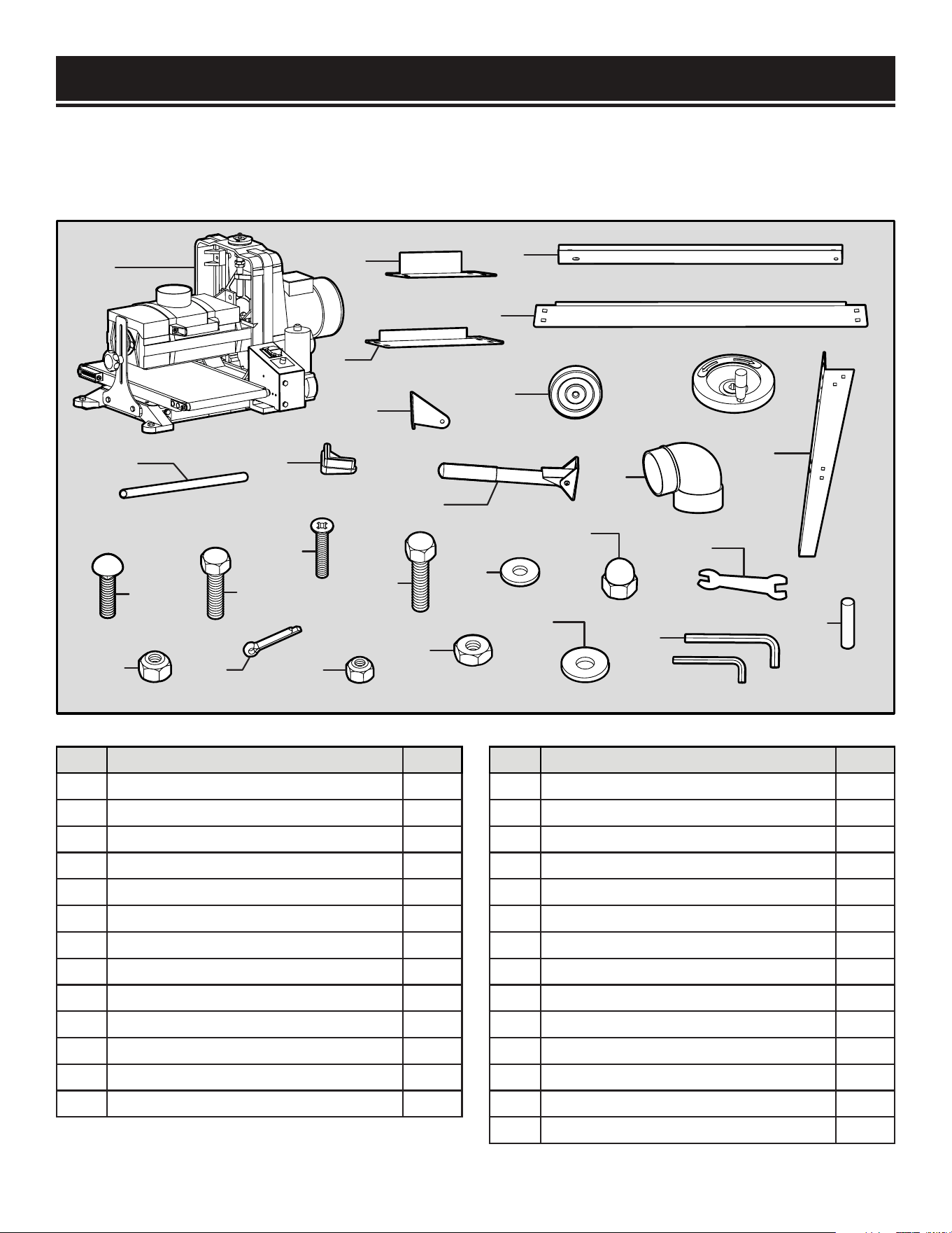
UNPACKING
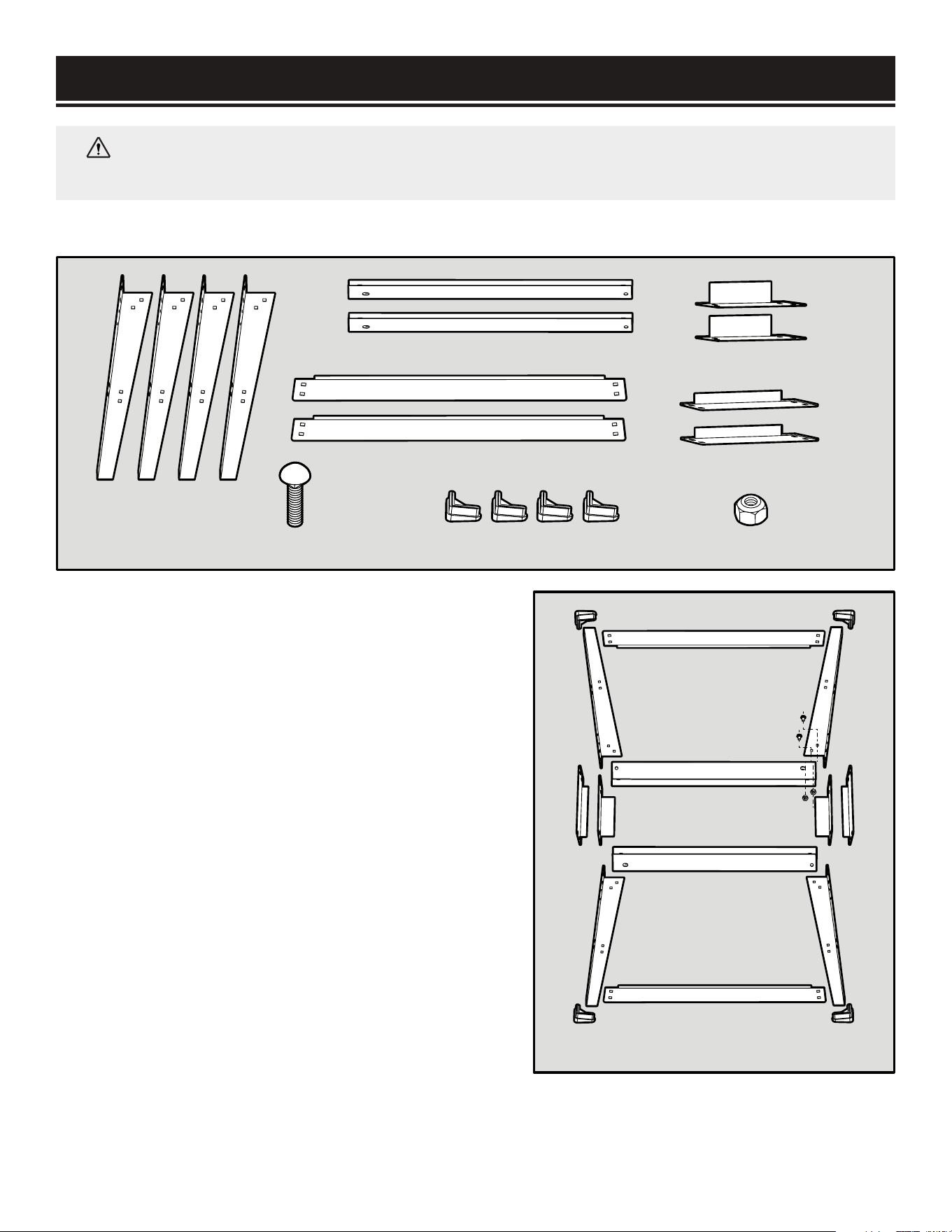
PACKING LIST
Check your packing list against the diagram below. If any part is damaged or missing, please contact
our customer service at (800) 232-1195, M-F 8-5 CST or email us at [email protected].
1
2
3
4
5
6
7
8
9
10
11
12
13
S1
S2
S3
S4
S5
S6
S7
S8
S9
S10
S11
S12
S13
S14
NO. PARTS QTY.
1
Drum Sander Assembly
1
2 Short Top Brace 14-5/8” 2
3 Long Top Brace 17-1/4” 2
4 Short Bottom Brace 20-1/4” 2
5 Long Bottom Brace 23-1/8” 2
6 Legs 4
7 Feet Pads 4
8 Wheel Brackets 2
9 Wheels 2
10 Wheel Axle 1
11 Lifting Handle Assembly 2
12 Height Adjustment Wheel 1
13 Dust Port 1
NO. HARDWARE QTY.
S1 Carriage Bolts M8-1.25 x 12 32
S2 Lock Nuts M8-1.25 36
S3 Hex Bolts M8-1.25 x 16 4
S4 Cotter Pins 4 x 20mm 2
S5 Flat Head Screws M6-1 x 10 4
S6 Lock Nuts M6-1 4
S7 Hex Bolts M10-1.5 x 30 4
S8 Flat Washer 10mm 4
S9 Hex Nuts M10-1.5 4
S10 Acorn Nut M12-1.75 1
S11 Large Washer 12mm 1
S12 Open End Wrench 11/13mm 1
S13 Hex Wrench 5mm, 6mm 2
S14 Holding Pin 1
9
ASSEMBLY
WARNING:
To avoid injury from accidental startups, do not plug in the drum sander until all
assembly and preparation procedures have been completed.
ASSEMBLING THE STAND (FIG. 2)
1. Place the 4 top braces upside down on a flat surface
to form a rectangle.
2. Attach the 4 legs to the top braces using (16)
M8-1.25 x 12 carriage bolts and (16) M8-1.25 lock
nuts. The legs should be on the outside of the braces.
Hand tighten all fasteners.
NOTE: There are two types of corner legs: one type
with handle-mounting holes just below the upper
support mounting holes, the other with wheel-
mounting holes on the bottom of each leg. Make sure
that the short braces connect legs of matching styles.
3. Attach the 4 bottom braces to the lower brace
mounting holes of the 4 legs with the remaining (16)
M8-1.25 x 12 carriage bolts and (16) M8-1.25 lock
nuts. Hand tighten all fasteners.
4. Slide the 4 feet pads onto the bottom of the 4 legs.
5. Turn the stand over, square up the braces and legs,
then fully tighten all fasteners using an adjustable
wrench or ratcheting socket wrench.
Legs (x4)
Long Top Braces (x2)
Long Bottom Braces (x2)
M8-1.25 Lock Nuts (x32)Feet Pads (x4)
Short Top Braces (x2)
Short Bottom Braces (x2)
M8-1.25x12 Carriage Bolts (x32)
Handle Mount Legs
Wheel Mount Legs
Fig. 2
10
ASSEMBLY
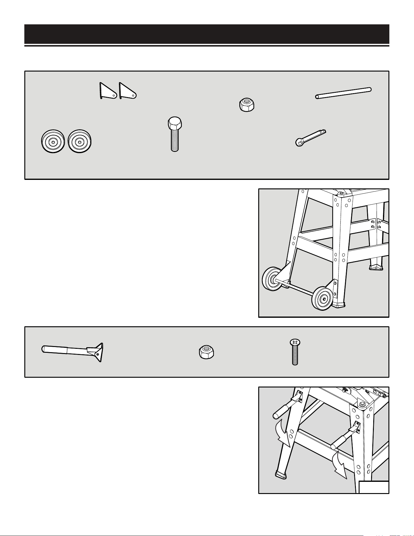
INSTALLING THE WHEELS (FIG.3)
1. Attach the 2 wheel brackets to the 2 wheel-mounting
legs with (4) M8-1.25 x 16 hex bolts and (4) M8-1.25 lock
nuts. Note that the left and right wheel brackets are different
configurations. Tighten the fasteners with a wrench.
2. Slide the wheel axle through the 2 wheel brackets. Then
install the two wheels onto the two ends of the wheel axle.
3. Secure the 2 wheels with the 2 cotter pins by inserting
them through the axle holes and bending back the ends.
INSTALLING THE HANDLES (FIG. 4)
1. Attach the lifting handle assemblies onto the
handle-mounting with (4) M6-1 x 10 flat head screws and
(4) M6-1 lock nuts.
2. Use a Phillips screwdriver to hold the mounting screws
stationary while tightening the locking nuts with a suitable
wrench.
NOTE: The handle should be able to swing up 90 degrees
from the “down” position, but not any farther.
Wheel Brackets (x2)
Wheels (x2)
Wheel Axle (x1)
M8-1.25x16 Hex Bolts (x4)
M8-1.25 Lock Nuts (x4)
Cotter Pins 4x20mm (x2)
Lifting Handle
Assemblies (x2)
M6-1 x 10 Flat
Head Screws (x4)
M6-1 Lock
Nuts (x4)
Fig. 3
Fig. 4
11
ASSEMBLY
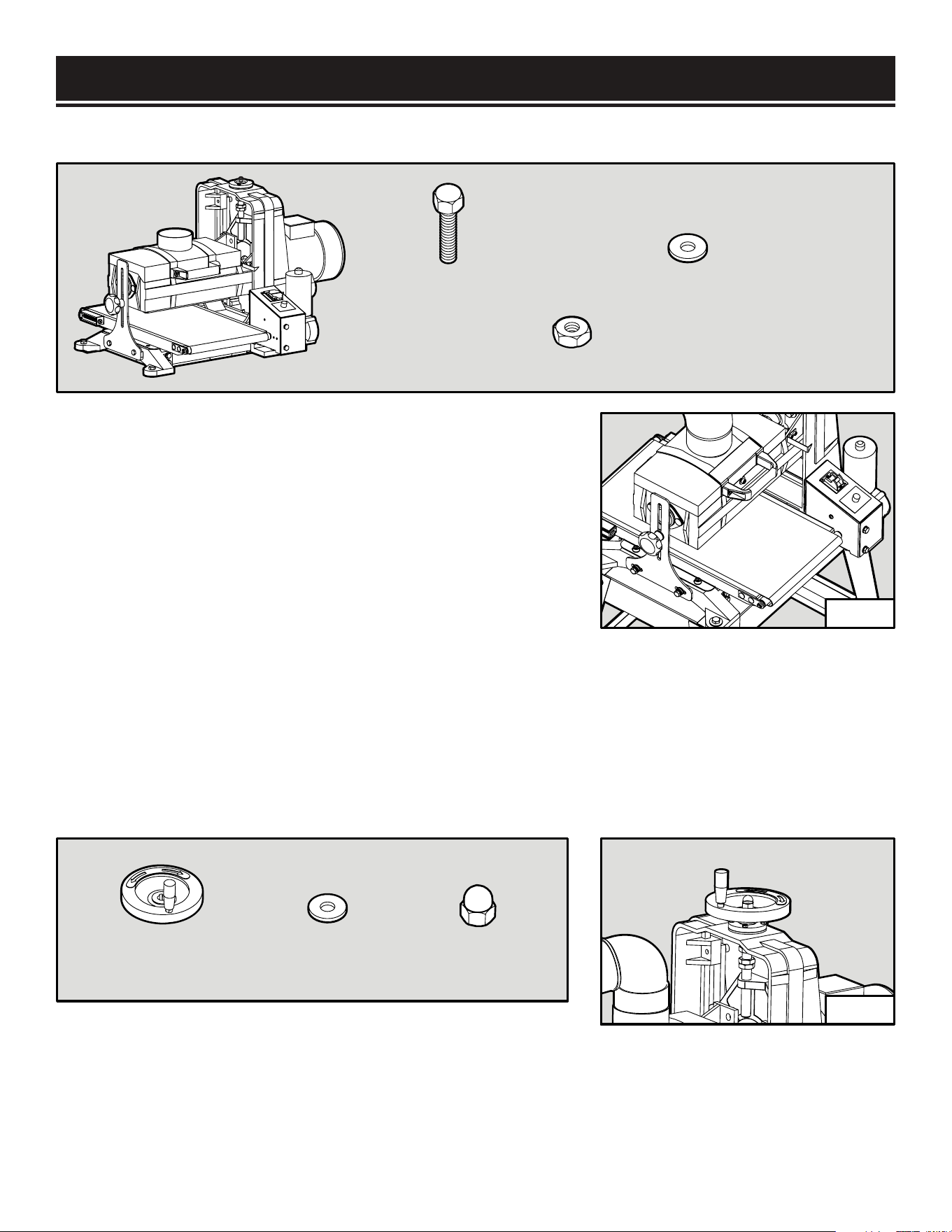
MOUNTING THE MACHINE ONTO THE STAND (FIG. 5)
1. This sander weighs over 150 lbs, so you will need a strong
muscular friend (or a trustworthy foe) to help you lift it up.
Carefully place the sander onto the assembled stand in the
orientation you prefer (the motor side of the sander can be
positioned above the wheels side or the handles side).
2. Align the mounting holes on the base of the machine with
the holes on the stand. Mount the machine in place using (4)
M10-1.5 x 30 hex bolts, (4) 10mm flat washers, and (4)
M10-1.5 hex nuts. Tighten the fasteners using a wrench.
NOTE: If necessary to align the mounting holes, you can
slightly loosen the stand fasteners. Be sure to re-tighten them
after securing the sander assembly.
INSTALLING THE HEIGHT ADJUSTMENT WHEEL (FIG. 6)
Attach the height adjustment wheel onto the screw on top
of the sander. Mount the 12mm large washer and M12-1.75
acorn nut on top of the wheel and tighten the nut.
Drum Sander
Assembly (x1)
M10-1.5 x 30
Hex Bolts (x4)
10mm Flat
Washers (x4)
M10-1.5 x 30
Hex Nut (x4)
12mm Large
Washer (x1)
M12-1.75 Acorn
Nut (x1)
Height Adjustment
Wheel Assembly (x1)
Fig. 5
Fig. 6
12
ASSEMBLY
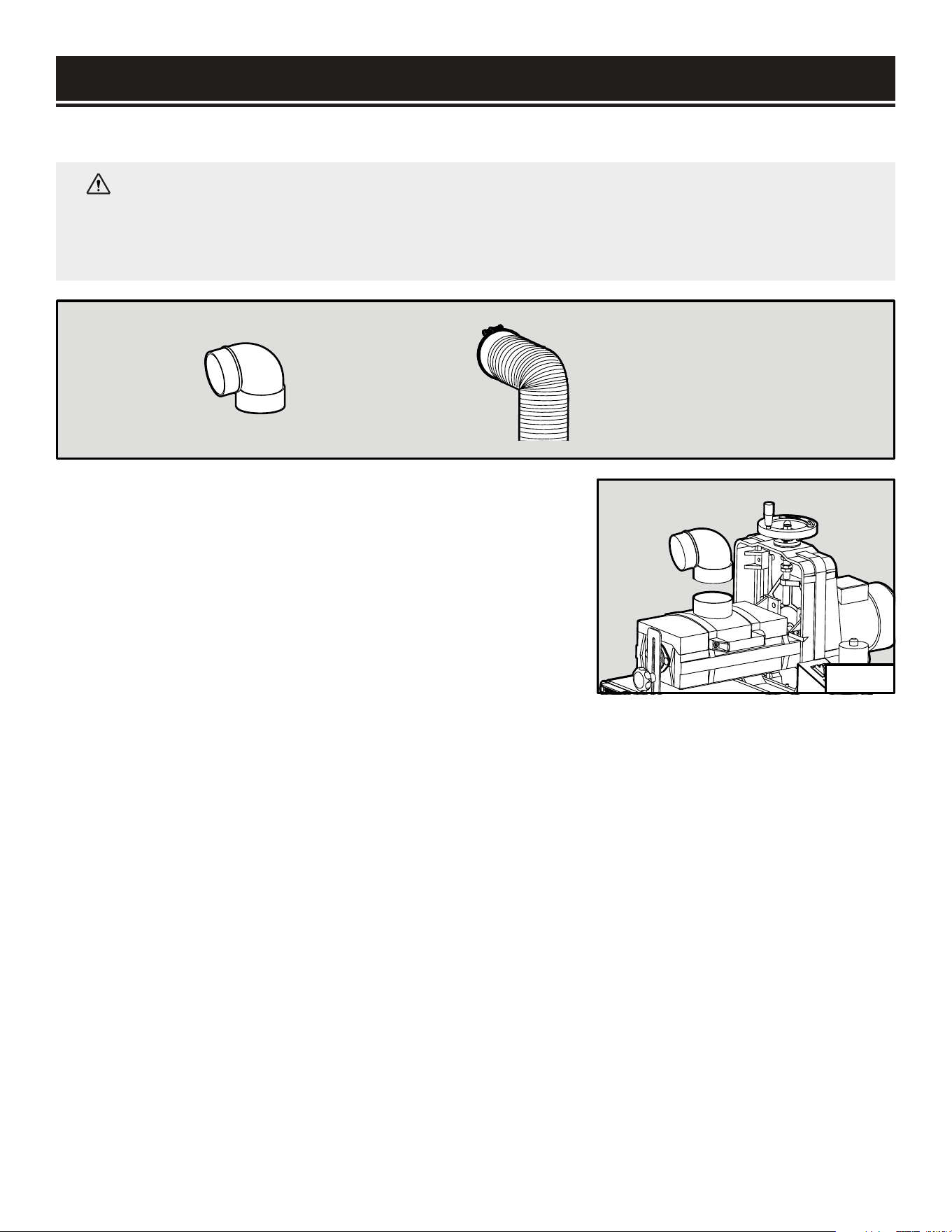
MOUNTING THE DUST PORT (FIG. 7)
WARNING:
Sanding produces a lot of dust that could be harmful to your health. Always
operate using a dust collection system and approved face mask to minimize the risk of lung
damage from dust inhalation. DO NOT operate the drum sander without an adequate dust
collection system.
1. Install the dust port onto the drum cover.
2. Fit a 4-inch dust hose (not included) over the dust port and
secure it in place with a hose clamp (not included). A tight fit
is necessary for proper dust collection performance.
3. Connect the dust hose to your dust-collection system of
choice.
NOTE: The dust port on your sander is compatible with the
WEN 28200 10 ft. dust hose and the WEN 28221 20 ft. dust
hose, available at wenproducts.com.
Dust Port (x1)
Dust hose and hose clamp (x1)
(not included)
Fig. 7
13
Grit Size Coarse Level Characteristics and Uses
36 Extra Coarse Maximum stock removal, abrasive planning, paint removal
60-80 Coarse Stock removal, surfacing, end grain surfacing, planer mark removal
100-120 Medium End grain smoothing, light surfacing
150-180 Fine Finish sanding, surface preparation, thin stock dimensioning
220 Very Fine Finish sanding
SANDPAPER INSTALLATION
SANDPAPER GRIT SIZE
Your drum sander comes with 80-grit sandpaper pre-installed. The grit size of sandpaper determines
the finish of the surface. The lower the grit number, the coarser the sandpaper and the rougher the
sanded surface. The higher the grit number, the finer the sandpaper and the smoother the sanded
surface. Typically, begin sanding with a coarse grit sandpaper and progressively work through finer
grits until the desired finish or thickness is achieved.
Experiment with different sanding grits on a scrap workpiece to determine the result of the sanded
surface. Refer to the chart below for the characteristics and uses associated with different sandpaper
girt sizes.
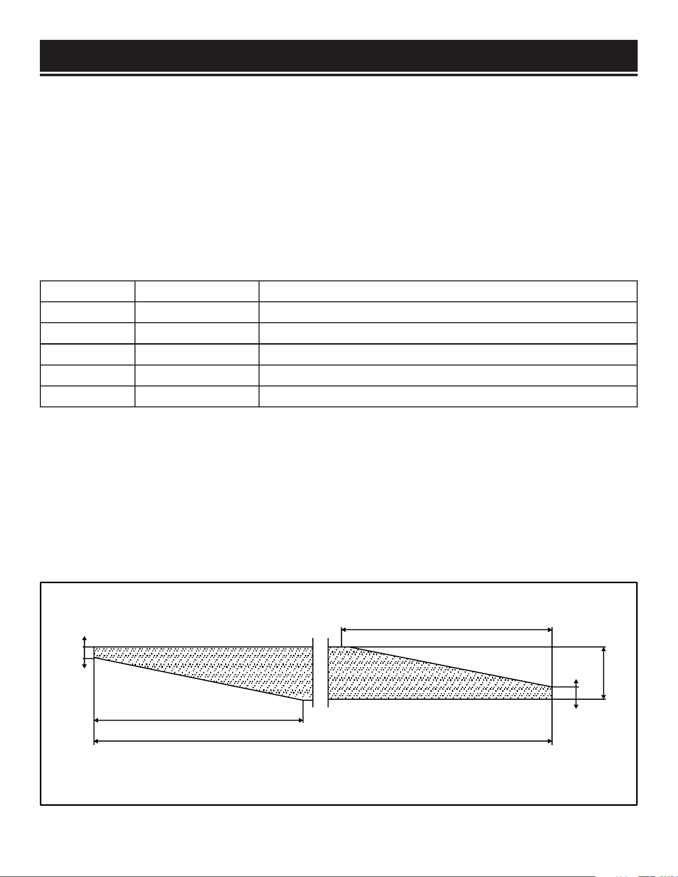
SANDPAPER PREPARATION
Sandpaper for drum sanders are trimmed specifically to properly wrap around the sanding drum. You
can find pre-cut drum sander sandpaper that is ready to use and requires no measuring or trimming.
You can also purchase a 3-1/4 inch (82mm) wide sandpaper roll and trim it using the diagram below
or your existing sandpaper as a template.
NOTE: Your friends at WEN offer pre-cut sandpaper in different grit sizes specifically for your drum
sander. Sandpaper can be ordered from wenproducts.com by searching the model number 65910.
14-7/8" (378mm)
3-1/4" (82mm)
1/8" (3.5mm)
9/16" (15mm)
12-7/8" (326mm)
62-1/2" (1585mm)
14
SANDPAPER INSTALLATION
WARNING:
To avoid injury from accidental startups, always ensure that the tool is switched
OFF and unplugged from the power supply before making adjustments.
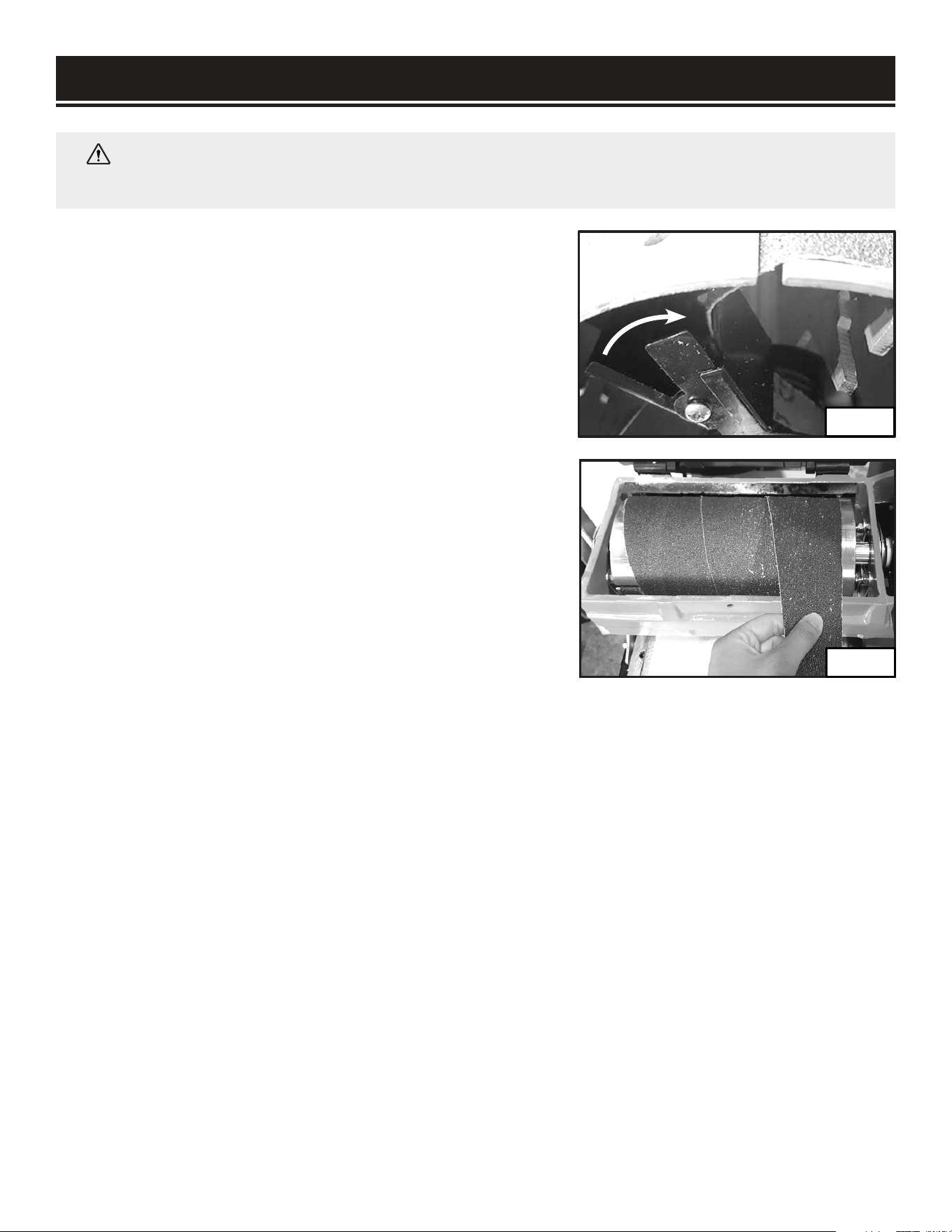
REMOVING EXISTING SANDPAPER (FIG. 8 & 9)
1. Disconnect the drum sander from the power supply.
2. Using a hex wrench, remove the socket-head screw and
washer securing the drum cover. Lift up the cover to expose
the sanding drum.
3. Roll the sanding drum until the slot on the right side of
the drum is on top. Reach under the right lip of the drum to
locate the spring clamp (Fig. 8).
4. Push forward the clamp to release the tension on the
sandpaper. Slide out the end of the sandpaper from the slot.
5. Start unwinding the sandpaper from the drum (Fig. 9)
until you come to the clamping device on the left side of the
drum.
6. Push the clamping device on the left of the drum to
release the grip on the sandpaper.
7. Remove the sandpaper.
Fig. 8
Fig. 9
15
PREPARATION
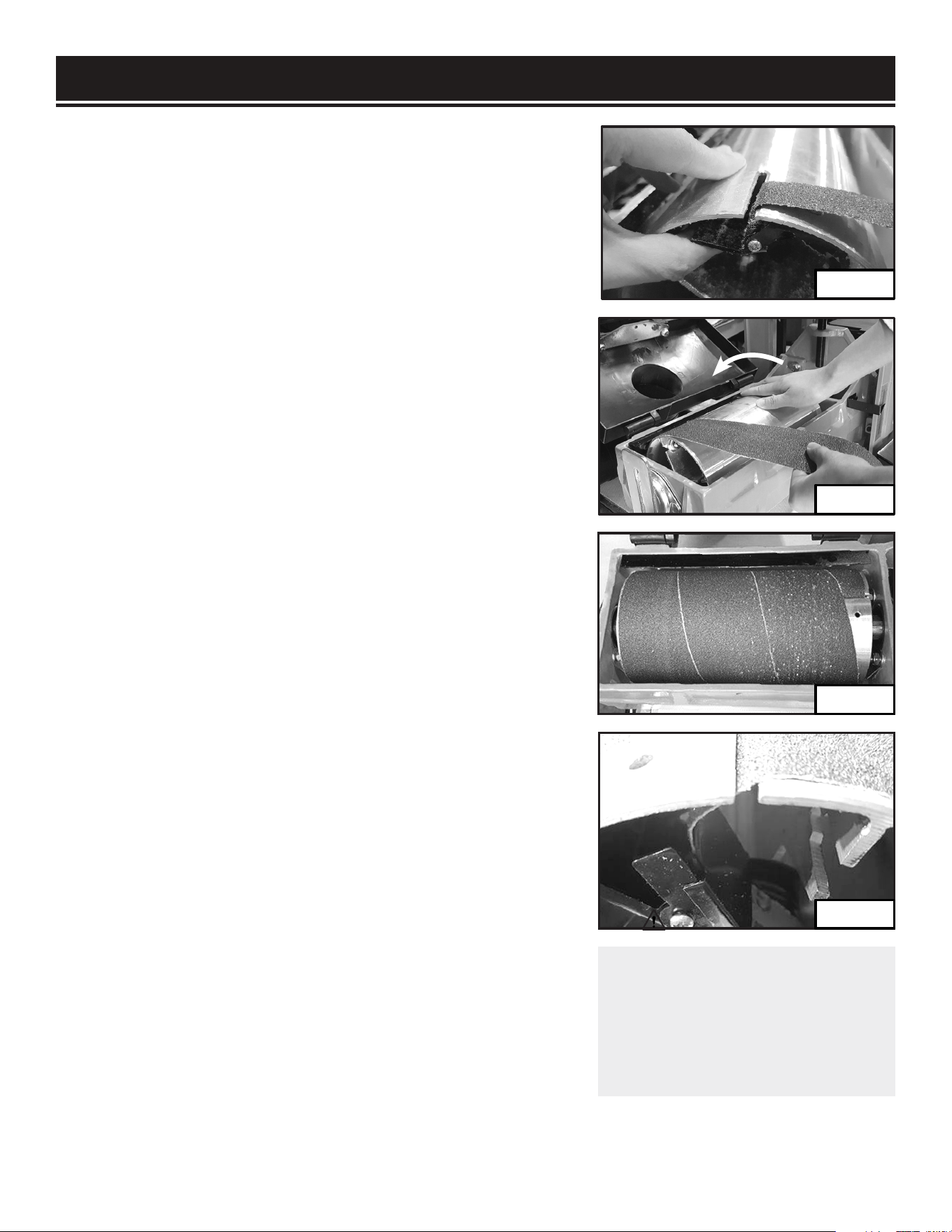
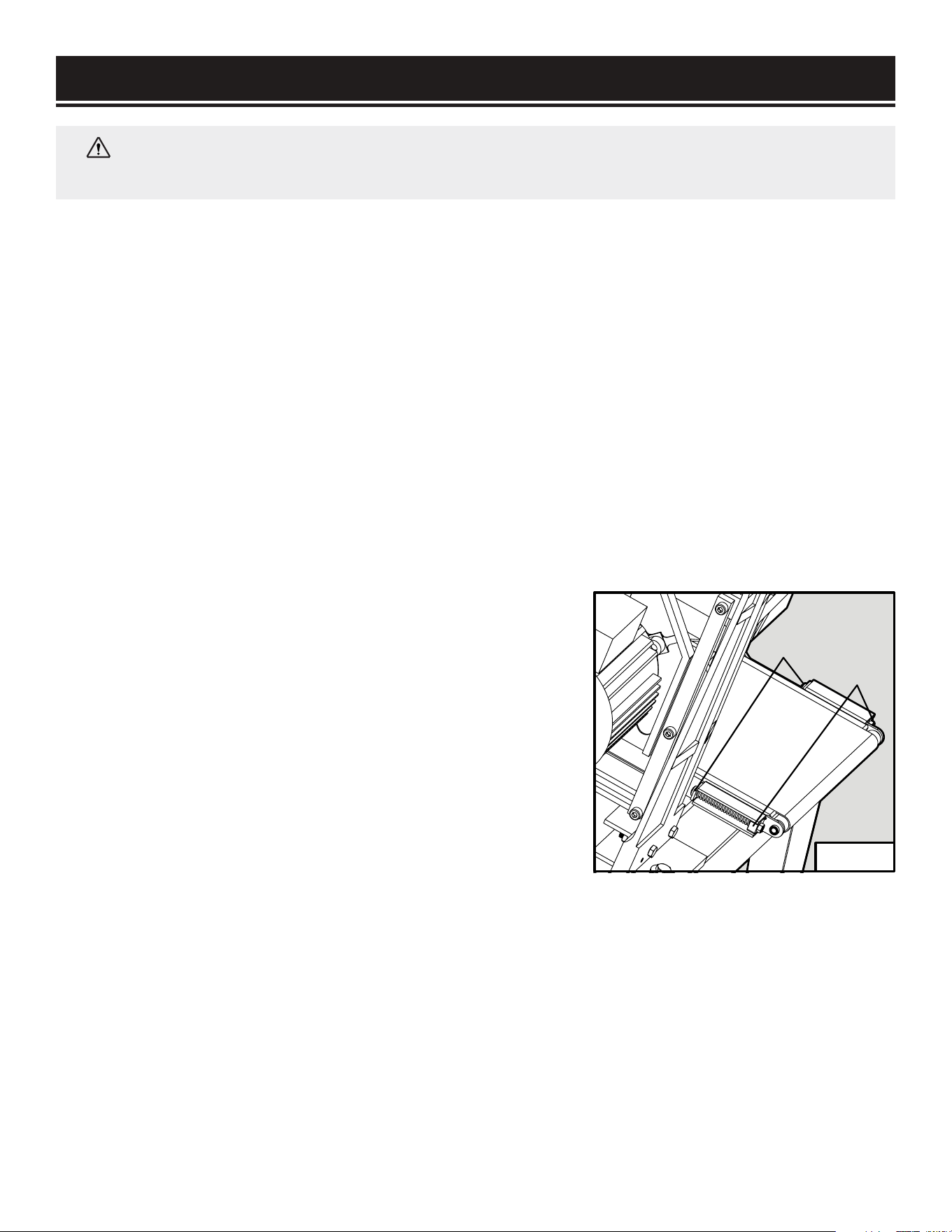
INSTALLING NEW SANDPAPER (FIG. 10-13)
1. Roll the sanding drum until the slot on the left of the drum
is on top. Reach under the left lip of the drum to locate the
spring clamp.
NOTE: Align the directional arrows printed on the bottom of
sandpaper with the drum’s rotation direction.
2. Lift the clamping device and insert the end of the
replacement sandpaper into the slot (Fig. 10). Push the
sandpaper so that about 1 inch of sandpaper is loaded to
ensure enough grip. Align the left side of the sandpaper with
the left lip on the drum.
3. Release the left clamping device to hold the sandpaper
in place. Pull on the sandpaper to make sure the end of the
sandpaper strip has been securely clamped. If the strip comes
loose, repeat steps 1 and 2.
4. Use your right hand to roll the drum away from you and use
your left hand to apply reasonable tension on the sandpaper
while wrapping the sandpaper onto the drum (Fig. 11). Make
sure that the sandpaper strip remains tight as you wrap it.
IMPORTANT: DO NOT overlap the sandpaper. The sandpaper
should be flush or slightly gapped in between.
5. Once the drum is completely wrapped (Fig. 12), keep
tension on the sandpaper and insert the remaining end of the
strip into the slot on the right of the drum.
6. Press the clamp forward until the slot on the clamp is in line
with the slot on the drum. Insert the end of the sandpaper into
the slot and through the jaw of the clamp (Fig. 13).
NOTE: It may help to insert a holding pin through the hole on
the sanding drum and the clamp to hold the clamp in place as
you are inserting the sandpaper. Remove pin after sandpaper
installation afterwards.
7. Release the clamp to secure the end of the sandpaper.
Check that the sandpaper is properly installed and is wrapped
tight against the drum.
8. Close the drum cover and replace the washer and cap screw.
WARNING:
Make sure that the
sandpaper is correctly installed
and tightened onto the sanding
drum before connecting the
machine to the power supply.
Fig. 10
Fig. 11
Fig. 12
Fig. 13
16

PREPARATION
PLANNING YOUR WORK
Planning your work before operation will help to save time and minimize setups. Group your
workpiece by thickness and grit requirements. Work through each required sanding grit from the
thickest to the thinnest material. Then, change to a finer grit sandpaper and work through the
process again.
WARNING:
To avoid injury from accidental startups, always ensure that the tool is switched
OFF and unplugged from the power supply before making adjustments.
INTRODUCTION
The drum sander is a machine designed to sand wooden workpieces to a desired thickness and
smoothness. Before adjusting and operating the machine, it is important to know that drum sanding
is different from thickness planing. Drum sanding can only remove material in increments of 1/32
inch (0.8mm) or less, depending on the sanding grit, material hardness, sanding width, etc. The drum
sander is not suitable for quick bulk material removal. Forcing your drum sander to remove too much
material too fast will cause damage to your machine and the workpiece.
WORKPIECE INSPECTION
This drum sander is intended for sanding natural and man-made wood materials. This machine
cannot sand other materials such as metal, glass, stone, tile, etc. Make sure to inspect all workpieces
before operation and refer to the list below for materials that you should avoid or take extra care with.
FOREIGN OBJECTS. Foreign objects such as nails, staples, dirt, rocks, etc. are often embedded in wood. The
objects may cause kickback that can hit the operator and damage the machine. Remove those foreign objects
before operation.
LARGE OR LOOSE KNOTS. Choose workpieces that do not have large or loose knots. Large knots may cause
kickback and damage the machine. Loose knots in stock can become dislodged during sanding operations.
WOOD SPECIES WITH TOXIC PROPERTIES. Wood species such as the rosewood family (e.g. cocobolo) have toxic
properties that may result in allergic reactions. Even with dust control, you may inhale small airborne particles and
possibly suffer an allergic reaction.
HIGHLY RESINOUS SPECIES. Highly resinous species tend to quickly clog or load up sandpaper easily. This
includes some common pine species. It is almost impossible to clear the sandpaper of the pitch and sawdust from
those species of wood. Avoid sanding those wood species or make sure to replace sandpaper often.
WET OR GREEN STOCK. Wood stock with a moisture content over 20% causes excessive wear on the sandpaper
and motors as you’re sanding. This may increase the risk of kickback and result in a poor surface finish. Use stock
with moisture content below 20%.
EXCESSIVE WARPING. Do not sand workpieces with excessive warping or twisting as they are unpredictable and
difficult to hold stable. DO NOT sand workpieces with excessive warping.
Continues on page 18
17
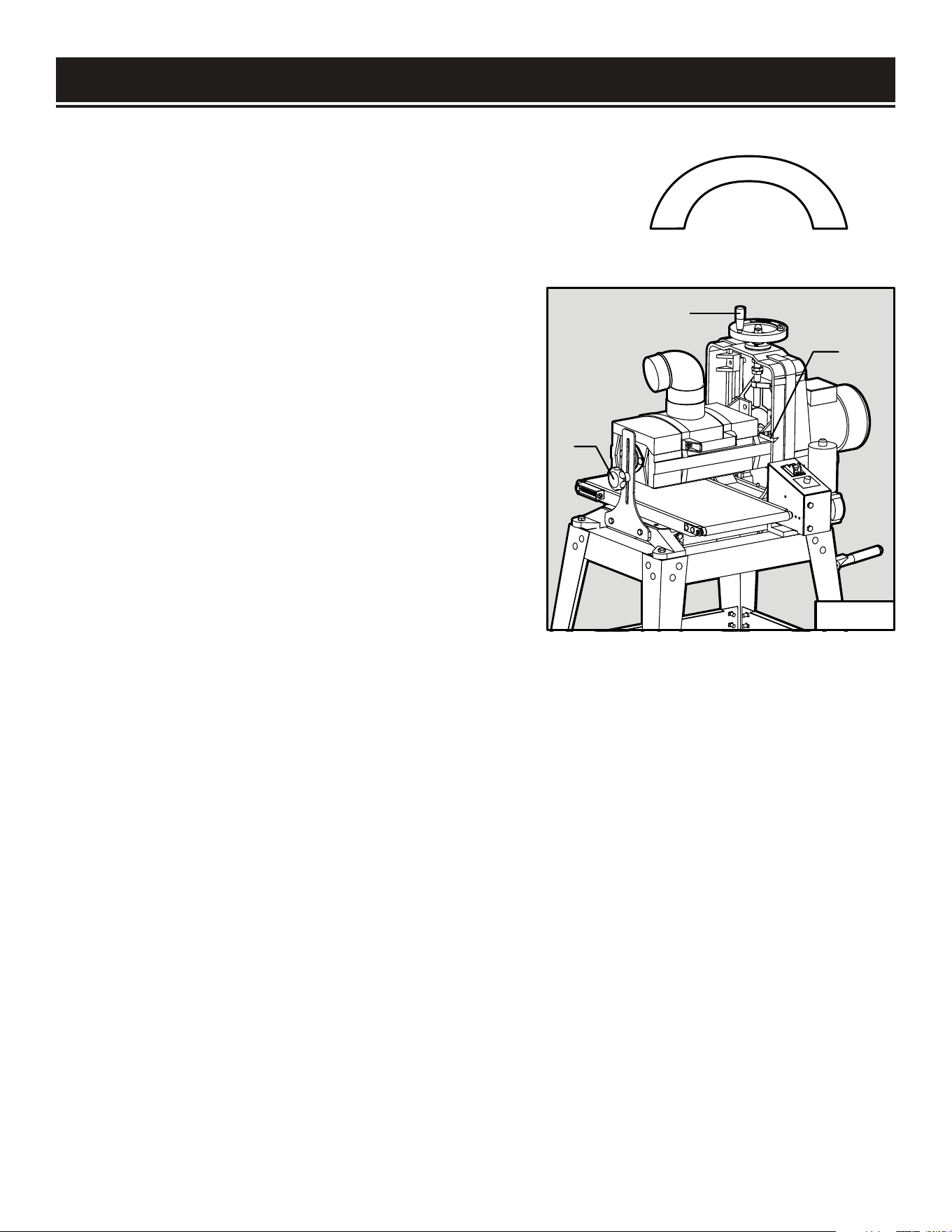
PREPARATION
MINOR WARPING. When sanding workpieces with minor warping,
make sure the concave side is downward, facing the conveyor
belt. Check that the workpiece can be stable and well supported.
Do not place the workpiece with the convex side down, as it will
wobble during operation and cause kickback and possible injury.
ADJUSTING THE DEPTH OF CUT (FIG. 14)
The depth of cut of your drum sander is the amount
of material that is removed by the sanding drum in
one pass. The proper depth of cut depends on many
variables, including the feed rate, hardness of the
material and width of the material. For a smoother
result, a smaller depth of cut is always recommended.
IMPORTANT: You should never remove more than
1/32 inch (0.8mm) of material in one pass.
The depth of cut can be adjusted by rotating the
height adjustment wheel (Fig. 14 - 2). Rotating the
handwheel 1/4 turn adjusts the depth of cut by 1/32
inch. Generally, a 1/4 turn of the handwheel
1
2
3
Convex
Concave
Fig. 14
18
(1/32” depth of cut) per pass is acceptable for coarser grits or softer woods. A 1/8 turn of the
handwheel (1/64” depth of cut) is recommended for finer grits or harder woods.
TO ADJUST THE DEPTH OF CUT:
1. Loosen the elevation lock knob (Fig. 14 - 1).
2. Rotate the height adjustment wheel (Fig. 14 - 2). Rotating the handwheel clockwise raises the
sanding drum and rotating the handwheel counterclockwise lowers the sanding drum. A 1/4 turn
adjusts the depth of cut by 1/32”.
3. Use the depth pointer (Fig. 14 - 3) to check the cutting depth. When the proper depth of cut has
been set, firmly tighten the lock knob to secure the sanding drum in place.
4. For the best result, test on a scrap piece of wood of similar material and adjust the cutting depth
accordingly.
PREPARATION
ADJUSTING THE FEED RATE (FIG. 15)
The feed rate is the speed that the conveyor belt
travels to deliver the workpiece through the sanding
drum. Setting the feed rate too fast may overload
the motor, while setting the feed rate too slow may
burn the surface of the workpiece. In general, a
wider or harder workpiece and finer grit sandpaper
will require a slower feed rate.
Rotate the feed rate dial (Fig. 15 - 1) to adjust the
conveyor belt feed rate. Rotating the feed rate dial
WARNING:
Do not attempt to plug in or operate your tool until the entire operator’s manual
has been read and understood. Make sure that the machine is assembled and setup properly.
Failure to do so could result in personal injury and damage to the tool.
WARNING:
Loose hair, clothing, or jewelry could get caught in machinery and cause
serious personal injury. Keep these items away from moving parts at all times to reduce the
risk of injury.
WARNING:
Damage to your eyes and lungs could result from using this machine without
proper protective gear. Always wear safety glasses and a respirator when operating this
machine.
1
Fig. 15
19
clockwise increases the feed rate and rotating it clockwise decreases the feed rate. For the best
result, test on a scrap piece of wood of similar material and adjust the feed rate accordingly.
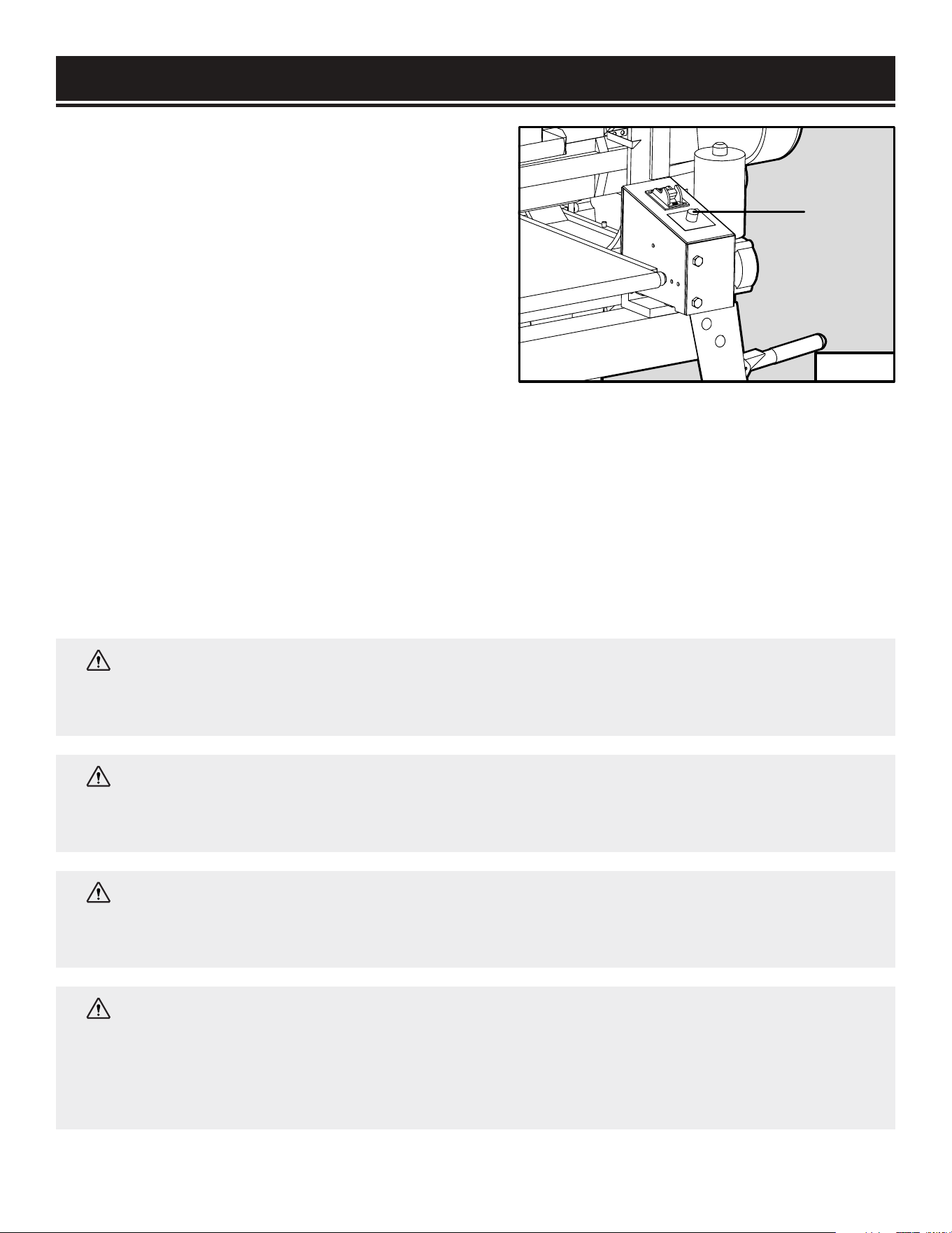
MOTOR OVERLOAD PROTECTOR
Your drum sander is equipped with an overload protector that shuts down the machine when it is
overloaded to protect the motor. The machine can overload when the depth of cut is too much or
the feed rate is too high. When an overload happens, wait for the motor to cool down. Press the red
circuit breaker on the box above the motor to reset. Reduce the depth of cut and feed rate, then try
again.
WARNING:
This machine creates a lot of dust. Inhaling said dust on a regular basis can
cause permanent respiratory illness. Minimize your exposure by wearing a respirator and
using a dust collector. If you do not use some method of dust extraction or collection, the
motor could overheat and fail. Failure to use some method of dust extraction or collection will
void the warranty.

PREPARATION
1. Make sure the drum sander is switched off and disconnected from the power supply. Connect the
sander to a suitable dust collection system before operation.
2. Inspect the workpiece and make sure it is acceptable for the sanding operation. Make sure that the
correct sandpaper grit is selected and the sandpaper is properly installed onto the drum.
3. Lay the workpiece flat on the conveyor belt below the sanding drum.
4. Loosen the height lock knob (Fig. 14 - 1) and turn the height adjustment wheel (Fig. 14 - 2) to
lower the sanding drum until it lands on the top surface of the workpiece. This will allow the sander
to take off just the top surface of the workpiece with the first pass. Remove the workpiece from the
conveyor belt and set it aside.
5. Plug in and turn on the sander. Adjust the conveyor feed rate to suit the sanding operation.
6. Stand to the side of the conveyor belt to avoid the risk of kickback. Allow the sanding drum to
reach full speed before inserting the workpiece.
7. Place the workpiece onto the infeed side of the conveyor belt, flush against the belt and parallel to
the direction of the belt’s movement. Hold the workpiece on the conveyor and carefully ease it into
the sander. Be careful not to get your hand or any body parts close to the sanding drum.
8. Once the sanding drum has control of the workpiece, step to the side of the outfeed conveyor belt
and support of the workpiece as it leaves the sanding drum. Do not stand in line with the sanding
path.
NOTE: Do not apply upward or downward pressure when supporting or guiding the workpiece
through the sander. Doing so may induce snipe, where the sander drum digs into the workpiece.
9. Rotate the workpiece horizontally 180 degrees and pass it through the sander again, without
changing the depth of cut setting. This will create a even finish on your sanding surface.
10. Increase the depth of cut by the correct amount (must be less than 1/32”), then repeat steps
7–10 with progressively finer sandpaper grits until you have produced the desired results. Always
use the correct depth of cut and feed rate. Taking too heavy of a cut or using too fast a feed rate may
cause kickback.
NOTE: Keep in mind that as you change to finer grit size, the feed rate needs to be reduced
accordingly.
11. When the sanding operation is complete, turn off the drum sander and unplug the power cord.
Wait for the drum to come to a complete stop before leaving the work area.
20
ADJUSTMENTS
WARNING:
To avoid injury from accidental startups, always ensure that the tool is switched
OFF and unplugged from the power supply before making adjustments.
The following settings should be correctly adjusted from the factory. However, they may need to be
checked and adjusted to ensure optimal sanding performance. Refer to the sections below to adjust
the following settings.
• Conveyor belt tension and tracking (page 21)
• Elevation tension screw adjustment (page 22)
• Conveyor belt to drum alignment (page 23)
• Pressure roller adjustment (page 23)
• Elevation stop adjustment (page 24)
CONVEYOR BELT TENSION ADJUSTMENT (FIG. 16)
The conveyor belt tension should be properly adjusted to ensure safe operation and protect the belt
from damage. The belt tension can be adjusted by rotating the tensioning screws on both sides of the
conveyor table. To adjust the belt tension:
1. Turn off and disconnect the machine from the power
source.
2. Release the belt tension equally on both sides of the
table by holding the hex nuts (Fig. 16 - 1) in place while
rotating the tensioning screws (Fig. 16 - 2) counterclockwise.
Position the belt in the center of the rollers.
3. Adjust the tensioning screws so that the end of both
tensioning screws extend about 1/4” beyond the hex nuts
(Fig. 16 - 1).
4. To tighten the belt tension, rotate the tensioning screws
clockwise in small increments until the belt no longer
slips on the rollers. To loosen the belt tension, rotate the
tensioning screws counterclockwise.
1
2
Fig. 16
21
ADJUSTMENTS
CONVEYOR BELT TRACKING ADJUSTMENT
The conveyor belt should track in the center of the conveyor table. Occasionally check the belt
tracking by running the conveyor belt at high speed for a few minutes. If the belt shifts to one side or
the other, the belt tracking needs to be adjusted.
NOTE: Do not allow the belt to track off the rollers as this may damage the belt.
1. If the belt tracks to the left (viewing from the infeed side), tighten the left side tensioning screw by
rotating it clockwise while holding its nut in place. This will make the belt shift to the right side.
2. If the belt tracks to the right (viewing from the infeed side), tighten the right side tensioning screw
by rotating it clockwise while holding its nut in place. This will make the belt shift to the left side.
3. Let the conveyor belt run for a few minutes to check the belt tracking. Re-adjust as necessary.
NOTE: The tracking adjustments may not be apparent immediately. Make small corrections of
approximately 1/4 turn increments to the tensioning knob and evaluate the results. Re--adjust as
necessary until the belt is tracking properly.
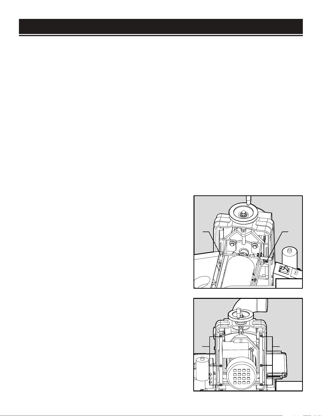
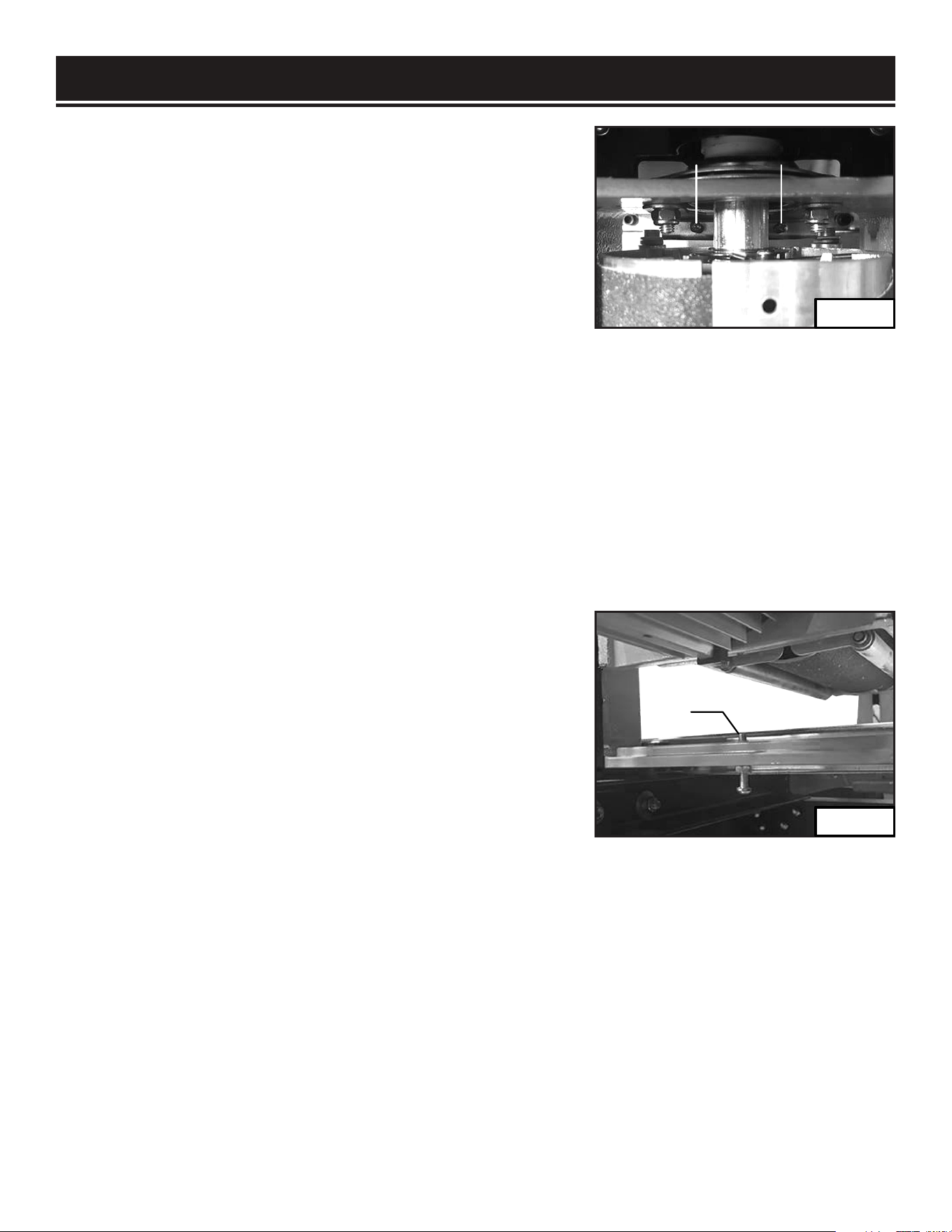
ADJUSTING TENSION SCREWS (FIG. 17 & 18)
The six height adjustment tension screws on the height
adjustment wheel side of the sander apply pressure to the
sliding mechanism of the sanding head. The tightness of
the screws can be tuned for accurate height adjustments.
If the screws are too loose, the drum will deflect during
operation, causing an uneven sanded surface. If the
screws are too tight, adjusting the height of the sanding
drum will be difficult, causing excessive wear on the height
adjustment system.
1. Turn off and disconnect from the power source.
2. Loosen the two center lock nuts on both sides of the
frame (Fig. 17 - 1).
3. Step to the motor side of the sander. Loosen or
tighten the 6 cap screws (Fig. 18 - 1) evenly in 1/4 turn
increments. Rotate the height adjustment wheel to test
the sanding head movement. Adjust the screws until the
desired fit and smoothness is achieved.
4. Re-tighten the two center lock nuts (Fig. 17 - 1).
11
11
Fig. 17
Fig. 18
22
ADJUSTMENTS
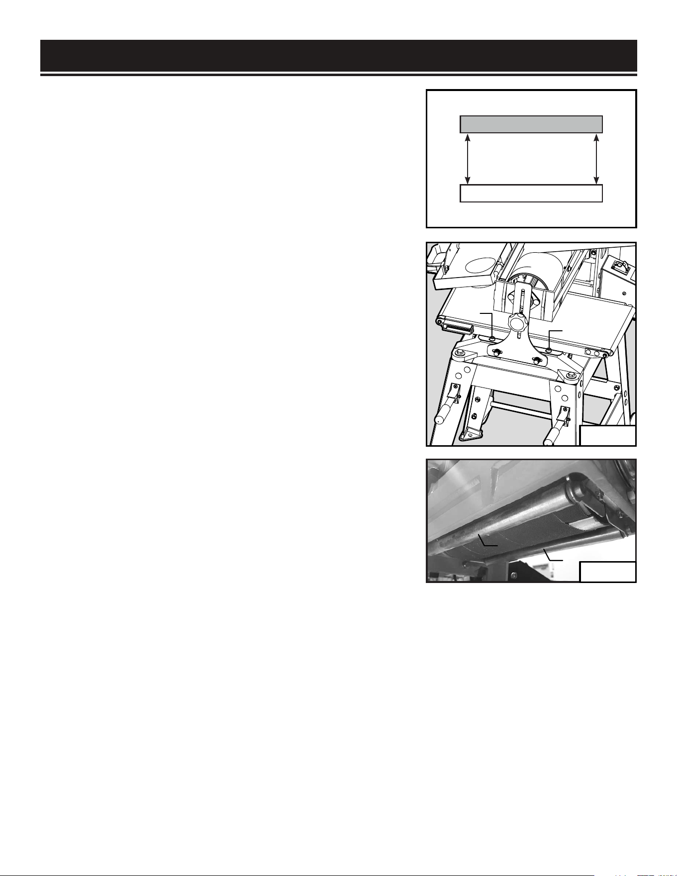
BELT TO DRUM ALIGNMENT (FIG. 19 & 20)
To achieve an even sanding result, the sanding drum and
conveyor belt should be parallel with each other. To check the
belt to table alignment:
1. Make sure the height adjustment tension screws are
properly adjusted. Otherwise the testing results may not be
accurate.
2. Prepare a planed board about 2” thick and 8 - 10” wide.
Make sure the thickness on both ends and sides of the board is
even.
3. Turn on the machine. Feed the board through the sander to
take several light cuts from the top surface of the board.
4. Measure the thickness of the left edge and right edge of the
board. The difference between the two edges should be less
than 0.05”. If it is greater than 0.05”, follow the steps below to
correct it.
5. Remove the two cap screws (Fig. 20 - 1) on the side of the
conveyor table that produces a thicker sanding result. Slide
a metal shim (not included) between conveyor table and the
frame to slightly elevate the conveyor table to reduce the
sanding thickness on that side.
6. Tighten the cap screws to secure the conveyor table.
7. Repeat steps 2 to 6 as necessary until the alignment
between the conveyor belt and drum is within 0.05” difference.
ADJUSTING PRESSURE ROLLER (FIG. 21 & 22)
There are two pressure rollers (Fig. 21 - 1) on each side of the sanding drum. The rollers extrude
slightly below the bottom of the drum in order to press the workpiece against the conveyor belt as it
passes through the sander.
The pressure on the rollers is controlled by the springs and adjustment screws that can be accessed
from the inside of the drum housing. If the roller pressure is too high, kickback and snipe may occur.
If the roller pressure is too low, the workpiece may slip on the conveyor belt. To adjust the pressure
of the rollers:
Sanding Drum
Conveyor Belt
Parallel
Left
Right
1
1
Fig. 19
23
1
1
Fig. 21
Fig. 20
ADJUSTMENTS
1. Turn off and disconnect the machine from the power source.
2. Remove the screw and washer securing the drum cover and
lift the cover open.
3. There are two screws (Fig. 22 - 1) on both ends of the drum.
To increase the roller pressure, evenly tighten all four Phillips
screws by rotating them clockwise in small increments. To
decrease the roller pressure, evenly loosen all four Phillips
screws in small increments.
4. To test the adjustments, turn on the machine and sand a scrap piece of workpiece. If the workpiece
slips on the conveyor belt, increase the pressure by rotating the four screws one turn clockwise.
If the workpiece tends to kick back, reduce the pressure by rotating the four screws one turn
counterclockwise.
5. Repeat until roller pressure has been properly adjusted. Close the drum cover and replace the
washer and cap screw.
ADJUSTING THE STOP SCREW (FIG. 23)
The height adjustment stop, controlled by the protrusion of
the Phillips head screw through the bottom of the frame,
prevents the sanding drum from contacting the conveyor belt.
If necessary, re-adjust the height adjustment stop screw as
follow:
1. Turn off and disconnect the machine from the power source.
2. Loosen the height adjustment lock knob and raise the
sanding drum using the height adjustment wheel.
3. Loosen the hex nut on the stop screw and adjust the height of the screw (Fig. 23 - 1) to protrude
above the frame higher than 1/4 inch.
4. Tighten the hex nut and lower the sanding drum until the motor mount frame touches the top of
the stop screw.
5. Check that the bottom of the sanding drum is at least 3/16” above the surface of the conveyor belt.
If the distance is too close, repeat the steps above to re-adjust as necessary.
11
1
Fig. 22
Fig. 23
24

MAINTENANCE
DAILY INSPECTION
For optimum performance, inspect the machine before every use. Check the following before each
operation.
• Loose mounting fasteners - tighten all fasteners
• Loaded, damaged, or worn sandpaper - clean or replace sandpaper
• Dirty or damaged conveyor belt - clean or replace conveyor belt
• Damaged wires, power cord or faulty switch - replace faulty parts immediately
GENERAL CLEANING
Keep your drum sander clean. Vacuum accumulated sawdust from working parts and wipe clean with
a dry cloth. To clean resin buildup on the sanding drum, remove the sandpaper strip and clean using
a resin-dissolving cleaner of your choice. Clean the conveyor belt with soapy water and wipe dry with
a clean towel.
WARNING:
To prevent serious injury from accidental operation, always turn off and
disconnect the machine from power source before installation, cleaning and maintenance
operations.
WARNING:
Use caution when performing maintenance on the drum sander. Do not wear
long sleeve shirts, neckties or jewelry. Make sure to tie back long hair.
WARNING:
Do not use solvents to clean plastic parts. Do not at any time let brake fluids,
gasoline, petroleum based products, penetrating oils, etc., come in contact with plastic parts.
Chemicals can damage, weaken or destroy plastic which may result in personal injury.
SANDPAPER CLEANING
Routinely cleaning the sandpaper is recommended for optimal sanding performance. The sandpaper
may become clogged with sawdust, which will cause poor sanding performance and marring of the
workpiece. Regularly check the condition of the sandpaper to see if it is clogged.
TO CLEAN THE SANDPAPER:
1. Prepare a long abrasive belt cleaning stick, so that your hand can stay at a safe distance from the
sanding drum during cleaning.
2. Set the conveyor belt speed to the lowest feed rate. Avoid contact with the conveyor feed belt.
3. Remove the cap screw and washer from the drum cover. Open the drum cover to expose the
sanding drum.
25

MAINTENANCE
4. Turn on the machine. Hold the long abrasive belt cleaning stick with two hands and gently lower
the stick onto the rotating sanding drum. Move the cleaning stick from side to side to remove the
clogging sawdust from the drum
5. After cleaning is complete, remove the cleaning stick and turn off the machine. Close the drum
cover and lock it with the washer and cap screw.
LUBRICATION (FIG. 24)
Periodically lubricate exposed moving parts, the lead
screw (Fig. 24 - 1) and sanding head slides (Fig. 24 - 2).
Clean sawdust from the height adjustment leadscrew
and sanding head slides. Apply a small amount of dry
lubricant, such as graphite, onto the surfaces. Do not use
oil or grease as lubricants as they tend to attract and hold
sawdust.
The internal parts of the drum sander have already been
lubricated and require no extra lubrication.
1
2
2
Fig. 24
26
MAINTENANCE
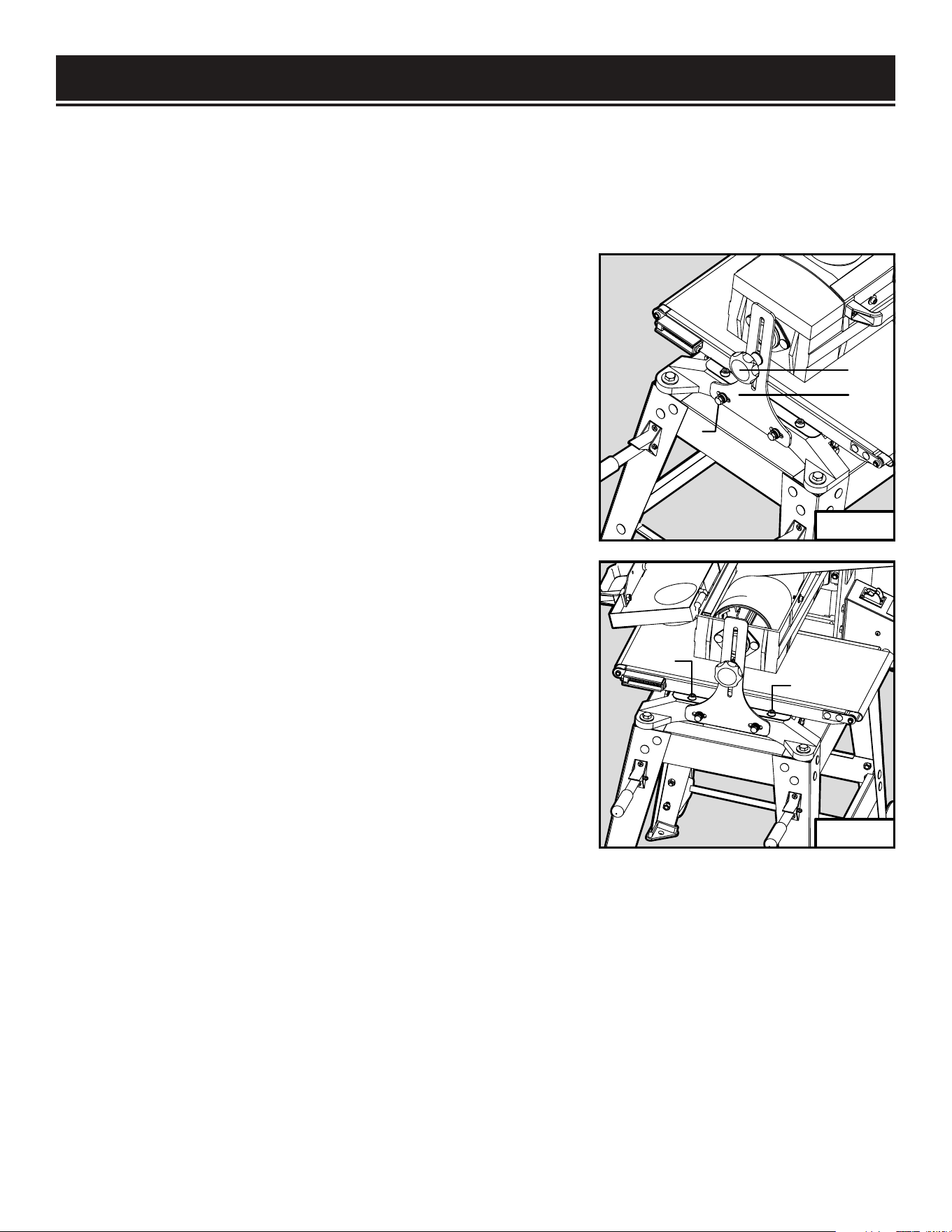
CONVEYOR FEED BELT REPLACEMENT (FIG. 25 & 26)
Regularly check the conveyor belt before operation. The conveyor belt may need replacement due to
normal wear and tear, contact with the sanding drum abrasive during operation, mis-tracking of the
conveyor belt, or excessive build-up. Follow the steps below to remove and replace the conveyor belt.
1. Turn off and disconnect the machine from the power source.
2. Release the conveyor belt tension by rotating the tensioning
screws on both sides of the conveyor in a counterclockwise
direction while holding the hex nuts in place.
3. Unscrew and remove the elevation lock knob (Fig. 25 - 1)
and flat washer from the side support frame (Fig. 25 - 2). Then
remove the hex bolts, spaces and washers (Fig. 25 - 3) from
the bottom of the side support frame. Keep all the removed
fasteners in the same configuration to be reinstalled later.
4. Remove the side support frame from the sander body.
5. Unscrew and remove the two cap screws and flat washers
(Fig. 26 - 1) from the conveyor table.
6. Hold the both sides of the conveyor belt and gently lift the
conveyor table as you slide off the conveyor belt.
7. Lift the conveyor table and slide on a new replacement belt.
Replace the conveyor table cap screw and flat washers.
8. Reinstall the side support frame and replace the fasteners to
secure the frame in place.
9. Center the new conveyor belt on the conveyor table and
evenly tension the belt.
1
2
3
1
1
Fig. 25
Fig. 26
27

PROBLEM COMMON CAUSE SOLUTION
Machine does
not start
1. Safety key removed from switch.
2. The power cord damaged or not
properly plugged in.
3. Faulty capacitor.
4. Motor overloaded and circuit breaker
trips.
5. Loose wire or connections.
1. Re-install switch safety key.
2. Check the power cord, power plug and the
power outlet. Do not use if power cord is damaged.
3. Test capacitor; replace if faulty.
4. Wait for motor to cool, then reduce depth of cut
or feed rate. Press breaker to reset.
5. Check power switch and circuit breaker box for
loose connections.
Machine stalls
or overloaded.
1. Workpiece material not suitable for
sanding
2. Depth of cut too much
3. Feed rate too high.
4. Power source not adequate.
5. Motor fan intake blocked.
1. Only sand natural wood products. Ensure
moisture content is below 20% (page 14).
2. Reduce depth of cut (page 18).
3. Reduce feed rate (page 19).
4. Ensure circuit amperage rating is adequate for
the tool.
5. Remove obstructions to fan intake.
Excessive
vibration or
noise.
1. Motor or components loose.
2. Machine sits unevenly on floor.
3. Motor fan rubbing on fan cover.
4. Faulty motor bearings.
5. Faulty sanding drum bearings.
6. Sandpaper damaged or not properly
installed.
1. Inspect and tighten/replace fasteners.
2. Bolt machine on stable stand, set on flat ground.
3. Fix/replace fan cover or fan.
4. Contact customer service at 1-800-232-1195 for
assistance.
5. Contact customer service at 1-800-232-1195 for
assistance.
6. Replace/re-install sandpaper.
Sandpaper
clogs quickly.
1. Depth of cut too much.
2. Feed rate too slow.
3. Sandpaper grit too fine.
4. Workpiece has high moisture content
or sap.
5. Poor dust collection.
6. Sandpaper loaded with sawdust and
gum.
1. Reduce depth of cut (page 18).
2. Increase feed rate (page 19).
3. Use coarser grit sandpaper.
4. Clean/replace sandpaper more frequently or use
different workpiece with less moisture.
5. Unclog ducts and re-connect dust collection
system.
6. Clean/replace sandpaper.
Burn marks on
workpiece.
1. Sanding grit too fine.
2. Sandpaper loaded with sawdust.
3. Depth of cut too much.
4. Feed rate too slow.
5. Sandpaper strip overlapped.
1. Use coarser grit sandpaper.
2. Clean/replace sandpaper.
3. Decrease depth of cut (page 18).
4. Increase feed rate (page 19).
5. Properly re-install sandpaper strip (page 16).
TROUBLESHOOTING
WARNING: Stop using the tool immediately if any of the following problems occur. Repairs
and replacements should only be performed by an authorized technician. For any questions,
please contact our customer service at (800) 232-1195, M-F 8-5 CST or email us at
28

ASSEMBLY & ADJUSTMENTS
TROUBLESHOOTING
PROBLEM COMMON CAUSE SOLUTION
Workpiece slips on
conveyor.
1. Conveyor belt dirty or worn.
2. Pressure rollers not properly
adjusted.
1. Clean/replace conveyor belt (page 22).
2. Properly adjust pressure roller (page 23).
Uneven
workpiece
thickness from
side to side.
1. Height lock knob not tight and
sanding drum is deflecting up.
2. Conveyor belt not parallel to
sanding drum.
3. Height adjustment tension screws
are too loose.
4. Conveyor belt is worn.
1. Fully tighten height lock knob after setting
the depth of cut.
2. Properly adjust conveyor belt to sanding drum
alignment (see page 23).
3. Properly adjust the height adjustment tension
screws (see page 22).
4. Replace conveyor belt (page 27).
Conveyor belt
slips or does
not track correctly
1. Belt tension not properly adjusted.
2. Belt tracking not properly
adjusted.
3. Conveyor belt is worn.
1. Properly adjust belt tension (page 18).
2. Properly adjust belt tracking (page 22).
3. Replace conveyor belt (page 27).
Height adjustment
wheel
hard to rotate.
1. Height lock knob too tight.
2. Leadscrew and nut clogged with
sawdust.
3. Height adjustment tension screws
are too tight.
1. Loosen the height lock knob.
2. Clean and lubricate the leadscrew and nut
(page 22).
3. Properly adjust the height adjustment tension
screws (page 22).
Sandpaper
strip becomes
loose or comes off
sanding drum.
1. Sandpaper strip not properly
wrapped onto drum.
2. Sandpaper strip not cut to the
correct
dimensions (3” x 62.5”).
3. Slack in sanding strip.
4. Torn or damaged sandpaper strip.
1. Re-install sandpaper strip properly (page 16).
2. Only use sandpaper strips that are cut to the
correct dimensions that match your existing
sandpaper.
3. Properly wrap sandpaper strip and make sure
the right end is fully inserted into the clamp slot
(page 16).
4. Replace sandpaper (page 16).
Ripples or
lines in workpiece.
1. Uneven feed rate.
2. Height lock knob not tight and
sanding drum deflecting from
workpiece.
1. Maintain an even feed rate through the entire
sanding operation.
2. Make sure the height lock knob is tight.
Snipe marks
in workpiece.
1. Improper pressure roller tension.
2. Workpiece too long without
sufficient support.
1. Adjust pressure roller tension evenly (page 23).
2. Use roller stands or tables on the infeed and
outfeed ends of the conveyor table to prevent
workpiece from bending.
29
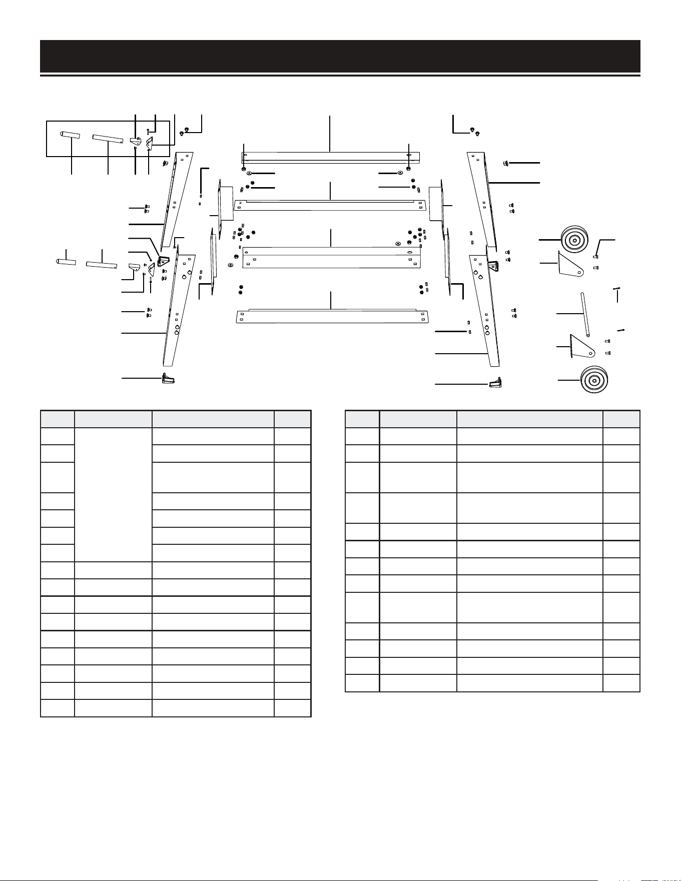
EXPLODED VIEW & PARTS LIST
1 2
34 5
6 7
19
19
8
11
6
9
1 2
7
3
4
6
19
10
9
13
12
14
28
27
17
15
16
15
28
27
17
19
29
12
17
24
9
19
18
20
21 22
23
25
26
21
STAND
30
NO. PART NO. DESCRIPTION QTY.
1
65911-001
(Handle)
Handle Grip 2
2 Handle 2
3
Phlp Hd Screw
M4-0.7 x 35
2
4 Handle Bracket 2
5 Handle Base 2
6 Flat Hd Scr M6-1 x 10 4
7 Hex Nut M4-0.7 2
8 65911-008 Left Front Stand Leg 1
9 65910-009 Leg Foot Pad 4
10 65911-010 Right Front Stand Leg 1
11 65910-011 Lock Nut M6-1 4
12 65910-012 Short Bottom Brace 2
13 65910-013 Front Short Top Brace 1
14 65910-014 Left Long Top Brace 1
15 65910-015 Long Bottom Brace 2
16 65910-016 Right Long Top Brace 1
NO. PART NO. DESCRIPTION QTY.
17 65910-017 Lock Nut M8-1.25 36
18 65911-018 Left Rear Stand Leg 1
19 65910-019
Carriage Bolt
M8-1.25 x 12
32
20 65910-020
Left Wheel
Mounting Bracket
1
21 65910-021 Wheel 5” 2
22 65910-022 Hex Bolt M8-1.25 x 16 4
23 65910-023 Wheel Axle 1
24 65911-024 Right Rear Stand Leg 1
25 65910-025
Right Wheel
Mounting Bracket
1
26 65910-026 Cotter Pin 4 x 20 2
27 65910-027 Flat Washer 10mm 4
28 65910-028 Lock Nut M10-1.5 4
29 65910-029 Rear Short Top Brace 1
NO. PART NO. DESCRIPTION QTY.
101 65910-101 Conveyor Belt 1
102 65910-102 Cap Screw M5-0.8 x 16 4
103 65910-103 Compression Spring 2
104 65910-104
Outfeed Adjustable Roller
Bracket
2
105 65910-105 Hex Nut M6-1 3
106 65910-106 Adjustable Slide 2
107 65910-107 Phlp Hd Scr M6-1 x 90 2
108 65910-108 Feed Roller Bushing 4
109 65910-109 Outfeed Roller 1
110 65910-110 Flat Washer 5mm 4
111 65910-111 Lock Washer 5mm 5
112 65910-112 Hex Nut M5-0.8 5
113 65910-113 Flat Washer 8mm 4
114 65910-114 Cap Screw M8-1.25 x 12 4
115 65910-115 Infeed Roller Bracket 1
116 65910-116 Carriage Bolt M6-1 x 16 6
117 65910-117 Flat Washer 6mm 12
118 65910-118 Lock Washer 6mm 9
119 65910-119 Infeed Roller 1
120 65910-120 Phlp Hd Scr M5-0.8 x 20 1
124 65910-121 Switch Cover 1
125 65910-122 Safety On / Off Switch 1
126 65910-123 Phlp Hd Scr M4-0.7 x 12 1
NO. PART NO. DESCRIPTION QTY.
131 65910-131 Switch Housing Bracket 1
132 65910-132 Terminal Block 4P 1
133 65910-133 Switch Housing Plate 1
134 65910-134
Transformer Omron
Hf-7A 24/120V
1
135 65910-135 Phlp Hd Scr M4-0.7 x 10 2
136 65910-136 Hex Bolt M8-1.25 x 16 4
137 65910-137 Insulation Plate 1
138 65910-138 Strain Relief 1/2” Snap-In 3
139 65910-139
Power Cord
14G 3C 10’ 42870
1
140 65910-140 Conveyor Motor 24Vdc 1
141 65910-141 Switch Housing 1
142 65910-142 Insulation Pad 1
143 65910-143 Hex Bolt M6-1 x 20 3
144 65910-144 Conveyor Clutch 2
145 65910-145 Flat Washer 4mm 2
146 65910-146 Flat Washer 5mm 2
147 65910-147
Vs Feed Dial
Hf-7A 71015
1
148 65910-148 Phlp Hd Scr M5-0.8 x 6 2
149 65910-149 Hex Nut M4-0.7 2
150 65910-150 Phlp Hd Scr M5-0.8 x 10 2
151 65910-151 Conveyor Table 1
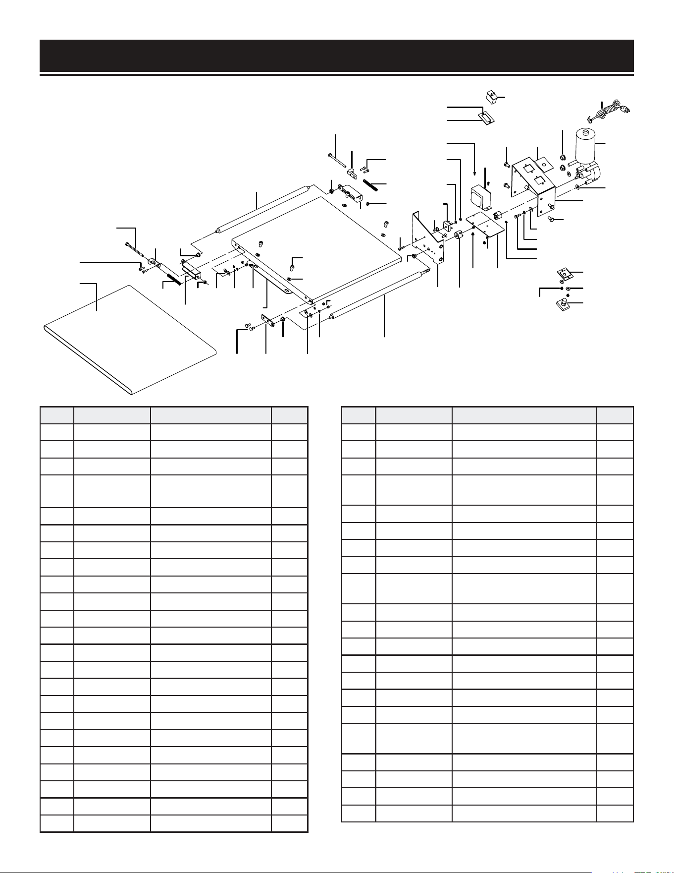
EXPLODED VIEW & PARTS LIST
101
102
107
106
103
104
105
108
111110 112
116 115
108
117
118
105
113
114
109
119
108
104
107
106
103
102
105
120
108
131
116
144
132
111
112
135
134
136 137
138
139
140
125
124
126
150
149
133
147
146
148
142
145
143
118
117
136
141
117
CONVEYOR
31
151
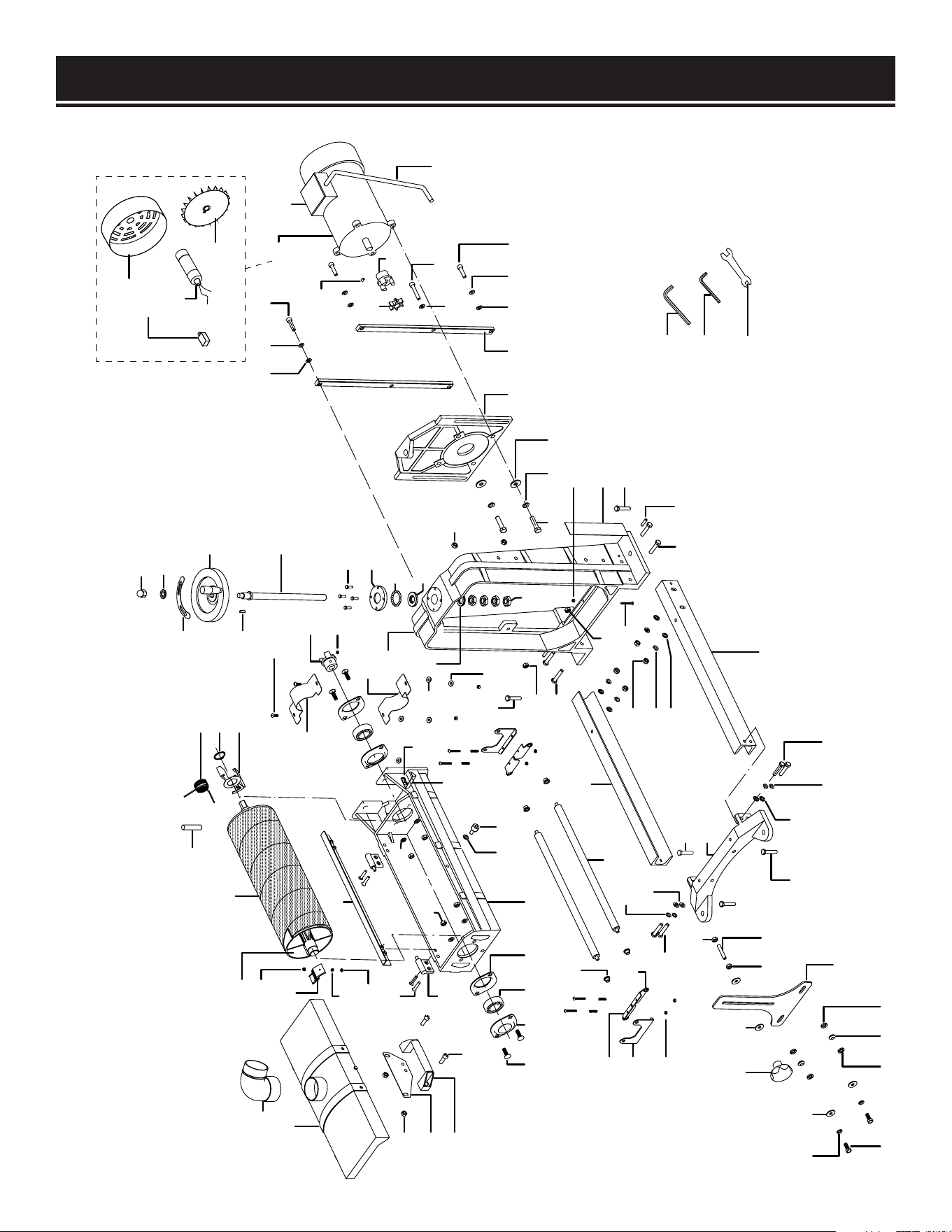
EXPLODED VIEW & PARTS LIST
202
268 226
274
273
286 287 286
272
205 271
227
289
226
268 269
267
270
289
266
227
268
273
262
205
263 264
289
265
228
275 276 277
283
284
285
278 279 226
226
268 280
282
235
236
281-5
281-3
281
281-1
281-2
281-6
281-4
226 268 280
227
261
263
205
289
288
240
260239
259
233
236
255
256
257
258
249
250
252
253
251
254
233
234
235
215
216
217
290
226
205
237
229
230232
224 225223222221
243
244
245
246
247
226
268
269
248
220
219
218
214
213
212
211
210
209
208
207
206
205
204
203
201
MAIN
32

No. Part No. Description Qty.
201 65910-201 Clutch Damper 1
202 65910-202 Hex Bolt M8-1.25 x 30 2
203 65910-203 Dust Hood 1
204 65910-204 Dust Connector 90 Deg 4” 1
205 65910-205 Lock Nut M8-1.25 9
206 65910-206 Locking Plate 1
207 65910-207 Dust Hood Handle 1
208 65910-208 Cap Screw M8-1.25 x 25 2
209 65910-209 Flat Hd Scr M4-0.7 x 8 1
210 65910-210 Left Sandpaper Clamp 1
211 65910-211 Lock Washer 4mm 1
212 65910-212 Hex Nut M4-0.7 1
213 65910-213 Sanding Drum V2.08.10 1
214 65910-SP80 Sandpaper 3”W x 63” 80 Grit 1
215 65910-215 Torsion Spring 1
216 65910-216 Ext Retaining Ring 28mm 1
217 65910-217 Right Sandpaper Clamp 1
218 65910-218 Internal Drum Guard 1
219 65910-219 Flat Hd Scr M6-1 x 30 4
220 65910-220 Dust Hood Hinge 2
221 65910-221 Carriage Bolt M8-1.25 x 25 4
222 65910-222 Outside Bearing Retainer 1
223 65910-223 Ball Bearing 6205-2Rs 2
224 65910-224 Internal Bearing Retainer 3
225 65910-225 Drum Housing 1
226 65910-226 Flat Washer 8mm 16
227 65910-227 Hex Nut M8-1.25 5
228 65910-228 Hex Nut M6-1 1
229 65910-229 Pointer 1
230 65910-230 Cap Screw M6-1 x 14 1
232 65910-232 Flat Washer 6mm 1
233 65910-233 Auxiliary Guard 2
234 65910-234 Phlp Hd Scr M5-0.8 x 16 4
235 65910-235 Drum Clutch 2
236 65910-236 Set Screw M6-1 x 8 2
237 65910-237 Cap Screw M4-0.7 x 20 2
238 65910-238 Flat Washer 4mm 2
239 65910-239 Flat Washer 5mm 2
240 65910-240 Lock Washer 5mm 2
241 65910-241 Phlp Hd Scr M4-0.7 x 30 4
242 65910-242 Compression Spring 4
243 65910-243 Pressure Roller Bracket 2
244 65910-244 Right Bracket Support 2
245 65910-245 Left Bracket Support 2
246 65910-246 Lock Nut M4-0.7 4
247 65910-247 Pressure Roller Bushing 4
248 65910-248 Pressure Roller 2
249 65910-249 Acorn Nut M12-1.75 1
No. Part No. Description Qty.
250 65910-250 Flat Washer 12mm 1
251 65910-251 Elevation Rotation Label 1
252 65910-252 Handwheel Assembly 1
253 65910-253 Elevation Leadscrew 1
254 65910-254 Key 5 x 5 x 16 4
255 65910-255 Hex Bolt M5-0.8 x 16 1
256 65910-256 Shaft End Cap 23
257 65910-257 Steel Ball 1
258 65910-258 Bearing Race 1
259 65910-259 Frame Casting 1
260 65910-260 Leadscrew Flat Washer 16mm 1
261 65910-261 Thin Nut M16-1.5 4
262 65910-262 Phlp Hd Scr M6-1 x 35 1
263 65910-263 Hex Bolt M8-1.25 x 40 4
264 65910-264 Roll Pin 6 x 26 2
265 65910-265 Elevation Scale 1
266 65910-266 Outfeed Roller Support 1
267 65910-267 Infeed Roller Support 1
268 65910-268 Lock Washer 8mm 12
269 65910-269 Hex Bolt M8-1.25 x 25 4
270 65910-270 Conveyor Support 1
271 65910-271 Threaded Stud M8-1.25 x 80 1
272 65910-272 Drum Housing Support 1
273 65910-273 Fender Washer 8mm 6
274 65910-274 Knob M8-1.25 1
275 65910-275 Hex Bolt M10-1.5 x 30 4
276 65910-276 Lock Washer 10mm 4
277 65910-277 Flat Washer 10mm 4
278 65910-278 Motor Mount 1
279 65910-279 Gib 2
280 65910-280 Cap Screw M8-1.25 x 30 4
281 65910-281 Motor 1-1/2Hp 110V 60Hz 1
281-1 65910-281.1 Motor Fan Cover 1
281-2 65910-281.2 Motor Fan 1
281-3 65910-281.3 Motor Junction Box 1
281-4 65910-281.4 S Capacitor 80 uF 300V 1
281-5 65910-281.5 Motor Cord 14G 3C 18” 1
281-6 65910-281.6 Circuit Breaker 12A 1
282 65910-282 Cap Screw M8-1.25 x 45 2
283 65910-283 Hex Wrench 6mm 1
284 65910-284 Hex Wrench 5mm 1
285 65910-285 Combo Wrench 11mm/13mm 1
286 65910-286 Flat Washer 8mm 4
287 65910-287 Spacer 8mm 4
288 65910-288 Hex Nut M5-0.8 4
289 65910-289 Hex Bolt M10-1.5 x 35 4
290 65910-290 Holding Pin 1
33

WARRANTY STATEMENT
WEN Products is committed to building tools that are dependable for years. Our warranties are consistent with this
commitment and our dedication to qualit
y.
LIMITED WARRANTY OF WEN PRODUCTS FOR HOME USE
GREA
T LAKES TECHNOLOGIES, LLC (“Seller”) warrants to the original purchaser only, that all WEN consumer
power
tools
will be free from defects in material or workmanship during personal use for a period of two (2) years from
date
of
purchase or 500 hours of use; whichever comes first. Ninety days for all WEN products if the tool is used for pro
-
fessional or commer
cial use. Purchaser has 30 days from the date of pur
chase to report missing or damaged parts.
SELLER’S SOLE OBLIGA
TION AND YOUR EXCLUSIVE REMEDY under this Limited Warranty and, to the extent per
-
mitted
by law, any warranty or condition implied by law, shall be the replacement of parts, without charge, which
are
defective
in material or workmanship and which have not been subjected to misuse, alteration, careless
handling,
misrepai
r, abuse, neglect, normal wear and tear, improper maintenance, improper storage, incorrect
lubricants/
fuels,
or other conditions adversely affecting the Product or the component of the Product, whether by accident
or
intentionall
y, by persons other than Seller. To make a claim under this Limited Warranty, you must make sure to
keep
a
copy of your proof of purchase that clearly defines the Date of Purchase (month and year) and the Place of Pur
-
chase. Place of Pur
chase must be a direct vendor of Great Lakes Technologies, LLC. Pur
chasing through third party
vendors,
including but not limited to garage sales, pawn shops, resale shops, or any other secondhand mer
chant,
voids the warranty included with this product. Contact [email protected] or 1-800-232-1195 with the
following
information to make arrangements: your shipping address, phone number, serial number, required
part
numbers, and proof of purchase. Damaged or defective parts and products may need to be sent to WEN before the
replacements can be shipped out.
Upon
the confirmation of a WEN representative, your product may qualify for repairs and service work. When re
-
turning
a product for warranty service, the shipping charges must be prepaid by the purchaser. The product
must
be
shipped in its original container (or an equivalent), properly packed to withstand the hazards of shipment.
The
product
must be fully insured with a copy of the proof of purchase enclosed. There must also be a description of
the
problem
in order to help our repairs department diagnose and fix the issue. Repairs will be made and the
product
will be returned and shipped back to the purchaser at no charge for addresses within the contiguous United States.
THIS
LIMITED WARRANTY DOES NOT APPLY TO ITEMS THAT WEAR OUT FROM REGULAR USAGE OVER
TIME,
INCLUDING
FILTERS, SPARK PLUGS, VOLTAGE REGULATORS, BRUSHES, GASKETS, O-RINGS, WHEEL KITS, BA
T-
TERIES,
RECOIL STARTERS, HIGH PRESSURE HOSES, SPRAY GUNS, ETC. ANY IMPLIED WARRANTIES
SHALL
BE
LIMITED IN DURATION TO TWO (2) YEARS FROM DATE OF PURCHASE. SOME STATES IN THE U.S. AND
SOME
CANADIAN
PROVINCES DO NOT ALLOW LIMITATIONS ON HOW LONG AN IMPLIED WARRANTY LASTS, SO
THE
ABOVE LIMI
TATION MAY NOT APPLY TO YOU.
IN
NO EVENT SHALL SELLER BE LIABLE FOR ANY INCIDENTAL OR CONSEQUENTIAL DAMAGES (INCLUDING
BUT
NOT
LIMITED TO LIABILITY FOR LOSS OF PROFITS) ARISING FROM THE SALE OR USE OF THIS PRODUCT.
SOME
ST
ATES IN THE U.S. AND SOME CANADIAN PROVINCES DO NOT ALLOW THE EXCLUSION OR LIMITATION OF IN
-
CIDENT
AL OR CONSEQUENTIAL DAMAGES, SO THE ABOVE LIMITATION OR EXCLUSION MAY NOT APPLY TO
YOU.
THIS
LIMITED WARRANTY GIVES YOU SPECIFIC LEGAL RIGHTS, AND YOU MAY ALSO HAVE OTHER
RIGHTS
WHICH
VARY FROM STATE TO STATE IN THE U.S., PROVINCE TO PROVINCE IN CANADA AND FROM COUNT
RY
TO COUNT
RY.
THIS
LIMITED WARRANTY APPLIES ONLY TO ITEMS SOLD WITHIN THE UNITED STATES OF AMERICA,
CANADA
AND
THE COMMONWEALTH OF PUERTO RICO. FOR WARRANTY COVERAGE WITHIN OTHER COUNTRIES, CON
-
T
ACT THE WEN CUSTOMER SUPPORT LINE. FOR WARRANTY PARTS OR PRODUCTS REPAIRED UNDER WA
R-
RANTY
SHIPPING TO ADDRESSES OUTSIDE OF THE CONTIGUOUS UNITED STATES, ADDITIONAL
SHIPPING
CHARGES MAY APPLY.
34

35
NOTES

THANKS FOR
REMEMBERING