Table of Contents
3
EN
1Installation 12
1.1 Product dimensions 12
1.2 Unpacking, moving and positioning the range 15
1.3 Electrical connection 17
1.4 Gas connection 18
1.5 Conversion to propane gas (LPG) 21
1.6 Wall and floor attachment 29
1.7 For the installer 32
IMPORTANT SAFETY INSTRUCTIONS
WARNING
If the instructions contained in this manual are not followed
precisely, a fire or explosion may result causing property
damage, personal injury or loss of life.
Do not store or use gasoline or other flammable vapors, liquids
or materials near this or any other appliance.
- WHAT TO DO IF YOU SMELL GAS
• Do not try to light any appliance.
• Do not touch any electrical switch.
• Do not use any telephones in your building.
• Immediately call your gas supplier from a neighbor's phone.
Follow the gas supplier's instructions.
• If you cannot reach your gas supplier, call the fire
department.
- Installation and service must be performed by a qualified
installer, service company or gas supplier.
INSTALLATION AND SERVICE MUST BE PERFORMED BY A
QUALIFIED INSTALLER.
IMPORTANT: SAVE FOR THE LOCAL INSPECTOR’S USE.
Important Safety Instructions
4
Important Notes to the Installer
• Read all instructions contained in
these installation instructions
before installing the range.
• Remove all packing material from
the oven and the drawer
compartments before connecting
the electrical and gas supplies to
the range.
• Observe all governing codes and
ordinances. Be sure to leave
these instructions with the
consumer.
Important Note to the Customer
• Keep these instructions with your
owner's guide for future
reference.
Definitions
• This manual contains important
safety symbols and instructions.
Please pay attention to these
symbols and follow all instructions
given.
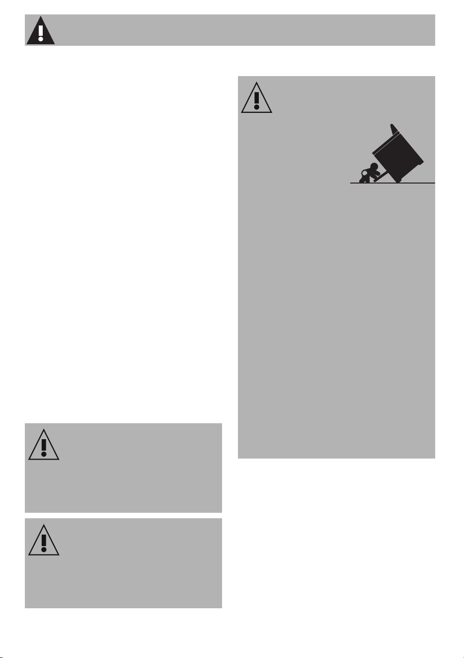
TIP OVER HAZARD
WARNING
This symbol will help alert you to
situations that may cause serious bodily
harm, death or property damage.
CAUTION
This symbol will help alert you to
situations that may cause injury or
property damage.
WARNING: Tip Over Hazard
• A child or adult
could tip the
range over and
be killed.
• Install the anti-tip
device on the floor or wall as
per the installation instructions.
• Engage the range with the anti-
tip device as per the installation
instructions.
• Ensure the anti-tip device is re-
engaged when the range is
moved.
• Do not operate the range
without the anti-tip device in
place and engaged.
• See installation instructions for
details.
• Failure to follow these
instructions can result in death or
serious burns to children and
adults.

Important Safety Instructions
5
EN
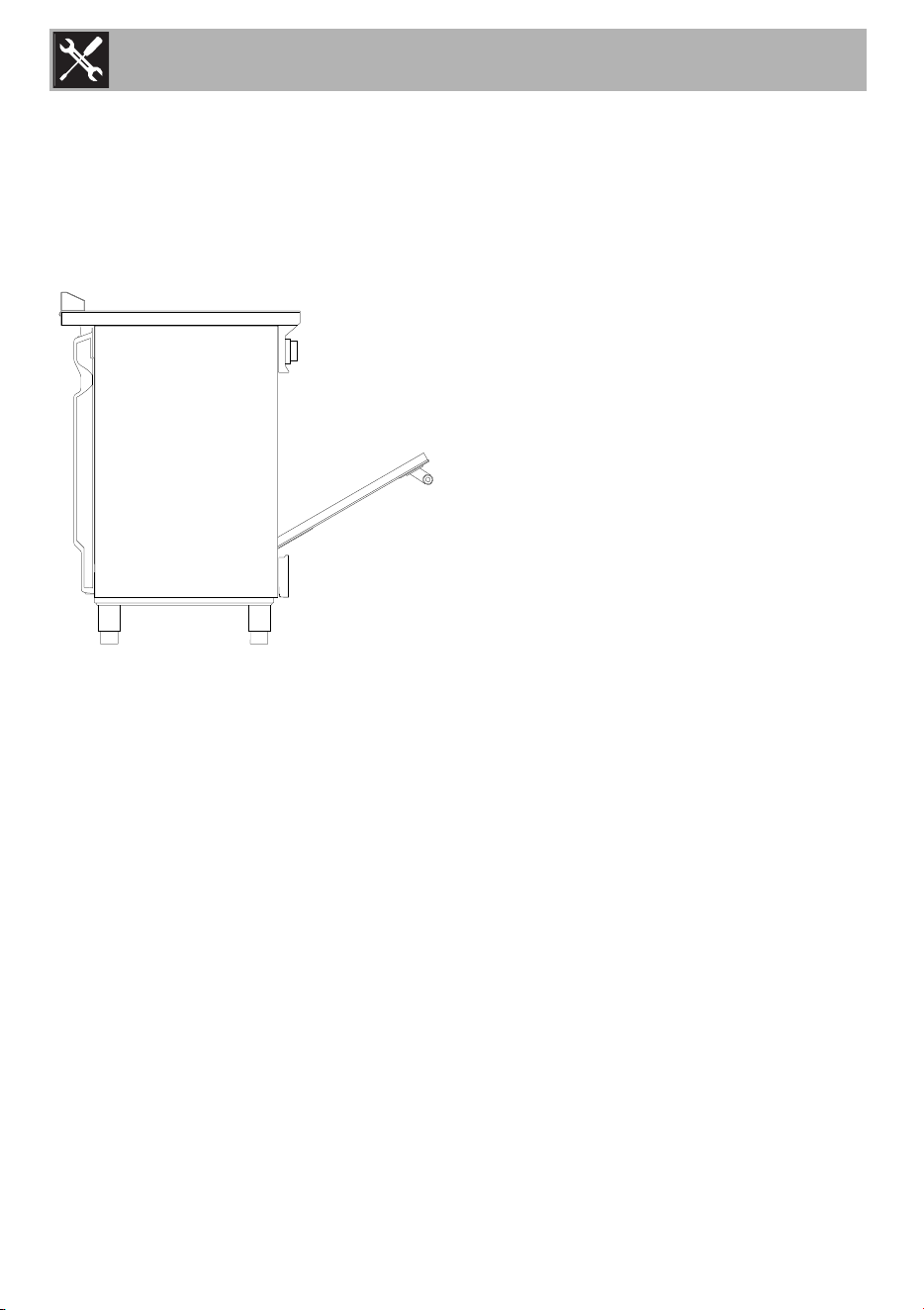
• Check for proper installation and
use of the anti-tip bracket.
Carefully tip the range forward
by pulling it from the back to
ensure that the anti-tip bracket
engages the range leg and
prevents tip-over. The range
should not move more than 1”
(2.5cm).
Appliance Handling Safety
Hidden surfaces may have sharp
edges. Use caution when reaching
behind or under the appliance.
• Wear gloves to avoid cutting
fingers on sharp edges during
installation.
• The unit is heavy and requires at
least two persons or proper
equipment to move it.
• Do not lift appliance by the oven
door handle. Remove the oven
door for easier handling and
installation.
• Do not use the oven for storage.
Safety Codes and Standards
This appliance complies with one or
more of the following Standards:
ANSI Z21.1/CSA 1.1 Household
Cooking Gas Appliances
• It is the responsibility of the owner
and the installer to determine
whether additional requirements
and/or standards apply to
specific installations.
• Installation must conform with
local codes or, in the absence of
local codes, with the National
Fuel Gas Code, ANSI Z223.1/
NFPA 54 or, in Canada, the
Natural Gas and Propane
Installation Code, CSA B149.1.
To check if the anti-tip
bracket is installed
properly, use both arms
and grasp the back edge
of the range. Carefully
attempt to tilt the range forward. When
properly installed, the range should not
tilt forward.
Refer to the anti-tip bracket installation
instructions supplied with your range for
proper installation.
Important Safety Instructions
6
• The appliance must be electrically
grounded in accordance with
local codes or, in the absence of
local codes, with the National
Electrical Code, NFPA 70 latest
edition or, in Canada, the
Canadian Electric Code, CSA
C22.1-02.
• Before installing the range in an
area covered with linoleum or
any other synthetic floor covering,
make sure the floor covering can
withstand heat at least 90°F
above room temperature without
shrinking, warping or discoloring.
Do not install the range over
carpeting unless you place an
insulating pad or sheet of ¼"
(10,16cm) thick plywood
between the range and
carpeting.
• Be sure your range is installed
and grounded properly by a
qualified installer or service
technician.
• Make sure the wall coverings
around the range can withstand
the heat generated by the range.
• Do not store items of interest to
children in the cabinets above the
range. Children could be
seriously burned if they climb on
the range to reach items.
• To eliminate the need to reach
over the surface burners, cabinet
storage space above the burners
should be avoided.
• Do not use the oven as a storage
space. This creates a potentially
hazardous situation.
WARNING
Never leave children alone or
unattended in the area where an
appliance is in use. As children grow,
teach them the proper, safe use of all
appliances. Never leave the oven door
open when the range is unattended.
CAUTION
Stepping, leaning or sitting on the doors
or drawers of this range can result in
serious injuries and can also cause
damage to the range.
Important Safety Instructions
7
EN
• Do not store or use gasoline or
other flammable vapors and
liquids near this or any other
appliance. Explosions or fires
could result.
• Adjust the size of the surface
burner flame so it does not extend
beyond the edge of the cooking
utensil. An excessive flame is
hazardous.
• Never use your range for
warming or heating the room.
Prolonged use of the range
without adequate ventilation can
be dangerous.
• In the event of an electrical power
outage, the surface burners can
be lit manually. To light a surface
burner, hold a lit match to the
burner head and slowly turn the
Surface Control knob to LITE. Use
caution when lighting surface
burners manually.
• Unlike the standard gas range,
THIS COOKTOP IS NOT
REMOVABLE. Do not attempt to
remove the cooktop.
Electric Safety
• Personal injury or death from
electrical shock may occur if the
appliance is not installed by a
qualified installer or electrician.
• Make sure your appliance is
properly installed and grounded
by a qualified electrician.
Installation, electrical connections
and grounding must comply with
all applicable codes.
WARNING
Do not repair, replace or remove any
part of the appliance unless specifically
recommended in the manuals. Improper
installation, service or maintenance can
cause injury or property damage. Refer
to this manual for guidance. All other
servicing should be done by an
authorized service provider.
WARNING
Before you plug the electrical cord into
an outlet, make sure that all the
appliance controls are in the OFF
position.

Important Safety Instructions
8
• Before installing, turn power OFF
at the service panel. Lock service
panel to prevent power from
being turned ON accidentally.
• For appliances equipped with a
cord and plug, do not cut or
remove the ground prong. It must
be plugged into a matching
grounding type receptacle to
avoid electrical shock. If there is
any doubt as to whether the wall
receptacle is properly grounded,
the customer should have it
checked by a qualified
electrician.
• Do not use an extension cord.
• Do not use an adapter.
• If required by the National
Electrical Code (or Canadian
Electrical Code), this appliance
must be installed on a separate
branch circuit.
• The circuit breaker should have a
contact separation of at least 3 mm
on all poles.
• INSTALLER – show the owner the
location of the circuit breaker or
fuse. Mark it for easy reference.
• Refer to rating label for more
information.
Gas safety
• Install a gas shutoff valve near the
appliance. It must be easily
accessible in an emergency.
• Leak testing must be conducted
by the installer according to the
instructions in this manual.
• The appliance and its individual
shutoff valve must be
disconnected from the gas supply
piping system during any pressure
testing at pressures in excess of ½
psi (3.5 kPa).
• The appliance must be isolated
from the gas supply piping system
by turning off its individual manual
shutoff valve during pressure
testing of the gas supply piping
system at test pressures equal to
or less than ½ psi (3.5.5kPa).
WARNING
Burning gas cooking fuel generates some
by-products which are on the list of
substances which are known by the State
of California to cause cancer or
reproductive harm. To minimize exposure
to these substances, always operate this
unit according to the instructions
contained in this booklet and provide
good ventilation.
Important Safety Instructions
9
EN
• The minimum supply pressure must
be 1" water column above the
manifold pressure printed on the
rating label. The maximum supply
pressure of 14.0 inches water
column (34.9 Millibars) must not
exceed.
• IMPORTANT SAFETY NOTICE
Burning gas cooking fuel
generates some by products
which are on the list of substances
which are known by the State of
California to cause cancer or
reproductive harm. To minimize
exposure to these substances,
always operate this unit
according to the instructions
contained in this booklet and
provide good ventilation.
Proposition 65 Warning:
This product may contain a chemical known
to the State of California, which can cause
cancer or reproductive harm. Therefore, the
packaging of your product may bear the
following label as required by California:
Propane Gas Installation
• The propane gas tank must be
equipped with its own high
pressure regulator. In addition,
the regulator supplied with this
unit must also be used.
• The appliance is shipped from the
factory for use with natural gas. It
must be converted for use with
propane. The conversion must be
done by a qualified technician or
installer.
• This appliance can operate up to
an altitude of 10,000 ft. (3048 m.)
elevation above sea level. For use
with propane gas, the appliance
must be converted in accordance
with the propane conversion
instructions.
For installations in Massachusetts
• Installation must be performed by
a qualified or licensed contractor,
plumber or gas fitter qualified or
licensed by the state, province or
region where this appliance is
being installed.
• Shut-off valve must be a “T”
handle gas cock.
• Flexible gas connector must not
be longer than 36 inches.
• Installer - show the owner where
the gas shut-off valve is located.
State of California Proposition 65
WARNING
Cancer or Reproductive Harm -
www.P65Warnings.ca.gov

Important Safety Instructions
10
Related Equipment Safety
• The appliance should only be
used if installed by a qualified
technician in accordance with
these installation instructions and
all applicable regulations and
codes. The manufacturer is not
responsible for damages resulting
from incorrect installation.
• Remove all tape and packaging
before using the appliance.
Dispose of the packaging after
unpacking the appliance. Never
allow children to play with
packaging material.
• Never modify or alter the
construction of the appliance. For
example, do not remove leveling
legs, panels, wire covers or anti-
tip brackets/screws.
• To eliminate the risk of burns or fire
by reaching over hot surface
units, cabinet storage space
located above the surface units
should be avoided. If cabinet
storage is to be provided, the risk
can be reduced by installing a
hood that projects horizontally a
minimum of 5 inches (127 mm)
beyond the bottom of the cabinet.
Be sure cabinets above the
cooktop are a maximum of 13"
(330 mm) deep.
• When installing a cooktop over a
single oven, be sure to follow
both the oven and cooktop
installation manuals.
Ventilation Recommendations
• Do not obstruct air vents or heat
vent openings.
• We strongly recommend the
installation of a ventilation hood
above this appliance. The hood
must be installed according to the
instructions provided with the
hood.
• Do not obstruct the flow of
combustion air at the oven vent
nor around the base or beneath
the lower front panel of the range.
Avoid touching the vent openings
or nearby surfaces as they may
become hot while the oven is in
operation. This range requires
fresh air for proper burner
combustion.
• Air curtains or other overhead
range hoods, which operate by
blowing air downwards onto a
range, shall not be used in
conjunction with gas ranges other
than when the hood and range
have been designed, tested and
listed by an independent test
laboratory for use in combination
with each other.
Important Safety Instructions
11
EN
High altitude installation
• This appliance can operate up to
an altitude of 10,000 ft.
(3048 m.) elevation above sea
level. If desired, for altitudes
above 2,000 ft (610 m) elevation
above sea level, adjustments may
be made.
• Burners should be checked at the
lowest setting, if the flame is not
stable, the simmer should be
increased until the flame is stable.
This can be done by adjusting the
bypass screw in the valve. If flame
performance is satisfactory,
adjustment will not be required.
• It is required that a Certified
Professional make the high
altitude adjustments during
installation.
• Improper installation is not
covered by the warranty.
How to read the user manual
This user manual uses the following reading
conventions:
1. Use instruction sequence.
• Single use instructions.
SAVE THESE INSTRUCTIONS
CAUTION
The appliance should not be installed
with a ventilation system that blows air
downward toward the burners. This type
of ventilation system may cause ignition
and combustion problems with the gas
cooking appliance and may result in
personal injury or unintended operation.
WARNING
If the information in this manual is not
followed exactly, fire or shock may result
causing property damage or personal
injury.
Installation
Information for the qualified
technician: installation, operation
and inspection.
Safety instructions
Information
Advice
Installation
12
1 Installation
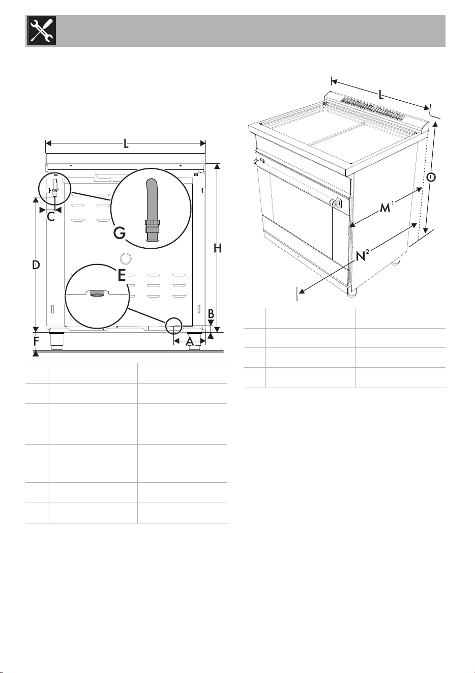
1.1 Product dimensions
Overall dimensions: Location of gas and
electrical connection points.
E = Electrical connection
G = Gas connection
1
Measurement M varies according to the
model: the minimum is obtained without the
rear spacers (see "Island installation") and
the maximum is obtained for traditional
installation (slot-in installation - with the rear
spacers).
2
Measurement N refers to the open door.
A
5
1
/
4
"
134,4 mm
B
1
3
/
16
"
30 mm
C
1
11
/
16
"
42,6 mm
D
25
1
/
4
"
641,3 mm
F
min. 3
5
/
16
"
Max. 4
3
/
4
"
min. 84 mm
Max. 120 mm
H
31
7
/
16
"
800 mm
L
29
15
/
16
"
760 mm
L
29
15
/
16
"
760 mm
M
1
25” 630 mm
N
2
45
3
/
8
"
1153 mm
O
33
9
/
16
"
851 mm
Installation
13
EN
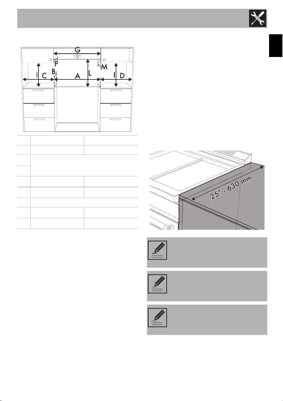
Cabinet clearances
Option 1
C ≥ 12” - 305 mm - D ≥ 28” - 711 mm
Option 2
D ≥ 28” - 711 mm - C ≥ 12” - 305 mm
Clearance L can have the following values:
• L = 30” - 762 mm min. when the bottom
of wood or metal cabinet is protected by
not less than ¼” (0.64 cm) flame
retardant millboard covered with not less
than No. 28 MSG sheet steel, 0.015"
(0.4 mm) stainless steel, 0.024" (0.6 mm)
aluminum or 0.020" (0.5 mm) copper.
• L = 36" - 914 mm min. clearance
between the top of the cooking surface
and the bottom of an unprotected wood
or metal cabinet.
1
min. clearance from the sides of range to
side wall or other combustible material;
2
min. cabinet opening width;
3
upper cabinet to countertop;
4
max. upper cabinet depth.
The side cabinet depth (clearance B) must
match the front edge of the range side
panel.
A 30" 762 mm
B 25” 630 mm
C
1
see notes below
D
1
G
2
30" 762 mm
I
3
18" 457 mm
L see notes below
M
4
13" 330 mm
P
4
13" 330 mm
The distance between the
appliance and the rear wall below
the worktop is zero.
The distance between the
appliance and the side cabinets
below the worktop is zero.
Any opening in the wall behind the
appliance and in the floor under
the appliance shall be sealed.
Installation
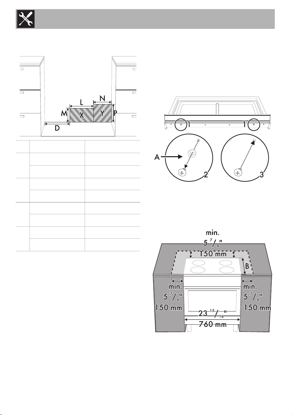
14
Location of the gas and electric
outlets
X = Grounded outlet
Y = Gas supply line
Island installation
If the appliance is installed as an island:
1. Unscrew the screws shown.
2. Remove the spacers (A).
3. Replace the screws that were previously
removed.
Keep a minimum clearance of 5
7
/
8
"
(150 mm) between the appliance and the
other furnishings or decorative elements
according to the diagram below.
D
min. 5
7
/
8
“
min. 150 mm
L
min. 5
13
/
16
“
min. 148 mm
Max. 12
3
/
16
“
Max. 310 mm
M
min. 2” min. 51 mm
Max. 4
3
/
4
”
Max. 120 mm
N
min. 2” min. 51 mm
Max. 7
7
/
8
”
Max. 200 mm
P
min. 2” min. 51 mm
Max. 10
7
/
8
”
Max. 275 mm
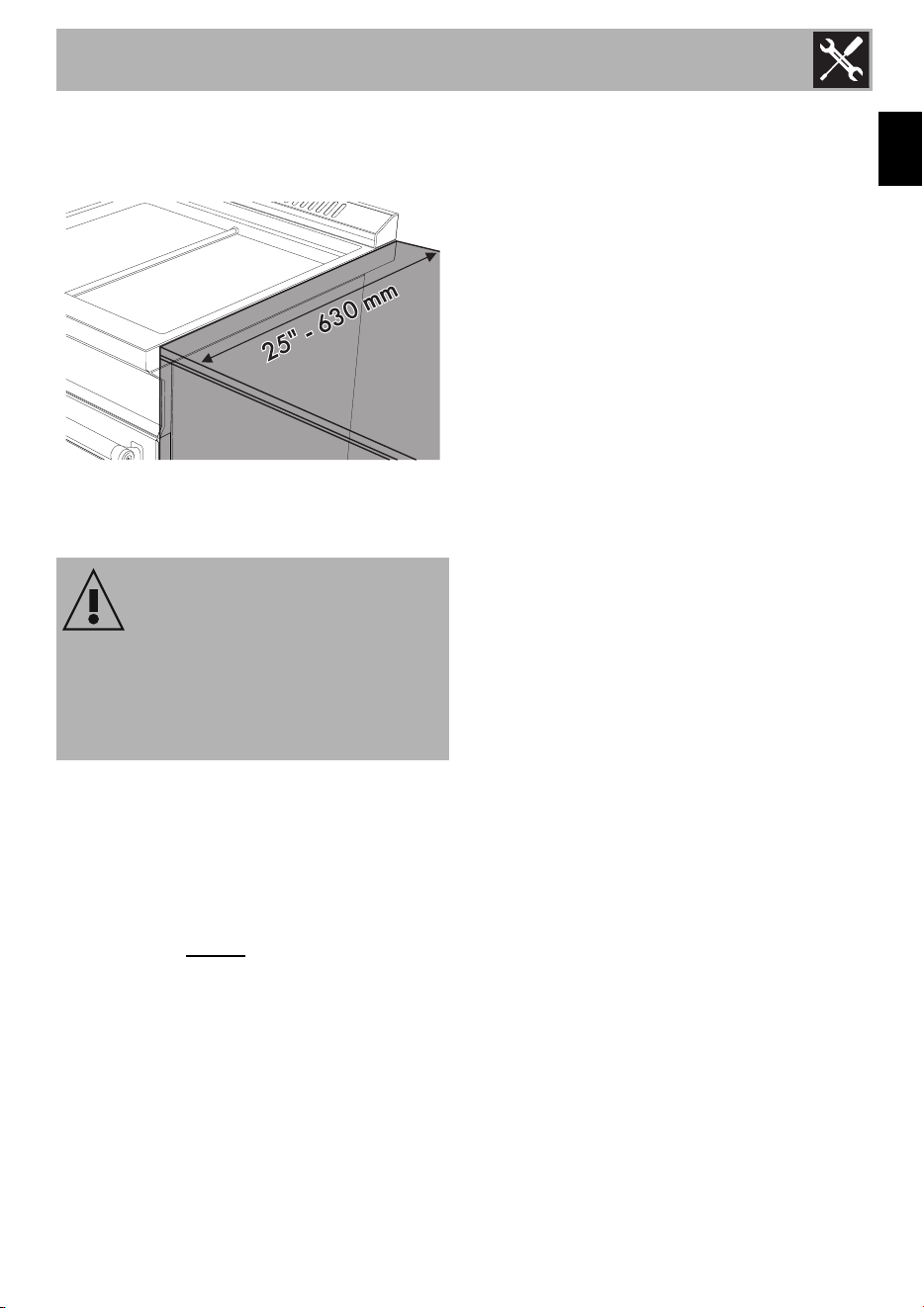
Installation
15
EN
The side cabinet depth (clearance B) must
match the front edge of the range side
panel.
1.2 Unpacking, moving and
positioning the range
• It is recommended that the grates, the
griddle plate and burner heads, burner
caps, front kick panel and oven racks be
removed to facilitate handling. This will
reduce the weight for moving.
• When positioning the appliance during
installation, do not
use the door handle
to lift or move this appliance.
• Remove the outer carton and packing
material from the shipping base.
• Remove angle-mounting brackets from
the range.
• Due to its weight, a dolly/fork lift with
soft rubber tread wheels should be used
to move this unit. The weight must be
supported uniformly across the bottom.
• The floor under the legs should be
protected (wood, strips, carpet,
paneling, etc.) before pushing the unit
into position.
• The anti-tip device must be installed, and
the gas and electrical connections
should be made before the range is
placed in its final position.
• Ensure that the burner caps are correctly
positioned on the burner bases on the
cooktop.
• Legs should be installed near to where
the appliance will be used as they are
not secure for long transit. Keep the unit
raised so that the legs can be screwed
into their couplings, then lower the range
gently to prevent the legs and mounting
hardware from being subject to any
undue strain. Instead of tilting the unit, it is
recommended that a pallet or lift jack be
used.
• After making the gas and electrical
connections, screw on the four feet
supplied with the appliance.
CAUTION
This unit is designed as a cooking
appliance. For safety reasons, never use
it for warming the room or as a space
heater.
Installation
16
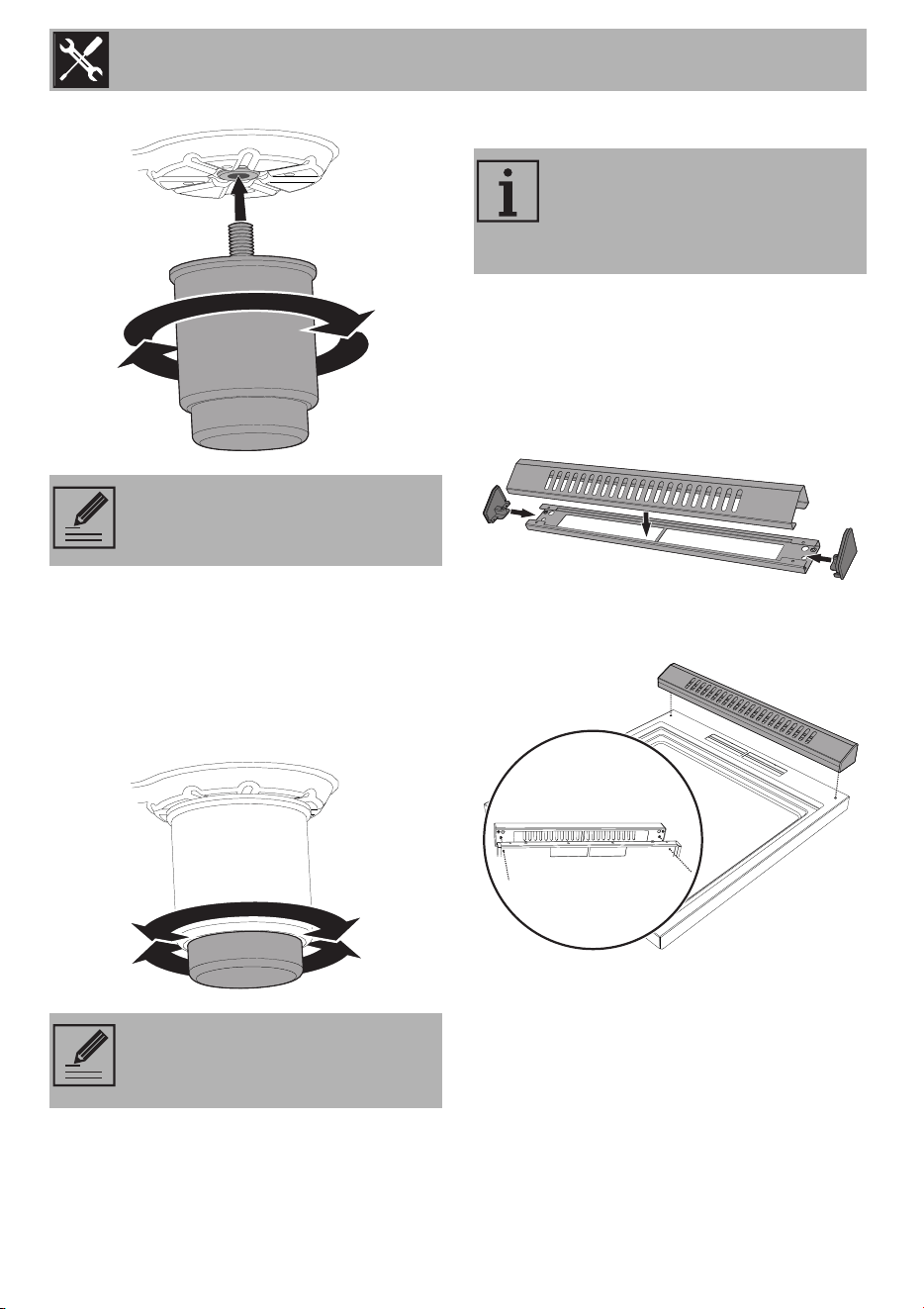
The appliance must sit level on the floor to
ensure stability:
• Screw or unscrew the bottom part of the
foot until the appliance is stable and
level on the floor. The adjustment range
of the screw is 1
1
/
4
“ (32 mm).
Assembling the backguard
The backguard must always be positioned
and secured correctly on the appliance.
1. Assembling the backguard. You can find
the assembly instructions for the
backguard in the instructions sheet
provided.
2. Position the backguard above the top,
taking care to align the holes.
3. Secure the backguard to the top by
tightening screws.
4. Once you have fixed the backguard to
the appliance, you must insert the screws
NOTE: First insert the front feet and
then the rear ones.
NOTE: this appliance must only
use the specific leveling legs
provided by the manufacturer.
The backguard provided is an
integral part of the product; it must
be fastened to the appliance prior
to installation.
Installation
17
EN
and spacers provided that are necessary
for the slot-in installation.
1.3 Electrical connection
This range is equipped with a factory-
connected power cord. The cord must be
connected to a grounded 120 volt outlet. If
no outlet is available, have one installed by
a qualified electrician.
See the rating plate for technical
specifications. The rating plate is visibly
located on the right side of the oven door
frame.
WARNING
Electrical shock hazard
•This appliance is
equipped with a three-
prong grounding plug for
your protection against
electric shock and should
be plugged directly into a properly
grounded receptacle. Do not cut or
remove the grounding prong from this
plug.
• The grounding prong must be plugged
into a matching grounding type
receptacle and connected to a correctly
polarized 120-Volt circuit. If there is any
doubt as to whether the wall receptacle
is properly grounded, have it checked
by a qualified electrician.
• Failure to do any of the above could
result in a fire, personal injury or
electrical shock.
WARNING
Electrical shock hazard
• Disconnect the electrical supply before
servicing the appliance
• It is the personal responsibility of the
consumer to have the appropriate outlet
or junction box with the correct, properly
grounded wall receptacle installed by a
qualified electrician. It is the
responsibility and obligation of the
consumer to contact a qualified installer
to ensure that the electrical installation is
suitable and in conformance with all
local codes and ordinances.
CAUTION
Do not use multiple outlets, extension
cords or adapters.
Installation
18
These ID plates must never be removed.
1.4 Gas connection
The appliance is shipped from the factory
for use with natural gas at a pressure of 5"
of water column. When checking if the
regulator is working properly, the inlet
pressure must be at least 1" greater than the
operating (manifold) pressure above.
When used with natural gas, the pressure
supplied to the regulator must be between
6" and 10.5" of the water column.
WARNING: Explosion hazard
• Use a new AGA or CSA-certified
connector.
• Install a manual shut-off valve.
• Securely tighten all gas connections.
• If connected to propane, have a
qualified technician ensure that the gas
pressure does not exceed a 14" W.C.P.
• Examples of qualified technicians include
licensed heating personnel, authorized
gas company personnel, and authorized
service personnel.
• Failure to do so can result in loss of life,
explosion, or fire.
NOTE:
• Observe all codes and
ordinances in force.
• The range must be connected to
a standard gas supply.
Installation
19
EN
To convert the appliance to propane gas
see "Conversion to propane gas (LPG)".
The conversion must be done by a qualified
technician or installer. Use a flexible gas
pipe with a length of at least 5 ft (1.5 m).
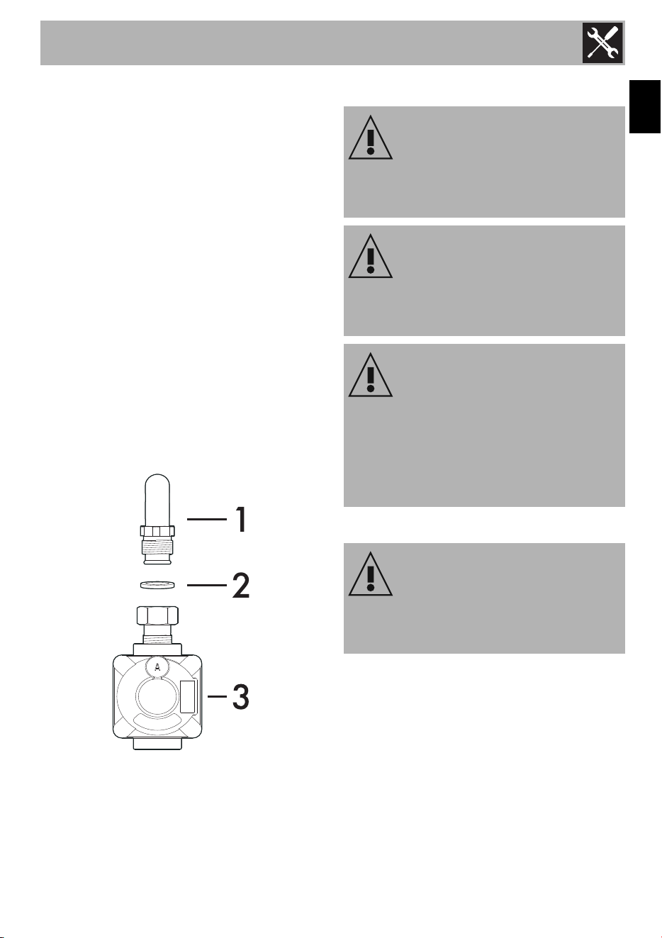
The gas inlet to the unit is located at the
back right of the appliance. Install the
pressure regulator (supplied with the unit)
on the gas inlet. Install the gasket (supplied
with the unit) between the inlet and the
regulator. Position the regulator so that the
cap D is easily accessible. Tighten the nut
on the gas inlet so that it is hand tight plus
1/3 turn. Connect the gas pipe to the
regulator using Teflon tape or pipe-joint
compound (resistant to propane gas and
natural gas). Turn so that it is hand tight plus
1/3 turn. Do not exceed 1 turn for
alignment, to prevent possible damage to
the gas pressure regulator.
1 Gas inlet (attached to the appliance).
2 Gasket.
3 Pressure regulator.
Testing for gas leaks
Gas leak tests should be performed before
the testing the electric ignition of the burners:
1. Turn on gas supply.
2. Apply a non-corrosive leak detection
fluid (e.g. soapy water) to all joints and
conduits.
3. If bubbles appear, it means there is a
leak. Turn off the gas supply and tighten
the connections.
CAUTION
Do not allow regulator to rotate on pipe
when tightening fittings.
WARNING
The tightening torque of adapter (C / E)
must not be greater than 36 ozf - 10 Nm.
WARNING
Do not attempt to adjust the pressure
regulator, except when converting to
propane. Adjustments could lead to
leaks or cause incorrect gas pressure
being supplied to the appliance.
WARNING
NEVER use a flame to check for gas
leaks.
Installation
20
4. Retest for leaks. If no bubbles appear,
the test is passed. Wipe off all residues
of detection fluid.
Testing the electric ignition of the
burner
This test should be performed after the
range and supply line connectors have
been carefully checked for leaks and the
range connected to the electric power
supply:
1. Push in and turn a surface burner knob to
the low flame position. You will hear the
igniter sparking.
2. The surface burner should light when gas
is supplied to the cooktop burners. Each
burner should light within four (4)
seconds, after air has been purged from
supply lines. Visually check that burner
has lit.
3. Once the burner lights, the control knob
should be rotated out of the low flame
position.
4. There are separate ignition devices for
each burner. Try each knob separately
and together until all burner valves have
been checked.
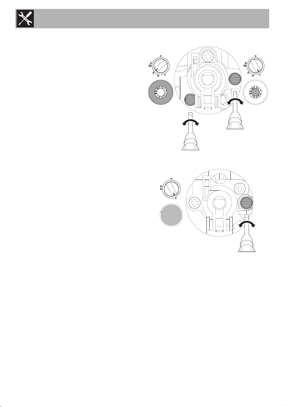
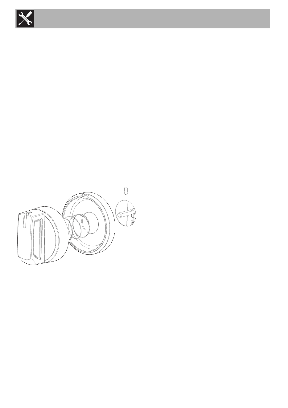
Minimum adjustment for natural Gas
Light the burner and turn the knob to the
minimum position. Remove the gas tap knob
and turn the adjustment screw at the side of
the tap rod until the desired minimum flame
is achieved. Refer to the following pictures.
• Dual Flame burner:
•Rapid burner:
Refit the knob and verify the correct ignition
and burner flame stability (when turning the
knob rapidly from the maximum to the
minimum position the flame must not go out).
Repeat this operation on the remaining gas
taps on the cooktop.
Installation
21
EN
1.5 Conversion to propane gas (LPG)
Always provide an adequate gas supply.
This appliance is shipped from the factory
for use with natural gas. Use this kit to
convert the appliance for use with propane
gas, if necessary. Comply with the
following: Ensure that the range is
converted for use with the appropriate gas
before using it.
This appliance is designed to operate at a
pressure of 10" of water column when used
with propane gas. When checking if the
regulator is working properly, the inlet
pressure must be at least 1" greater than the
operating (manifold) pressure above.
When converting for propane gas use, the
pressure supplied to the regulator must be
between 11" and 13" of the water column.
The pressure regulator located at the inlet of
the range manifold must remain in the
supply line.
Use a flexible metal appliance connector or
rigid pipe to connect the range to the gas
supply. The connector should have an
inside diameter of 1/2” and be 5 ft (1.5 m)
or less in length.
(Exception: Maximum connector length in
Massachusetts installations is 3 ft (0.9 m). In
Canada, the connector must be single-wall
metal and not longer than 6 ft (1.8 m).
Save the nozzles removed from the
appliance for future use.
WARNING
This conversion kit shall be installed by a
qualified service agency in accordance
with the manufacturer’s instructions and
all applicable codes and requirements of
the authority having jurisdiction. If the
information in these instructions is not
followed exactly, a fire, explosion or
production of carbon monoxide may
result causing property damage,
personal injury or loss of life. The
professional installation service is
responsible for the proper installation of
this kit. The installation is not proper and
complete until the operation of the
converted appliance is checked as
specified in the manufacturer’s
instructions supplied with the kit.
WARNING
Before proceeding with the gas
conversion, the gas supply must be
turned off before disconnecting the
electrical power.
WARNING
A gas leak test should be performed after
the gas conversion has been carried out.
Installation
22
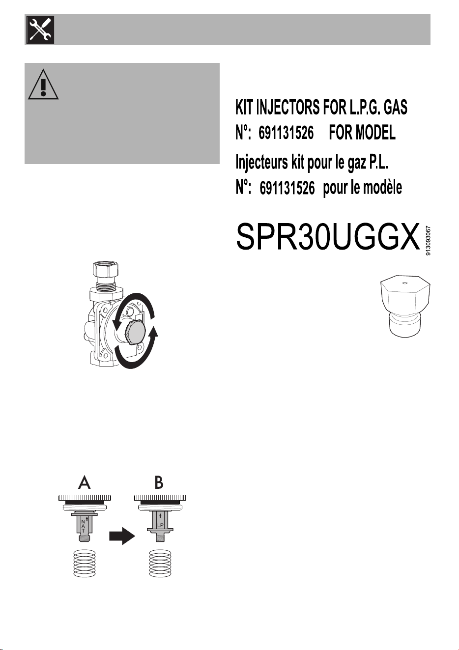
Setting the pressure regulator for
propane gas
To convert the regulator to the type of gas
used, the following must be done:
1. Unscrew the cover of the pressure
regulator.
2. Unscrew the plastic regulator stem from the
regulator cap. Configuration “A” is for
Natural Gas.
3. Invert the plastic regulator stem to achieve
the configuration “B” for Propane Gas and
screw it in tightly.
4. Screw the regulator stem and cap into
place.
List of components
This conversion kit consists of the following
components:
• One label for propane gas injectors
• Two injectors Ø 0.94 mm for
the Reduced Rapid burner.
• One injector Ø 1.02 mm for
the Rapid burner.
• One injector Ø 0.48 mm for
the Ultra-rapid Dual burner (internal
crown).
• One injector Ø 1.15 mm for the Ultra-
rapid Dual burner (external crown).
• One injector Ø 1.20 mm for the Oven
burner.
• One injectors Ø 0.85 mm for the Broiler
burners.
CAUTION
Before proceeding with the gas
conversion, the gas supply must be
turned off before disconnecting the
electrical power.
Installation
23
EN
One change injectors warning label
• One sealing gasket
12.5x18.5x2 (mm).
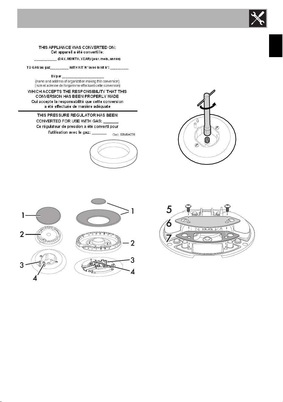
Replacing cooktop
burner nozzles
1. Remove all the grates and all the burner
caps (1) and heads (2);
2. Unscrew the burner nozzles using a 7
mm socket wrench;
3. Replace the nozzles.
4. Put the burners back in their correct
position. Make sure that the holes of the
flame-spreader crowns are aligned with
the thermocouples (3) and igniters (4).
Rapid burner
Unscrew the burner nozzles with a 7 mm
socket wrench and replace them according
to the type of gas to be used and the
description in section ”Burner and nozzle
characteristics tables”.
Dual Flame burner
1. Remove the tightening screws (5), the
cover plate (6) and the gasket (7).
2. Remove the internal (8) and external (9)
nozzles and replace them according to
the type of gas to be used and the
description in section ”Burner and nozzle
characteristics tables”.
Installation
24
3. Refit the burner components correctly.
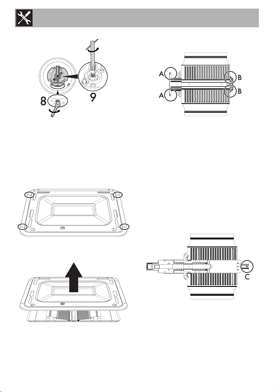
Replacing the oven burner nozzle
1. Open the door.
2. Completely remove all accessories from
inside the oven.
3. Remove the screws on the bake chamber
cover
4. Lift up the oven surface and pull it
outwards.
5. Loosen the screws A and remove the
burner fixing plate.
6. Loosen the screws B.
7. Move away the lock that secures the
thermocouple and igniter to the burner.
8. Slide the burner outwards until the nozzle
is accessible.
9. Replace the nozzle using a 7mm socket
wrench.
Replacing the gas grill nozzle
1. Open the door.
2. Completely remove all accessories from
inside the oven.
3. Loosen the screw C.
4. Slide the burner outwards until the nozzle
is accessible.
Installation
25
EN
5. Replace the nozzle using a 7mm socket
wrench.
6. After having replaced the nozzle, put the
burner back in its seat.
7. Tighten the burner fastening screws.
8. Replace the shelf in its seat.
Minimum adjustment for propane
gas:
Turn off the burners and unplug the
appliance from the electric power supply.
To regulate the minimum flame for propane,
turn the screws at the side of the tap rod
fully clockwise. Once the regulation has
been completed, replace the seal on the
by-passes using paint or similar materials.
Check the appearance of the flames
• Yellow flames: Further adjustment is
required.
• Yellow tips on outer cones: Normal for
propane gas.
• Soft blue flames: Normal for Natural
Gas.
• Orange flames: Can be normal if certain
types of humidifiers are used in the
home. Flames should return to blue
without the humidifier running.
If the flame is completely or mostly yellow,
verify that the regulator is set for the correct
fuel. Retest after adjustment.
Some yellow streaking is normal during the
initial startup. Allow the appliance to
operate for 4–5 minutes and reevaluate
before making adjustments.
The tightening torque of the nozzle
must be 4 Nm.
Take care not to damage the
thermocouple or the igniter when
doing this.
Installation
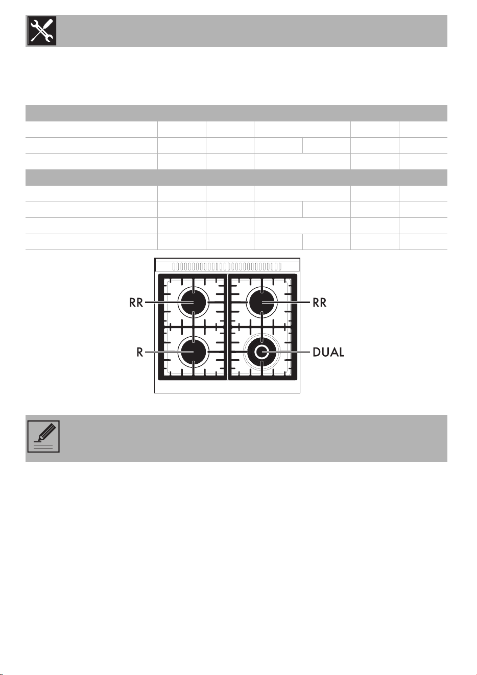
26
Burner and nozzle characteristics tables
To adjust the range for propane gas or to return to using Natural Gas, refer to the charts
below.
Natural Gas RR R DUAL int DUAL ext
Oven Broiler
QT (BTU)
10000 12000 18000 17000 9000
Injector Ø (mm)
1.40 1.52 0.75 1.80 1.80 1.30
QR (BTU)
2500 2500 1000 3000 -
Propane RR R DUAL int DUAL ext
Oven Broiler
QT (BTU)
10000 12000 18000 17000 9000
Injector Ø (mm)
0.94 1.02 0.48 1.15 1.20 0.85
QR (BTU)
2500 2500 1000 3000 -
By-pass (mm)
0.45 0.45 0.30 0.55 0.53 -
NOTE: Save the nozzles that were removed from the appliance along with these
instructions for possible future use.
Installation
27
EN
• Connect the gas supply line to the unit
pressure regulator using a 1/2” flex gas
line connector between the manual shut-
off valve and the pressure regulator. A
metal flex line or fixed metal pipe must
be used to connect the gas to the
appliance. If a metal gas line cannot be
used, consult your local certified
electrician or local electric codes for
proper grounding.
• Check the supply line connections for
leaks using a soap solution or non-
corrosive leak detection fluid. Do not use
a flame of any sort.
1. Turn on gas.
2. Apply a soap solution or non-corrosive
leak detection fluid to all joints and
fittings in the gas connection between the
shut-off valve and the cooktop. Include
gas fittings and joints in the cooktop if
connections may have been disturbed
during installation. Bubbles appearing
around fittings and connections indicate
a leak.
3. If you detect a leak, turn off the supply
line gas shut-off valve and tighten
connections.
4. Retest for leaks by turning the gas supply
line shutoff valve on. When the leak
check has been completed (no bubbles
appear), the test is complete.
5. Wipe off all residues of the soap solution
or detection fluid.
Important notes for Gas Connection
• The appliance and its individual gas
shutoff valve must be disconnected from
the gas supply piping system during
pressure testing of the system at test
pressures in excess of 1/2 psi (3.5kPa).
• The appliance must be isolated from the
gas supply piping system by turning off
its individual manual shut-off valve during
pressure testing of the gas supply piping
system at test pressures equal to or less
than 1/2 psi (3.5kPa).
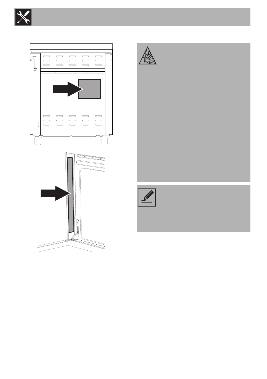
Final operations
• Completely fill out the conversion label
(part no. 92849A078) and attach it to
the rear of the appliance. Do not cover
any other labels with the conversion
label.
• Over time, the gas taps may become
difficult to turn and jam. Clean them
internally and replace the lubrication
grease.
WARNING
Install a gas shutoff valve near the
appliance. After installation, it must be
easily accessible in an emergency.
NOTE: Lubrication of the gas taps
should be performed by a
specialized technician.
Installation
28
• Save the nozzles removed from the unit
along with these instructions for possible
future use.
• For installation of the appliance at high
altitude, please consult your local gas
company for their recommendation on
the correct orifice sizes and any other
necessary adjustments that will provide
proper gas combustion at specified
altitudes.
Lubricating the surface burner gas
valves
Over time, the surface burner gas valves
may become stiff or jam. Clean them
internally and re-lubricate. This operation
must be carried out by a qualified
technician.
Conversion to natural gas
This appliance is shipped from the factory
for use with natural gas. If the appliance
was previously converted to propane gas,
you have to convert it back to natural gas.
Check the orifices for the right nozzles and,
if required, replace them. Adjust the
minimum gas flow.
The optimum setting is achieved when the
height of the small flame is approx.
1
/
8
"
(3 to 4 mm).
Set the pressure regulator for natural gas.
Turn the spring plate the other way around
as shown in ”Setting the pressure regulator
for propane gas”.
Save the nozzles removed from the
appliance for future use.
Installation
29
EN
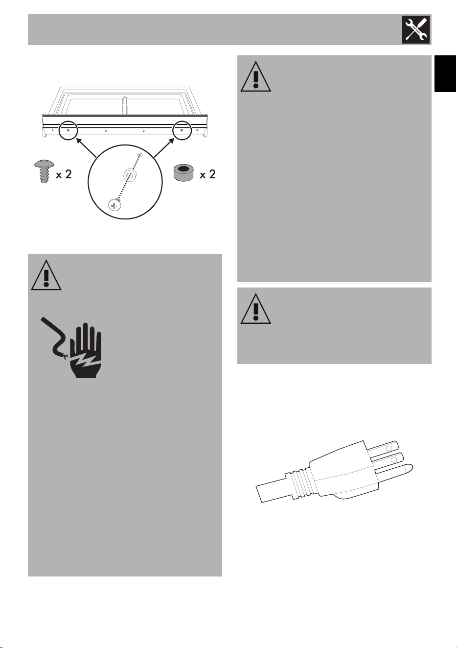
1.6 Wall and floor attachment
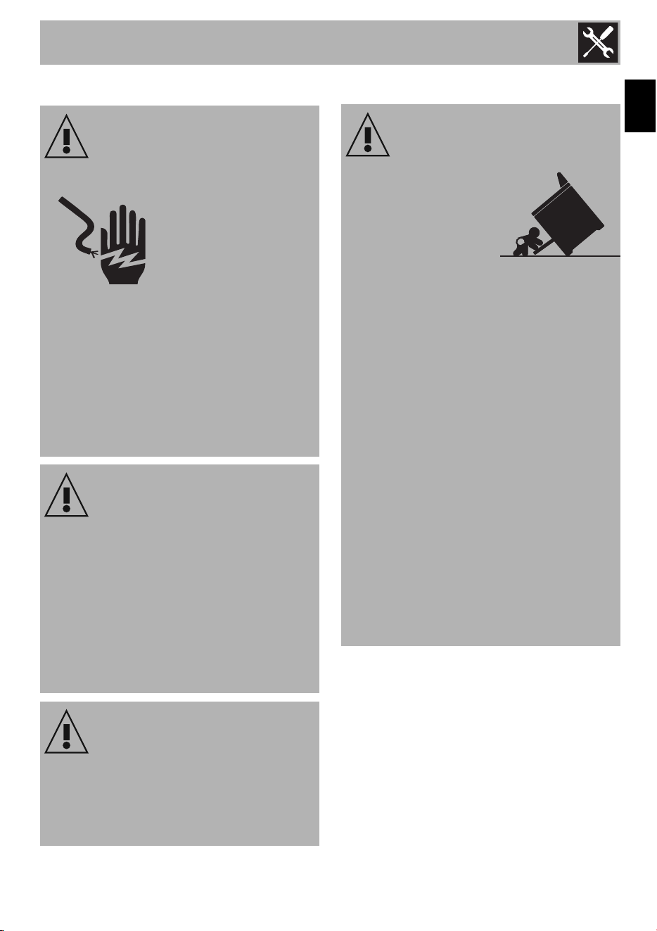
WARNING
Electrical shock hazard
•Use extreme caution
when drilling holes in the
wall or floor. There may
be concealed electrical
wiring behind the wall or
under the floor.
• Identify the location of the electrical
circuits that could be affected by the
installation of the anti-tip device, then
turn off power to these circuits.
• Failure to follow these instructions may
result in electrical shock or other
personal injury.
CAUTION
• Contact a qualified installer or
contractor to determine the proper
method for drilling holes through the
wall or floor material (such as ceramic
tile, hardwood, etc.)
• Failure to follow these instructions may
result in damage to wall or floor
coverings.
WARNING
Visually check from the inside of the
drawer that the wall/floor-mounted
bracket is inserted into the appropriate
lateral hook (left side).
WARNING: Tip Over Hazard
• A child or adult
could tip the
range over and
be killed.
• Install the anti-tip
device on the floor or wall as per
the installation instructions.
• Engage the range with the anti-
tip device as per the installation
instructions.
• Ensure the anti-tip device is re-
engaged when the range is
moved.
• Do not operate the range
without the anti-tip device in
place and engaged.
• See installation instructions for
details.
• Failure to follow these
instructions can result in death or
serious burns to children and
adults.
Installation
30
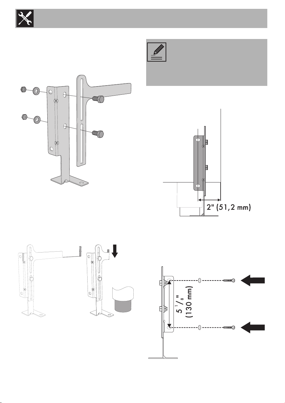
Installing the anti-tip bracket
1. Ensure that the electrical connection is in
the correct position.
2. Assemble the bracket.
3. Align the base of the hook of the bracket
with the base on the slot of the rear wall
fastening bracket. Align the base of the
fastening bracket with the floor and
tighten the screws to fix the
measurements.
4. For wall mounting, go to steps 5, 6, 9
and 10. For floor mounting, to steps 7, 8
and 10.
5. Use the specified distance from the side
of the appliance to the bracket holes.
6. Move the bracket to the wall and fix with
the two washers and screws. A qualified
technician must verify the suitability of the
materials in accordance with the type
and condition of the wall.
NOTE: The wall attachment is
recommended if the appliance is
placed against a wall. Floor
attachment is recommended in
case of island installation.
Installation
31
EN
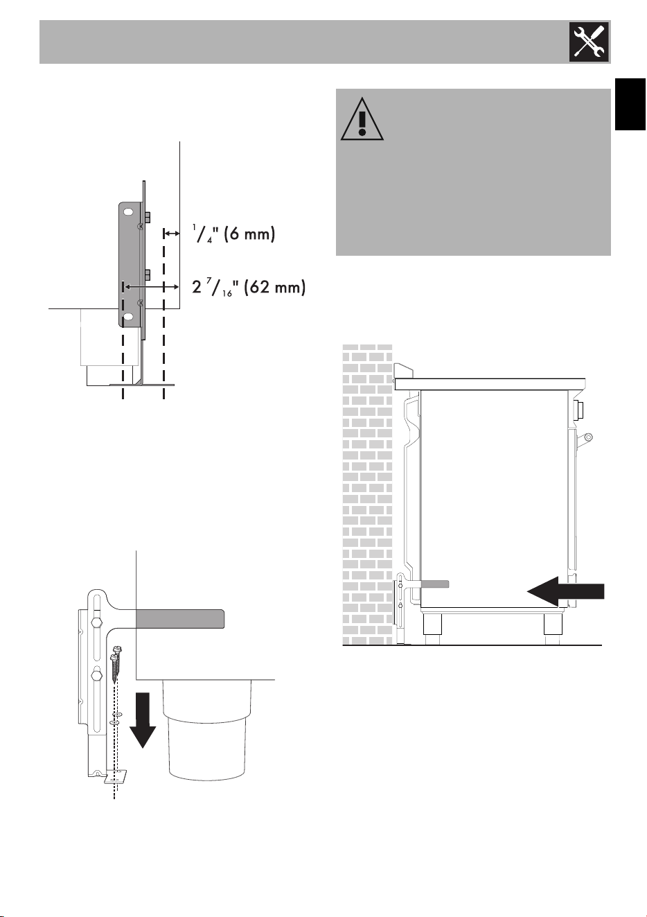
7. Use the following distances for the
distance from the side of the appliance
to the bracket holes.
8. After having positioned and leveled the
appliance, move the bracket close to the
rear of the appliance and anchor it to the
floor using the two washers and screws.
A qualified technician must verify the
suitability of the materials in accordance
with the type and condition of the floor.
9. Push the cooker towards the wall, and at
the same time, insert the bracket in the
plate that is fastened to the rear of the
appliance.
10. Check for proper installation and use of
the anti-tip bracket. Carefully tip the
range forward by pulling it from the back
to ensure that the anti-tip bracket
engages the range leg and prevents tip-
over. The range should not move more
than 1” (2.5cm).
WARNING
The rear vent trim has
3
/
16
” (5 mm)
standoffs to keep the appliance slightly
away from the back wall. Do not remove
or tamper with standoffs due to potential
temperature issues.
Installation
32
Door removal
It is not necessary to remove the door in
order to install the range, but is an added
convenience. Refer to the Use and Care
Guide for the oven door removal
instructions.
1.7 For the installer
• The plug must remain accessible after the
installation is complete. Do not kink or
trap the mains connection cable.
• The appliance must be fitted according
to the installation diagrams.
• When satisfied with the appliance,
please instruct the user on the correct
method of operation.
• Do not attempt to turn or stress the
threaded elbow on the manifold. You
risk damaging this part of the appliance,
which may void the manufacturer’s
warranty.
• Before leaving, check all connections for
gas leaks with soap and water. DO
NOT use a naked flame for detecting
leaks.
• Ignite all burners individually and
concurrently to ensure correct operation
of the gas valves, burner and ignition.
• Turn the gas knobs to the low position
and observe stability of the flame for
each burner individually and all
together.
• In case the appliance fails to operate
correctly after all checks have been
carried out, refer to the Authorized
Assistance Center in your area.
• When satisfied with the appliance,
please instruct the user on the correct
method of operation.
• LEAVE THESE INSTRUCTIONS WITH
APPLIANCE AFTER INSTALLATION IS
COMPLETE.