Table of Contents
3
EN
1Installation 15
1.1 Dimension Requirements 15
1.2 Product dimensions 16
1.3 Unpacking, moving and positioning the range 17
1.4 Wall attachment and anti-tip device 18
1.5 Electrical connection 21
1.6 Gas supply requirements 23
1.7 List of component 26
1.8 Replacing cooktop burners nozzles: 26
2 Burner and nozzle characteristics tables 28
2.1 For the installer 31
WARNING: If the instructions in this manual is not followed exactly, a
fire or explosion may result causing property damage, personal injury
or death.
- Do not store or use gasoline or other flammable vapors or liquids in the
vicinity of this or any other appliance.
- WHAT TO DO IF YOU SMELL GAS
• Do not try to light any appliance.
• Do not touch any electrical switch.
• Do not use any phone in your building.
• Immediately call your gas supplier from a neighbor’s phone. Follow the
gas supplier’s instructions.
• If you cannot reach your gas supplier, call the fire department.
- Installation and service must be performed by a qualified installer, service
agency or gas supplier.
NOTE: This appliance must be installed solely and exclusively by a qualified
technician. Any technical procedures must be carried out by an authorized
technician.
Important Safety Instructions
4
The safety messages will inform you of potential hazards, on how to avoid the risk of injury
and what can occur if the instructions are not followed.
READ AND SAVE THESE INSTRUCTIONS - Your safety and the safety of
others are very important.
We have provided many important safety messages throughout this manual and
on the appliance.
Read all the instructions before using the appliance and always obey all safety
messages.
RECOGNIZE SAFETY INFORMATION
This is a safety alert symbol. This symbol alerts you to potential hazards that can
result in severe personal injury or loss of life.
UNDERSTAND SIGNAL WORDS
A signal word - DANGER, WARNING or CAUTION - is used with the safety alert
symbol. DANGER denotes the most serious hazards. It means you could lose your
life or be seriously injured if you do not immediately
follow the instructions.
WARNING means you could lose your life or be seriously injured if the instructions
are not followed. CAUTION indicates a potentially hazardous situation which, if
not avoided, could result in minor to moderate injury.
WARNING
• This appliance is intended for use in the home only.
• Use this appliance only for its intended purpose. The
manufacturer cannot be held liable for damage caused by
improper use of this range.
• This appliance complies with current safety regulations.
Improper use of this range can result in personal injury and
material damage.
• Read all the instructions before installing or using the range
for the first time.
• Keep these operating instructions in a safe place and pass
them on to any future user.
Important Safety Instructions
5
EN
IMPORTANT: Installation, gas connections and grounding must conform to applicable
codes. Observe all codes and ordinances in force.
Do not store or use gasoline or other flammable vapors, liquids or materials near this or any
other appliance.
NOTE: This range is manufactured for use with natural gas. To convert the
appliance to LP/Propane gas, see the instructions in the Gas Conversion Kit
provided in the literature package.
The proper gas supply connection must be available. See “Gas supply
requirements”.
In the State of Massachusetts, the following installation instructions apply:
• Installation and repairs must be performed by a Massachusetts qualified or
licensed contractor, plumber, or gas fitter.
• If using a ball valve, it shall be the T-handle type.
• A flexible gas connector, when used, must not exceed 3 feet.
WARNING: For your safety, the instructions contained in this manual must be
followed to minimize the risk of fire or explosion and to prevent property damage,
personal injury or loss of life.
NOTE: This range is NOT designed for installation in manufactured (mobile)
homes or in recreational vehicles (RVs).
DO NOT install this range outdoors.
WARNING
To reduce the risk of fire, electrical shock, personal injury, or
damage when using the range, follow basic safety precautions,
including the following:
Important Safety Instructions
6
WARNING
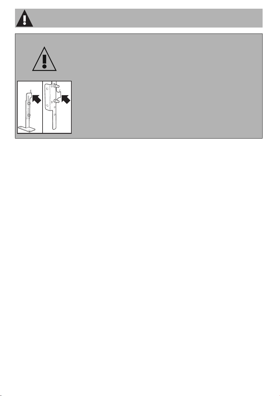
PRIMARY FASTENING SYSTEM:
Visually check that the wall-mounted brackets are inserted into the
appropriate lateral hooks (on both sides).
SECONDARY FASTENING SYSTEM:
Visually check from the inside of the drawer that the floor-mounted
bracket is inserted into the appropriate lateral hooks (left or right).
Important Safety Instructions
7
EN
Important Notes to the Installer
• Read all instructions contained in
these installation instructions
before installing the range.
• Remove all packing material from
the oven and the drawer
compartments before connecting
the electrical and gas supplies to
the range.
• Observe all governing codes and
ordinances. Be sure to leave
these instructions with the
consumer.
Important Note to the Customer
• Keep these instructions with your
owner's guide for future
reference.
Definitions
• This manual contains important
safety symbols and instructions.
Please pay attention to these
symbols and follow all instructions
given.
TIP OVER HAZARD
WARNING
This symbol will help alert you to
situations that may cause serious bodily
harm, death or property damage.
CAUTION
This symbol will help alert you to
situations that may cause injury or
property damage.
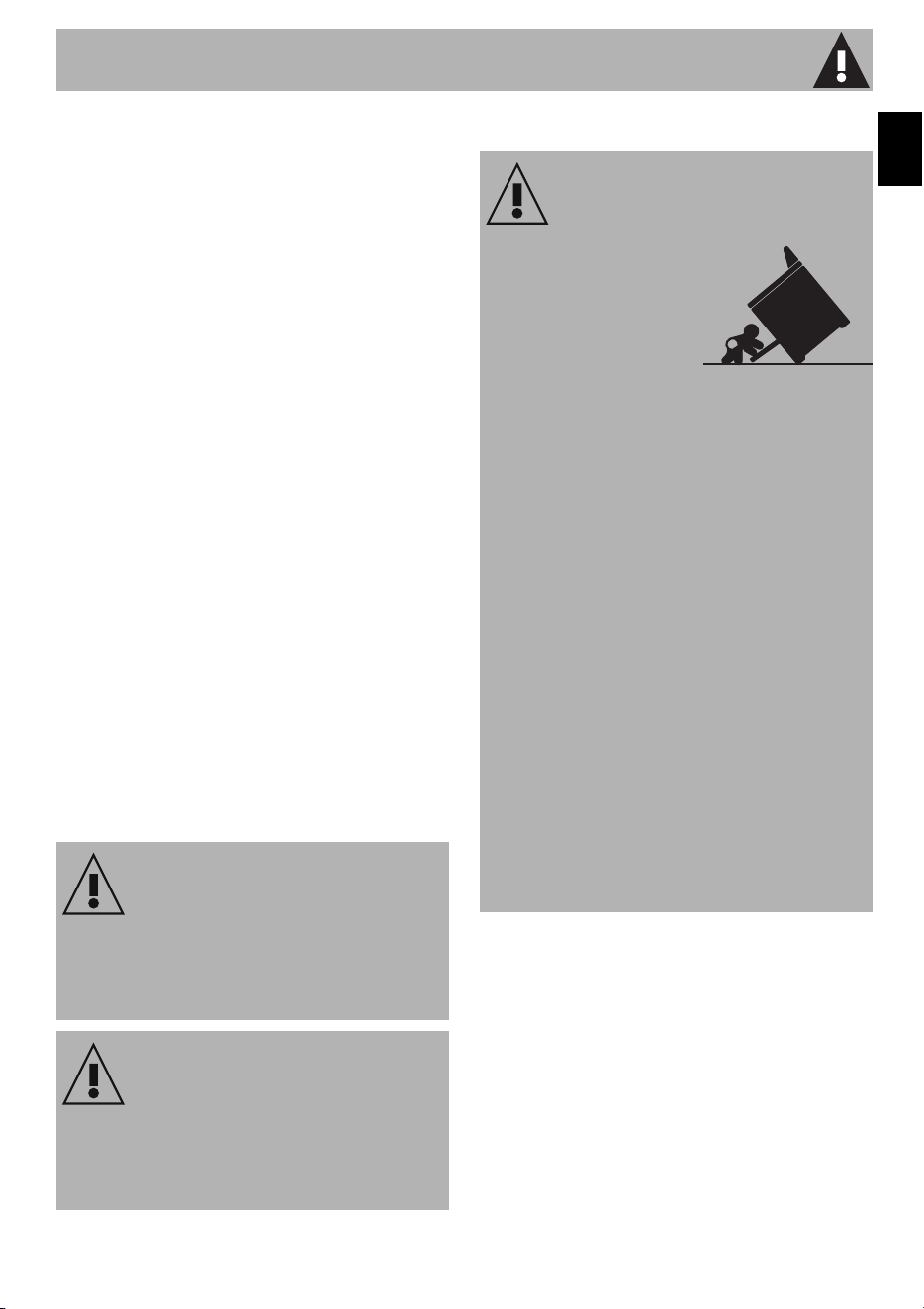
WARNING: Tip Over Hazard
• A child or adult
could tip the
range over and
be killed.
• Install the anti-tip
device on the floor or wall as
per the installation instructions.
• Engage the range with the anti-
tip device as per the installation
instructions.
• Ensure the anti-tip device is re-
engaged when the range is
moved.
• Do not operate the range
without the anti-tip device in
place and engaged.
• See installation instructions for
details.
• Failure to follow these
instructions can result in death or
serious burns to children and
adults.

Important Safety Instructions
8
• Check for proper installation and
use of the anti-tip bracket.
Carefully tip the range forward
by pulling it from the back to
ensure that the anti-tip bracket
engages the range leg and
prevents tip-over. The range
should not move more than 1”
(2.5cm).
Appliance Handling Safety
Hidden surfaces may have sharp
edges. Use caution when reaching
behind or under the appliance.
• Wear gloves to avoid cutting
fingers on sharp edges during
installation.
• The unit is heavy and requires at
least two persons or proper
equipment to move it.
• Do not lift appliance by the oven
door handle. Remove the oven
door for easier handling and
installation.
• Do not use the oven for storage.
Safety Codes and Standards
This appliance complies with one or
more of the following Standards:
ANSI Z21.1/CSA 1.1 Household
Cooking Gas Appliances.
UL 858 - The Standard for the
safety of Household Electric
Ranges.
CAN/CSA-C22.2 No. 61
Household Cooking Ranges.
• It is the responsibility of the owner
and the installer to determine
whether additional requirements
and/or standards apply to
specific installations.
• Installation must conform with
local codes or, in the absence of
local codes, with the National
Fuel Gas Code, ANSI Z223.1/
NFPA 54 or, in Canada, the
Natural Gas and Propane
Installation Code, CSA B149.1.
• The appliance must be electrically
grounded in accordance with
local codes or, in the absence of
local codes, with the National
Electrical Code, NFPA 70 latest
edition or, in Canada, the
Canadian Electric Code, CSA
C22.1-02.
• Before installing the range in an
area covered with linoleum or
any other synthetic floor covering,
make sure the floor covering can
withstand heat at least 90°F
above room temperature without
shrinking, warping or discoloring.
To check if the anti-tip
bracket is installed
properly, use both arms
and grasp the back edge
of the range. Carefully
attempt to tilt the range forward. When
properly installed, the range should not
tilt forward.
Refer to the anti-tip bracket installation
instructions supplied with your range for
proper installation.
Important Safety Instructions
9
EN
Do not install the range over
carpeting unless you place an
insulating pad or sheet of ¼"
(10,16cm) thick plywood
between the range and
carpeting.
• Be sure your range is installed
and grounded properly by a
qualified installer or service
technician.
• Make sure the wall coverings
around the range can withstand
the heat generated by the range.
• Do not store items of interest to
children in the cabinets above the
range. Children could be
seriously burned if they climb on
the range to reach items.
• To eliminate the need to reach
over the surface burners, cabinet
storage space above the burners
should be avoided.
• Do not use the oven as a storage
space. This creates a potentially
hazardous situation.
• Do not store or use gasoline or
other flammable vapors and
liquids near this or any other
appliance. Explosions or fires
could result.
• Adjust the size of the surface
burner flame so it does not extend
beyond the edge of the cooking
utensil. An excessive flame is
hazardous.
• Never use your range for
warming or heating the room.
Prolonged use of the range
without adequate ventilation can
be dangerous.
• In the event of an electrical power
outage, the surface burners can
be lit manually. To light a surface
burner, hold a lit match to the
burner head and slowly turn the
Surface Control knob to LITE. Use
caution when lighting surface
burners manually.
• Unlike the standard gas range,
THIS COOKTOP IS NOT
REMOVABLE. Do not attempt to
remove the cooktop.
WARNING
Never leave children alone or
unattended in the area where an
appliance is in use. As children grow,
teach them the proper, safe use of all
appliances. Never leave the oven door
open when the range is unattended.
CAUTION
Stepping, leaning or sitting on the doors
or drawers of this range can result in
serious injuries and can also cause
damage to the range.
Important Safety Instructions
10
Electric Safety
• Personal injury or death from
electrical shock may occur if the
appliance is not installed by a
qualified installer or electrician.
• Make sure your appliance is
properly installed and grounded
by a qualified electrician.
Installation, electrical connections
and grounding must comply with
all applicable codes.
• Before installing, turn power OFF
at the service panel. Lock service
panel to prevent power from
being turned ON accidentally.
• For appliances equipped with a
cord and plug, do not cut or
remove the ground prong. It must
be plugged into a matching
grounding type receptacle to
avoid electrical shock. If there is
any doubt as to whether the wall
receptacle is properly grounded,
the customer should have it
checked by a qualified
electrician.
• Do not use an extension cord.
• Do not use an adapter.
• If required by the National
Electrical Code (or Canadian
Electrical Code), this appliance
must be installed on a separate
branch circuit.
• The circuit breaker should have a
contact separation of at least 3 mm
on all poles.
• INSTALLER – show the owner the
location of the circuit breaker or
fuse. Mark it for easy reference.
• Refer to rating label for more
information.
WARNING
Do not repair, replace or remove any
part of the appliance unless specifically
recommended in the manuals. Improper
installation, service or maintenance can
cause injury or property damage. Refer
to this manual for guidance. All other
servicing should be done by an
authorized service provider.
WARNING
Before you plug the electrical cord into
an outlet, make sure that all the
appliance controls are in the OFF
position.
Important Safety Instructions
11
EN
Gas safety
• Install a gas shutoff valve near the
appliance. It must be easily
accessible in an emergency.
• Leak testing must be conducted
by the installer according to the
instructions in this manual.
• The appliance and its individual
shutoff valve must be
disconnected from the gas supply
piping system during any pressure
testing at pressures in excess of ½
psi (3.5 kPa).
• The appliance must be isolated
from the gas supply piping system
by turning off its individual manual
shutoff valve during pressure
testing of the gas supply piping
system at test pressures equal to
or less than ½ psi (3.5 kPa).
• The minimum supply pressure must
be 1" water column above the
manifold pressure printed on the
rating label. The maximum supply
pressure of 14.0 inches water
column (34.9 Millibars) must not
exceed.
• IMPORTANT SAFETY NOTICE
Burning gas cooking fuel
generates some by products
which are on the list of substances
which are known by the State of
California to cause cancer or
reproductive harm. To minimize
exposure to these substances,
always operate this unit
according to the instructions
contained in this booklet and
provide good ventilation.
Proposition 65 Warning:
This product may contain a chemical known
to the State of California, which can cause
cancer or reproductive harm. Therefore, the
packaging of your product may bear the
following label as required by California:
WARNING
Burning gas cooking fuel generates some
by-products which are on the list of
substances which are known by the State
of California to cause cancer or
reproductive harm. To minimize exposure
to these substances, always operate this
unit according to the instructions
contained in this booklet and provide
good ventilation.
State of California Proposition 65
WARNING
Cancer or Reproductive Harm -
www.P65Warnings.ca.gov

Important Safety Instructions
12
Propane Gas Installation
• The propane gas tank must be
equipped with its own high
pressure regulator. In addition,
the regulator supplied with this
unit must also be used.
• The appliance is shipped from the
factory for use with natural gas. It
must be converted for use with
propane. The conversion must be
done by a qualified technician or
installer.
• This appliance can operate up to
an altitude of 10,000 ft. (3048 m.)
elevation above sea level. For use
with propane gas, the appliance
must be converted in accordance
with the propane conversion
instructions.
For installations in Massachusetts
• Installation must be performed by
a qualified or licensed contractor,
plumber or gas fitter qualified or
licensed by the state, province or
region where this appliance is
being installed.
• Shut-off valve must be a “T”
handle gas cock.
• Flexible gas connector must not
be longer than 36 inches.
• Installer - show the owner where
the gas shut-off valve is located.
Related Equipment Safety
• The appliance should only be
used if installed by a qualified
technician in accordance with
these installation instructions and
all applicable regulations and
codes. The manufacturer is not
responsible for damages resulting
from incorrect installation.
• Remove all tape and packaging
before using the appliance.
Dispose of the packaging after
unpacking the appliance. Never
allow children to play with
packaging material.
• Never modify or alter the
construction of the appliance. For
example, do not remove leveling
legs, panels, wire covers or anti-
tip brackets/screws.
• To eliminate the risk of burns or fire
by reaching over hot surface
units, cabinet storage space
located above the surface units
should be avoided. If cabinet
storage is to be provided, the risk
can be reduced by installing a
hood that projects horizontally a
minimum of 5 inches (127 mm)
beyond the bottom of the cabinet.
Be sure cabinets above the
cooktop are a maximum of 13"
(330 mm) deep.

Important Safety Instructions
13
EN
• When installing a cooktop over a
single oven, be sure to follow
both the oven and cooktop
installation manuals.
Ventilation Recommendations
• Do not obstruct air vents or heat
vent openings.
• We strongly recommend the
installation of a ventilation hood
above this appliance. The hood
must be installed according to the
instructions provided with the
hood.
• Do not obstruct the flow of
combustion air at the oven vent
nor around the base or beneath
the lower front panel of the range.
Avoid touching the vent openings
or nearby surfaces as they may
become hot while the oven is in
operation. This range requires
fresh air for proper burner
combustion.
• Air curtains or other overhead
range hoods, which operate by
blowing air downwards onto a
range, shall not be used in
conjunction with gas ranges other
than when the hood and range
have been designed, tested and
listed by an independent test
laboratory for use in combination
with each other.
High altitude installation
• This appliance can operate up to
an altitude of 10,000 ft.
(3048 m.) elevation above sea
level. If desired, for altitudes
above 2,000 ft (610 m) elevation
above sea level, adjustments may
be made.
• Burners should be checked at the
lowest setting, if the flame is not
stable, the simmer should be
increased until the flame is stable.
This can be done by adjusting the
bypass screw in the valve. If flame
performance is satisfactory,
adjustment will not be required.
• It is required that a Certified
Professional make the high
altitude adjustments during
installation.
• Improper installation is not
CAUTION
The appliance should not be installed
with a ventilation system that blows air
downward toward the burners. This type
of ventilation system may cause ignition
and combustion problems with the gas
cooking appliance and may result in
personal injury or unintended operation.
Important Safety Instructions
14
covered by the warranty.
SAVE THESE INSTRUCTIONS
WARNING
If the information in this manual is not
followed exactly, fire or shock may result
causing property damage or personal
injury.
Installation
15
EN
1 Installation
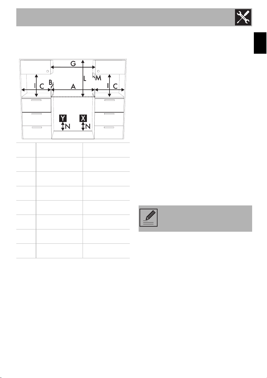
1.1 Dimension Requirements
1. min. clearance from the sides of range to
side wall or other combustible material;
2. min. cabinet opening width;
3. upper cabinet to countertop;
4. min. when bottom of wood or metal
cabinet is protected by not less than ¼”
(0.64 cm) flame retardant millboard
covered with not less than No. 28 MSG
sheet steel, 0.015" (0.4 mm) stainless
steel, 0.024" (0.6 mm) aluminum or
0.020" (0.5 mm) copper. 35" (889 mm)
min. clearance between the top of the
cooking surface and the bottom of an
unprotected wood or metal cabinet.
5. max. upper cabinet depth.
Y - Grounded outlet
Position within 11
7
/
8
" (300 mm) from the
left rear corner of the range.
X - Gas supply line
Position within 11
7
/
8
" (300 mm) from the
right rear corner of the range.
A 1220 mm
48
1
/
16
"
B 636 mm 25“
C
1
216 mm
8
1
/
2
"
G
2
1220 mm
48
1
/
16
"
I
3
457 mm 18"
L
4
610 mm 24"
M
5
330 mm 13"
N 178 mm 7"
NOTE: Install with zero
clearance sides and back.
Installation
16
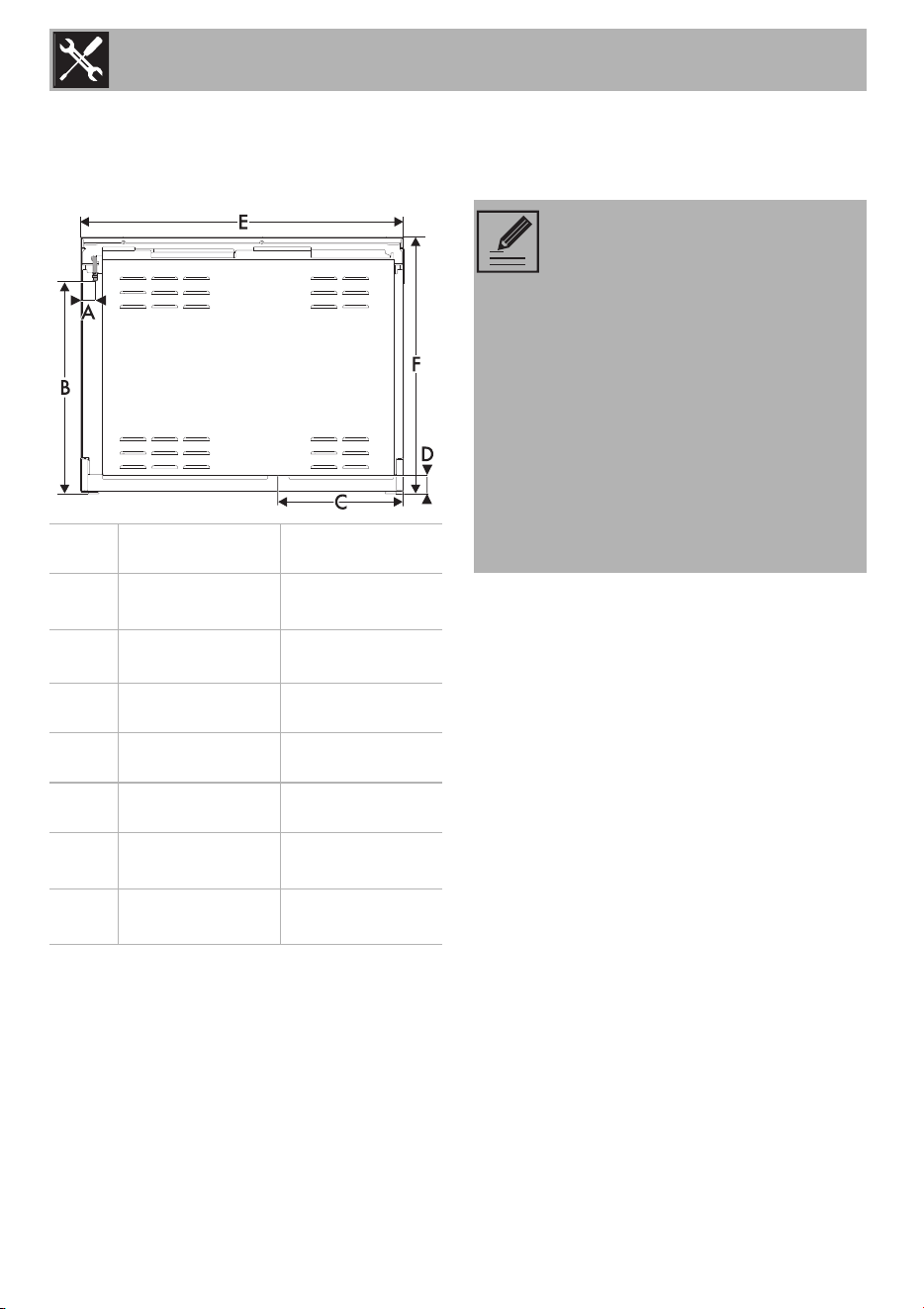
1.2 Product dimensions
Overall dimensions: Location of gas and
electrical connection points.
Check the location where the range is to be
installed. The range should be positioned
for convenient access in the kitchen.
The cabinet opening dimensions that are
shown must be used. The indicated
dimensions are the minimum clearances.
When installing a range under existing
cabinets that do not satisfy the minimum
cabinet clearances, install a rangehood
over the cooking surface to avoid burn
hazards.
A 53 mm
2
1
/
16
"
B
(max)
790 mm
31
2
/
16
"
B
(min)
760 mm
29
15
/
16
"
C 472 mm
18
9
/
16
"
D 57 mm
2
4
/
16
"
E 1217 mm
47
15
/
16
"
F
(max)
942 mm
37
1
/
16
"
F
(min)
912 mm
35
14
/
16
"
NOTE: Observe all governing
codes and ordinances.
Any openings in the wall or floor
where the range is to be installed
must be sealed.
Some cabinet and building
materials are not designed to
withstand the heat that the oven
produces during baking. Check
with your builder or cabinet
supplier to make sure that the
materials used will not discolor,
delaminate or sustain other
damage.
Installation
17
EN
An air curtain or other overhead range
hood, which operates by blowing a
downward airflow onto a range, shall not
be used in conjunction with the gas range
unless the hood and range have been
designed, tested in accordance with ANSI
Z21.1 and listed by an independent testing
laboratory for combination use. This type of
ventilation system may cause ignition and
combustion problems with the gas cooking
appliance resulting in personal injury or
unintended operation.
1.3 Unpacking, moving and
positioning the range
• It is recommended that the grates, the
griddle plate and burner heads, burner
caps, front kick panel and oven racks be
removed to facilitate handling. This will
reduce the weight for moving.
• When positioning the appliance during
installation, do not
use the door handle
to lift up or move this appliance.
• Remove the outer carton and packing
material from the shipping base.
• Remove angle-mounting brackets from
the range.
• Due to the weight, a dolly/fork lift with
soft rubber tread wheels should be used
to move this unit. The weight must be
supported uniformly across the bottom.
• The floor under the legs should be
protected (wood, strips, carpet,
paneling, etc.) before pushing the unit
into position.
• The anti-tip device must be installed, and
the gas and electrical connections
should be made before the range is
placed in its final position.
• Ensure that the burner caps are correctly
positioned on the burner bases on the
rangetop.
• Legs should be installed near to where
the appliance will be used as they are
not secure for long transit. Keep the unit
raised so the legs can be screwed into
their couplings, then lower the range
gently to prevent the legs and mounting
hardware from being subject to any
undue strain. Instead of tilting the unit, it is
recommended that a pallet or lift jack be
used.
CAUTION: This unit is designed as
a cooking appliance. For safety
purposes, never use it for warming
the room or as a space heater.
Installation
18
1.4 Wall attachment and anti-tip device
Warning
Electrical shock hazard
• Use extreme caution when drilling holes into the wall or floor. There may be concealed
electrical wiring located behind the wall or under the floor.
• Identify the location of the electrical circuits that could be affected by the installation of
the anti-tip device, then turn off power to these circuits.
• Failure to follow these instructions may result in electrical shock or other personal injury.
CAUTION
• Contact a qualified installer or contractor to determine the proper method for
drilling holes through the wall or floor material (such as ceramic tile, hardwood,
etc.)
• Failure to follow these instructions may result in damage to wall or floor
coverings.
WARNING
To reduce the risk of fire, electrical shock, personal injury, or
damage when using the range, follow basic safety precautions,
including the following:
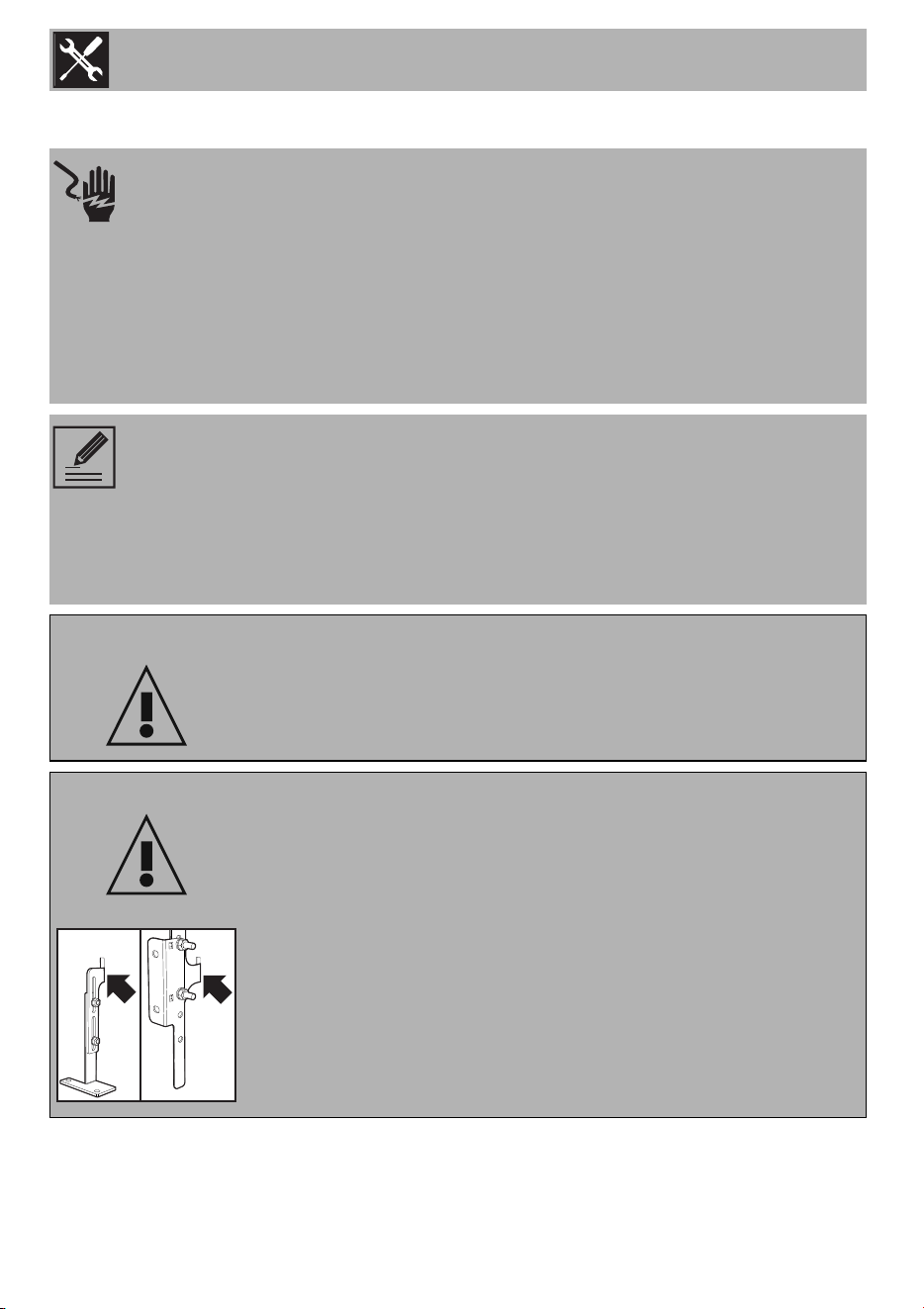
WARNING
PRIMARY FASTENING SYSTEM:
Visually check that the wall-mounted brackets are inserted into the
appropriate lateral hooks (on both sides).
SECONDARY FASTENING SYSTEM:
Visually check from the inside of the drawer that the floor-mounted
bracket is inserted into the appropriate lateral hooks (left or right).
Installation
19
EN
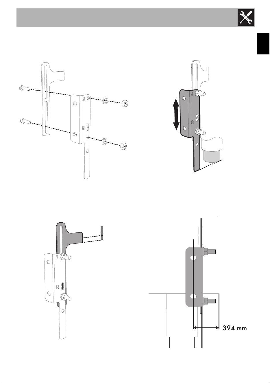
Instructions for wall mounting (primary
system)
1. Assemble the fastening bracket.
2. Align the base of the hook on the
fastening bracket with the base of the
slot on the wall fastening plate.
3. Align the base of the fastening bracket
with the ground and tighten the screws
to fix the measurements.
4. Use 50 mm for the distance from the
side of the appliance to the bracket
holes.
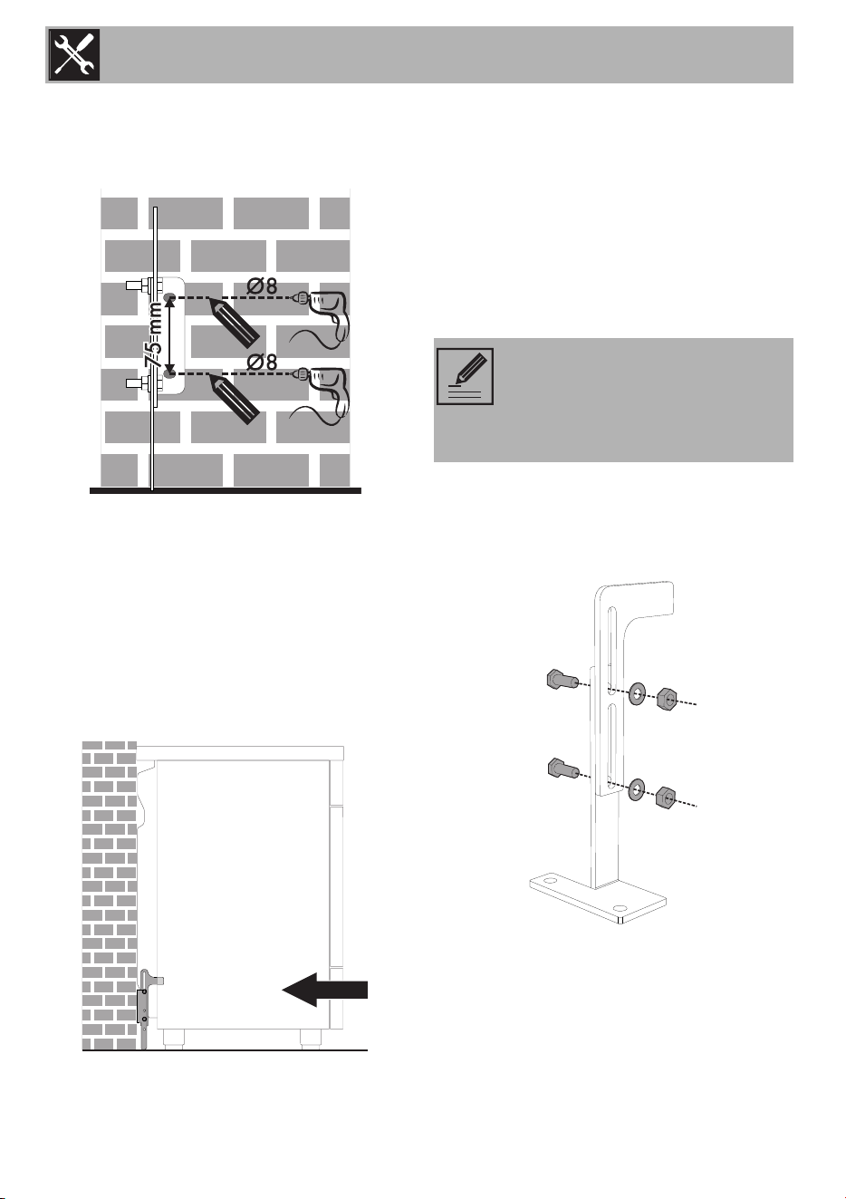
Installation
20
5. Move the bracket onto the wall and
mark the position of the holes to be
drilled in the wall.
6. After drilling the holes in the wall, use
wall plugs and screws to fasten the
bracket to the wall.
7. Push the cooker towards the wall, and
at the same time, insert the bracket in
the plate fastened to the rear of the
appliance.
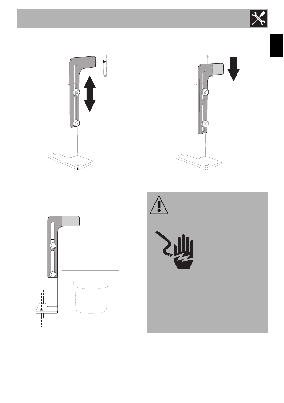
Instructions for floor mounting
(secondary system)
The secondary anti-tip device is to be
attached to the floor when it is not possible
to install the primary system. After having
positioned and leveled the appliance the
bracket has to be anchored to the floor and
engaged in the slots at the rear of the
appliance.
1. Assemble the fastening bracket as shown
in the figure. Join the two parts without
tightening them too much since there will
be other adjustments to make.
NOTE: According to the type of
floor, the installer should supply the
suitable fastening systems (Type of
screw recommended
3
/
8"
).
Installation
21
EN
2. The bracket attachment should insert into
one of the central slots at the rear.
3. After having positioned and leveled the
appliance, move the bracket close to the
rear of the appliance and anchor it to the
floor.
4. Lower the bracket attachment until
anchoring the appliance slot, tighten the
nuts previously assembled. The anti-tip
device works properly only if the bracket
attachment is securely anchored to the
appliance.
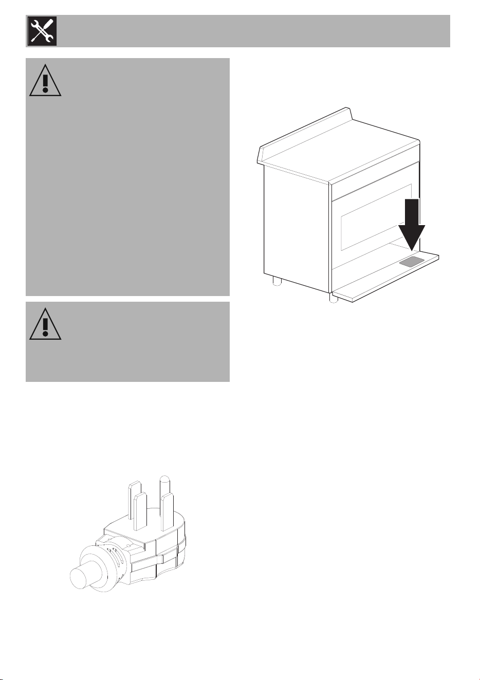
1.5 Electrical connection
WARNING
Electrical shock hazard
•This appliance is
equipped with a four-
prong grounding plug for
your protection against
electric shock and should
be plugged directly into a properly
grounded receptacle. Do not cut or
remove the grounding prong from this
plug.
• Failure to do any of the above could
result in a fire, personal injury or
electrical shock.
Installation
22
This range is equipped with a factory-
connected power cord. The cord must be
connected to a grounded 120/240 volt or
120/208 volt outlet. If no outlet is
available, have one installed by a qualified
electrician.
Make sure that the power line rating
matches the specifications indicated on the
ID plate. The ID Plates are visibly located
on the back of the appliance and on the
oven door frame.
These ID plates must never be removed.
WARNING
Electrical shock hazard
• Disconnect the electrical supply before
servicing the appliance
• It is the personal responsibility of the
consumer to have the appropriate outlet
or junction box with the correct, properly
grounded wall receptacle installed by a
qualified electrician. It is the
responsibility and obligation of the
consumer to contact a qualified installer
to ensure that the electrical installation is
suitable and in conformance with all
local codes and ordinances.
CAUTION
Do not use multiple outlets, extension
cords or adapters.
Installation
23
EN
1.6 Gas supply requirements
This installation must conform with all local
codes and ordinances. In the absence of
local codes, installation must conform to
American National Fuel Gas Code, ANSI
Z223.1/NFPA 54 or, in Canada, the
Natural Gas and Propane Installation
Code, CSA B149.1.
If local codes permit, a flexible metal
appliance conductor with the new AGA or
CSA design certified, 4-5 feet (1.2-1.5 m)
long,
1
/
2
" or
3
/
4
" ID NPT, is
recommended for connecting this range to
the gas supply line.
Do not bend or damage the flexible
connector when moving the range. The
pressure regulator has 3/8" female pipe
threads. You will need to determine the
fittings required, depending on the
dimension of your gas supply line, the
flexible metal connector and the shut-off
valve.
The appliance should be installed in rooms
that have a permanent air supply in
accordance with the standards in force. The
room where the appliance is installed must
have enough air flow for the regular
combustion of gas and the necessary air
change in the room itself. The air vents,
protected by grilles, must be the right size to
comply with current regulations and
positioned so that no part of them is
obstructed, not even partially.
The room must be kept adequately
ventilated in order to eliminate the heat and
humidity produced by cooking: in
particular, after prolonged use, you are
recommended to open a window or to
increase the speed of any fans.
Warning
Explosion hazard
• Use a new AGA or CSA-approved gas
supply line.
• Install a shut-off valve.
• Securely tighten all gas connections.
• lf connected to LP, have a qualified
technician ensure that the gas pressure
does not exceed a 14" W.C.P.
• Examples of qualified technicians
include licensed heating personnel,
authorized gas company personnel,
and authorized service personnel.
• Failure to do so can result in loss of life,
explosion, or fire.
NOTE:
• Observe all codes and
ordinances in force.
• The range must be connected to
a standard gas supply.
Installation
24
Gas connection
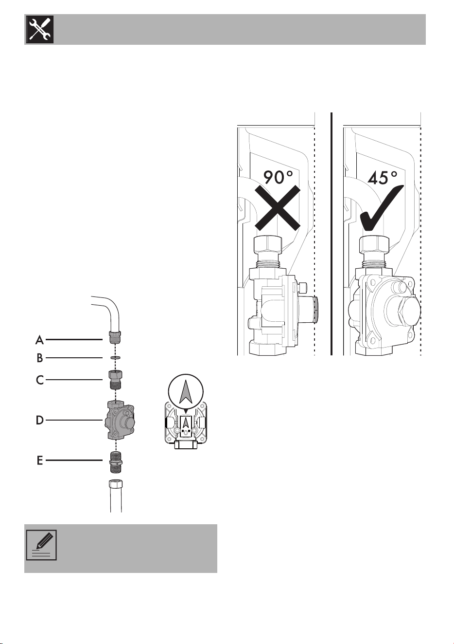
Connect the adapter C (ISO 228/1 -
½ NPT) to the gas inlet of the appliance A
being sure to insert the supplied gasket B.
Apply a suitable sealing substance (such as
Teflon tape) between pressure regulator D
and adapter C.
Connect the pressure regulator D to the
adapter C put on in the previous step (the
arrow on the back of the regulator points
towards the gas inlet of the appliance).
Apply a suitable sealing substance (such as
Teflon tape) between pressure regulator D
and adapter E (½ NPT - ½ NPT) (not
supplied).
Connect the adapter E to the pressure
regulator D.
Due to problems of overall dimensions at
the back, screw in the pressure regulator so
that it is sloped at 45° vs the wall at the
back of the appliance.
WARNING: The tightening torque
of adapter (C / E) must not be
greater than 36 ozf - 10 Nm.
Installation
25
EN
Test the appliance
Follow these instructions to leak test the
appliance:
Use a brush and liquid detergent to test all
gas connections for leaks. Bubbles around
connections indicate a leak. If a leak
appears, shut off the gas valve controls and
adjust the connections. Then check the
connections again. Remove all the
detergent product from the range. Replace
the parts on the burner and turn the knobs
on the gas tap valves.
NEVER TEST FOR GAS LEAKS WITH A
MATCH OR OTHER FLAMES.
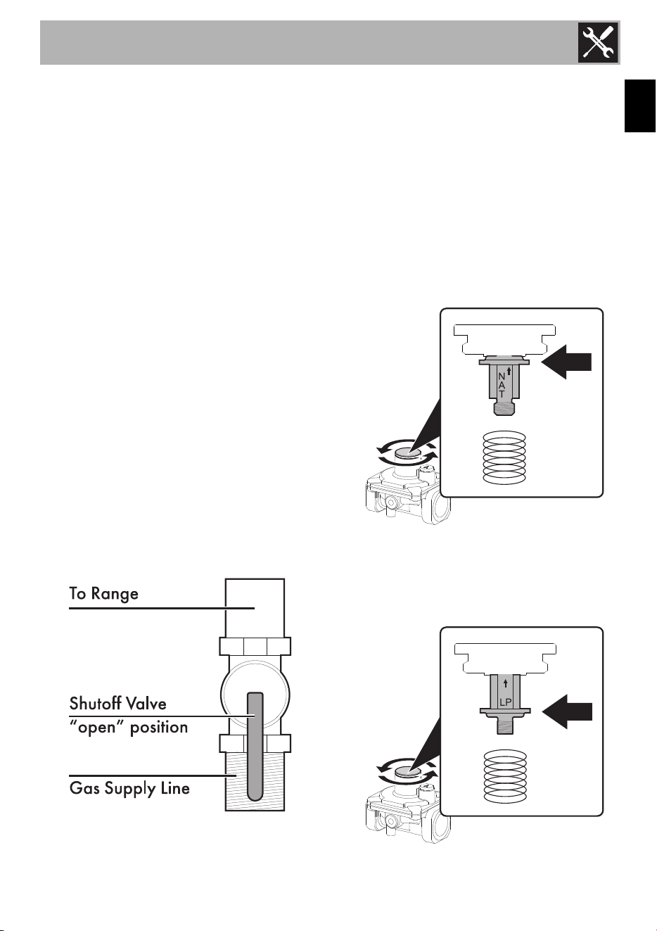
Shut-off valve
The supply line must be fitted with an
approved shut-off valve.
This valve should be located in the same
room as the range and should be in a
location where it can be easily opened and
closed.
Do not block access to the shut-off valve.
The valve is necessary for turning the gas to
the appliance on or off.
Incoming line pressure
Incoming line pressure upstream from the
regulator must be 1” (2.5 cm) W.C.P. higher
than the manifold pressure in order to check
the regulator. Incoming line pressure to the
regulator should be as follows for operation
and checking the regulator setting:
• Natural Gas: Set pressure to 5” W.C.P.
Incoming line pressure of 6” - 10 1/2”
W.C.P maximum.
• LP Gas: Set pressure to 10” W.C.P.
Incoming line pressure 11”- 13” W.C.P.
maximum.
Installation
26
1.7 List of component
This conversion kit consists of the following
components:
• One label for LPG injectors
• One injector Ø 0.65 mm for
the Auxiliary burners.
• One injector Ø 0.80 mm for
the Semi-rapid burner.
• Two injectors Ø 1.02 mm for
the Rapid burners.
• One injector Ø 0.48 mm for the Ultra-
rapid Dual burner (internal crown).
• One injector Ø 1.15 mm for the Ultra-
rapid Dual burner (external crown).
• One warning label change injectors
• One seal gasket
12.5x18.5x2 (mm).
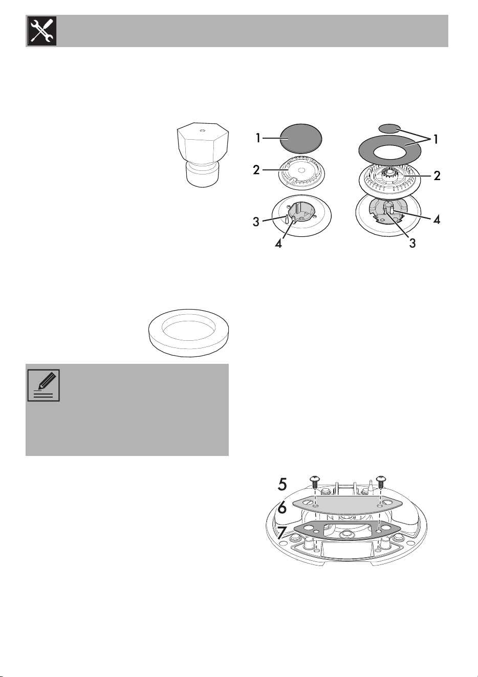
1.8 Replacing cooktop burners
nozzles:
1. Remove all the grates and all the burner
caps (1) and heads (2);
2. Unscrew the burner nozzles with a 7 mm
socket wrench;
3. Replace the nozzles according to the
type of gas to be used and the
description in section 3.2 “Burner and
nozzle characteristics table”.
4. Put the burners back in their correct
position. Make sure that the holes of the
flame-spreader crowns are aligned with
the thermocouples (3) and igniters (4).
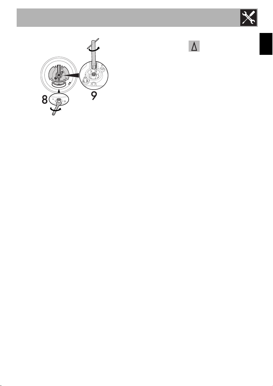
For the Ultra Rapid burner (UR2)
1. Remove the tightening screws (5), the
cover plate (6) and the gasket (7).
2. Remove the internal (8) and external (9)
nozzles and replace them according to
the type of gas to be used and the
description in section “Burner and nozzle
characteristics tables”.
NOTE: The range must be isolated
from the gas supply piping system
by turning off the respective
manual shut-off valve during any
pressure testing of the gas supply
piping system.
Installation
27
EN
Refit the burner components correctly.
Test the appliance
Follow these instructions to leak test the
appliance:
Use a brush and liquid detergent to test all
gas connections for leaks. Bubbles around
connections indicate a leak. If a leak
appears, shut off the gas valve controls and
adjust the connections. Then check the
connections again. Remove all the
detergent product from the range. Replace
the parts on the burner and turn the knobs
on the gas tap valves.
NEVER TEST FOR GAS LEAKS WITH A
MATCH OR OTHER FLAMES.
Check that the flame at the maximum flame
position has a blue color. It should be clean
and soft in character. No blowing or lifting
of flame should occur. Occasional orange
flashes are normal and reflect different
elements in the air or gas.
Wipe away all the detergent product from
the range.
Replace the parts on the burner and turn the
knobs on the gas tap valves.
Minimum adjustment
For natural Gas:
Light the burner and turn the knob to the
minimum position . Remove the gas tap
knob and turn the adjustment screw at the
side of the tap rod until the desired minimum
flame is achieved.
Refit the knob and verify that the burner
flame is stable (when turning the knob
rapidly from the maximum to the minimum
position the flame must not go out).
Repeat this operation on the remaining gas
taps on the cooktop.
For LP Gas:
Turn off the burners and unplug the
appliance from the electrical power supply.
For regulating the minimum with LP, the
screws at the side of the tap rod must be
turned clockwise all the way. Once the
regulation has been completed, replace the
seal on the by-passes using paint or similar
materials. Follow the instructions given in
point 9 to locate the adjustment screws.
Installation
28
2 Burner and nozzle characteristics tables
To adjust the range for LP gas or to return to Natural Gas use, refer to the charts below.
NOTE: Save the nozzles that were removed from the appliance along with these
instructions for possible future use.
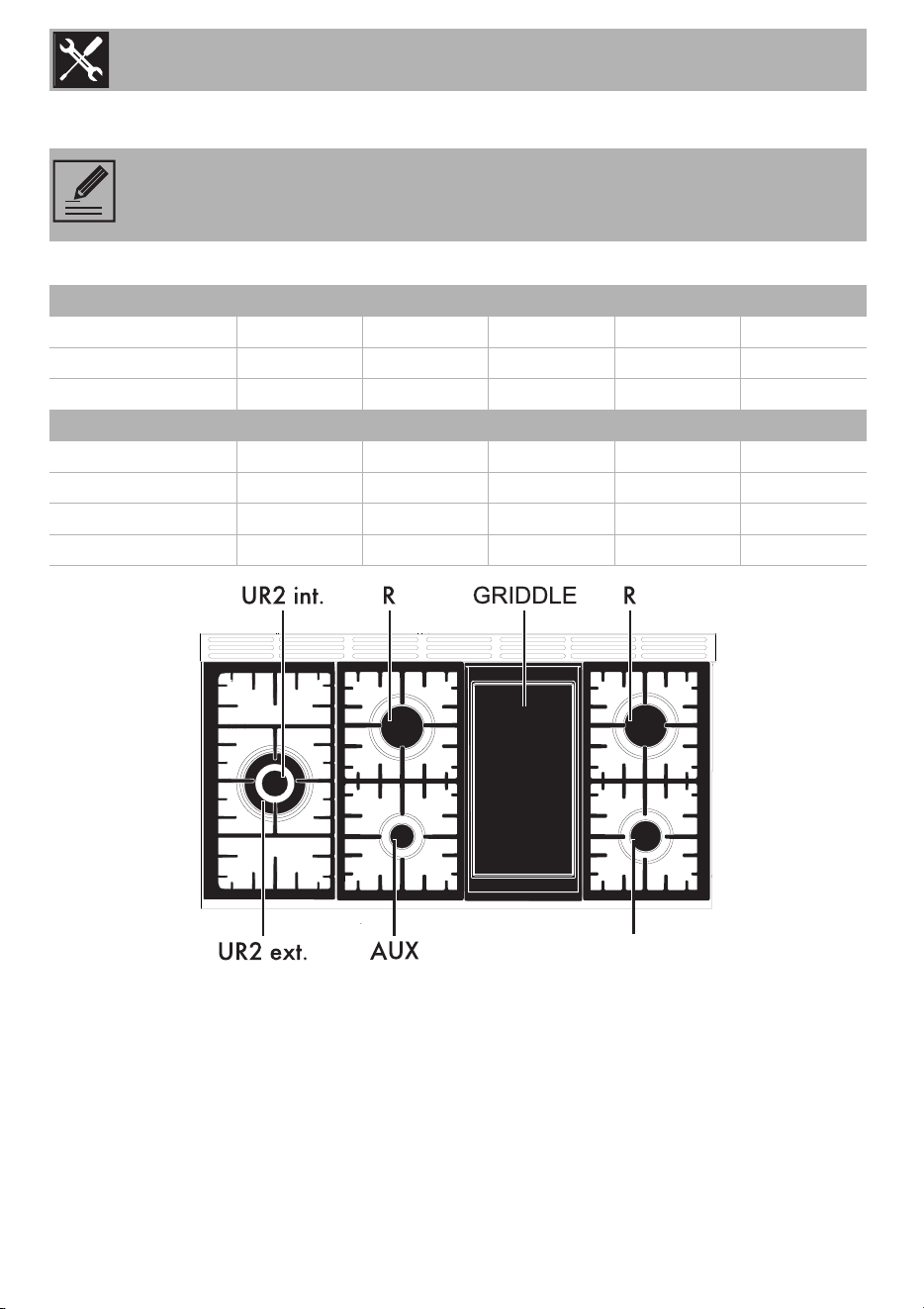
Natural Gas AUX SR R UR2 int. UR2 ext.
QT (BTU)
5000 8000 15000 3000 19000
Injector Ø (mm)
1.00 1.20 1.75 0.75 2.00
QR (BTU)
1000 1600 2500 1000 4200
LP AUX SR R UR2 int. UR2 ext.
QT (BTU)
4800 7700 12000 2500 15500
Injector Ø (mm)
0.65 0.80 1.02 0.48 1.15
QR (BTU)
1000 1600 2500 1000 4200
By-pass (mm)
0.30 0.39 0.45 0.30 0.63
SR
Installation
29
EN
• Connect the gas supply line to the unit
pressure regulator using a 1/2” flex gas
line connector between the manual shut-
off valve and the pressure regulator. A
metal flex line or fixed metal pipe must
be used to connect the gas to the
appliance. If a metal gas line cannot be
used, consult your local certified
electrician or local electric codes for
proper grounding.
• Check the supply line connections for
leaks using a soap solution or non-
corrosive leak detection fluid. Do not use
a flame of any sort.
1. Turn on gas.
2. Apply a soap solution or non-corrosive
leak detection fluid to all joints and
fittings in the gas connection between the
shut-off valve and the cooktop. Include
gas fittings and joints in the cooktop if
connections may have been disturbed
during installation. Bubbles appearing
around fittings and connections indicate
a leak.
3. If you detect a leak, turn off the supply
line gas shut-off valve and tighten
connections.
4. Retest for leaks by turning the gas supply
line shutoff valve on. When the leak
check has been completed (no bubbles
appear), the test is complete.
5. Wipe off all residues of the soap solution
or detection fluid.
Important notes for Gas Connection
• The appliance and its individual gas
shutoff valve must be disconnected from
the gas supply piping system during
pressure testing of the system at test
pressures in excess of 1/2 psi (3.5kPa).
• The appliance must be isolated from the
gas supply piping system by turning off
its individual manual shut-off valve during
pressure testing of the gas supply piping
system at test pressures equal to or less
than 1/2 psi (3.5kPa).
Final operations
• Completely fill out the conversion label
(part no. 92849A078) and attach it to
the rear of the appliance. Do not cover
any other labels with the conversion
label.
• Over time, the gas taps may become
difficult to turn and jam. Clean them
internally and replace the lubrication
grease.
Assembling the backguard
WARNING
Install a gas shutoff valve near the
appliance. After installation, it must be
easily accessible in an emergency.
NOTE: Lubrication of the gas taps
should be performed by a
specialized technician.
The backguard provided is an
integral part of the product; it must
be fastened to the appliance prior
to installation.
Installation
30
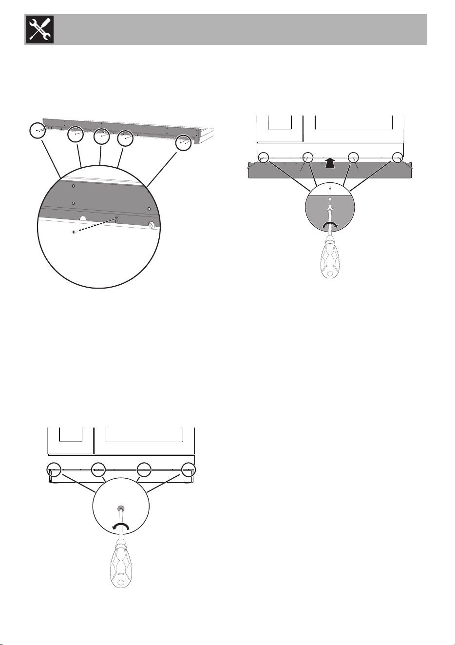
The backguard must always be positioned
and secured correctly on the appliance.
1. Position the backguard above the top,
taking care to align the holes.
2. Secure the backguard to the top by
tightening screws.
Installing the front skirting
The front skirting must always be positioned
and secured correctly on the appliance.
1. Use a screwdriver to remove the front
screws undreneath the storage
compartment.
2. Position the front kick plate at the bottom
of the appliance and align the holes
marked by a circle in the figure with the
corresponding ones on the appliance.
3. Fasten the front skirting to the appliance
using the previously removed screws.
Installing the side skirting
After installing the front skirting, the side
skirting can be fastened correctly to the
appliance.
1. Position the side skirting on the lower side
section of the appliance below the
storage compartment.
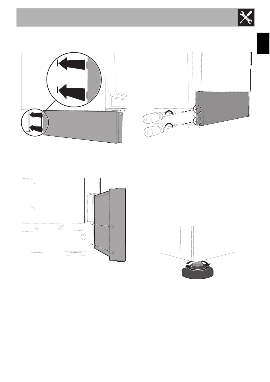
Installation
31
EN
2. Fit the tabs of side kick plate in the slots at
the ends of the front kick plate.
3. Line up the holes on the side skirting with
the rear holes on the base of the
appliance.
4. Secure the side kick plate with the
supplied screws.
5. Repeat the operations described above
for the other side skirting section.
Positioning and levelling the appliance
After making the electrical and/or gas
connections, properly level the appliance
on the floor to ensure better stability. Screw
or unscrew the bottom part of the foot until
the appliance is stable and level on the
floor.
2.1 For the installer
• The plug must remain accessible after the
installation is complete. Do not kink or
trap the mains connection cable.
• The appliance must be fitted according
to the installation diagrams.
• Do not attempt to turn or stress the
threaded elbow on the manifold. You risk
damage to this part of the appliance

Installation
32
which may void the manufacturer’s
warranty.
• Before leaving check all connections for
gas leaks with soap and water. DO
NOT use a naked flame for detecting
leaks.
• Ignite all burners individually and
concurrently to ensure correct operation
of the gas valves, burner and ignition.
• Turn the gas knobs to the low position
and observe stability of the flame for
each burner individually and all together.
• In case the appliance fails to operate
correctly after all checks have been
carried out, refer to the Authorised
Assistance Centre in your area.
• When satisfied with the appliance,
please instruct the user on the correct
method of operation.