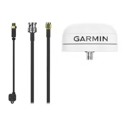
GPS 24XD HVS NMEA
®
0183
INSTALLATION INSTRUCTIONS
Important Safety Information
CAUTION
To avoid possible personal injury, always wear safety goggles, ear protection, and a dust mask when drilling,
cutting, or sanding.
NOTICE
When drilling or cutting, always check what is on the opposite side of the surface to avoid damaging the vessel.
For the best performance and to avoid damage to your boat, read all installation instructions before proceeding.
Install the device per these instructions. Use the appropriate fasteners, tools, and mounts listed, which are
available at most marine dealers.
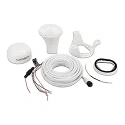
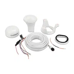
The Garmin
®
GPS 24xd HVS (NMEA 0183) high-sensitivity GPS antenna provides position information over
NMEA 0183. The GPS 24xd can be connected to a Garmin chartplotter or another NMEA 0183 compliant device.
For more information, go to garmin.com.
Tools Needed
• Drill
• 3.2 mm (1/8 in.) drill bit
• 19 mm (3/4 in.) drill bit for a pole-mount cable-hole
• 25 mm (1 in.) hole saw for a surface-mount cable-hole
• Countersink bit for mounting on fiberglass
• Screws for under-deck mounting
• Screwdriver, appropriate for the screw type
• Marine sealant (optional)
• Solder and shrink wrap for all wiring connections when limiting the antenna to 1Hz (Limiting the Antenna
Update Rate, page13).
TA-2020/6796
GUID-04C0F16F-F9A7-4EAC-96FC-C8DF7618E2D8 v5January 2024
Mounting the Antenna
Antenna Mounting Considerations
CAUTION
Do not install or store the antenna near strong magnets, including speakers. A strong magnetic field can
damage the antenna.
You can mount the antenna on a flat surface or attach it to a standard 1in. OD, 14threads per inch,
pipe-threaded pole (not included). You can route the cable outside of the pole or through the pole. For best
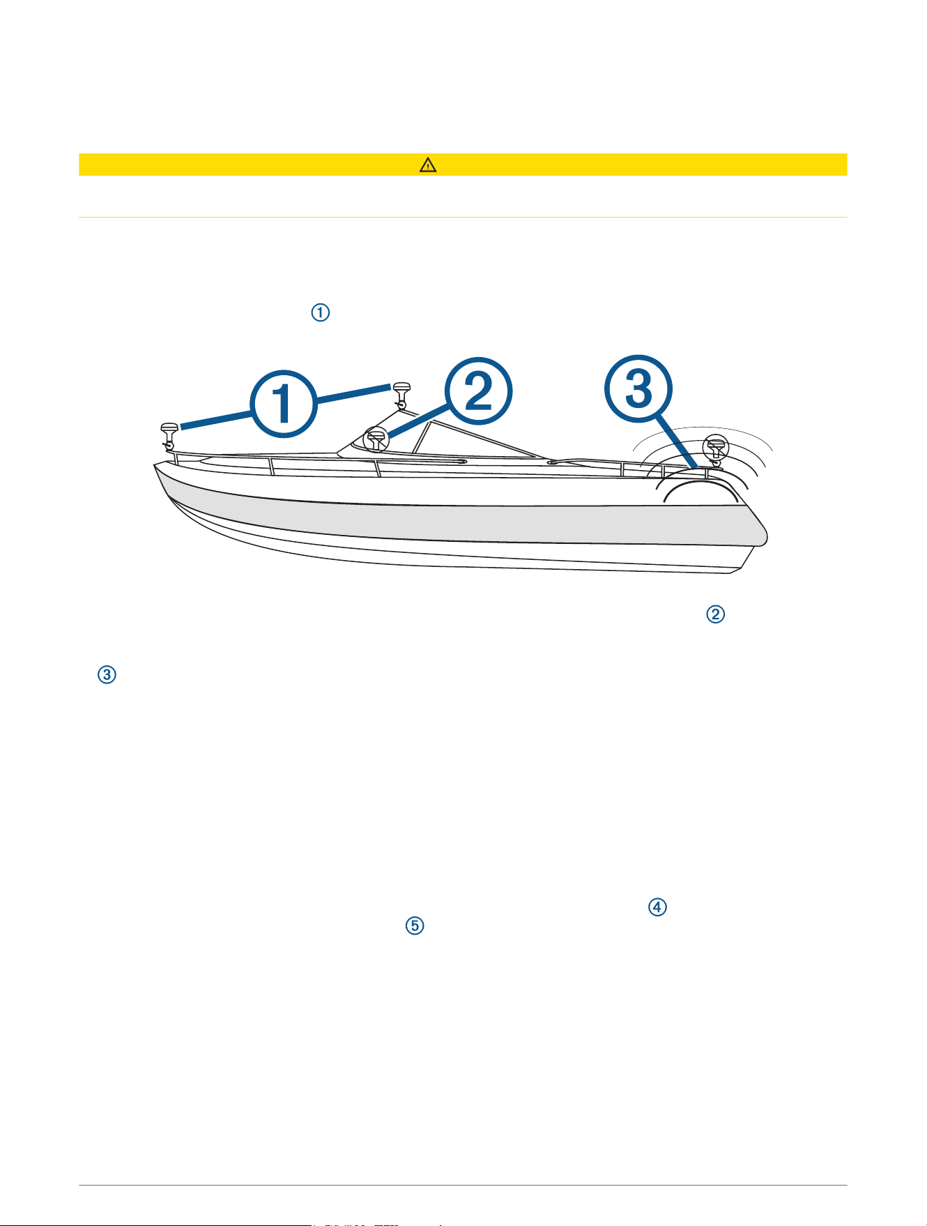
performance, consider these guidelines when selecting the antenna mounting location.
• To ensure the best reception, the antenna should be mounted in a location that has a clear, unobstructed
view of the sky in all directions .
• The antenna should not be mounted where it is shaded by the superstructure of the boat , a radome
antenna, or the mast.
• The antenna should not be mounted near the engine or other sources of Electromagnetic Interference (EMI)
.
• The antenna should not be mounted near known ferrous metal objects such as a toolbox or compass.
• A handheld compass should be used to test for magnetic interference in the area where the antenna is to be
mounted. Your boat, motors, and devices must be on during the test.
If the needle on the handheld compass moves when you hold it where you intend to mount the antenna,
magnetic interference is present. You must choose another location and test again.
• Mounting screws are provided with the antenna. If you use mounting hardware other than the provided
screws, the hardware must be made of quality stainless steel or brass material to avoid magnetic
interference with the antenna.
NOTE: Test all mounting hardware with a handheld compass to make sure no magnetic fields are present in
the hardware.
• If a radar is present, the antenna should be mounted above the path of the radar . If necessary, the antenna
may be mounted below the path of the radar .
2
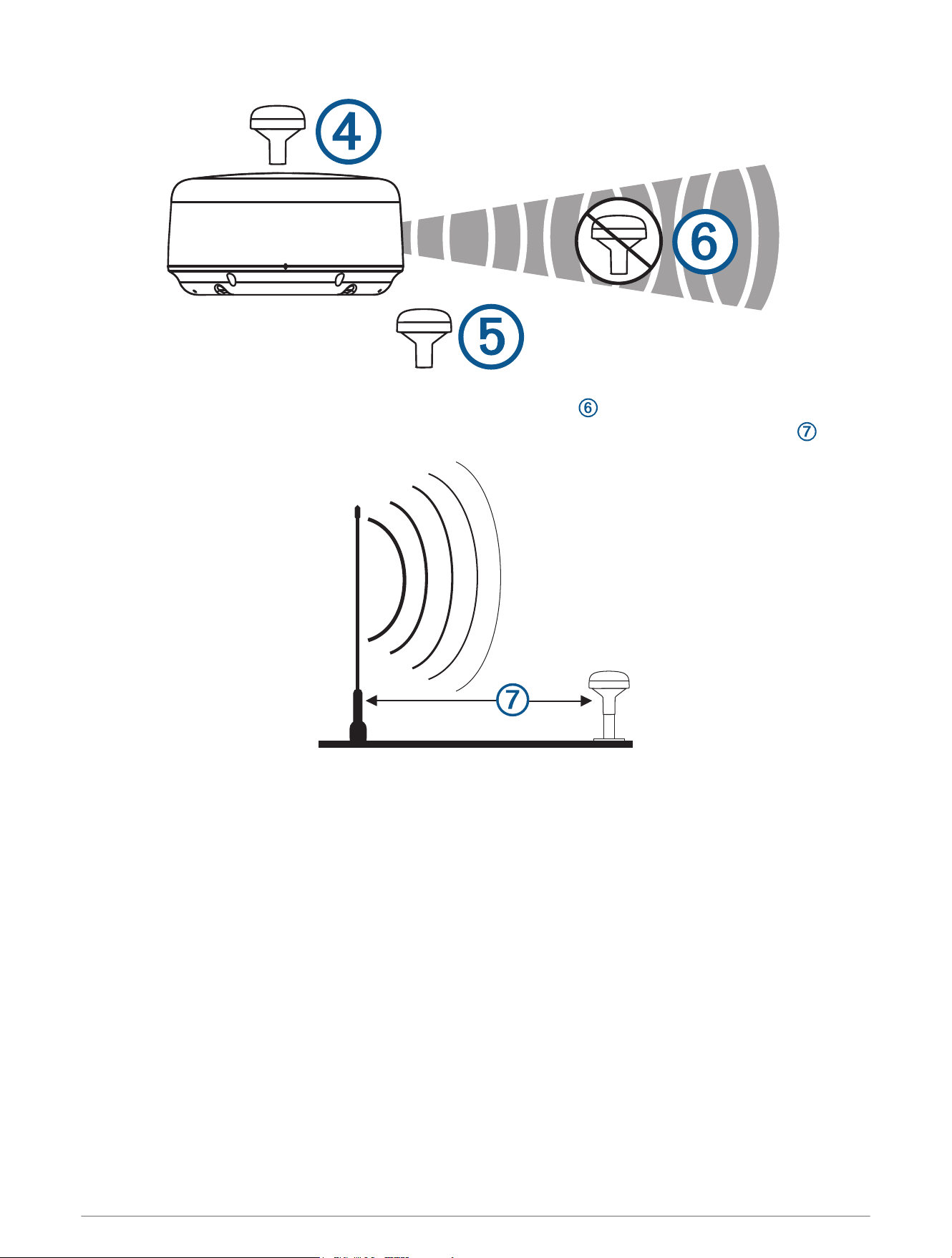
• The antenna should not be mounted directly in the path of the radar .
• The antenna should not be mounted within 1m (3ft.) of a VHF radio antenna or the path of a radar .
Testing the Mounting Location
1 Temporarily secure the antenna in the preferred mounting location and test it for correct operation.
2 If you experience interference with other electronics, move the antenna to a different location, and test it
again.
3 Repeat steps 1–2 until you observe full or acceptable signal strength.
4 Permanently mount the antenna.
3
Surface Mounting the Antenna
NOTICE
If you are mounting the bracket on fiberglass with screws, it is recommended to use a countersink bit to drill a
clearance counterbore through only the top gel-coat layer. This will help to avoid cracking in the gel-coat layer
when the screws are tightened.
Before you permanently mount the antenna, you must test the mounting location for correct operation (Testing
the Mounting Location, page3).
1 Using the surface-mount bracket as your mounting template, mark the three pilot-hole locations and trace
the cable-hole in the center of the bracket.
2 Set the surface-mount bracket aside.
Do not drill through the bracket.
3 Use a 3.2mm (
1
/
8
in.) drill bit to drill the three pilot holes.
4 Use a 25mm (1in.) drill bit or hole saw to drill or cut the cable hole in the center.
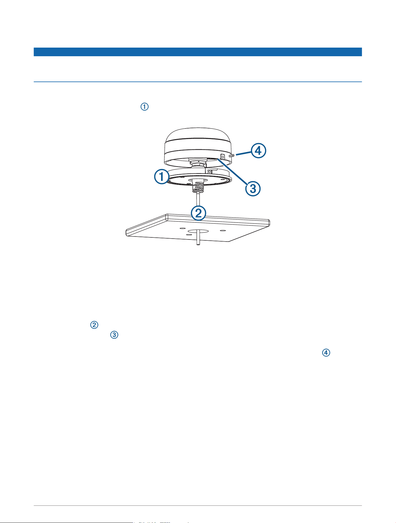
5 Use the included M4 screws and a Phillips screwdriver to secure the surface-mount bracket to the mounting
surface.
If the included M4 screws are too short, use M4 screws of appropriate length.
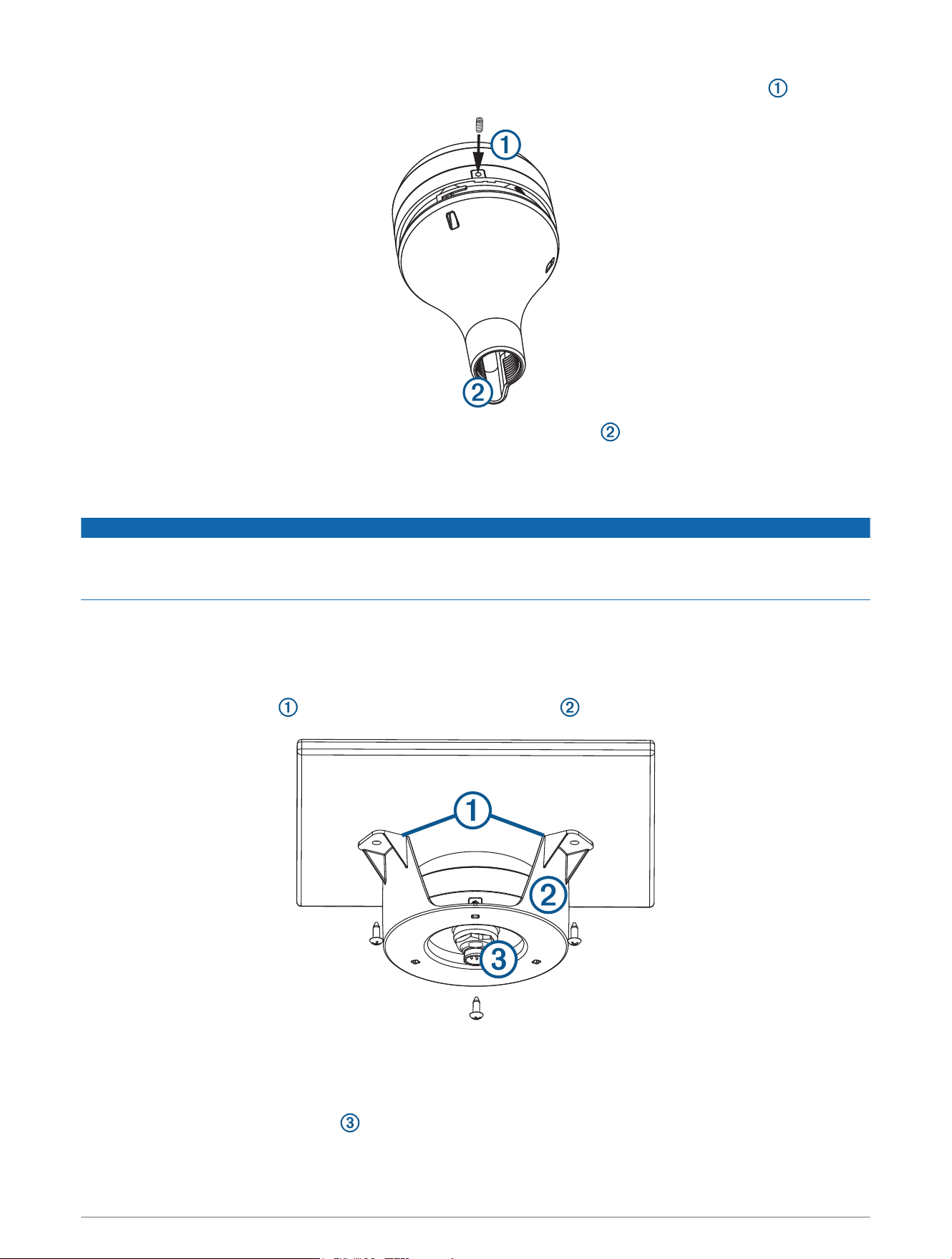
6 Route the cable through the center hole, and connect it to the antenna.
7 Verify the large gasket is in place on the bottom of the antenna, place the antenna on the surface-mount
bracket, and twist it clockwise to lock it in place.
8 Use the M3 set screw and a 1.5 mm hex wrench to secure the antenna to the mounting bracket .
9 Route the cable away from sources of electronic interference.
4
Mounting the Antenna on a Pole
Mounting the Antenna with the Cable Routed Outside the Pole
Before you permanently mount the antenna, you must test the mounting location for correct operation (Testing
the Mounting Location, page3).
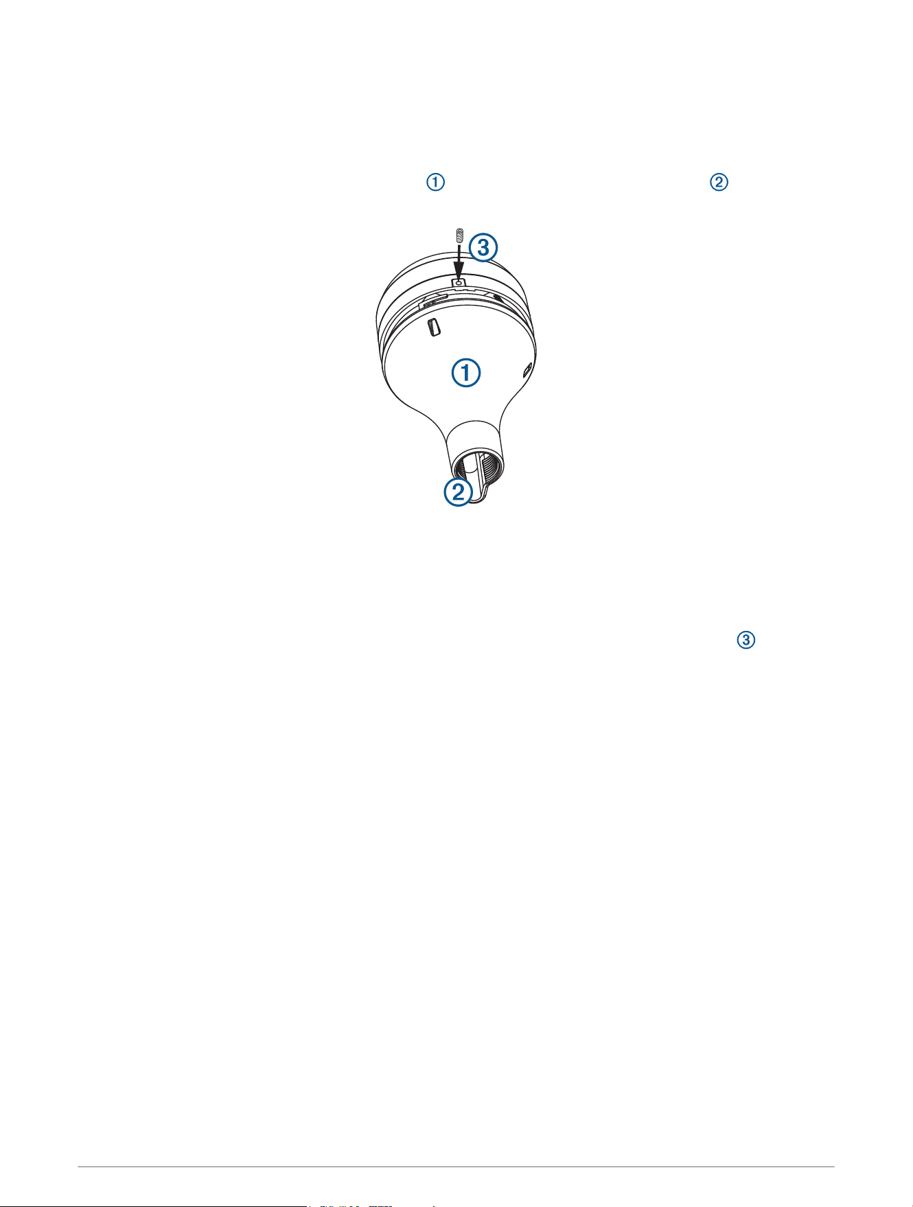
1 Route the cable through the pole-mount adapter , and place the cable in the vertical slot along the base
of the pole-mount adapter.
2 Screw the pole-mount adapter onto a standard 1in. OD, 14 threads per inch, pipe-threaded pole (not
included).
Do not overtighten the adapter on the pole.
3 Connect the cable to the antenna.
4 Place the antenna on the pole-mount adapter and twist it clockwise to lock it in place.
5 Use the included M3 set screw and a 1.5 mm hex wrench to secure the antenna to the adapter .
6 With the antenna installed on the pole mount, fill the remaining gap in the vertical cable slot with a marine
sealant (optional).
7 Attach the pole to the boat if it is not already attached.
8 Route the cable away from sources of electronic interference.
Mounting the Antenna with the Cable Routed Through the Pole
Before you permanently mount the antenna, you must test the mounting location for correct operation (Testing
the Mounting Location, page3).
1 Position a standard 1in. OD, 14 threads per inch, pipe-threaded pole (not included) in the selected location,
and mark the approximate center of the pole.
2 Use a 19mm (
3
/
4
in.) drill bit to drill a hole for the cable to pass through.
3 Fasten the pole to the boat.
4 Thread the pole-mount adapter onto the pole.
Do not overtighten the adapter.
5 Route the cable through the pole and connect it to the antenna.
6 Place the antenna on the pole-mount adapter and twist it clockwise to lock it in place.
5
7 Use the included M3 set screw and a 1.5 mm hex wrench to secure the antenna to the adapter .
8 With the antenna installed on the pole mount, fill the vertical cable slot with a marine sealant (optional).
9 Route the cable away from sources of electronic interference.
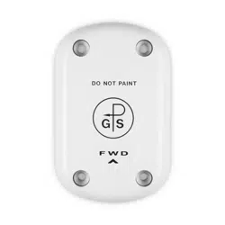
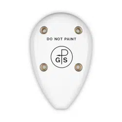
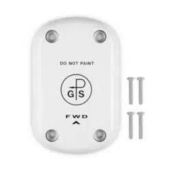
Mounting the Antenna Under the Deck
NOTICE
Before attaching the under-deck mounting bracket to the surface, verify the included screws will not penetrate
the surface. If the included screws are too long, you must purchase surface-appropriate screws to complete the
installation.
Before you permanently mount the antenna, you must test the mounting location for correct operation (Testing
the Mounting Location, page3).
Because the antenna cannot acquire signals through metal, it must be mounted under a fiberglass surface only.
The under-deck mounting kit is supplied with the white antenna models only.
1 Place the adhesive pads on the under-deck mounting bracket .
2 Place the antenna in the under-deck mounting bracket.
3 Adhere the under-deck mounting bracket to the mounting surface.
4 Secure the under-deck mounting bracket to the mounting surface with screws.
5 Connect the cable to the antenna .
6 Route the cable away from sources of electronic interference.
6
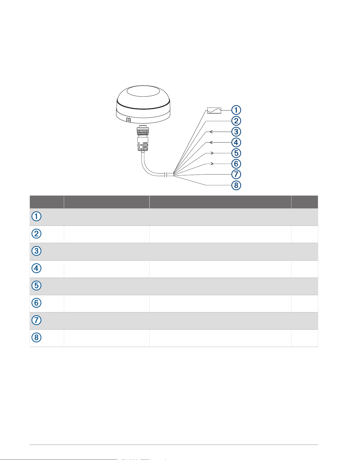
Connecting the Antenna
Power and NMEA 0183 Wiring
The antenna must be connected to power and to a NMEA 0183 compliant device. The diagrams show how to
correctly wire the antenna. You can connect up to three NMEA 0183 compliant devices to receive data from one
antenna.
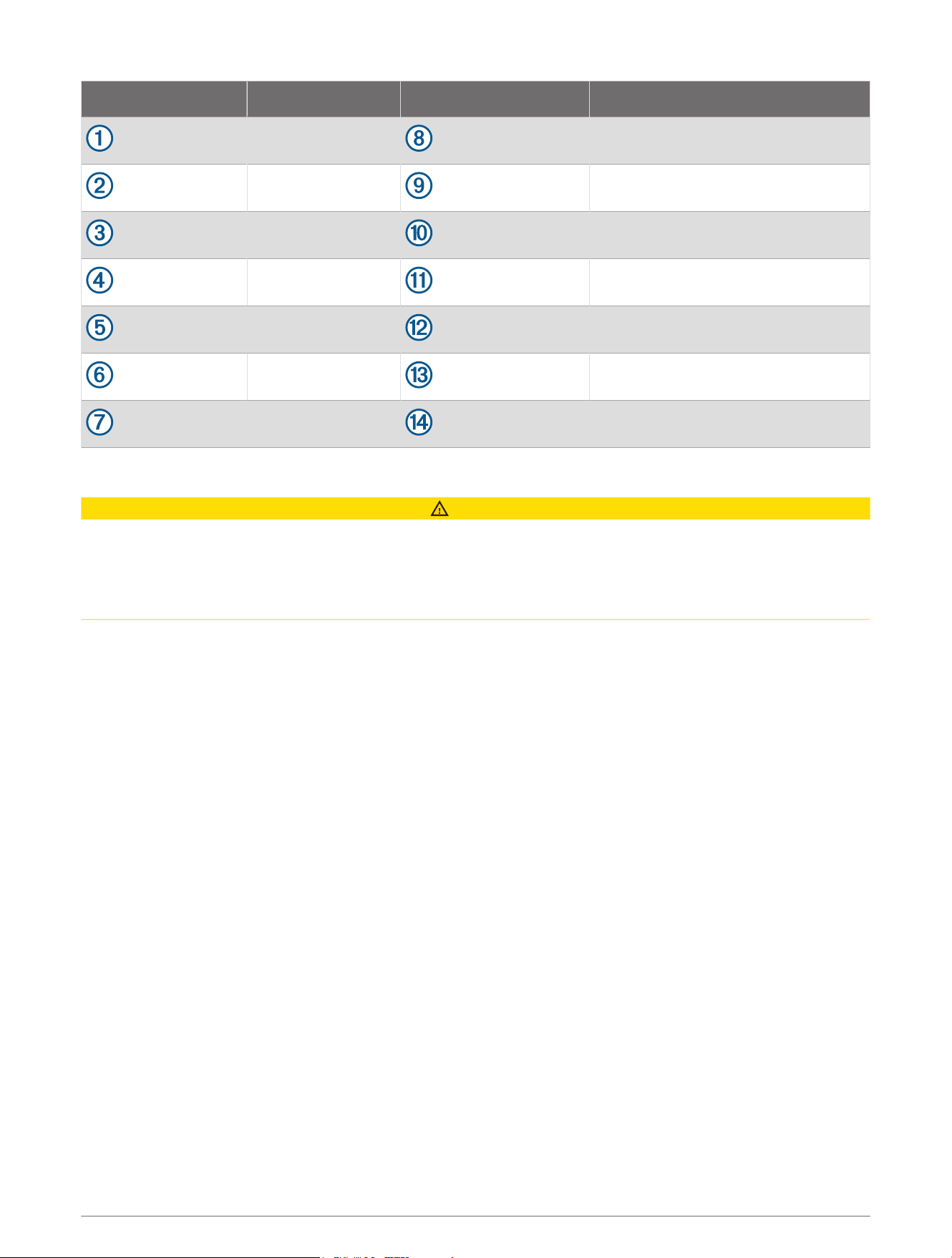
Wire Color Function Pin
Red Power (1A fuse) 3
Black Ground 2
White/orange Rx/B (In -) 7
White Rx/A (In +) 1
Gray Tx/A (Out +) 6
White/red Tx/B (Out -) 5
Orange Accessory on 4
Purple Pulse per second (PPS) 8
7
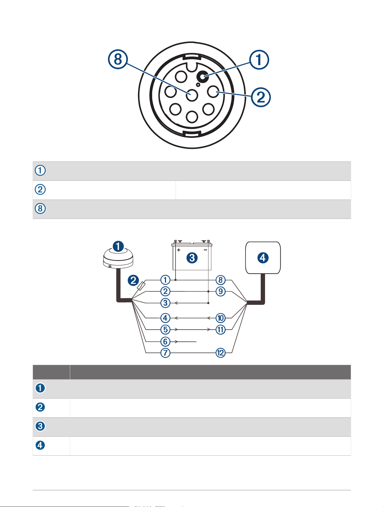
Pin 1
Pin 2
Pin 8
Connection from the Antenna to a Garmin Chartplotter (Single-Ended)
Item Description
Antenna
1A fuse
Power source
Garmin NMEA 0183 compatible chartplotter
8
GPS 24xd wire Color GPS 24xd wire function Chartplotter wire
Red Power (1 A fuse)
Black Ground
White/orange (ground) Rx/B (In -)
White Rx/A (In +)
Gray Tx/A (Out +)
White/red (unconnected) Tx/B (Out -)
Orange Accessory on
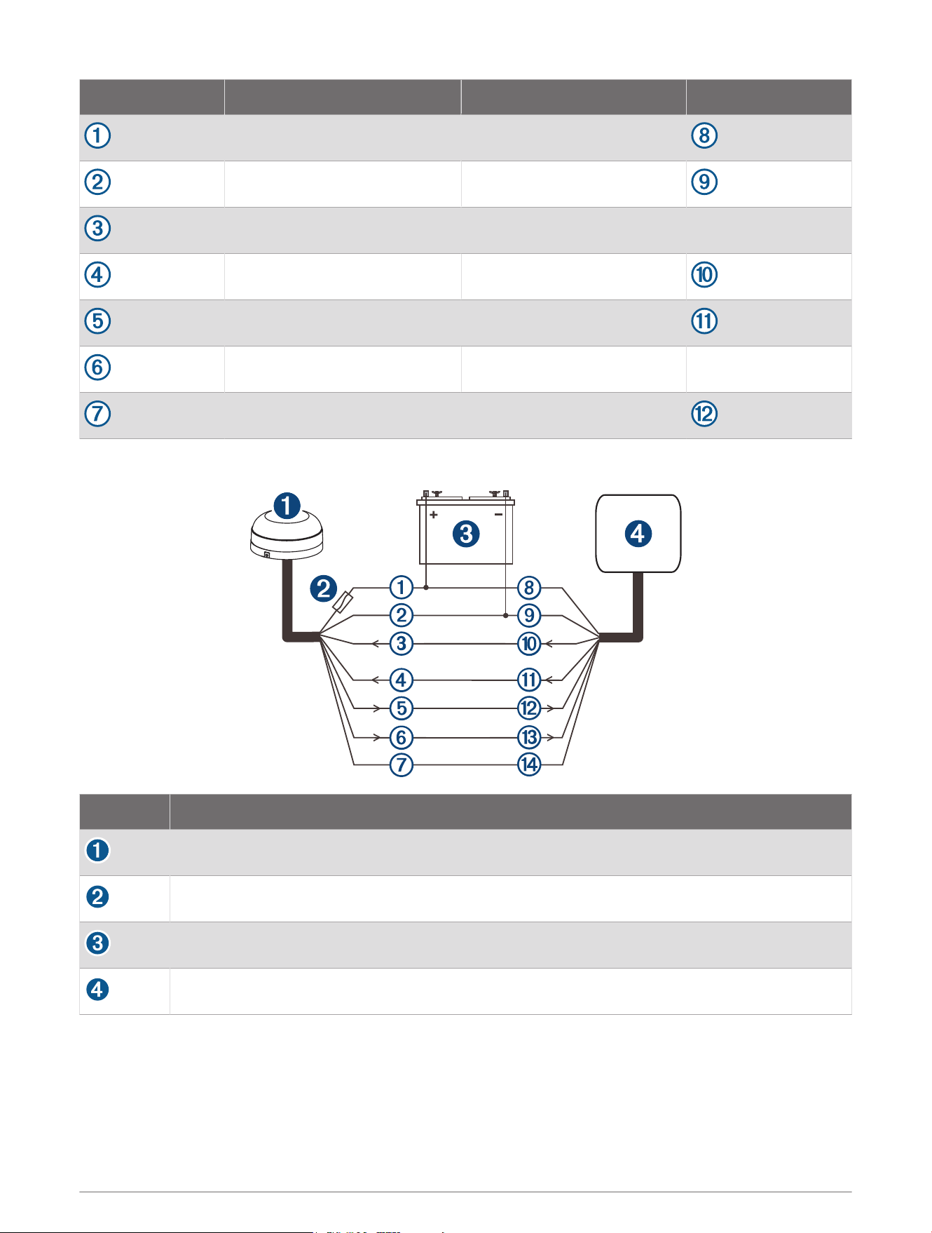
NMEA 0183 Wiring for Two-Way Communication
Item Description
Antenna
1Amp fuse
Power source
Garmin NMEA 0183 compatible chartplotter
9
GPS 24xd wire Color Chartplotter wire Chartplotter wire function
Red Power (+)
Black Ground (-)
White/orange Tx/B (Out -)
White Tx/A (Out +)
Gray Rx/A (In +)
White/red Rx/B (In -)
Orange Accessory on
NMEA 0183 Connection Exceptions
CAUTION
The orange accessory on wire is used when connecting the antenna to a Garmin chartplotter, or other NMEA
0183 device that has a defined accessory signal wire. If you are connecting the antenna to a device that
does not have an accessory signal wire, connect the orange wire from the antenna to ground and connect the
antenna power wire to the ignition or install an in-line switch. The antenna will drain the battery of the boat if it is
not switched.
• If your NMEA 0183 compliant device has only one receiving wire (Rx), connect it to the gray wire (Tx/A (Out
+)) from the antenna, and leave the white/red wire (Tx/B (Out -)) from the antenna unconnected.
• If your NMEA 0183 compliant device has only one transmitting wire (Tx), connect it to the white wire (Rx/A (In
+)) from the antenna, and connect the white/orange wire (Rx/B (In -)) from the antenna to ground.
Heading Calibration
After installation is complete, you must calibrate the heading and perform the auto heading alignment to receive
magnetic heading data.
Performing Basic Calibration
You must be able to view heading data from the antenna on a connected chartplotter or marine instrument
before you can perform basic calibration. If you cannot view heading data on your connected display, check the
power connections and the display's NMEA 0183 settings.
When performing basic calibration, you first calibrate the compass and then align the heading in one continuous
procedure.
NOTE: The boat must be able to reach a cruising speed of at least 6.4km/h (4mph) to perform the heading
alignment.
1 Drive the boat to a location with calm, open water.
2 Set the display to view heading data from the connected antenna.
NOTE: You must not use GPS Course Over Ground (COG) to perform basic calibration.
3 Disconnect power from the antenna.
4 Wait while the boat becomes level and stationary.
10
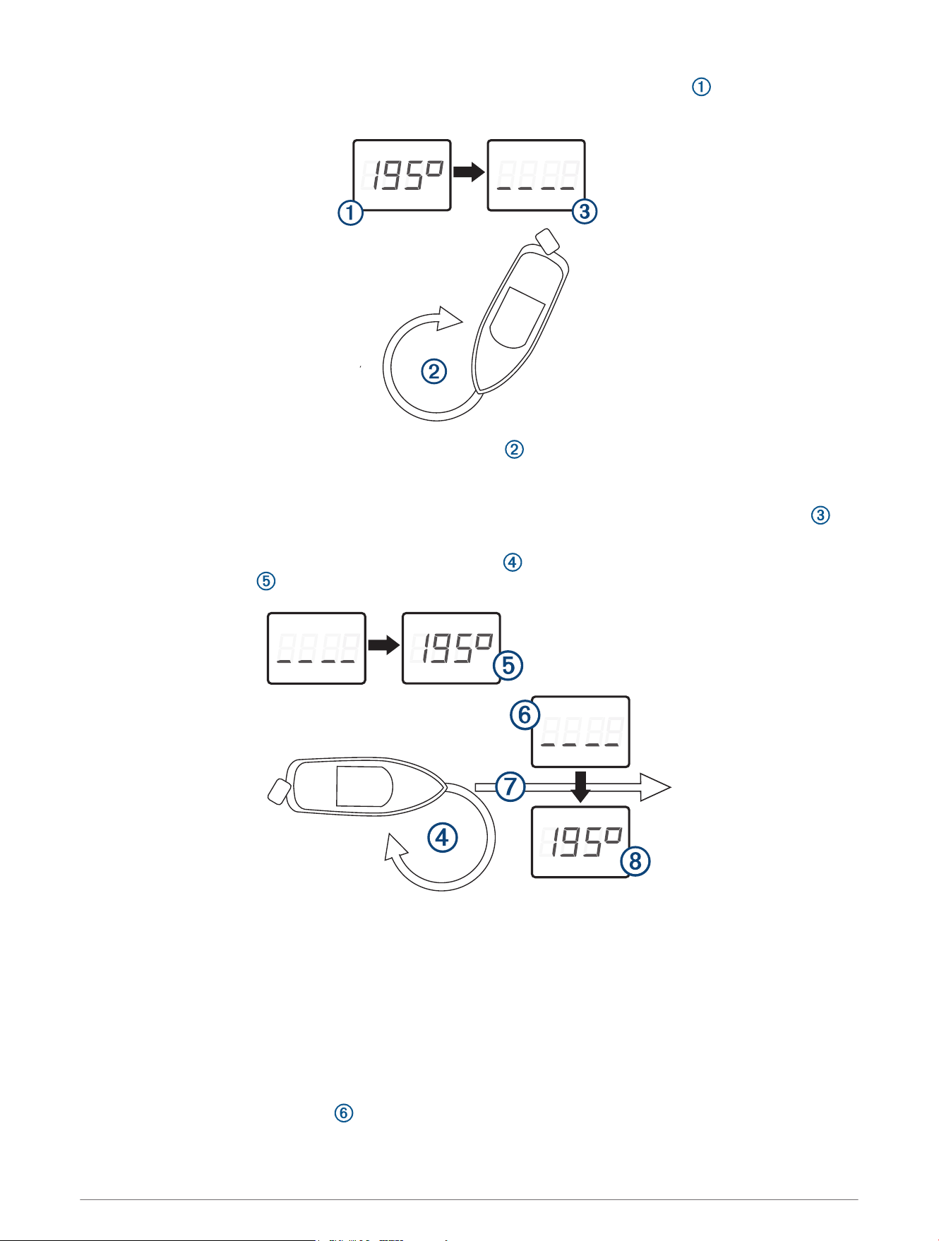
5 Turn on power to the antenna, and wait until the heading data appears on the display .
NOTE: If you are performing the first basic calibration after a factory reset, the heading is blank.
6 Within three minutes, complete two full, slow, tight circles , taking care to keep the boat as steady and
level as possible.
The boat should not list during calibration.
When the antenna is prepared to calibrate the compass, the heading data disappears from the display .
You may receive an error message that the heading was lost. You can ignore this message.
7 Continue turning in the same direction at the same speed for approximately 1
1
/
2
rotations until the
heading data appears .
When the heading data appears, the compass has been calibrated successfully, and you can align the
heading (optional).
8 Select an option.
• If you want to align the heading to match the front of the boat, proceed to the next step.
• If you do not want to align the heading, stop turning and wait, keeping the boat stationary. Over the next
two minutes the heading data should disappear and then reappear. When the heading data reappears, the
compass should be calibrated and no heading offset should be applied.
NOTE: If an unwanted heading offset is applied, repeat the calibration procedure.
9 Continue turning in the same direction at the same speed for approximately ten seconds, until the heading
data disappears from the display .
11
10 When it is safe, straighten the boat and drive in a straight line at cruising speed (must be at least
6.4km/h (4mph)) until the heading data appears .
When the heading appears, the compass has been calibrated, and the heading has been aligned on the
antenna.
11 Test the results of the calibration, and repeat this procedure if necessary.
Disabling the Magnetic Heading Data
If you cannot mount the antenna in an ideal location for magnetic heading and GPS performance, you can
disable the magnetic heading data.
1 Drive the boat to a location with calm, open water.
2 Set the display to view heading data from the antenna.
3 Disconnect power from the antenna.
4 Wait while the boat becomes level and stationary.
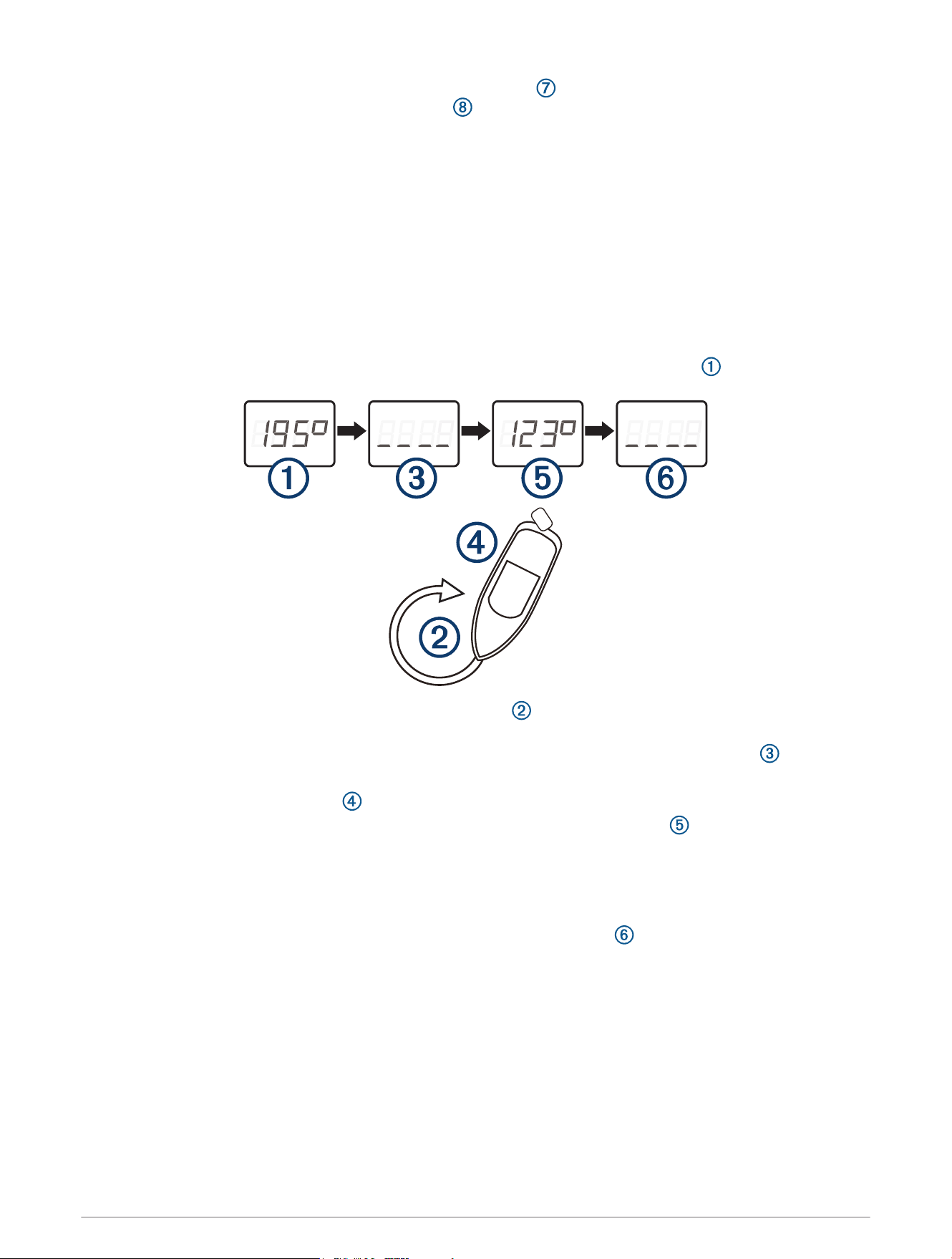
5 Turn on power to the antenna, and wait until the heading data appears on the display .
6 Within three minutes, complete two full, slow, tight circles , taking care to keep the boat as steady and
level as possible.
Heading data disappears to indicate that the antenna has detected the start of the procedure .
You may receive an error message that the heading was lost. You can ignore this message.
7 Bring the boat to a complete stop , and remain stationary for two minutes.
After two minutes, the heading data reappears with a fixed value of 123 degrees to indicate heading will
be disabled on the next power cycle.
NOTE: If the magnetic heading is displayed, the fixed value is 123 degrees. If the true heading is displayed,
the fixed value may deviate because of corrections from magnetic variation.
8 Disconnect power from the antenna.
9 Turn on power to the antenna, and verify that heading has been disabled .
12

Limiting the Antenna Update Rate
By default, the antenna outputs position data updates 10 times per second using serial communications rate of
38400 bps. By installing the included resistor cable, the antenna can be limited to output position updates once
per second using serial communications rate of 4800 bps.
1 Mount the antenna according to these instructions (Mounting the Antenna, page2).
2 If necessary, cut the cable to the appropriate length for the installation.
3 Solder the included Update Rate Select cable to the orange Accessory on wire.
4 Use the heat-shrink tubing around the soldered connections.
5 If you have not connected the antenna already, connect the power and data cable (NMEA 0183 Wiring for
Two-Way Communication, page9).
Cleaning the Outer Casing
NOTICE
Avoid chemical cleaners and solvents that can damage plastic components.
1 Clean the outer casing of the device using a cloth dampened with a mild detergent solution.
2 Wipe the device dry.
Appendix
Software Update
You must update the Garmin chartplotter software when you install this device. For instructions on updating the
software, see your chartplotter owner's manual at support.garmin.com.
Specifications
Dimensions (diameter x height) 3
19
/
32
× 1
15
/
16
in. (91.6 × 49.5mm)
Weight 201g (7.1oz.)
Cable length 30ft. (9.14m)
Temperature range
White model: From -30° to 80°C (-22° to 176°F)
Black model: From -30° to 65°C (-22° to 149°F)
Case material Fully gasketed, high-impact plastic alloy
Water rating IEC 60529 IPX6 and IPX7
1
Compass-safe distance 12.7mm (0.5 in.)
Input voltage From 8 to 32Vdc
Max. input current 200mA @ 12Vdc
Typical input current 150mA @ 12Vdc
1
The device withstands incidental exposure to water of up to 1m for up to 30min, and is protected against powerful jets of water. For more information, go to
www.garmin.com/waterrating.
13

NMEA 0183 Information
Transmit
Sentence Description
GPGGA Global Positioning System Fix Data
GPGSA GNSS DOP and Active Satellites
GPGSV and GLGSV GNSS Satellites in View
GPRMC Recommended Minimum Specific GNSS Data
GPVTG Course Over Ground and Ground Speed
GPGLL Geographic Position (latitude and longitude)
GPGNS GNSS Fix Data
HCHDG Heading, Deviation and Variation
PGRME Estimated Error Information
PGRMF GPS Fix Data
PGRMM Map Datum
PGRMT Sensor Status Information
PGRMV Velocity Information
PGRMB DPGS Beacon Information
PGRMID Device ID Information
Receive
Sentence Description
PGRMI Sensor Initialization Information
PGRMC Sensor Configuration Information
PGRMC1 Additional Sensor Configuration Information
PGRMC2 Additional Sensor Configuration Information 2
PGRMO Output Sentence Enable/Disable
PGRMID Device ID information
PGRMT Device information control
Declaration of Conformity
Hereby, Garmin declares that this product is in compliance with the Directive 2014/53/EU. The full text of the EU
declaration of conformity is available at the following internet address: garmin.com/compliance.
UK Declaration of Conformity
Hereby, Garmin declares that this product is in compliance with the relevant statutory requirements. The full text
of the declaration of conformity is available at the following internet address: garmin.com/compliance.
14

Innovation, Science and Economic Development Canada Compliance
This device contains licence-exempt transmitter(s)/receiver(s) that comply with Innovation, Science and
Economic Development Canada's licence-exempt RSS(s). Operation is subject to the following two conditions:
(1) this device may not cause interference, and (2) this device must accept any interference, including
interference that may cause undesired operation of the device.
FCC Compliance
This device complies with part 15 of the FCC Rules. Operation is subject to the following two conditions: (1) this
device may not cause harmful interference, and (2) this device must accept any interference received, including
interference that may cause undesired operation.
This equipment has been tested and found to comply with the limits for a Class B digital device, pursuant
to part 15 of the FCC rules. These limits are designed to provide reasonable protection against harmful
interference in a residential installation. This equipment generates, uses, and can radiate radio frequency energy
and may cause harmful interference to radio communications if not installed and used in accordance with the
instructions. However, there is no guarantee that interference will not occur in a particular installation. If this
equipment does cause harmful interference to radio or television reception, which can be determined by turning
the equipment off and on, the user is encouraged to try to correct the interference by one of the following
measures:
• Reorient or relocate the receiving antenna.
• Increase the separation between the equipment and the receiver.
• Connect the equipment into an outlet on a circuit different from that to which the receiver is connected.
• Consult the dealer or an experienced radio/TV technician for help.
This product does not contain any user-serviceable parts. Repairs should only be made by an authorized Garmin
service center. Unauthorized repairs or modifications could result in permanent damage to the equipment, and
void your warranty and your authority to operate this device under Part 15 regulations.
Limited Warranty
The Garmin standard limited warranty applies to this accessory. For more information, go to garmin.com
/support/warranty.
Australian Purchases: Our goods come with guarantees that cannot be excluded under the Australian
Consumer Law. You are entitled to a replacement or refund for a major failure and for compensation for any
other reasonably foreseeable loss or damage. You are also entitled to have the goods repaired or replaced if the
goods fail to be of acceptable quality and the failure does not amount to a major failure. The benefits under our
Limited Warranty are in addition to other rights and remedies under applicable law in relation to the products.
Garmin Australasia, 30 Clay Place, Eastern Creek, NSW 2766, Australia. Phone: 1800 235 822.
15
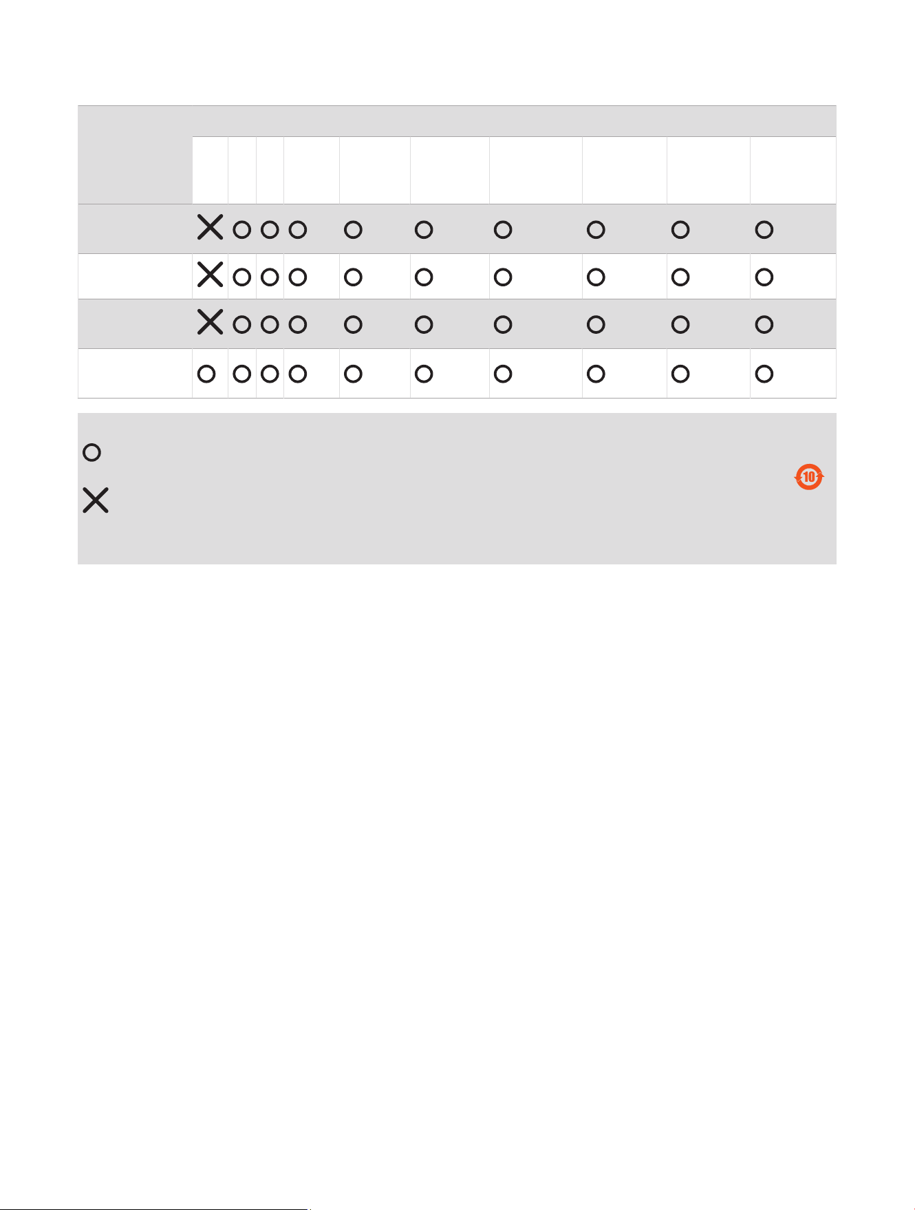
物質宣言
部件名称
有毒有害物质或元素
铅 汞 镉 六价铬 多溴联苯
多溴二苯
醚
邻苯二甲酸
二(2-乙基
己)酯
邻苯二甲
酸丁苄酯
邻苯二甲
酸二丁酯
邻苯二甲酸
二异丁酯
印刷电路板组
件
金属零件
电缆 电缆组件
连接器
塑料和橡胶零
件
本表格依据 SJ/T11364 的规定编制。
: 代表此种部件的所有均质材料中所含的该种有害物质均低于
(GB/T26572) 规定的限量
: 代表此种部件所用的均质材料中, 至少有一类材料其所含的有害物质高于
(GB/T26572) 规定的限量
* 该产品说明书应提供在环保使用期限和特殊标记的部分详细讲解产品的担保使用条件。
产品
連絡地址
製造銷售:台灣國際航電股份有限公司
聯絡地址:新北市汐止區樟樹二路 68 號
電 話:(02)2642-8999
客服專線:(02)2642-9199
© 2020 Garmin Ltd. or its subsidiaries
Garmin
®
and the Garmin logo are trademarks of Garmin Ltd. or its subsidiaries, registered in the USA and other countries. These trademarks may not be used without the
express permission of Garmin.
NMEA
®
is a registered trademark of the National Marine Electronics Association.
Garmin Corporation
© 2020 Garmin Ltd. or its subsidiaries
support.garmin.com