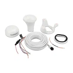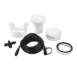
GPS 19X HVS NMEA
®
0183
INSTALLATION INSTRUCTIONS
Important Safety Information
CAUTION
To avoid possible personal injury, always wear safety goggles, ear protection, and a dust mask when drilling,
cutting, or sanding.
NOTICE
When drilling or cutting, always check what is on the opposite side of the surface to avoid damaging the vessel.
NOTE: When connecting this antenna with discontinued chartplotter models that do not display the GPS signal
properly, you must limit the update rate (Limiting the Antenna Update Rate, page 10).
For the best performance and to avoid damage to your boat, read all installation instructions before
proceeding. Install the device per these instructions. Use the appropriate fasteners, tools, and mounts listed,
which are available at most marine dealers.
For more information, go to support.garmin.com.
Tools Needed
• Drill
• 3.2 mm (1/8 in.) drill bit
• 19 mm (3/4 in.) drill bit for a pole-mount cable-hole
• 25 mm (1 in.) hole saw for a surface-mount cable-hole
• Countersink bit for mounting on fiberglass
• Screws for under-deck mounting
• Screwdriver, appropriate for the screw type
• Marine sealant (optional)
• Solder and shrink wrap for all wiring connections when limiting the antenna to 1 Hz (Limiting the Antenna
Update Rate, page 10).
TA-2013/784
GUID-89C91624-E41A-4D11-B9D2-80B76A5472F8 v2June 2021
Mounting the Antenna
Antenna Mounting Considerations
CAUTION
Do not install or store the antenna near strong magnets, including speakers. A strong magnetic field can
damage the antenna.
You can mount the antenna on a flat surface or attach it to a standard 1 in. OD, 14 threads per inch, pipe-
threaded pole (not included). You can route the cable outside of the pole or through the pole. For best
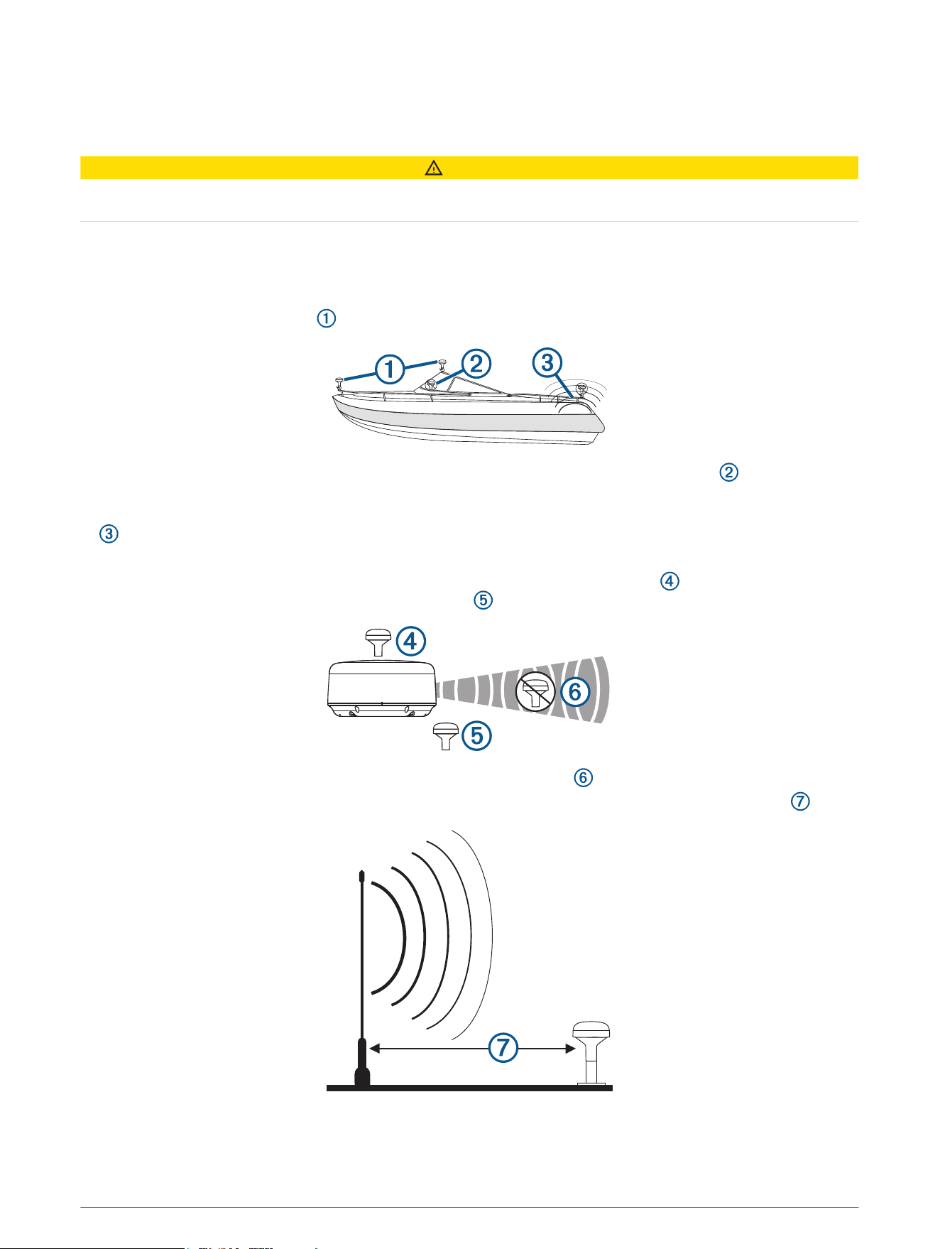
performance, consider these guidelines when selecting the antenna mounting location.
• To ensure the best reception, the antenna should be mounted in a location that has a clear, unobstructed
view of the sky in all directions .
• The antenna should not be mounted where it is shaded by the superstructure of the boat , a radome
antenna, or the mast.
• The antenna should not be mounted near the engine or other sources of Electromagnetic Interference (EMI)
.
• The antenna should not be mounted near known ferrous metal objects such as a toolbox or compass.
• If a radar is present, the antenna should be mounted above the path of the radar . If necessary, the
antenna may be mounted below the path of the radar .
• The antenna should not be mounted directly in the path of the radar .
• The antenna should not be mounted within 1 m (3 ft.) of a VHF radio antenna or the path of a radar .
2
Testing the Mounting Location
1 Temporarily secure the antenna in the preferred mounting location and test it for correct operation.
2 If you experience interference with other electronics, move the antenna to a different location, and test it
again.
3 Repeat steps 1–2 until you observe full or acceptable signal strength.
4 Permanently mount the antenna.
Surface Mounting the Antenna
NOTICE
If you are mounting the bracket on fiberglass with screws, it is recommended to use a countersink bit to drill a
clearance counterbore through only the top gel-coat layer. This will help to avoid cracking in the gel-coat layer
when the screws are tightened.
Before you permanently mount the antenna, you must test the mounting location for correct operation (Testing
the Mounting Location, page 3).
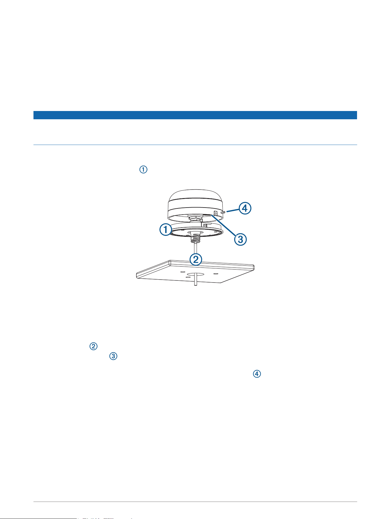
1 Using the surface-mount bracket as your mounting template, mark the three pilot-hole locations and
trace the cable-hole in the center of the bracket.
2 Set the surface-mount bracket aside.
Do not drill through the bracket.
3 Drill the three 3.2 mm (
1
/
8
in.) pilot holes.
4 Drill the 25 mm (1 in.) cable hole in the center.
5 Use the included M4 screws to secure the surface-mount bracket to the mounting surface.
6 Route the cable through the center hole, and connect it to the antenna.
7 Verify the large gasket is in place on the bottom of the antenna, place the antenna on the surface-mount
bracket, and twist it clockwise to lock it in place.
8 Secure the antenna to the mounting bracket with the included M3 screw .
9 Route the cable away from sources of electronic interference.
3
Mounting the Antenna on a Pole
Mounting the Antenna with the Cable Routed Outside the Pole
Before you permanently mount the antenna, you must test the mounting location for correct operation (Testing
the Mounting Location, page 3).
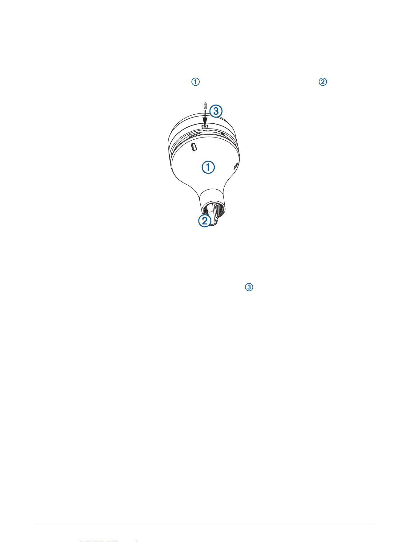
1 Route the cable through the pole-mount adapter , and place the cable in the vertical slot along the
base of the pole-mount adapter.
2 Screw the pole-mount adapter onto a standard 1 in. OD, 14 threads per inch, pipe-threaded pole (not
included).
Do not overtighten the adapter on the pole.
3 Connect the cable to the antenna.
4 Place the antenna on the pole-mount adapter and twist it clockwise to lock it in place.
5 Secure the antenna to the adapter with the included M3 set screw .
6 With the antenna installed on the pole mount, fill the remaining gap in the vertical cable slot with a marine
sealant (optional).
7 Attach the pole to the boat if it is not already attached.
8 Route the cable away from sources of electronic interference.
4
Mounting the Antenna with the Cable Routed Through the Pole
Before you permanently mount the antenna, you must test the mounting location for correct operation (Testing
the Mounting Location, page 3).
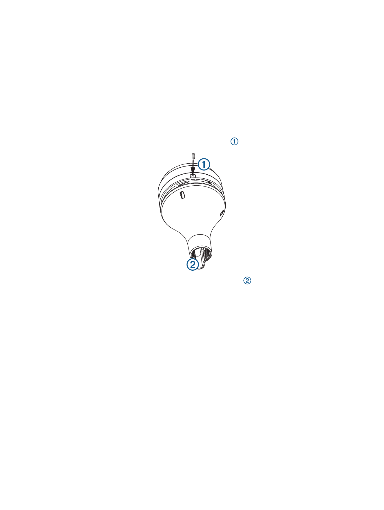
1 Position a standard 1 in. OD, 14 threads per inch, pipe-threaded pole (not included) in the selected location,
and mark the approximate center of the pole.
2 Drill a hole using a 19 mm (
3
/
4
in.) drill bit for the cable to pass through.
3 Fasten the pole to the boat.
4 Thread the pole-mount adapter onto the pole.
Do not overtighten the adapter.
5 Route the cable through the pole and connect it to the antenna.
6 Place the antenna on the pole-mount adapter and twist it clockwise to lock it in place.
7 Secure the antenna to the adapter with the included M3 set screw .
8 With the antenna installed on the pole mount, fill the vertical cable slot with a marine sealant (optional).
9 Route the cable away from sources of electronic interference.
5
Mounting the Antenna Under a Surface
NOTICE
Verify that the supplied screws will not penetrate the surface before you install the under-deck mounting
bracket. If the supplied screws are too long, use surface-appropriate screws instead.
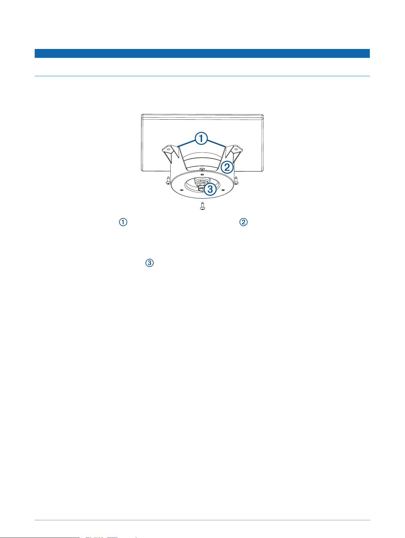
Because the antenna cannot acquire signals through metal, it must be mounted under a fiberglass surface only.
1 Determine and test the location under a fiberglass surface where you want to mount the antenna (Testing
the Mounting Location, page 3).
2 Place the adhesive pads on the under-deck mounting bracket .
3 Place the antenna in the under-deck mounting bracket.
4 Adhere the under-deck mounting bracket to the mounting surface.
5 Secure the under-deck mounting bracket to the mounting surface with screws.
6 Connect the cable to the antenna .
7 Route the cable away from sources of electronic interference.
6
Connecting the Antenna
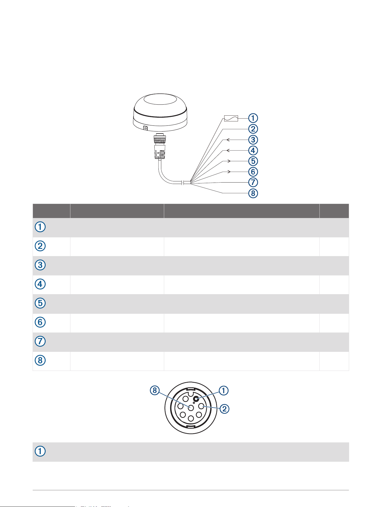
Power and NMEA 0183 Wiring
The antenna must be connected to power and to a NMEA 0183 compliant device. The diagrams show how to
correctly wire the antenna. You can connect up to three NMEA 0183 compliant devices to receive data from
one antenna.
Wire Color Function Pin
Red Power (1 A fuse) 3
Black Ground 2
White/orange Rx/B (In -) 7
White Rx/A (In +) 1
Gray Tx/A (Out +) 6
White/red Tx/B (Out -) 5
Orange Accessory on 4
Purple Pulse per second (PPS) 8
Pin 1
7
Pin 2
Pin 8
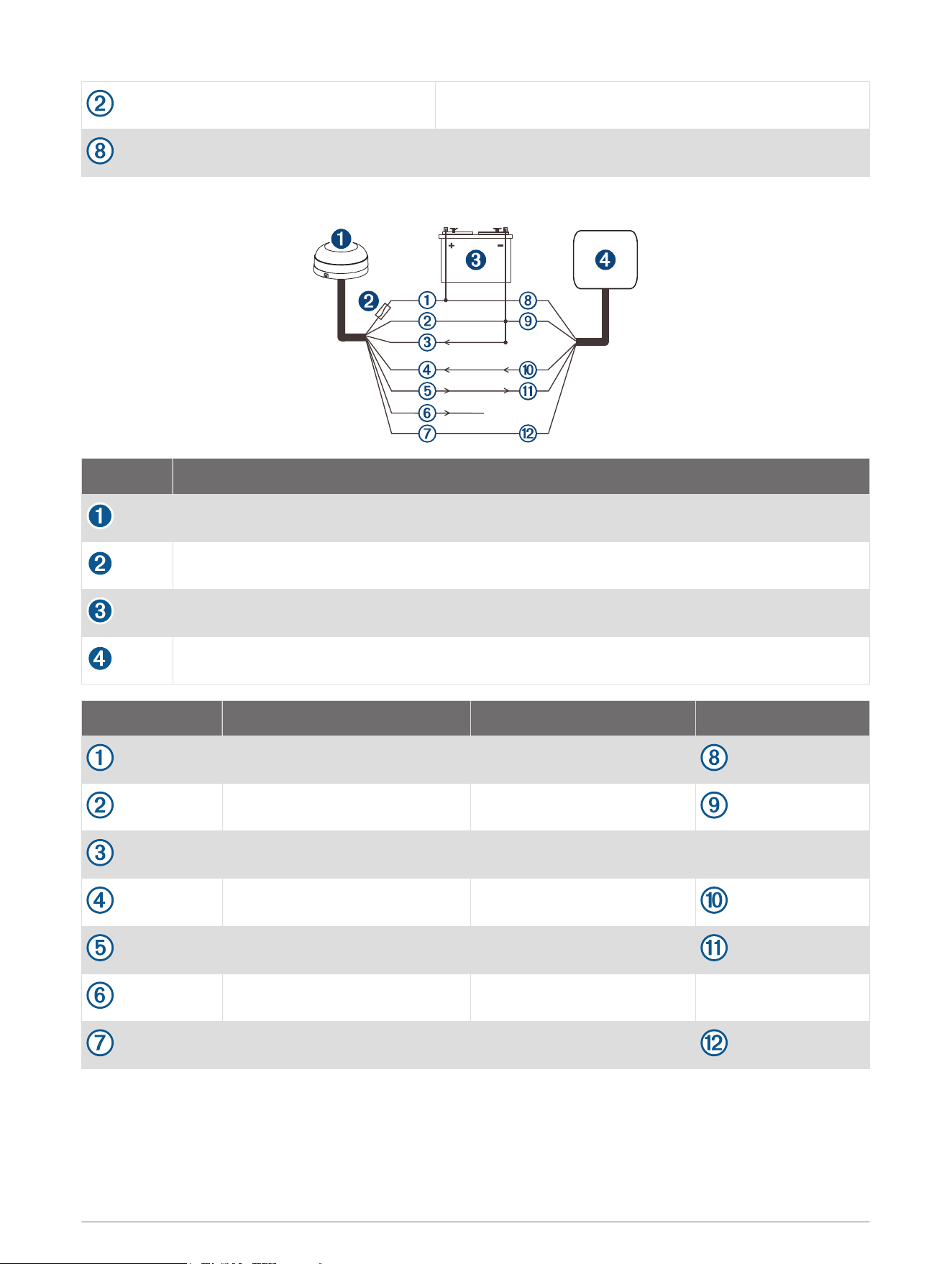
Connection from the Antenna to a Garmin Chartplotter (Single-Ended)
Item Description
Antenna
1 A fuse
Power source
Garmin
®
NMEA 0183 compatible chartplotter
GPS 19x wire Color GPS 19x wire function Chartplotter wire
Red Power (1 A fuse)
Black Ground
White/orange (ground) Rx/B (In -)
White Rx/A (In +)
Gray Tx/A (Out +)
White/red (unconnected) Tx/B (Out -)
Orange Accessory on
8
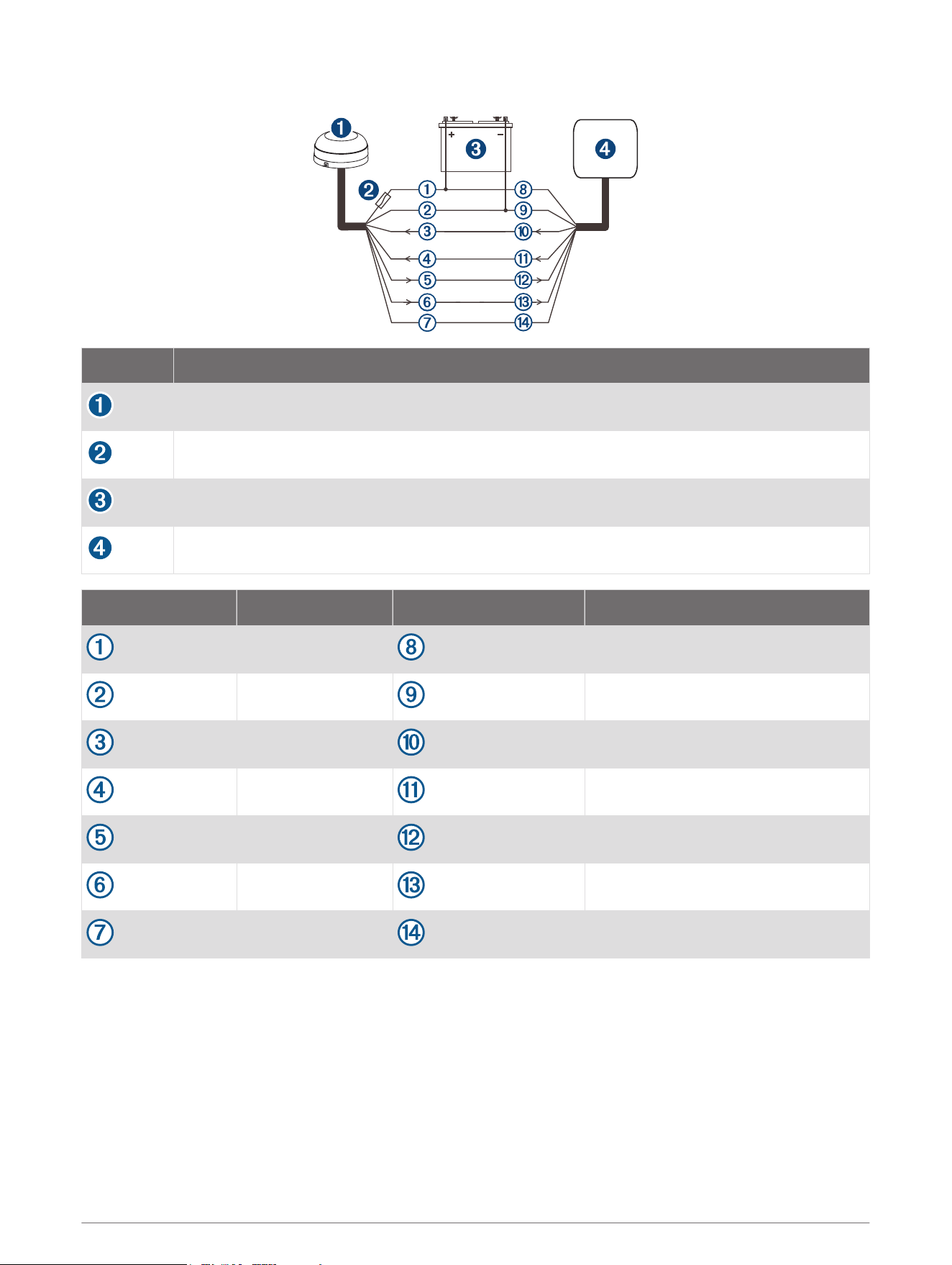
NMEA 0183 Wiring for Two-Way Communication
Item Description
Antenna
1 Amp fuse
Power source
Garmin NMEA 0183 compatible chartplotter
GPS 19x wire Color Chartplotter wire Chartplotter wire function
Red Power (+)
Black Ground (-)
White/orange Tx/B (Out -)
White Tx/A (Out +)
Gray Rx/A (In +)
White/red Rx/B (In -)
Orange Accessory on
9

NMEA 0183 Connection Exceptions
CAUTION
The orange accessory on wire is used when connecting the antenna to a Garmin chartplotter, or other NMEA
0183 device that has a defined accessory signal wire. If you are connecting the antenna to a device that does
not have an accessory signal wire, connect the orange wire from the antenna to ground and connect the
antenna power wire to the ignition or install an in-line switch. The antenna will drain the battery of the boat if it
is not switched.
• If your NMEA 0183 compliant device has only one receiving wire (Rx), connect it to the gray wire (Tx/A (Out
+)) from the antenna, and leave the white/red wire (Tx/B (Out -)) from the antenna unconnected.
• If your NMEA 0183 compliant device has only one transmitting wire (Tx), connect it to the white wire (Rx/A
(In +)) from the antenna, and connect the white/orange wire (Rx/B (In -)) from the antenna to ground.
Limiting the Antenna Update Rate
By default, the antenna outputs position data updates 10 times per second using serial communications rate of
38400 bps. By installing the included resistor cable, the antenna can be limited to output position updates once
per second using serial communications rate of 4800 bps.
1 Mount the antenna according to these instructions (Mounting the Antenna, page 2).
2 If necessary, cut the cable to the appropriate length for the installation.
3 Solder the included Update Rate Select cable to the orange Accessory on wire.
4 Use the heat-shrink tubing around the soldered connections.
5 If you have not connected the antenna already, connect the power and data cable (NMEA 0183 Wiring for
Two-Way Communication, page 9).
Cleaning the Outer Casing
NOTICE
Avoid chemical cleaners and solvents that can damage plastic components.
1 Clean the outer casing of the device using a cloth dampened with a mild detergent solution.
2 Wipe the device dry.
Appendix
Software Update
You must update the Garmin chartplotter software when you install this device. For instructions on updating
the software, see your chartplotter owner's manual at support.garmin.com.
10

Specifications
Dimensions (diameter x height) 91.6 × 49.5 mm ( 3
19
/
32
× 1
15
/
16
in.)
Weight 201 g (7.1 oz.)
Cable length 9.14 m (30 ft.)
Temperature range From -30° to 80°C (from -22° to 176°F)
Case material Fully gasketed, high-impact plastic alloy
Water rating IEC 60529 IPX7
1
Compass-safe distance 150 mm (5.9 in.)
Power input source 8 to 33 Vdc, unregulated
Input current 40 mA @ 12 Vdc
Battery Notice
NOTICE
Contact your local waste disposal department to dispose of the device/batteries in accordance with applicable
local laws and regulations.
Declaration of Conformity
Hereby, Garmin declares that this product is in compliance with the Directive 2014/53/EU. The full text of the
EU declaration of conformity is available at the following internet address: garmin.com/compliance.
UK Declaration of Conformity
Hereby, Garmin declares that this product is in compliance with the relevant statutory requirements. The full
text of the declaration of conformity is available at the following internet address: garmin.com/compliance.
Innovation, Science and Economic Development Canada Compliance
This device contains licence-exempt transmitter(s)/receiver(s) that comply with Innovation, Science and
Economic Development Canada's licence-exempt RSS(s). Operation is subject to the following two conditions:
(1) this device may not cause interference, and (2) this device must accept any interference, including
interference that may cause undesired operation of the device.
1
The device withstands incidental exposure to water of up to 1 m for up to 30 min. For more information, go to www.garmin.com/waterrating.
11

FCC Compliance
This device complies with part 15 of the FCC Rules. Operation is subject to the following two conditions: (1)
this device may not cause harmful interference, and (2) this device must accept any interference received,
including interference that may cause undesired operation.
This equipment has been tested and found to comply with the limits for a Class B digital device, pursuant to
part 15 of the FCC rules. These limits are designed to provide reasonable protection against harmful
interference in a residential installation. This equipment generates, uses, and can radiate radio frequency
energy and may cause harmful interference to radio communications if not installed and used in accordance
with the instructions. However, there is no guarantee that interference will not occur in a particular installation.
If this equipment does cause harmful interference to radio or television reception, which can be determined by
turning the equipment off and on, the user is encouraged to try to correct the interference by one of the
following measures:
• Reorient or relocate the receiving antenna.
• Increase the separation between the equipment and the receiver.
• Connect the equipment into an outlet on a circuit different from that to which the receiver is connected.
• Consult the dealer or an experienced radio/TV technician for help.
This product does not contain any user-serviceable parts. Repairs should only be made by an authorized
Garmin service center. Unauthorized repairs or modifications could result in permanent damage to the
equipment, and void your warranty and your authority to operate this device under Part 15 regulations.
Limited Warranty
The Garmin standard limited warranty applies to this accessory. For more information, go to www.garmin.com
/support/warranty.
© 2012 Garmin Ltd. or its subsidiaries
Garmin
®
and the Garmin logo are trademarks of Garmin Ltd. or its subsidiaries, registered in the USA and other countries. These trademarks may not be used without the
express permission of Garmin.
NMEA
®
is a registered trademark of the National Marine Electronics Association.
Garmin Corporation
© 2012 Garmin Ltd. or its subsidiaries
support.garmin.com