GXM
™
54
INSTALLATION INSTRUCTIONS
Important Safety Information
WARNING
The weather information provided through this product is subject to service interruptions and may contain
errors, inaccuracies, or outdated information, and consequently should not be relied upon exclusively. Always
use common sense while navigating, and check alternate weather information sources prior to making safety-
related decisions. You acknowledge and agree that you shall be solely responsible for use of the weather
information and all decisions taken with respect to navigating in weather. Garmin
®
will not be responsible for
any consequences of using SiriusXM
®
weather information.
When connecting the power cable, do not remove the in-line fuse holder. To prevent the possibility of injury or
product damage caused by fire or overheating, the appropriate fuse must be in place as indicated in the product
specifications. Connecting the power cable without the appropriate fuse in place voids the product warranty.
CAUTION
To avoid possible personal injury, always wear safety goggles, ear protection, and a dust mask when drilling,
cutting, or sanding.
NOTICE
When drilling or cutting, always check what is on the opposite side of the surface to avoid damaging the vessel.
Software Update
You must update the Garmin chartplotter software when you install this device. For instructions on updating the
software, see your chartplotter owner's manual at support.garmin.com.
Tools Needed
• Drill
• 3.2 mm (
1
/
8
in.) drill bit for pilot holes for surface mounting
• 25 mm (1 in.) hole saw or drill bit for surface-mount cable hole
• 19 mm (
3
/
4
in.) drill bit for pole-mount cable hole
• Countersink bit for surface mounting on fiberglass
• 1.5 mm hex wrench for included M3 screws
• Phillips screwdriver for included M4 screws
• M4 screws of appropriate length, if included M4 screws are too short
• Marine sealant (optional)
• Additional Garmin Marine Network components as needed
GUID-D57F5CDC-08A4-43F8-90A0-2A457D4A398E v4October 2022
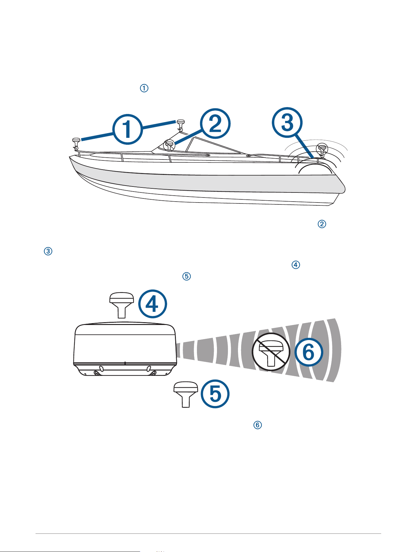
Antenna Mounting Considerations
You can mount the antenna on a flat surface or attach it to a standard 1in. OD, 14threads per inch,
pipe-threaded pole (not included). You can route the cable outside of the pole or through the pole. For best
performance, consider these guidelines when selecting the antenna mounting location.
• To ensure the best reception, the antenna should be mounted in a location that has a clear, unobstructed
view of the sky in all directions .
• The antenna should not be mounted where it is shaded by the superstructure of the boat , a radome
antenna, or the mast.
• The antenna should not be mounted near the engine or other sources of Electromagnetic Interference (EMI)
.
•
If a radar is present, the antenna should be mounted above the path of the radar . If necessary, the antenna
may be mounted below the path of the radar .
• The antenna should not be mounted directly in the path of the radar .
2
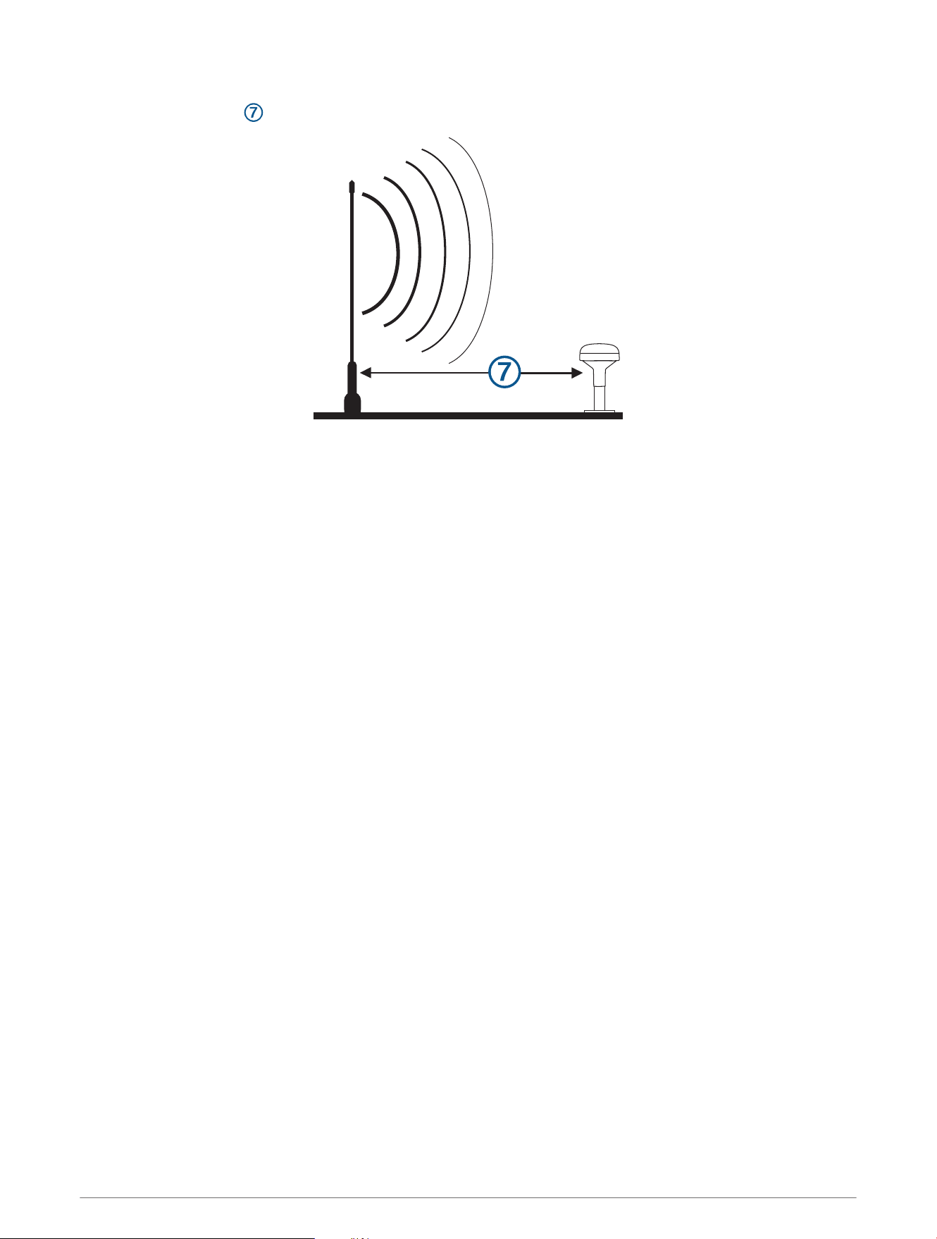
• The antenna should be mounted at least 1m (3ft.) away from (preferably above) the path of a radar beam or
a VHF radio antenna .
Testing the Mounting Location
1 Temporarily secure the antenna in the preferred mounting location and test it for correct operation.
2 If you experience interference with other electronics, move the antenna to a different location, and test it
again.
3 Repeat steps 1–2 until you observe full or acceptable signal strength.
4 Permanently mount the antenna.
3
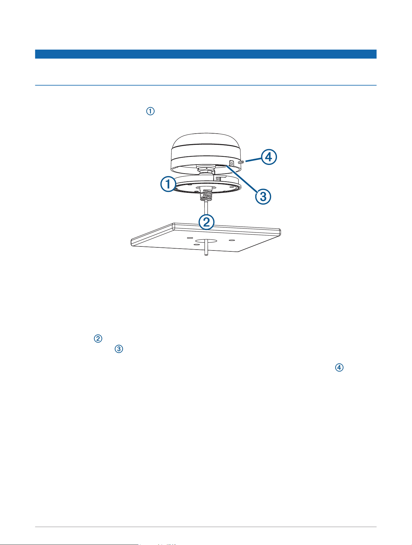
Surface Mounting the Antenna
NOTICE
If you are mounting the bracket on fiberglass with screws, it is recommended to use a countersink bit to drill a
clearance counterbore through only the top gel-coat layer. This will help to avoid cracking in the gel-coat layer
when the screws are tightened.
Before you permanently mount the antenna, you must test the mounting location for correct operation (Testing
the Mounting Location, page3).
1 Using the surface-mount bracket as your mounting template, mark the three pilot-hole locations and trace
the cable-hole in the center of the bracket.
2 Set the surface-mount bracket aside.
Do not drill through the bracket.
3 Use a 3.2mm (
1
/
8
in.) drill bit to drill the three pilot holes.
4 Use a 25mm (1in.) drill bit or hole saw to drill or cut the cable hole in the center.
5 Use the included M4 screws and a Phillips screwdriver to secure the surface-mount bracket to the mounting
surface.
If the included M4 screws are too short, use M4 screws of appropriate length.
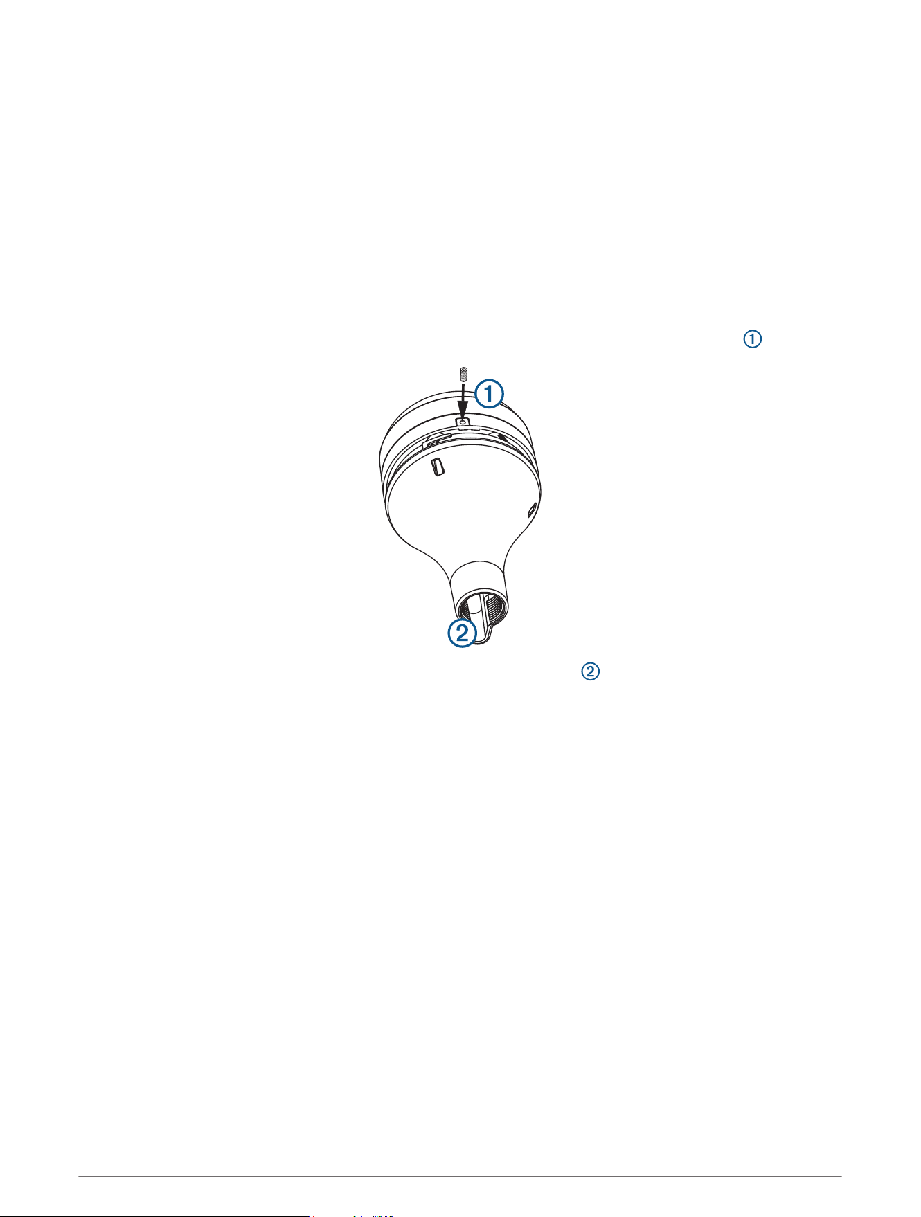
6 Route the cable through the center hole, and connect it to the antenna.
7 Verify the large gasket is in place on the bottom of the antenna, place the antenna on the surface-mount
bracket, and twist it clockwise to lock it in place.
8 Use the M3 set screw and a 1.5 mm hex wrench to secure the antenna to the mounting bracket .
9 Route the cable away from sources of electronic interference.
4
Mounting the Antenna with the Cable Routed Through the Pole
Before you permanently mount the antenna, you must test the mounting location for correct operation (Testing
the Mounting Location, page3).
1 Position a standard 1in. OD, 14 threads per inch, pipe-threaded pole (not included) in the selected location,
and mark the approximate center of the pole.
2 Use a 19mm (
3
/
4
in.) drill bit to drill a hole for the cable to pass through.
3 Fasten the pole to the boat.
4 Thread the pole-mount adapter onto the pole.
Do not overtighten the adapter.
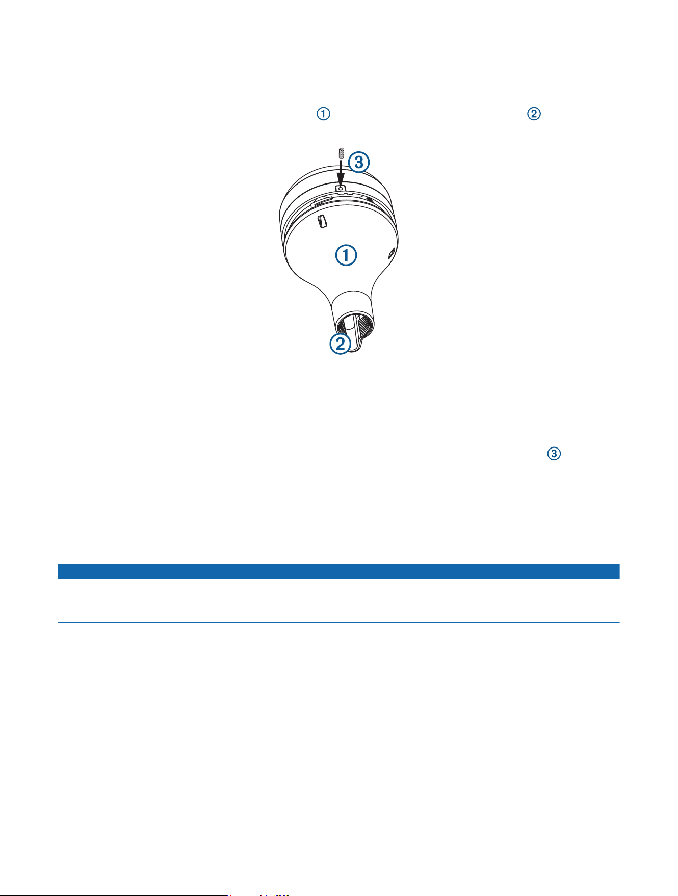
5 Route the cable through the pole and connect it to the antenna.
6 Place the antenna on the pole-mount adapter and twist it clockwise to lock it in place.
7 Use the included M3 set screw and a 1.5 mm hex wrench to secure the antenna to the adapter .
8 With the antenna installed on the pole mount, fill the vertical cable slot with a marine sealant (optional).
9 Route the cable away from sources of electronic interference.
5
Mounting the Antenna with the Cable Routed Outside the Pole
Before you permanently mount the antenna, you must test the mounting location for correct operation (Testing
the Mounting Location, page3).
1 Route the cable through the pole-mount adapter , and place the cable in the vertical slot along the base
of the pole-mount adapter.
2 Screw the pole-mount adapter onto a standard 1in. OD, 14 threads per inch, pipe-threaded pole (not
included).
Do not overtighten the adapter on the pole.
3 Connect the cable to the antenna.
4 Place the antenna on the pole-mount adapter and twist it clockwise to lock it in place.
5 Use the included M3 set screw and a 1.5 mm hex wrench to secure the antenna to the adapter .
6 With the antenna installed on the pole mount, fill the remaining gap in the vertical cable slot with a marine
sealant (optional).
7 Attach the pole to the boat if it is not already attached.
8 Route the cable away from sources of electronic interference.
Connection Considerations
NOTICE
If you are connecting the audio cable from the wiring harness, you must connect it to the line-in or auxiliary port
on a stereo. Attempting to connect the audio cable directly to a speaker will result in poor performance, and it
may cause the antenna to shut down, which might damage the antenna or the speaker.
You must connect this antenna to power and to the Garmin Marine Network to provide weather information to
connected, compatible Garmin devices.
6
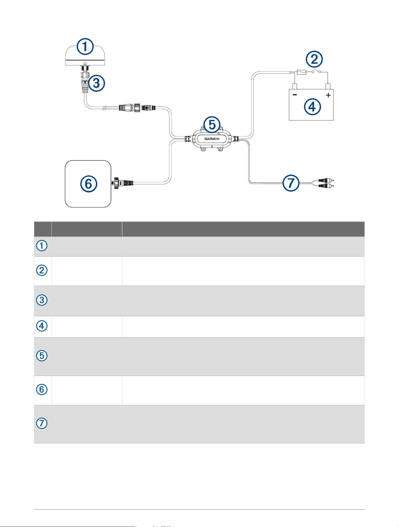
Item Description Notes
Antenna
Ignition or in-line
switch (not included)
You should connect the power and audio module to the battery through the
ignition switch or through an additional in-line switch (not included). Connecting
the harness directly to the battery may drain the battery.
Antenna cable
This Garmin Marine Network cable (small connector) connects the antenna to
the power audio module, and is 6m (20ft.) long.
Additional lengths are available from Garmin.
9 to 32Vdc power
source
Power and audio
module
You should install the module in a location with access to power, the installed
antenna, and a Garmin Marine Network device.
You can secure the module to existing cabling or a structure using zip ties (not
included), or you can secure it to a bulkhead using the included screws.
Garmin Marine
network device
If additional network ports are not available on the nearby Garmin Marine
Network device, you may need to use a GMS
™
10 to share weather data between
multiple chartplotters.
Audio out cable
Connects to the line-in or auxiliary port on a stereo to listen to SiriusXM stations.
You can extend this cable using a standard RCA cable if necessary. Extension-
cable connections should be made in a protected area that is not exposed to
water.
7

Activating a SiriusXM Subscription
1 With the SiriusXM source selected, tune to channel 1.
You should be able to hear the preview channel. If not, check the SiriusXM Connect Tuner and antenna
installation and connections, and try again.
2 Tune to channel 0 to locate the Radio ID.
3 Contact SiriusXM listener care by phone at (866) 635-2349 or go to www.siriusxm.com/activatenow to
subscribe in the United States. Contact SiriusXM by phone at (877) 438-9677 or go to www.siriusxm.ca
/activatexm to subscribe in Canada.
4 Provide the Radio ID.
The activation process usually takes 10 to 15 minutes, but can take up to an hour. For the SiriusXM Connect
Tuner to receive the activation message, it must be turned on and receiving the SiriusXM signal.
5 If the service is not activated within the hour, go to http://care.siriusxm.com/refresh or contact SiriusXM
Listener Care by phone at 1-866-635-2349.
Appendix
Specifications
Measurement Specification
Dimensions (diameter x height) 91.6 × 49.5mm (3.61 × 1.95in.)
Weight 221g (7.8oz)
Operating temperature range From -30° to 70°C (from -22° to 158°F)
Storage temperature range From -35° to 85°C (from -31° to 185°F)
Case material Fully gasketed, plastic and die-cast aluminum
Water rating IEC 60529 IPX7
1
Power input source From 9 to 32Vdc
Input current 500mAmax. at 12Vdc
Fuse 32V, 2A, mini-blade type, fast-acting
Antenna cable length 6m (20ft)
Power cable length 2m (6.5ft.)
Garmin Marine Network cable length 2m (6.5ft.)
Audio cable length 2m (6.5ft.)
1
The device withstands incidental exposure to water of up to 1m for up to 30min. For more information, go to www.garmin.com/waterrating.
8

Acknowledgment
Garmin SHALL HAVE NO LIABILITY IF CHANGES IN THE SERVICE PROVIDER'S SUBSCRIPTION OFFERING
NEGATIVELY IMPACTS OR RENDERS IMPOSSIBLE THE USE OF PURCHASED Garmin HARDWARE EQUIPMENT
WITH THE SERVICE PROVIDER'S OFFERING IN THE FUTURE.
THE USER AGREES THAT THE SiriusXM WEATHER SERVICE OFFERING IS PROVIDED "AS IS", THAT YOUR
Garmin HARDWARE EQUIPMENT ONLY ALLOWS THE DISPLAY OF SUCH SERVICE OFFERING, AND THAT ANY
CHANGES BY THE SERVICE PROVIDER MAY INTERFERE WITH THE ABILITY OF YOUR Garmin HARDWARE
EQUIPMENT TO RECEIVE OR DISPLAY SUCH SERVICE OFFERING. FURTHER, SUCH SERVICE OFFERING
CONTAINS INFORMATION FURNISHED BY OTHERS WHO ARE NOT UNDER THE CONTROL OF Garmin, AND
THEREFORE THE SERVICE OFFERING IS ACCORDINGLY FURNISHED WITHOUT ANY WARRANTY OF Garmin,
EXPRESS OR IMPLIED, INCLUDING WITHOUT LIMITATION, IMPLIED WARRANTIES OF MERCHANTABILITY AND
FITNESS FOR A PARTICULAR PURPOSE.
FCC Compliance
This device complies with part 15 of the FCC Rules. Operation is subject to the following two conditions: (1) this
device may not cause harmful interference, and (2) this device must accept any interference received, including
interference that may cause undesired operation.
This equipment has been tested and found to comply with the limits for a Class B digital device, pursuant
to part 15 of the FCC rules. These limits are designed to provide reasonable protection against harmful
interference in a residential installation. This equipment generates, uses, and can radiate radio frequency energy
and may cause harmful interference to radio communications if not installed and used in accordance with the
instructions. However, there is no guarantee that interference will not occur in a particular installation. If this
equipment does cause harmful interference to radio or television reception, which can be determined by turning
the equipment off and on, the user is encouraged to try to correct the interference by one of the following
measures:
• Reorient or relocate the receiving antenna.
• Increase the separation between the equipment and the receiver.
• Connect the equipment into an outlet that is on a different circuit from the GPS device.
• Consult the dealer or an experienced radio/TV technician for help.
This product does not contain any user-serviceable parts. Repairs should only be made by an authorized Garmin
service center. Unauthorized repairs or modifications could result in permanent damage to the equipment, and
void your warranty and your authority to operate this device under Part 15 regulations.
Innovation, Science and Economic Development Canada Compliance
This device contains licence-exempt transmitter(s)/receiver(s) that comply with Innovation, Science and
Economic Development Canada's licence-exempt RSS(s). Operation is subject to the following two conditions:
(1) this device may not cause interference, and (2) this device must accept any interference, including
interference that may cause undesired operation of the device.
Limited Warranty
The Garmin standard limited warranty applies to this accessory. For more information, go to www.garmin.com
/support/warranty.
© 2019 Garmin Ltd. or its subsidiaries
Garmin
®
and the Garmin logo are trademarks of Garmin Ltd. or its subsidiaries, registered in the USA and other countries. GXM
™
is a trademark of Garmin Ltd. or its
subsidiaries. These trademarks may not be used without the express permission of Garmin.
SiriusXM
®
is a registered trademark of SiriusXM Radio Inc.
Apple
®
is a trademark of Apple Inc., registered in the U.S. and other countries. Android
™
is a trademark of Google
™
Inc. Wi‑Fi
®
is a registered mark of Wi-Fi Alliance
Corporation. Windows
®
is a registered trademark of Microsoft Corporation in the United States and other countries.
All other trademarks and copyrights are the property of their respective owners.
This product may include open source software. This source, and modifications thereto, may be freely found at developer.garmin.com.
9

© 2019 Garmin Ltd. or its subsidiaries
support.garmin.com