
545FR, 545FX, 545FXT, 545RX, 545RXT,
545F
EN Operator's manual 2-35
Contents
Introduction..................................................................... 2
Safety..............................................................................4
Assembly...................................................................... 10
Operation...................................................................... 15
Maintenance................................................................. 22
Troubleshooting............................................................ 28
Transportation, storage and disposal........................... 29
Technical data.............................................................. 30
Accessories.................................................................. 32
Declaration of Conformity............................................. 34
Appendix ......................................................................36
Introduction
Product description
This product is a brushcutter with a combustion engine.
Work is constantly in progress to increase your safety
and efficiency during operation. Speak to your servicing
dealer for more information.
Intended use
Use the product with a saw blade, a grass blade or a
trimmer head to cut different types of vegetation. Do
not use the product for other tasks than grass trimming,
grass clearing and forestry clearing. Use a saw blade to
cut fibrous types of wood. Use a grass blade or trimmer
head to cut grass.
Note: National or local regulations can regulate the
use. Comply to given regulations.
Only use the product with accessories that are approved
by the manufacturer. Refer to
Accessories on page 32
.
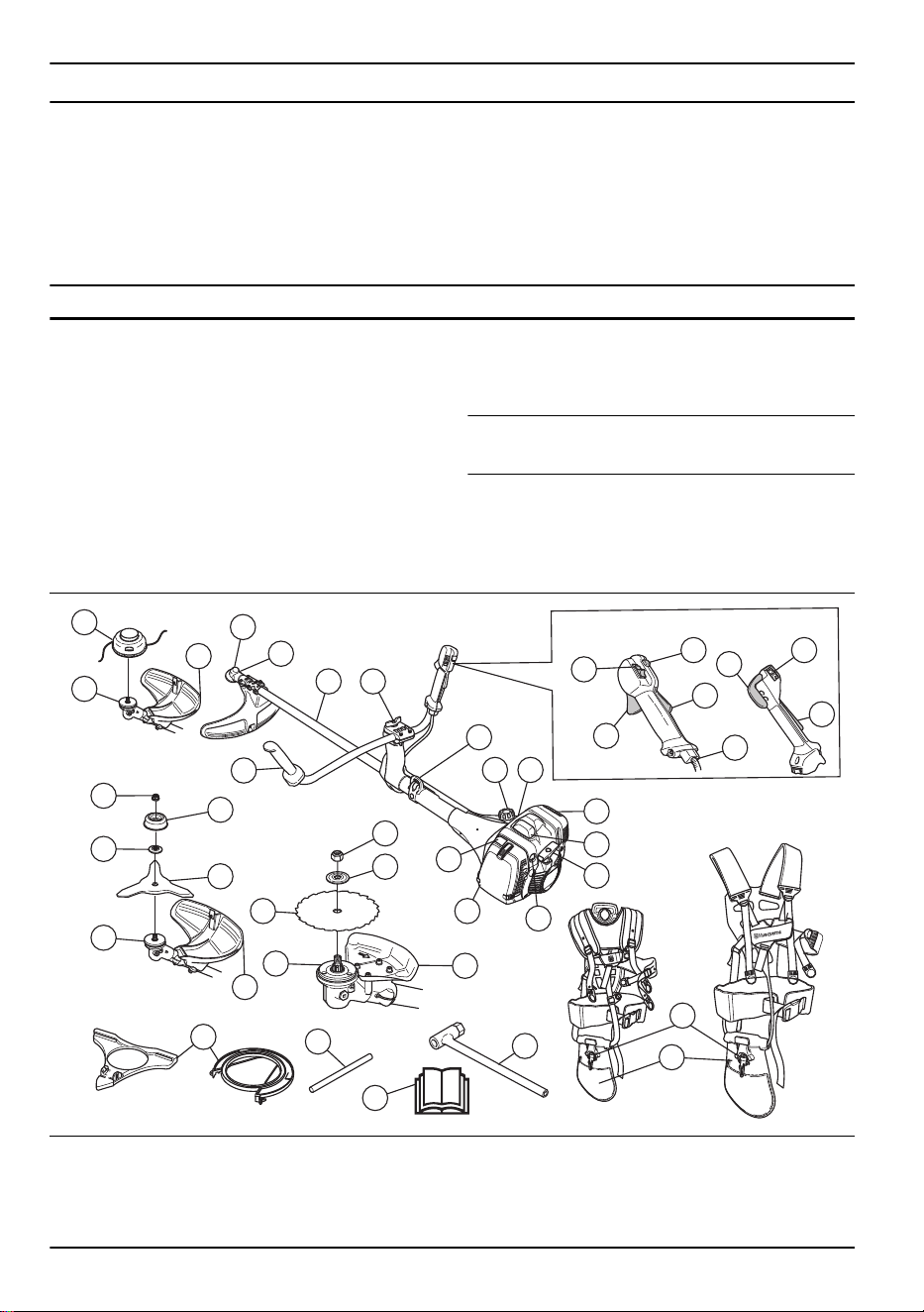
Product overview
11
23
33
31
32
30
25
27
26
2
24
25
24
1
29
27
26
24
3
25
28
6
5
4
7
13
14 15
16
17
18
19
20
21
22
9
8
12
11
10
9
8
545FR, 545RX,RXT
545F, FX, FXT
1. Grass blade
2. Saw blade
3. Trimmer head
4. Bevel gear
5. Grease fill cap, bevel gear
6. Shaft
2 1018 - 013 - 14.12.2023

7. Handle adjustment
8. Throttle trigger
9. Stop switch
10. Start throttle button
11. Throttle trigger lockout
12. Throttle wire adjustment
13. Suspension point
14. Fuel tank
15. Decompression valve
16. Muffler
17. Spark plug cap and spark plug, below the cover
18. Starter rope handle
19. Air purge bulb
20. Air filter cover
21. Choke control
22. Harness, safety-release mechanism
23. Harness, hip pad
24. Drive disc
25. Cutting attachment guard
26. Locknut
27. Support cup
28. Handlebar
29. Support flange
30. Transport guard
31. Locking pin
32. Operator's manual
33. Socket wrench
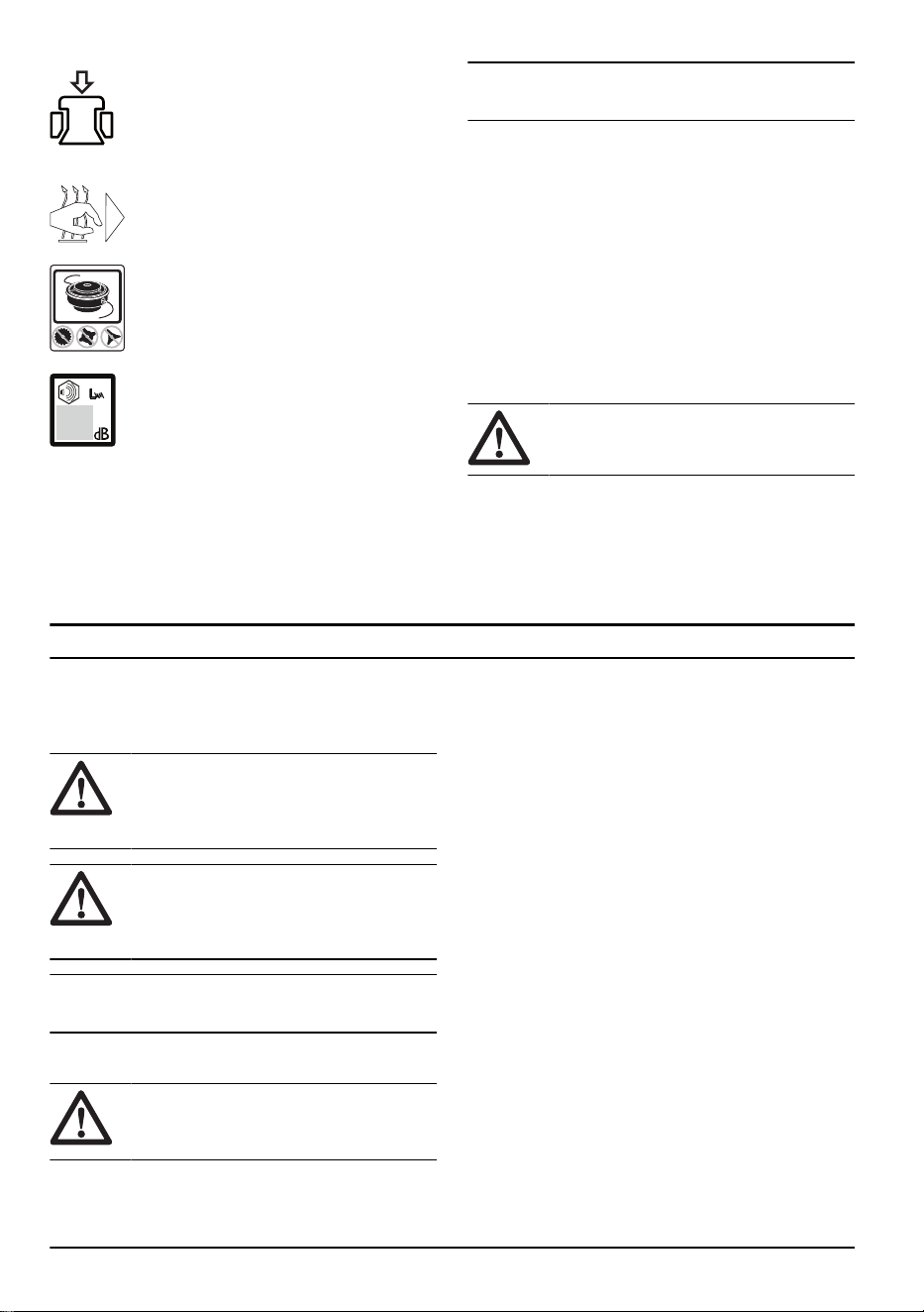
Symbols on the product
Stop.
WARNING! Be careful and use the
product correctly. This product can cause
serious injury or death to the operator or
others.
Read the operator's manual carefully
and make sure that you understand the
instructions before use.
Use a protective helmet in locations where
objects can fall on you. Use approved
hearing protection. Use approved eye
protection.
Maximum speed of the output shaft.
The product agrees with the applicable
EC directives.
This product conforms to the applicable
UK regulations.
The product can cause objects to eject,
which can cause injury.
5
0
FT
1
5
m
50F
T
15 m
Keep a minimum distance of 15 m/49 ft to
persons and animals during operation of
the product.
Risk of blade thrust if the cutting
equipment touches an object that it does
not immediately cut. The product can cut
off body parts. Keep a minimum of 15
m/49 ft distance to persons and animals
during operation of the product.
Use approved protective gloves.
Use heavy-duty slip-resistant boots.
Air purge bulb.
Choke.
Idle adjustment screw.
High speed needle.
Low speed needle.
Fuel.
1018 - 013 - 14.12.2023 3
Decompression valve.
Heated handles.
Only use a flexible cutting wire. Do not
use metal cutting attachments. Apply this
for grass guard accessory.
Noise emission to the environment label
as per EU (also including New South
Wales legislation) and UK directives
and regulations. The guaranteed sound
power level of the product is specified in
Technical data on page 30
and on the
label.
yyyywwxxxx The rating plate shows the
serial number. yyyy is the
production year and ww is
the production week.
Note: Other symbols/decals on the product refer to
certification requirements for other commercial areas.
Product damage
We are not responsible for damages to our product if:
• the product is incorrectly repaired.
• the product is repaired with parts that are not
from the manufacturer or not approved by the
manufacturer.
• the product has an accessory that is not from the
manufacturer or not approved by the manufacturer.
• the product is not repaired at an approved service
center or by an approved authority.
Euro V Emissions
WARNING: Tampering with the engine
voids the EU type-approval of this product.
Safety
Safety definitions
Warnings, cautions and notes are used to point out
specially important parts of the manual.
WARNING: Used if there is a risk of
injury or death for the operator or bystanders
if the instructions in the manual are not
obeyed.
CAUTION: Used if there is a risk of
damage to the product, other materials or
the adjacent area if the instructions in the
manual are not obeyed.
Note: Used to give more information that is necessary
in a given situation.
General safety instructions
WARNING: Read the warning
instructions that follow before you use the
product.
• This product produces an electromagnetic field
during operation. This field may under some
circumstances interfere with active or passive
medical implants. To reduce the risk of serious or
fatal injury we recommend persons with medical
implants to consult their physician and the medical
implant manufacturer before operating this product.
• Do not use the product if you are tired, ill, or
under the influence of alcohol, drugs or medicine.
This has a negative effect on your vision, alertness,
coordination and judgment.
• Do not operate the product in bad weather, such
as dense fog, heavy rain, strong wind and intense
cold. To operate the product in bad weather can
make you tired and add risks, such as icy ground
and unpredictable felling direction.
• Always be careful and use your common sense.
If you feel uncertain about a work situation or the
operating procedures after you read the operator's
manual, speak to a servicing dealer before you
continue.
• Remove the spark plug cap if you let the product out
of view.
• A used muffler/spark arrester and spark arrester
mounting face may contain deposits of combustion
particles that may be carcinogenic. Avoid being
exposed to these compounds when handling the
muffler and/or spark arrester. Prior to any handling
of the muffler and/or the spark arrester, refer to
To
do a check of the muffler on page 8
.
4 1018 - 013 - 14.12.2023
Safety instructions for assembly
WARNING: Read the warning
instructions that follow before you use the
product.
• Use approved protective gloves when you assemble
the product and cutting attachment.
• Remove the spark plug cap from the spark plug
before you assemble the product.
• Make sure that the correct handlebar and cutting
attachment guard are assembled before you operate
the product.
• A damaged or incorrect cutting attachment guard
can cause injury. Do not use a cutting attachment
without an approved cutting attachment guard.
• Attach the clutch cover and shaft correctly before
you start the product.
• The drive disc and support flange must engage
correctly in the center hole of the cutting attachment.
A cutting attachment that is attached incorrectly can
cause injury or death.
• Attach the harness to the product to prevent injury to
the operator or others.
Safety instructions for operation
WARNING: Read the warning
instructions that follow before you use the
product.
• Learn and understand the difference between
forestry clearing, grass clearing and grass trimming
before you use the product.
• Use personal protective equipment, refer to
Personal
protective equipment on page 6
.
• Long-term exposure to noise can result in permanent
hearing loss. Always use approved hearing
protection.
• Listen for warning signals and loud voices when you
use hearing protection. Always remove your hearing
protection when the engine stops.
• Never use the product if it is changed or damaged.
• Make sure that the spark plug cap and ignition lead
are not damaged to prevent the risk of electrical
shock.
• Look around the work area to make sure that no
persons, animals or objects have a negative effect
on the safety of the operation of the product.
• Look around the work area to make sure that no
persons or animals touch the cutting attachment or
are hit by objects that are ejected from the cutting
attachment.
• Do not use the product in a situation or location
where you can not get aid if an accident occurs.
• Do not use the product without an approved cutting
attachment guard.
• Make sure that persons or animals keep a distance
of a minimum of 15 m/50 ft during work. Always look
behind you before you turn around with the product.
Stop the product immediately if a person or animal
enters the 15 m/50 ft safety zone. If more than 1
operator does work in the same area, keep a safety
distance of a minimum of 2 times the tree height and
a minimum of 15 m/50 ft.
• Examine the work area. Avoid loose objects, such as
stones, broken glass, nails, steel wire and string, that
can eject or wind around the cutting attachment.
• Make sure that you can move safely and have a safe
stance. Examine the area around you for obstacles
such as roots, rocks, branch and ditches. Be careful
during work on slopes.
• Do not overreach. Keep a stable position of the feet
and a good balance at all times.
• Before you start the product, put it on a flat surface,
at a minimum ot 3 m/10 ft from the fuel source and
from where you fill fuel. Make sure that there are no
objects near or touching the cutting attachment.
• If the cutting attachment rotates at idle speed, let a
service agent adjust it. Do not use the product until it
is adjusted or repaired.
• Look out for thrown objects. Always use approved
eye protection and keep away from the cutting
attachment guard. Stones and other small objects
can eject into your eyes and cause blindness or
other injuries.
• Do not put the product down with the engine on
unless you have it in clear view.
• Do not remove the cut material, or let other persons
remove cut material, while the engine is on or
the cutting equipment rotates, as this can result in
serious injury.
• Always stop the engine and make sure that the
cutting equipment does not rotate before you remove
material that is wound around the blade shaft or
caught between the cutting attachment guard and
the cutting attachment.
• Be careful when you remove material from around
the cutting equipment. The bevel gear gets hot
during operation and can cause burn injuries.
• The exhaust fumes from the engine are hot and can
contain sparks. Risk of fire. Be careful around dry
and flammable material.
1018 - 013 - 14.12.2023
5
• Never use the product indoors or in spaces lacking
proper ventilation. Exhaust fumes contain carbon
monoxide, an odourless, poisonous and highly
dangerous gas.
• Stop the engine before you move to a new work
area. Always attach the transport guard before you
move the equipment.
• Overexposure to vibration can lead to circulatory
damage or nerve damage in persons who have
poor circulation. Speak to your physician if you
experience symptoms of overexposure to vibration.
Such symptoms include numbness, loss of feeling,
tingling, pricking, pain, loss of strength, changes in
skin colour or condition. These symptoms usually
show in the fingers, hands or wrists. The risk
increases at low temperatures.
Personal protective equipment
WARNING: Read the warning
instructions that follow before you use the
product.
• Always use approved personal protective equipment
when you use the product. Personal protective
equipment cannot fully prevent injury but it
decreases the degree of injury if an accident does
occur. Let your dealer help you select the correct
equipment.
• Use a helmet if the trees in the work area have a
height of more than 2 m/6.5 ft.
• Use approved hearing protection.
• Always use approved protective googles that comply
with ANSI Z87.1 standard in the USA or EN 166 in
EU countries.Use visor for face protection. Visor is
not enough to protect the eyes.
+
• Use gloves when it is necessary, for example when
you attach, examine or clean the cutting equipment.
• Use protective boots with steel toe-cap and non-slip
soles.
• Use clothing made of a strong fabric. Always use
heavy, long pants and long sleeves. Do not use
loose clothing that can catch on twigs and branches.
Do not use jewelry, short pants or sandals. Do not
go with bare feet. Put your hair up safely above
shoulder level.
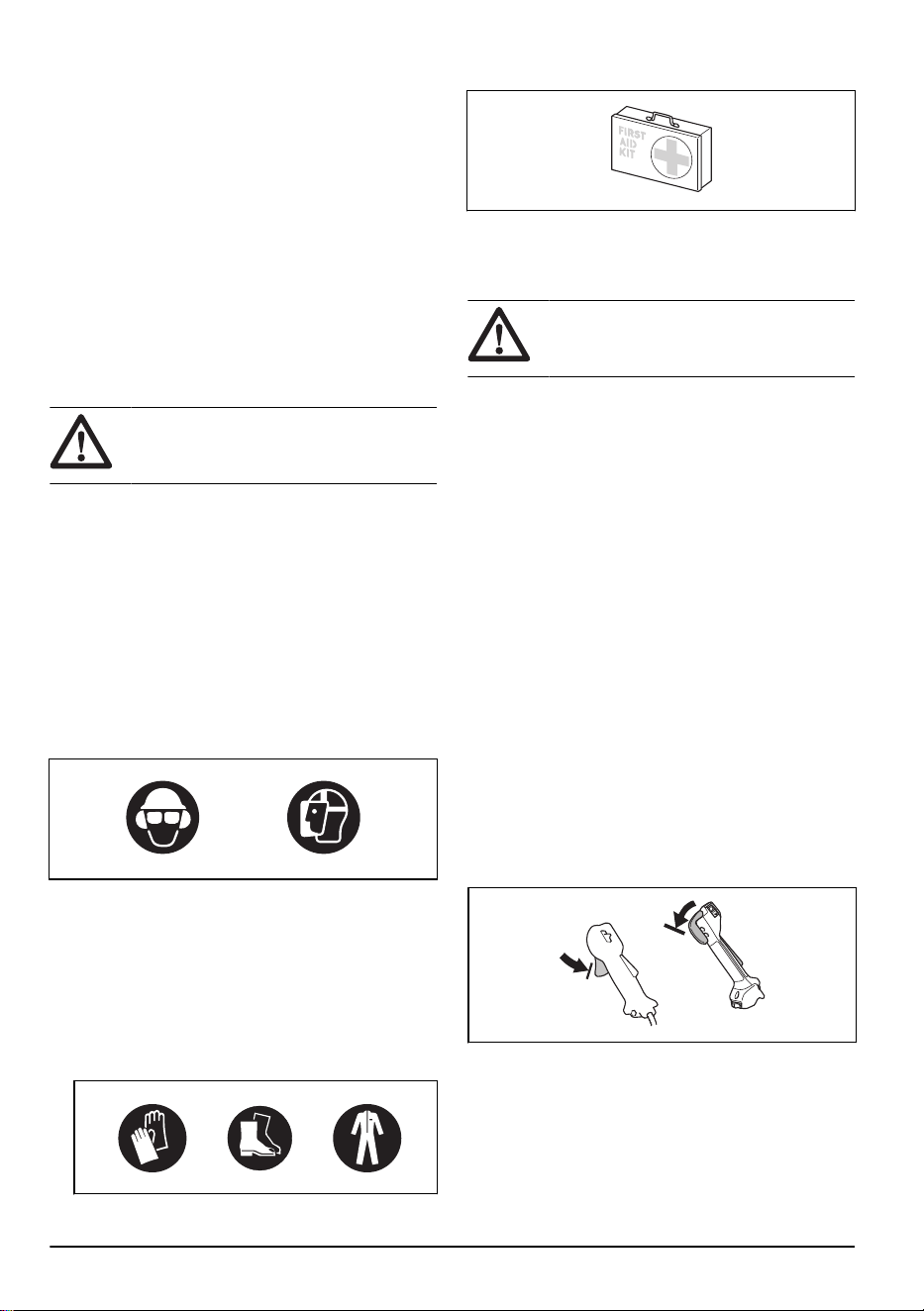
• Keep first aid equipment near.
Safety devices on the product
For information about where to find the safety devices,
see
Product overview on page 2
.
WARNING: Read the warning
instructions that follow before you use the
product.
• Do not use a product with damaged safety devices.
Do a check of and do maintenance on the safety
devices regularly. If the safety devices are damaged,
speak to your Husqvarna service agent.
• Do not make changes to safety devices. Do not
use the product if protective covers, safety switches
or other protective devices are not attached or are
damaged.
• For all service and repair work on the product,
especially for the safety devices, special training is
necessary. If the safety devices fail the checks given
in this operator's manual, you must let a service
agent help you. We guarantee that professional
repairs and service is available. If your dealer is not
a service agent, speak to them for information about
the nearest service agent.
• Do not use a cutting attachment without an approved
and correctly attached cutting attachment guard. See
To assemble the cutting equipment on page 11
.
To do a check of the throttle trigger lockout
The throttle trigger lockout locks the throttle trigger at the
idle position.
1. Press the throttle trigger (B) and make sure that it is
locked.
6
1018 - 013 - 14.12.2023
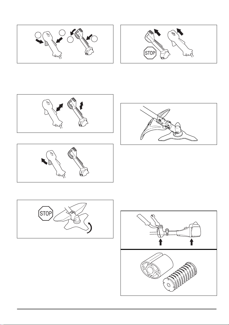
2. Press the throttle trigger lockout (A). Make sure that
the throttle trigger (B) is released.
A
A
B
B
3. Release the handle and make sure that the throttle
trigger lockout (A) and the throttle trigger (B) go back
to their initial positions.
4. Press the throttle trigger lockout (A) and make sure
that it goes back to its initial position when you
release it.
5. Press the throttle trigger (B) and make sure that it
goes back to its initial position when you release it.
6. Start the engine and apply full throttle.
7. Release the throttle trigger and make sure that the
cutting attachment stops.
To do a check of the stop switch
1. Start the engine.
2. Move the stop switch to the stop position and make
sure that the engine stops.
To do a check of the cutting attachment guard
The cutting attachment guard stops objects that ejects in
the direction of the operator. It also prevents injuries that
occur if you touch the cutting attachment.
1. Stop the engine.
2. Do a visual check for damages, for example cracks.
3. Replace the cutting attachment guard if it is
damaged.
To do a check of the vibration damping system
The vibration damping system decreases vibration in
the handles to a minimum which makes the operation
easier.
1. Stop the engine.
2. Do a visual check for deformation and damage for
example, cracks.
3. Make sure you attach the elements of the vibration
damping system are correctly.
1018 - 013 - 14.12.2023
7
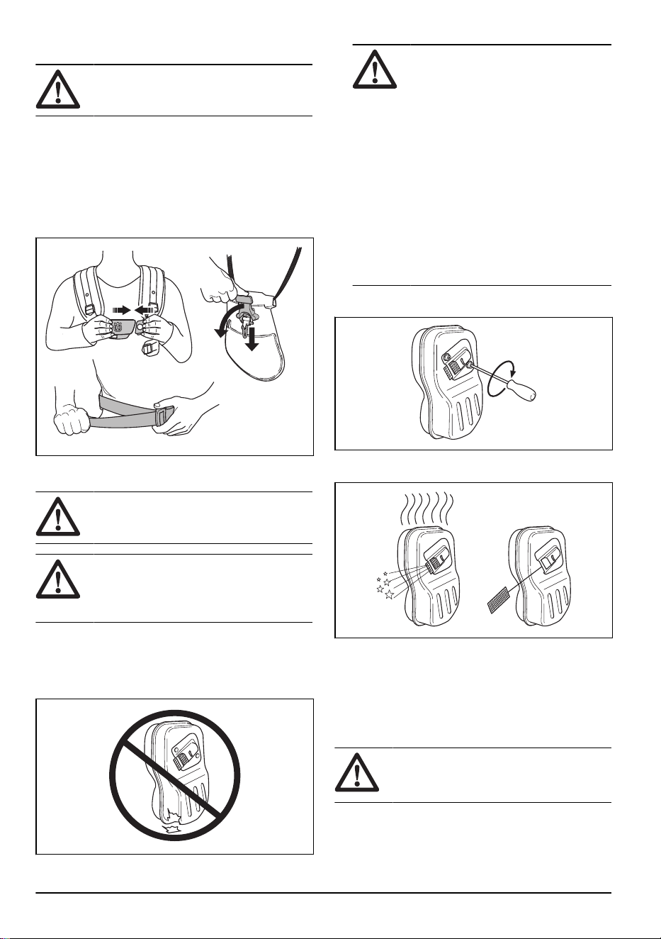
To do a check of the safety-release mechanism
WARNING: Do not use a harness with
a damaged safety-release mechanism.
The safety-release mechanism lets the operator remove
the product quickly from the harness if there is an
emergency.
1. Stop the engine.
2. Do a visual check for damages, such as cracks.
3. Release and attach the safety-release mechanism to
make sure that it operates correctly.
To do a check of the muffler
WARNING: Do not use a product with
a damaged muffler.
WARNING: The mufflers become very
hot during and after operation, also at idle
speed. Use protective gloves to prevent burn
injuries.
The muffler keeps noise levels to a minimum and sends
exhaust fumes away from the operator.
1. Stop the engine.
2. Do a visual check for damage and deformation.
WARNING:
A used muffler/spark
arrester and spark arrester mounting
face may contain deposits of combustion
particles on the surfaces that may be
carcinogenic. To avoid skin contact
and inhalation of such particles when
cleaning and/or servicing the spark
arrester, make sure you always:
• wear gloves;
• clean and/or service in a well
ventilated area;
• do not use pressurized air to clean
the spark arrester screen;
• use a steel brush and brush away
from your body when cleaning the
spark arrester.
3. Make sure that the muffler is correctly attached to
the product.
4. If the muffler on your product has a spark arrester
screen, do a visual check.
a) Replace the spark arrester screen if it is
damaged.
b) Clean the spark arrester screen if it is blocked.
See
To clean the muffler on page 24
for more
information.
To do a check of the locknut
WARNING:
Stop the engine, use
protective gloves and be careful around the
sharp edges of the cutting attachment.
• Make sure that the locknut is attached and tightened
correctly. Refer to
To attach and remove the locknut
on page 26
.
8
1018 - 013 - 14.12.2023

Cutting attachment
WARNING: Read the warning
instructions that follow before you use the
product.
• Do the regular maintenance. Let an approved
service center regularly examine the cutting
attachment to do adjustments or repairs.
• The performance of the cutting attachment
increases.
• The life of the cutting attachment increases.
• The risk of accidents decreases.
• Only use an approved cutting attachment guard.
Refer to
Accessories on page 32
.
• Do not use a damaged cutting attachment.
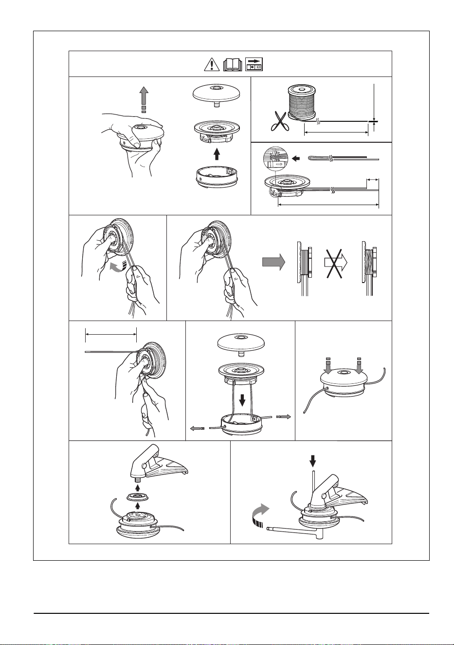
Grass trimmer head
• Make sure that you wind the grass trimmer line
tightly and equally around the drum to decrease the
vibration.
• Use only the approved grass trimmer heads and
grass trimmer lines. Refer to
Accessories on page
32
.
• Use a correct length of the grass trimmer line. A long
grass trimmer line uses more engine power than a
short grass trimmer line.
• Make sure that the cutter on the cutting attachment
guard is not damaged.
• Soak the grass trimmer line in water for 2 days
before you attach the grass trimmer line to the
product. This increases the life of the grass trimmer
line.
• Refer to the instructions for the cutting attachment to
use the correct procedure to load the cord and the
correct cord diameter.
Saw blade and grass blade
• Use correctly sharpened blades. An incorrectly
sharpened or damaged blade increases the risk of
injury.
• Use correctly set blades. Correct blade set is 1 mm.
An incorrectly set blade increases the risk of injury
and damage.
• To sharpen and set the blade correctly, refer to the
instructions that come with the blade.
Fuel safety
WARNING:
Read the warning
instructions that follow before you use the
product.
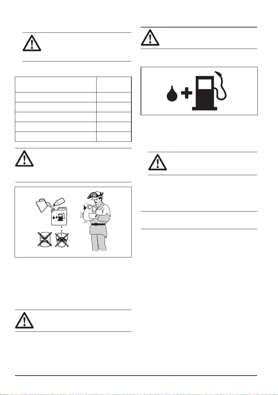
• Do not mix the fuel indoor or near a heat source.
• Do not start the product if there is fuel or engine oil
on the product. Remove the unwanted fuel/oil and
let the product dry. Remove unwanted fuel from the
product.
• If you spill fuel on your clothing, change clothing
immediately.
• Do not get fuel on your body, it can cause injury. If
you get fuel on your body, use a soap and water to
remove the fuel.
• Do not start the engine if you spill oil or fuel on the
product or on your body.
• Do not start the product if the engine has a leak.
Examine the engine for leaks regularly.
• Be careful with fuel. Fuel is flammable and the fumes
are explosive and can cause injuries or death.
• Do not breathe in the fuel fumes, it can cause injury.
Make sure that there is sufficient airflow.
• Do not smoke near the fuel or the engine.
• Do not put warm objects near the fuel or the engine.
• Do not add the fuel when the engine is on.
• Make sure that the engine is cool before you refuel.
• Before you refuel, open the fuel tank cap slowly and
release the pressure carefully.
• Make sure there are sufficient airflow when refueling
and mixing fuel (petrol and two-stroke oil) or draining
the fuel tank.
• Fuel and fuel vapor are highly flammable and can
cause serious injury when inhaled or allowed to
come into contact with the skin. For this reason,
observe caution when handling fuel and make sure
there is sufficient airflow.
• Tighten the fuel tank cap carefully or a fire can
occur.
• Move the product at a minimum of 3 m (10 ft) from
the position where you filled the tank before a start.
• Do not put too much fuel in the fuel tank.
• Make sure that a leak cannot occur when you move
the product or fuel container.
• Do not put the product or a fuel container where
there is an open flame, spark or pilot light. Make
sure that the storage area does not contain an open
flame.
• Only use approved containers when you move the
fuel or put the fuel into storage.
• Empty the fuel tank before long-term storage. Obey
the local law on where to dispose fuel.
• Clean the product before long-term storage.
• Remove the spark plug cap before you put the
product into storage to make sure that the engine
does not start accidentally.
Safety instructions for maintenance
WARNING:
Read the warning
instructions that follow before you use the
product.
• Stop the engine, make sure that the cutting
attachment stops. Remove the cylinder cover and
1018 - 013 - 14.12.2023
9
disconnect the spark plug cap before you do the
maintenance.
• The exhaust fumes from the engine contain carbon
monoxide, an odourless, poisonous and very
dangerous gas that can cause death. Do not run the
product indoors or in closed spaces.
• The exhaust fumes from the engine are hot and can
contain sparks. Do not run the product indoors or
near flammable material.
• Accessories and changes to the product that are not
approved by the manufacturer, can cause serious
injury or death. Do not change the product. Always
use original accessories.
• If the maintenance is not done correctly and
regularly, there is an increased risk of injury and
damage to the product.
• Only do the maintenance as this operator's manual
recommends. Let an approved Husqvarna service
agent do all other servicing.
• Let an approved Husqvarna service agent do
servicing on the product regularly.
• Replace damaged, worn or broken parts.
Assembly
Introduction
WARNING: Before you assemble the
product, you must read and understand the
safety chapter.
WARNING: Remove the spark plug
cable from the spark plug before you
assemble the product.
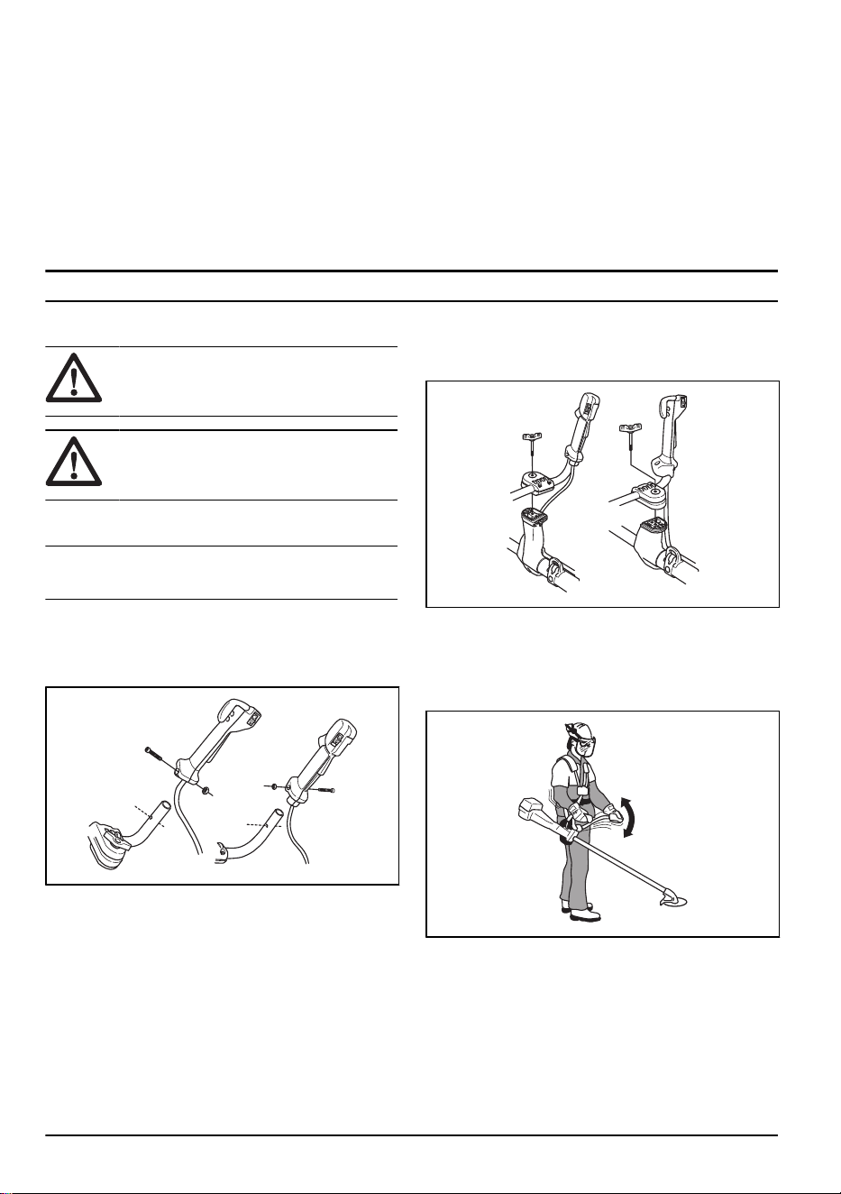
To attach the throttle handle
Note: On some models, the throttle handle is attached
at the factory.
1. Remove the nut and screw at the bottom of the
throttle handle.
2. Put the throttle handle onto the right side of the
handlebar.
3. Align the screw hole in the throttle handle with the
hole in the handlebar.
4. Put the screw into the hole at the bottom of the
throttle handle, through the handlebar.
5. Put back and tighten the nut.
To assemble the handlebar
1. Remove the knob and attach the handlebar as given
in the illustration.
2. Tighten the knob lightly.
3. Put on the harness and hang the product from the
suspension point.
4. Adjust the handle to put the product in a comfortable
work position.
5. Tighten the knob fully.
To set the handlebar in transport
position
1. Loosen the knob.
2. Turn the handlebar clockwise until the throttle handle
touches the battery.
10
1018 - 013 - 14.12.2023
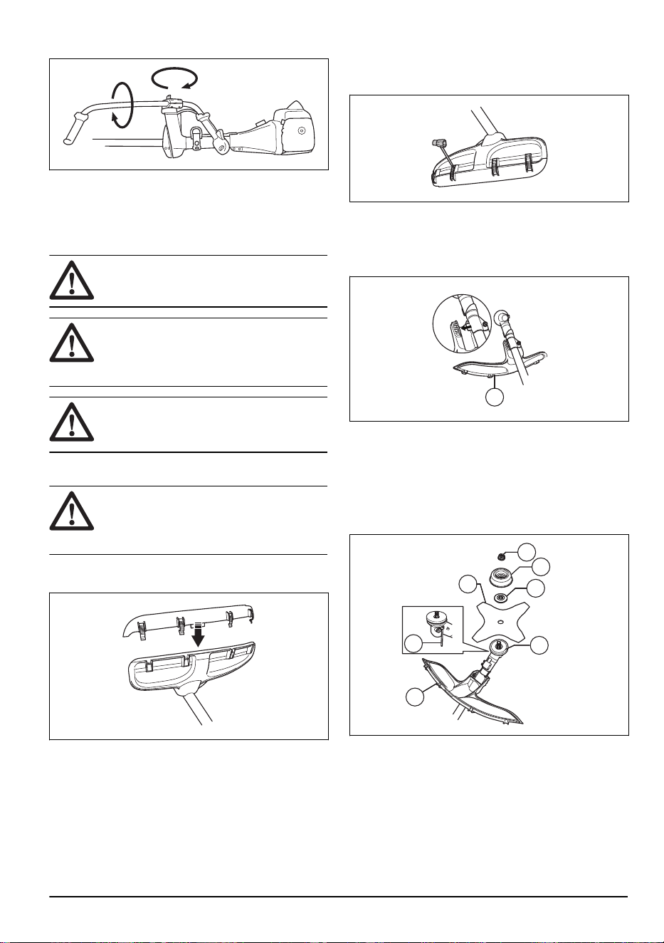
3. Turn the handlebar around the shaft.
4. Tighten the knob.
To assemble the cutting equipment
The cutting equipment includes a cutting attachment and
a cutting attachment guard.
WARNING: Use protective gloves.
WARNING: Always use the cutting
attachment guard that is recommended for
the cutting attachment. See
Accessories on
page 32
.
WARNING: An incorrectly attached
cutting attachment can result in injury or
death.
To attach the guard extension
CAUTION:
Use the guard extension
when you use a trimmer head/plastic blade.
Do not use the guard extension when you
use a grass blade.
1. Put the guard extension in the groove of the cutting
attachment guard.
2. Put the guard extension into position on the cutting
attachment guard with the 4 locking hooks.
To remove the guard extension
• Release the locking hooks with the spark plug
wrench.
To attach the grass blade and the grass blade
guard/combination guard
1. Put the blade guard/combination guard (A) onto the
shaft and tighten the bolt to attach it.
A
2. Make sure that the guard extension is removed.
3. Turn the output shaft to align one of the holes in
the drive disc (B) with the related hole in the gear
housing.
4. Put the locking pin (C) in the hole to lock the shaft.
5. Put the grass blade (D), the support flange (F) and
the support cup (E) on the output shaft.
G
F
D
B
C
A
E
1018 - 013 - 14.12.2023
11
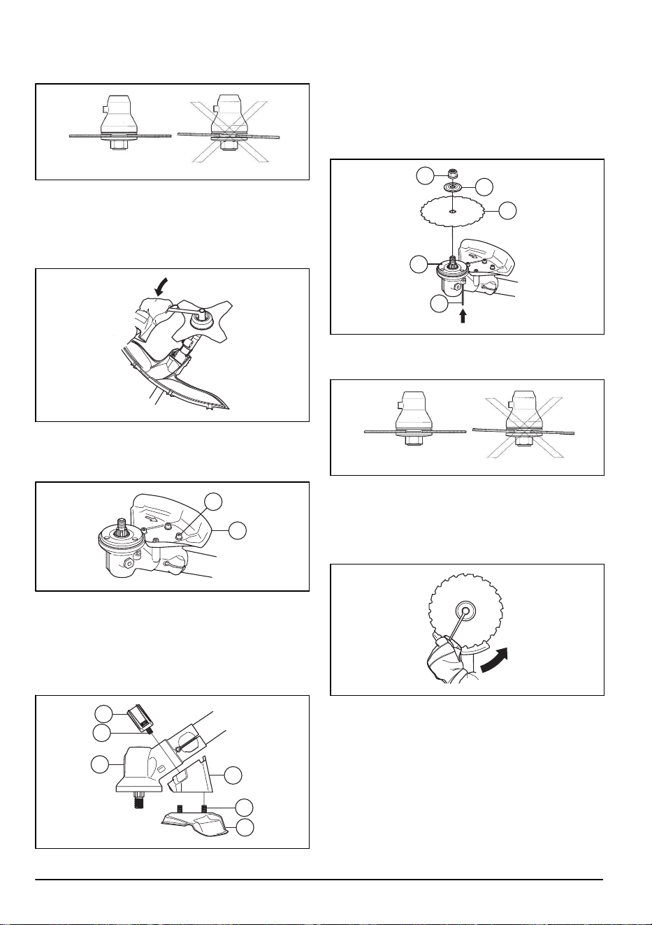
6. Make sure that the drive disc and support flange
engages correctly in the centre hole of the grass
blade.
7. Attach the nut (G).
8. Tighten the nut with the socket wrench. Hold the
shaft of the socket wrench near the blade guard.
Tighten in the opposite direction to how the cutting
attachment rotates. Tighten it to a torque of 35-50
Nm.
To attach the saw blade guard on 545FX,
545FXT and 545F
• Attach the saw blade guard (A) with the 4 screws (L).
A
L
To attach the saw blade guard 545FR, 545RX,
545RXT
1. Attach the holder (A) and bracket (B) with 2 bolts (C)
on the gear housing (D).
2. Attach the saw blade guard (E) with 4 bolts (F) in the
holder (A).
B
C
D
F
A
E
To attach the saw blade
1. Put the drive disc (A) on the output shaft.
2. Turn the output shaft to align 1 of the holes in the
drive disc with the related hole in the gear housing.
3. Put the locking pin (B) in the hole to lock the shaft.
4. Put the saw blade (C) and the support flange (D) on
the output shaft.
D
E
C
A
B
5. Make sure that the drive disc and support flange
engages correctly in the center hole of the grass
blade.
6. Attach the locknut (E).
7. Tighten the locknut with the socket wrench. Hold the
shaft of the socket wrench near the blade guard.
Tighten in the opposite direction to how the cutting
attachment rotates. Tighten it to a torque of 35-50
Nm.
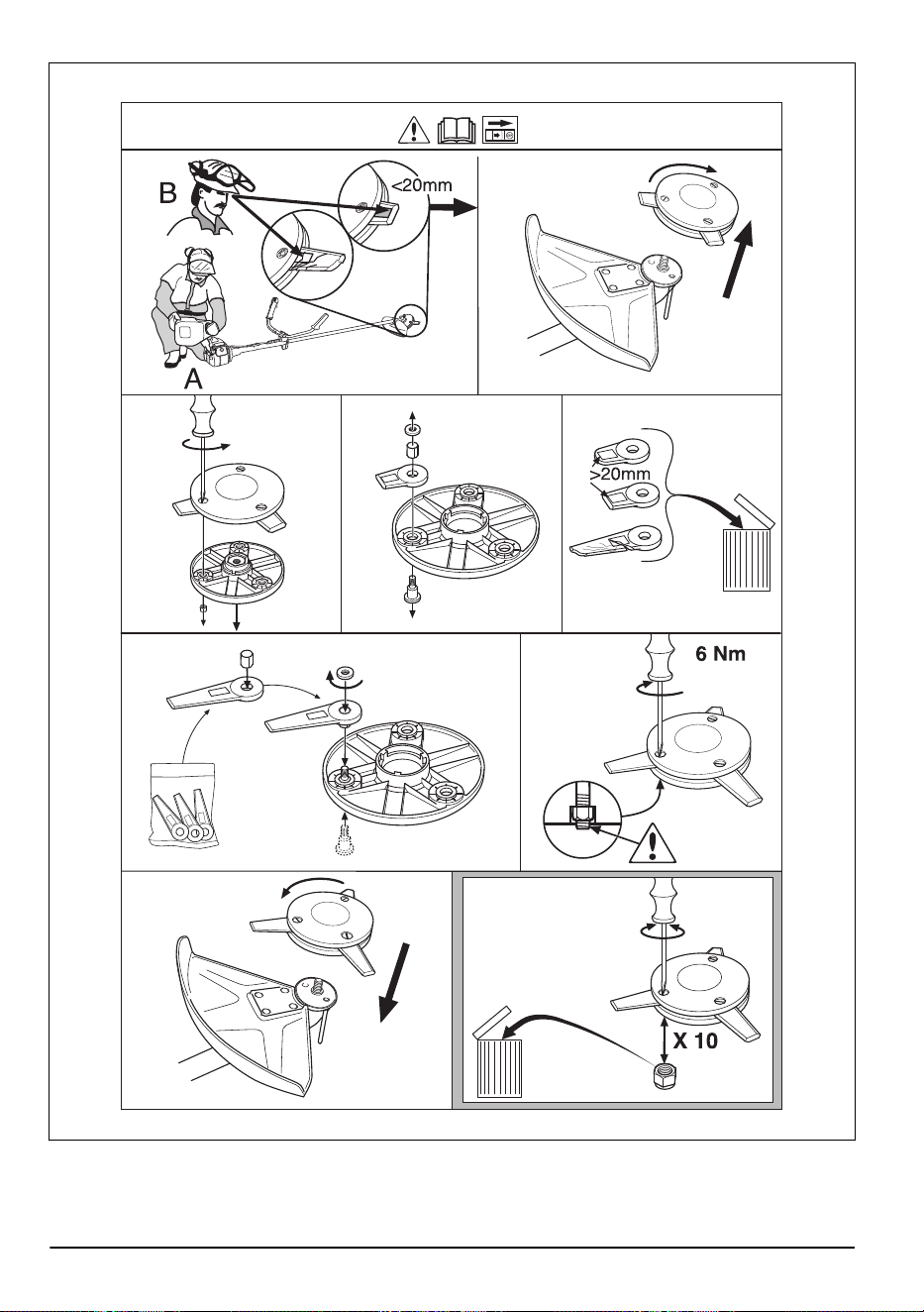
To attach the trimmer guard or combination
guard for trimmer head and plastic blades
1. Hang the trimmer guard/combination guard (A) onto
the two hooks on the plate holder (M).
2. Bend the guard around the shaft and attach it with
the bolt (L) on the opposite side of the shaft.
12
1018 - 013 - 14.12.2023
3. Put the locking pin (C) in the groove on the bolt head
and tighten the bolt fully.
L
A
M
C
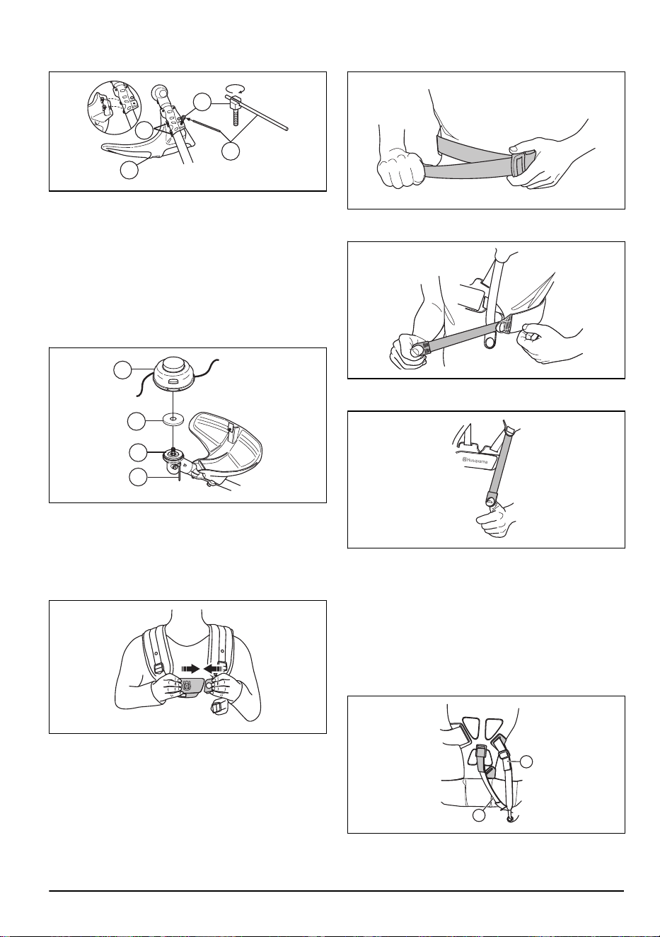
To attach a trimmer head or plastic blade
1. Put the drive disc (B) on the output shaft.
2. Align the metal cup (P) with the center of the blade
guide on the drive disc.
3. Turn the output shaft to align one of the holes in the
drive disc with the related hole in the gear housing.
4. Put the locking pin (C) in the hole to lock the shaft.
5. Turn the trimmer head/plastic blades (H)
counterclockwise to attach.
B
H
P
C
To adjust the Balance X harness
545FR, 545RX
1. Put the harness on.
2. Push the 2 parts of the breastplate together as
shown in the illustration.
3. Tighten the hip strap tightly. Make sure that the hip
strap aligns with the hip.
4. Tighten the chest strap below your left arm tightly.
The chest strap must be tight against your body.
5. Adjust the shoulder strap until the weight is equal on
the 2 shoulders.
6. Adjust the height of the suspension point.
For forestry clearing, the correct height of the
suspension is approximately 10 cm below your hip.
Refer to
Correct balance of the product on page 16
.
7. It can be necessary to lower the suspension point
when you trim grass. If it is necessary, move the
suspension strap (A) to the lower suspension point
on the harness.
8. Tighten the elastic strap (B) to move the load from
the shoulders to the hip.
A
B
1018 - 013 - 14.12.2023
13
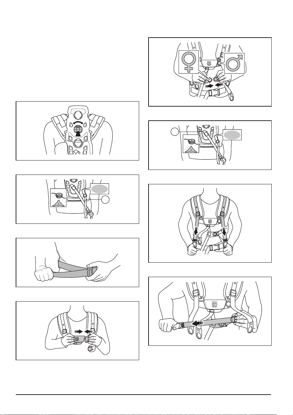
To adjust the Balance XT harness
Refer to
Product overview on page 2
for an overview of
the harness.
1. Stop the engine.
2. Push the safety-release mechanism down to release
the product from the harness.
3. To adjust the harness to the operator's height:
a) Push the spring loaded lock.
b) Turn the shoulder strap harness.
c) Move the shoulder strap harness to an applicable
hole on the back plate.
4. Attach the strap (A) in correct position for grass
clearing or forestry clearing.
A
5. Tighten the hip strap tightly. Make sure that the hip
strap aligns with the hip.
6. Push the 2 parts of the breastplate together as
shown.
7. Attach the side belt to the breastplate.
8. To decrease the pressure on the rib cage and
shoulders, connect the side strap with the strap to
the hip pad. Recommended for women.
9. Tighten the elastic strap (B) to move more load from
the shoulder strap to the hip strap.
B
10. Adjust the shoulder strap to make the product weigh
equally on your shoulders.
11. Adjust the side straps around the rib cage until the
breastplate is aligned with the center of your chest.
12. Adjust the height of the suspension point. Refer to
Product overview on page 2
. For forestry clearing,
the correct height of the suspension is approximately
10 cm/4 in below your hip.
14
1018 - 013 - 14.12.2023
Operation
Introduction
WARNING: Before you operate the
product, you must read and understand the
safety chapter.
Before you operate the product
• Examine the work area to make sure that you know
the type of terrain, the slope of the ground and if
there are obstacles such as stones, branches and
ditches.
• Do an overhaul inspection of the product.
• Do the safety inspections, maintenance and
servicing that are given in this manual.
• Make sure that all covers, guards, handles and the
cutting equipment are correctly attached and not
damaged.
• Make sure that there are no cracks at the bottom of
the saw blade or grass blade teeth or by the center
hole of the blade. Replace the blade if it is damaged.
• Examine the support flange for cracks. Replace the
support flange if it is damaged.
• Make sure that the locknut can not be removed by
hand. If you can remove it by hand, it does not
lock the cutting attachment sufficiently and you must
replace it.
• Examine the blade guard for damages or cracks.
Replace the blade guard if it has been hit or if it has
cracks.
• Examine the trimmer head and cutting attachment
guard for damages or cracks. Replace the trimmer
head and cutting attachment guard if they have been
hit or if they have cracks.
Fuel
This product has a two-stroke engine.
CAUTION: Incorrect type of fuel can
result in engine damage. Use a mixture of
gasoline and two-stroke oil.
Premixed fuel
• Use Husqvarna premixed alkylate fuel for best
performance and extension of the engine life. This
fuel contains less harmful chemicals compared
to regular fuel, which decreases harmful exhaust
fumes. The quantity of remains after combustion is
lower with this fuel, which keeps the components of
the engine more clean.
To mix fuel
Gasoline
• Use good quality unleaded gasoline with a maximum
of 10% ethanol contents.
CAUTION:
Do not use gasoline with
an octane grade less than 90 RON/87
AKI. Use of a lower octane grade can
cause engine knocking, which causes
engine damages.
Two-stroke oil
• For best results and performance use Husqvarna
two-stroke oil.
• If Husqvarna two-stroke oil is not available, use a
two-stroke oil of good quality for air-cooled engines.
1018 - 013 - 14.12.2023
15
Speak to your servicing dealer to select the correct
oil.
CAUTION: Do not use two-stroke
oil for water-cooled outboard engines,
also referred to as outboard oil. Do not
use oil for four-stroke engines.
To mix gasoline and two-stroke oil
Gasoline, liter Two-stroke oil,
liter
2% (50:1)
5 0.10
10 0.20
15 0.30
20 0.40
CAUTION: Small errors can influence
the ratio of the mixture drastically when you
mix small quantities of fuel. Measure the
quantity of oil carefully and make sure that
you get the correct mixture.
1. Fill half the quantity of gasoline in a clean container
for fuel.
2. Add the full quantity of oil.
3. Shake the fuel mixture.
4. Add the remaining quantity of gasoline to the
container.
5. Carefully shake the fuel mixture.
CAUTION: Do not mix fuel for more
than 1 month at a time.
To fill the fuel tank
WARNING: Obey the procedure that
follows for your safety.
1. Stop the engine and let the engine become cool.
2. Clean the area around the fuel tank cap.
3. Shake the container and make sure that the fuel is
fully mixed.
4. Remove the fuel tank cap slowly to release the
pressure.
5. Fill the fuel tank.
CAUTION: Make sure that there is
not too much fuel in the fuel tank. The
fuel expands when it becomes hot.
6. Tighten the fuel tank cap carefully.
7. Clean fuel spillage on and around the product.
8. Move the product 3 m/10 ft or more away from the
refueling area and fuel source before you start the
engine.
Note:
To see where the fuel tank is on your product,
refer to
Introduction on page 2
.
Work position
• Hold the product with 2 hands.
• Hold the product on the right side of your body.
• Keep the cutting attachment below waist level.
• Always keep the product attached to the harness.
• Keep body parts away from the hot surfaces.
• Keep body parts away from the cutting attachment.
Correct balance of the product
For forestry clearing, the product is correctly balanced
when it freely hangs horizontally from the suspension
16
1018 - 013 - 14.12.2023
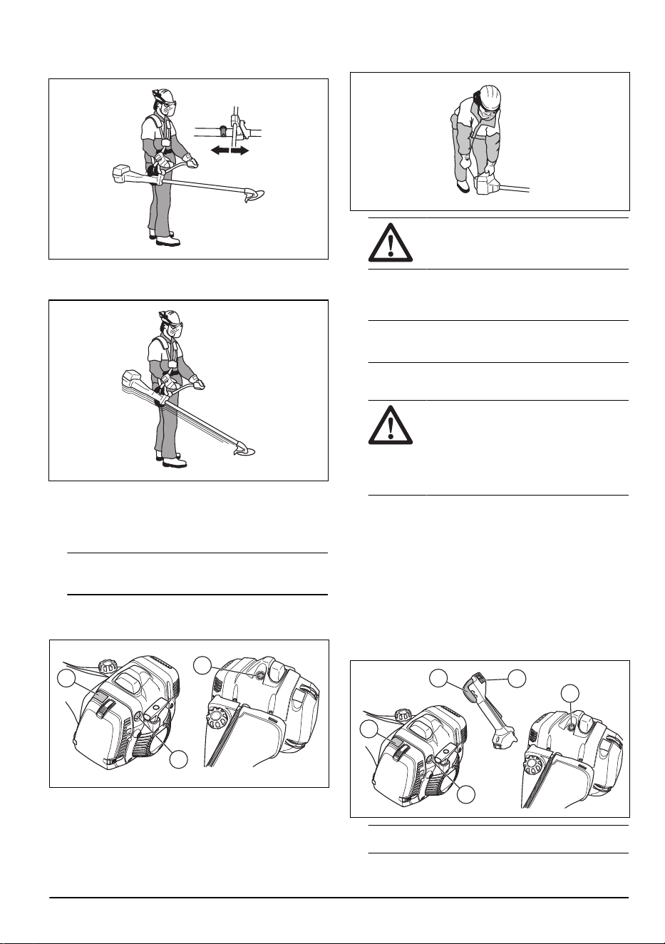
point. With correct balance, the risk of hitting stones if
you release the handlebar is decreased.
For grass clearing, the product is correctly balanced
when the blade is at cutting height near the ground.
To start a cold engine
1. Pull the choke control (A) up.
2. Push the decompression valve (B).
Note:
The decompression valve moves to the
initial position when the product starts.
3. Push the air purge bulb (C) about 6 times or fuel until
fuel starts to fill the bulb. It is not necessary to fill the
air bulb fully.
C
B
A
4. Hold the body of the product on the ground with your
left hand.
CAUTION: Do not step on the
product.
5. Pull the starter rope handle slowly until you feel
some resistance. When you feel resistance, pull the
starter rope handle quickly and with force.
Note: Do not twist the starter rope around your
hand.
6. Continue pull the starter rope handle until the engine
starts.
CAUTION: Do not pull the starter
rope to full extension and do not let go
of the starter rope handle. Release the
starter rope slowly. If you do not obey
these instructions it can cause damage
to the engine.
7. Set the choke control to the run position and apply
full throttle.
To start a warm engine (545F, 545FX,
545FXT)
1. Set the stop switch (A) to the start position.
2. Pull the choke control (B) up.
3. Set the throttle trigger (C) to the start position.
4. Push the air purge bulb (D) 10 times. It is not
necessary to fill the air purge bulb fully.
D
A
E
C
B
Note:
Do not use the decompression valve (E).
1018 - 013 - 14.12.2023 17
5. Pull the starter rope handle quickly and with force.
Pull the starter rope handle until the engine fires.
To start a warm engine (545FR,
545RX, 545RXT)
1. Set the stop switch (A) to the start position.
2. Push the throttle lockout (B) and the throttle trigger
(C).
3. Push the start throttle button (D) while you engage
the throttle trigger (C).
4. Release the throttle lockout and the throttle trigger.
5. Push the air purge bulb (E) 10 times. It is not
necessary to fill the air purge bulb fully.
E
D
B
F
A
C
Note: Do not use the decompression valve (F).
6. Pull the starter rope handle quickly and with force.
Pull the starter rope handle until the engine fires.
To stop the engine
• Move the stop switch to the stop position.
Heated handles
545FXT has heating elements in the handles. There is
an ON/OFF switch on the throttle handle. The heating
elements automatically keep a temperature of 70° when
the heat is on.
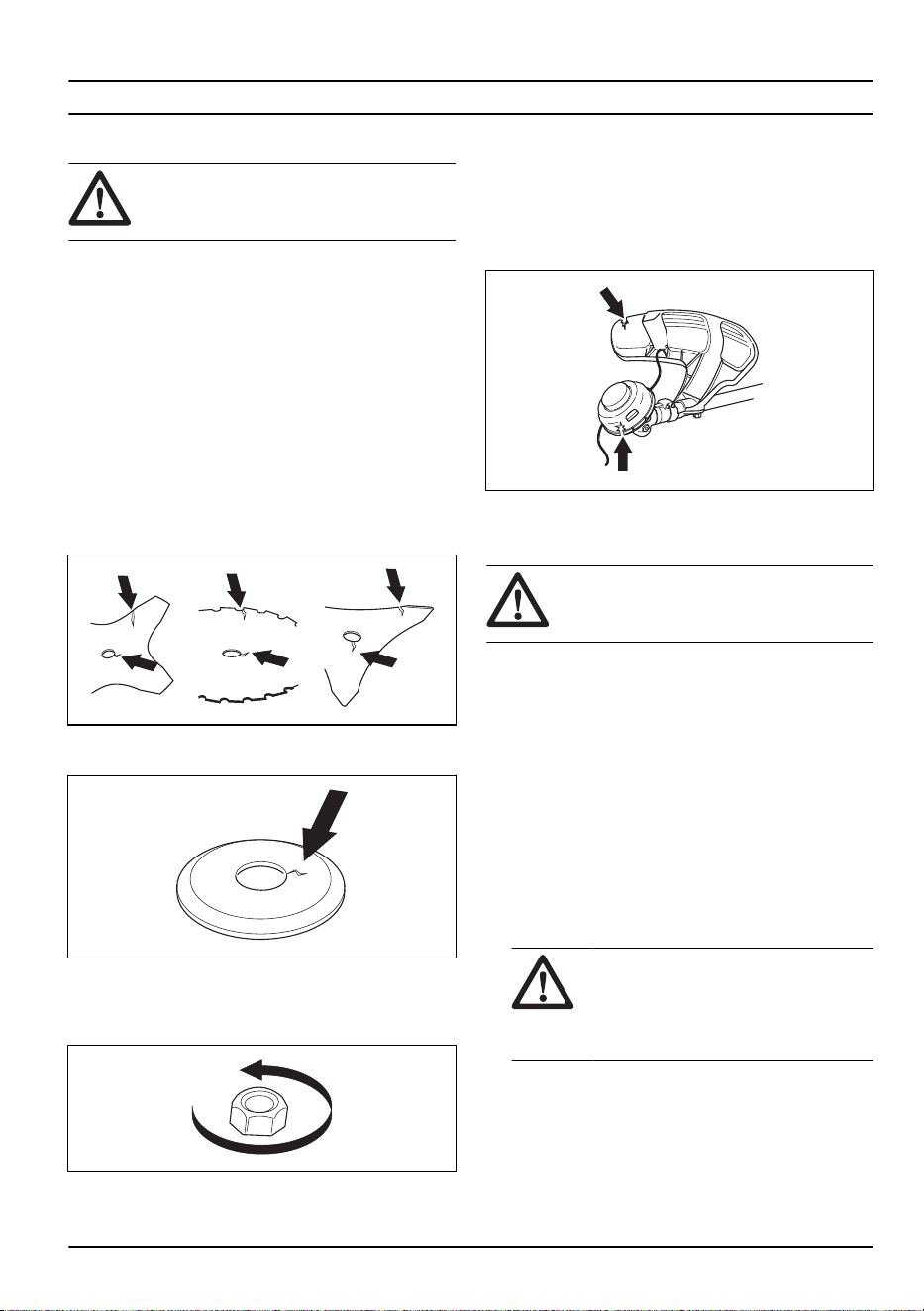
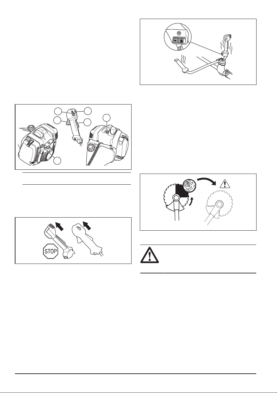
Blade thrust
A blade thrust is when the product moves to the side
quickly and with force. A blade thrust occurs when the
grass blade or saw blade hits or catches on an object
that cannot be cut. A blade thrust can eject the product
or operator in all directions. There is a risk of injury to
the operator and bystanders.
The risk increases in areas where it is not easy to see
the material that is cut.
Do not cut with the area of the blade that is shown in
black. The speed and movement of the blade can cause
blade thrust. The risk increases with the thickness of the
branch that is cut.
General work instructions
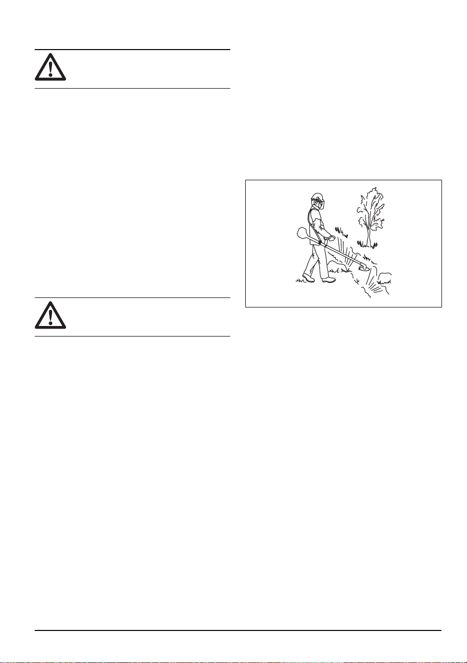
WARNING:
Be careful when you cut a
tree that is in tension. It can spring back to
its normal position before or after the cut and
hit you or the product, and cause injury.
• Clear an open space at one end of the work area,
and start the work from there.
18
1018 - 013 - 14.12.2023
• Move in a regular pattern across the work area.
• Move the product fully to the left and right, to clear a
width of 4–5 m on each turn.
• Clear a length of 75 m before you turn and go back.
Move the fuel can along with you as you continue.
• Move in a direction where you do not go across
ditches and obstacles more than necessary.
• Move in a direction where the wind makes the cut
vegetation fall in the cleared area.
• Move along slopes, not up and down.
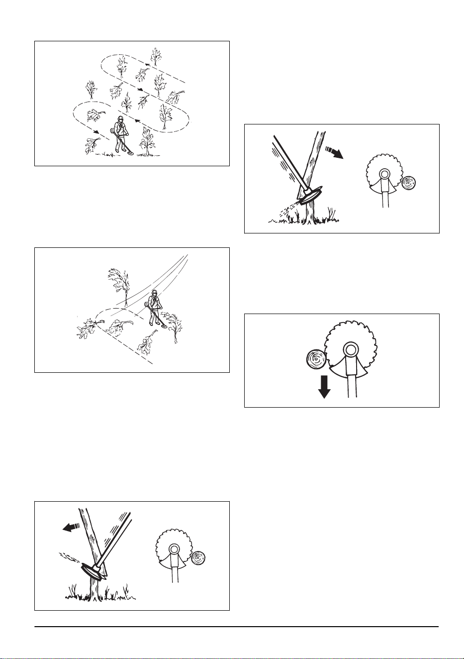
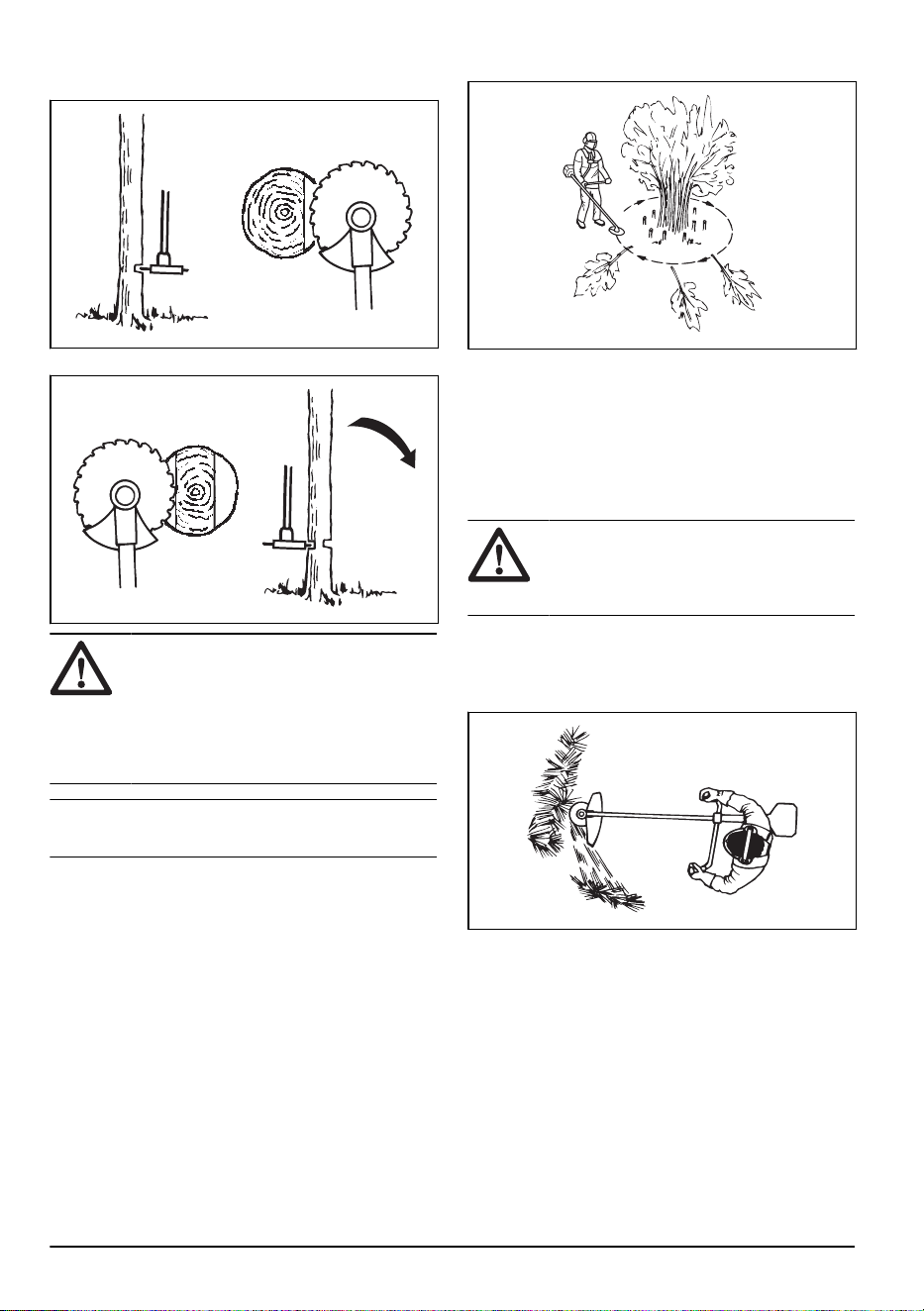
Forestry clearing with a saw blade
To fell a tree to the left
To fell to the left, push the bottom of the tree to the right.
1. Apply full throttle.
2. Put the saw blade against the tree as given in the
picture.
3. Tilt the saw blade and push it with force diagonally
down to the right. At the same time, push the tree
with the blade guard.
To fell a tree to the right
To fell to the right, push the bottom of the tree to the left.
1. Apply full throttle.
2. Put the saw blade against the tree as given in the
picture.
3. Tilt the saw blade and push it with force diagonally
up and to the right. At the same time, push the tree
with the blade guard.
To fell a tree forward
To fell forward, push the bottom of the tree rearward.
1. Apply full throttle.
2. Put the saw blade against the tree as given in the
picture.
3. Pull the saw blade forward with a fast movement.
To fell large trees
Large trees must be cut from 2 sides.
1. Examine in which direction the tree will fall.
2. Apply full throttle.
1018 - 013 - 14.12.2023
19
3. Do the first cut on the side of the tree to which it will
fall.
4. Cut through the tree from the other side.
CAUTION: If the saw blade becomes
blocked, do not pull the product with a
sudden movement. That can cause damage
to the saw blade, bevel gear, shaft or
handlebar. Release the handles, hold the
shaft with 2 hands and carefully pull the
product.
Note: Use more cutting pressure fo fell small trees.
Use less cutting pressure to fell large trees.
Brush cutting with a saw blade
To fell to the left, push the bottom of the tree to the right.
• Cut down thin trees and brush.
• Move the product from side to side.
• Cut many trees in one movement.
• For groups of thin trees:
a) Cut the outer trees high up.
b) Cut the outer trees to the correct height.
c) Cut from the center. If you cannot get access to
the center, cut the outer trees high up and let
them fall. This decreases the risk that the saw
blade becomes blocked.
Grass clearing with a grass blade
CAUTION: Do not use grass blades
and grass knives on wood. Use grass blades
and grass knives for long or heavy grass
only.
• Move the product from side to side.
• Start the movement from right to left when you cut.
Move the product to the right before you cut again.
• Cut with the left side of the grass blade.
• Angle the grass blade to the left to make the grass
fall in a line. This makes it easy to collect the grass.
• Keep a stable position with your feet apart.
• Move forward after each right movement and make
sure that you have a stable position again before you
cut again.
• Keep the support cup with a light pressure against
the ground to make sure that the grass blade does
not hit the ground.
• Obey these instructions to decrease the risk that cut
material winds around the grass blade:
a) Apply full throttle.
20
1018 - 013 - 14.12.2023
b) Do not move the grass blade through cut
material when you move the product from left to
right.
• Before you collect the cut material, stop the engine
and remove the product from the harness. Put the
product down on the ground.
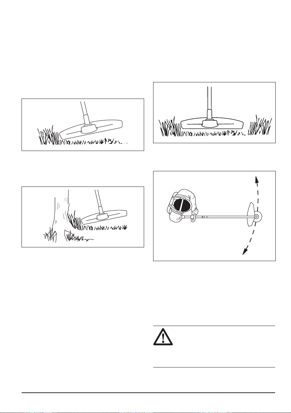
Grass trimming with a trimmer head
To trim the grass
1. Hold the trimmer head immediately above the
ground at an angle. Do not push the trimmer line
into the grass.
2. Decrease the length of the trimmer line by 10-12
cm / 4-4.75 in.
3. Decrease the engine speed to decrease the risk of
damage to plants.
4. Use 80 % throttle when you cut grass near objects.
To clear grass with a grass blade
1. Grass blades and grass cutters must not be used on
woody stems.
2. A grass blade is used for all types of tall or coarse
grass.
3. The grass is cut down with a sideways, swinging
movement, where the movement from right-to-left
is the clearing stoke and the movement from left-to-
right is the return stoke. Let the left-hand side of the
blade (between 8 and 12 o'clock) do the cutting.
4. if the blade is angled to the left when clearing grass,
the grass will collect in a line, which makes it easier
to collect, e.g. by raking.
5. Try to work rhythmically. Stand firmly with your feet
apart. Move forward after the return stoke and stand
firmly again.
6. Let the support cup rest lightly against the ground. It
is used to protect the blade from hitting the ground.
7. Reduce the risk of material wrapping around the
blade by always work at full throttle and avoid the
previously cut material during the return stoke.
8. Stop the engine, unclip the harness and place the
machine on the ground before you start to collect the
cut material.
To cut the grass
1. Make sure that the trimmer line is parallel to the
ground when you cut the grass.
2. Do not push the trimmer head to the ground. This
can cause damage to the product.
3. Move the product from side to side when you cut
grass. Use full speed.
To sweep the grass
The airflow from the rotating trimmer line can be used to
remove cut grass from an area.
1. Hold the trimmer head and the trimmer line parallel
to the ground and above the ground.
2. Apply full throttle.
3. Move the trimmer head from side to side and sweep
the grass.
WARNING:
Clean the trimmer head
cover each time you assemble new trimmer
line to prevent unbalance and vibrations in
the handles. Also do a check of the other
parts of the trimmer head and clean it if
necessary.
1018 - 013 - 14.12.2023 21

Maintenance
Introduction
WARNING: Before you do
maintenance, you must read and
understand the safety chapter.
For all servicing and repair work on the product, special
training is necessary. We guarantee the availability of
professional repairs and servicing. If your dealer is not
a service agent, speak to them for information about the
nearest service agent.
For more detailed information, refer to
www.husqvarna.com.
Maintenance schedule
Maintenance Daily Weekly Monthly
Clean the external surface. X
Examine the harness for damages. X
Examine the quick-release mechanism on the harness for damages and make
sure that it operates correctly.
X
Do a check of the throttle trigger lockout and the throttle trigger. Refer to
To do a
check of the throttle trigger lockout on page 6
.
X
Make sure that the cutting attachment does not rotate at idle speed. X
Do a check of the stop switch. Refer to
To do a check of the stop switch on page
7
.
X
Examine the cutting attachment guard for damages and cracks. X
Make sure that the saw bladeor grass bladeis attached correctly. Make sure
that the saw blade or grass blade is sharp and not damaged.
X
Examine the support flange for damages and cracks. Replace it if it is damaged. X
Examine the trimmer head for damages and cracks. Replace it if it is damaged. X
Examine the handle and the handlebar for damages and make sure that they are
attached correctly.
X
Tighten the locking screw fully for cutting attachments with a support cup. X
Tighten the locknut fully for cutting attachments with a locknut. X
Examine the transport guard for damage and make sure that it can be attached
correctly.
X
Examine the engine, the fuel tank and the fuel lines for leaks. X
Clean the air filter. Replace it if it is damaged. X
Tighten nuts and screws. X
Examine the starter and the starter rope for damages. X
Examine the vibration damping units for damages and cracks.
1
X
Examine the spark plug. Refer to
To examine the spark plug on page 27
. X
Clean the cooling system. X
1
Replace the vibration damping unit after each season or at a minimum of one time each year.
22 1018 - 013 - 14.12.2023
Maintenance Daily Weekly Monthly
Clean or replace the spark arrester screen. X
Clean the external surface of the carburetor and the area around it. X
Make sure that the bevel gear is filled to ¾ with grease. X
Clean or replace the spark arrester screen. Refer to
To do a check of the muffler
on page 8
.
X
Examine the fuel filter for contamination and the fuel hose for cracks and other
damages. Replace if it is necessary.
X
Examine all cables and connections. X
Examine the clutch, clutch springs and clutch drum for wear. Replace it if it is
necessary.
X
Replace the spark plug. X
Lubricate the drive shaft.
2
X
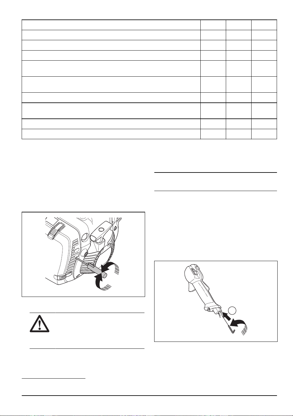
To adjust the idle speed
Your Husqvarna product is made to specifications that
decrease harmful emissions.
1. Make sure that the air filter is clean and the air filter
cover is attached before you adjust the idle speed.
2. Adjust the idle speed with the idle speed screw T
which is identified with "T" mark.
a) Turn the idle speed screw T clockwise until the
cutting attachment starts to rotate.
b) Turn the idle speed screw T counterclockwise
until the cutting attachment stops.
WARNING: If the cutting
attachment does not stop when you
adjust the idle speed, speak to your
servicing dealer. Do not use the product
until it is correctly adjusted or repaired.
3. The idle speed is correct when the engine operates
smoothly in all positions. The idle speed must be
below the speed when the cutting attachment starts
to rotate.
Note: Refer to
Technical data on page 30
for the
recommended idle speed.
To adjust the start throttle speed
(545FR, 545RX, 545RXT)
1. Apply idle speed to the product.
2. Push the start throttle lock. Refer to
Product
overview on page 2
.
3. If the start throttle speed is less than 4000 rpm,
turn theadjuster screw (A) clockwise. When the
cutting attachment starts to rotate, turn the adjuster
screw(A) 1/2 turn clockwise.
A
4. If the start throttle speed is more than 6500 rpm, turn
the adjuster screw (A) counterclockwise. When the
cutting attachment starts to rotate, turn the adjuster
screw (A) 1/2 turn.
2
At an interval of 3 months.
1018 - 013 - 14.12.2023 23
To clean the muffler
WARNING: The muffler gets very hot
during and after operation, also at idle
speed. Risk of fire and burn injuries.
WARNING: A used muffler/spark
arrester and spark arrester mounting
face may contain deposits of combustion
particles on the surfaces that may be
carcinogenic. To avoid skin contact and
inhalation of such particles when cleaning
and/or servicing the spark arrester, make
sure you always:
• wear gloves;
• clean and/or service in a well ventilated
area;
• do not use pressurized air to clean the
spark arrester screen;
• use a steel brush and brush away from
your body when cleaning the spark
arrester.
1. If the muffler on your product has a spark arrester
screen, clean it weekly with a steel brush. Replace
the spark arrester screen if it is damaged.
CAUTION: A blocked spark arrester
screen causes the engine to become too hot
and results in damage to the cylinder and
piston.
CAUTION: If the spark arrester screen
is frequently blocked, let your service agent
examine the muffler.
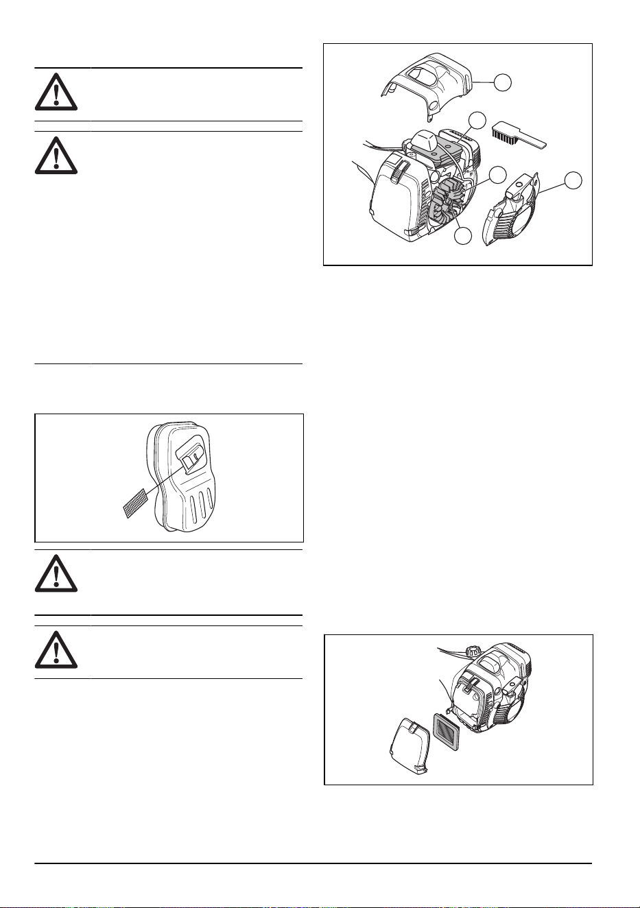
To clean the cooling system and starter
pawls
The cooling system includes:
• The cylinder cover (A)
• The cooling fins on the cylinder (B)
• The fins on the flywheel (C)
• The air intake on the starter (D)
• The starter pawls (E) that are found on the flywheel
D
E
C
B
A
Clean the cooling system weekly or more frequently if it
is necessary.
1. Remove the starter cover and the cylinder cover.
2. Clean the cooling system with a brush.
3. Examine the starter pawls and area around them for
dirt.
4. Clean around the starter pawls with a brush, to make
sure that they can move freely.
Air filter
Remove dust and dirt from the air filter to keep it clean
and prevent these problems:
• Carburetor malfunctions.
• Problems when you start the product.
• Loss of engine power.
• Increased wear to engine parts.
• Too much fuel consumption.
To do a check of a paper air filter
1. Set the choke control in the choke position.
2. Open the 3 snap locks that holds the air filter cover.
3. Remove the air filter cover.
4. Remove the air filter.
5. Examine and clean the air filter housing with a brush.
24
1018 - 013 - 14.12.2023
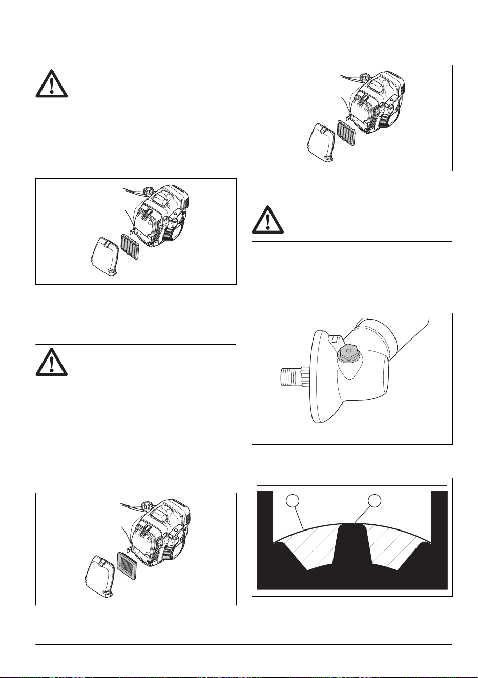
6. Examine the air filter. Replace the air filter if it is
dirty or damaged. Only use approved Husqvarna air
filters.
CAUTION: Do not bend or fold the air
filter as this can cause damage to the air
filter. Replace a damaged air filter.
To clean a nylon air filter
1. Set the choke control in the choke position.
2. Open the 3 snap locks that holds the air filter cover.
3. Remove the air filter cover.
4. Remove the air filter.
5. Examine and clean the air filter housing with a brush.
6. Examine the air filter. Clean the air filter with warm
soap water. Replace the air filter if it cannot be
fully cleaned or if it is damaged. Only use approved
Husqvarna air filters.
CAUTION:
Do not bend or fold the air
filter as this can cause damage to the air
filter. Replace a damaged air filter.
To change from a paper air filter to a nylon air
filter
Use a nylon air filter when the temperature is below 5°C/
41°F.
1. Set the choke control in the choke position.
2. Open the 3 snap locks that holds the air filter cover.
3. Remove the air filter cover.
4. Remove the air filter.
5. Examine and clean the filter housing with a brush.
6. Examine the filter. Replace the filter if it is dirty or
damaged.
7. Install the nylon air filter correctly.
8. Attach the air filter cover.
9. Close the 3 snap locks that holds the air filter cover.
CAUTION: Do not bend or fold the filter
as this can cause damage to the filter. A
damaged filter must always be replaced.
To lubricate the bevel gear
1. Remove the cutting equipment.
2. Put the product with the grease plug at its highest
position.
3. Remove the grease plug.
4. Look into the grease plug hole and turn the drive
shaft. The grease level (A) must be in level with the
top of the gear cogs (B).
A B
1018 - 013 - 14.12.2023
25
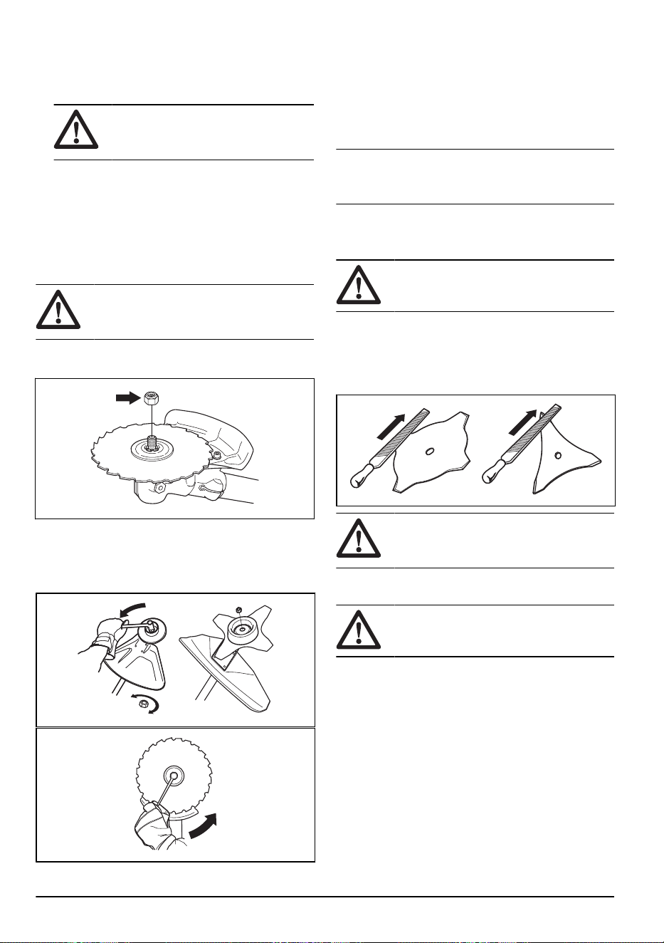
5. If the grease level is too low fill the bevel gear with
Husqvarna bevel gear grease. Fill slowly and turn
the drive shaft as you apply the bevel gear grease,
stop at the correct level (B).
CAUTION: An incorrect quantity of
grease can cause damage to the bevel
gear.
6. Install the grease plug.
Drive shaft
Lubricate the drive shaft at an interval of 3 months. Let
a service agent help you if you are not sure about the
procedure.
To attach and remove the locknut
WARNING: Stop the engine, use
protective gloves and be careful around the
sharp edges of the cutting attachment.
Use the locknut to attach some types of cutting
attachments. The locknut has a left thread.
• Use a socket wrench with a shaft that is sufficiently
long to let you keep your hand behind the cutting
attachment guard. The arrow in the illustration shows
the area where you can safely operate the socket
wrench.
• To attach, tighten the locknut in the opposite
direction to how the cutting attachment rotates.
• To remove the locknut, turn it in the same direction
as how the cutting attachment rotates.
• Keep count when you remove and attach the
locknut. Replace the locknut after approximately 10
times.
Note: Make sure that you can not turn the locknut by
hand. Replace the locknut if the nylon lining does not
have a resistance of a minimum of 1.5 Nm.
To sharpen the grass knife and grass
blade
WARNING: Stop the engine. Use
protective gloves.
• To sharpen the grass knife or grass blade correctly,
refer to the instructions that come with the cutting
attachment.
• Sharpen all edges equally to keep the balance.
• Use a single-cut flat file.
WARNING: Always discard a blade
that is damaged. Do not try to make a bent
or twisted blade straight and use it again.
To sharpen the saw blade
WARNING: Stop the engine. Use
protective gloves.
• To sharpen the blade correctly, refer to the
instructions that come with the blade.
26
1018 - 013 - 14.12.2023
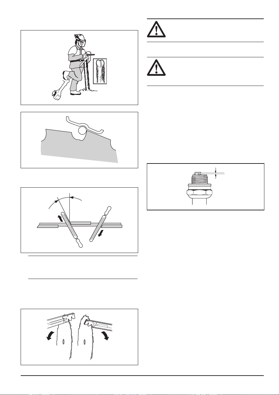
• Make sure that the product and blade has sufficient
support when you sharpen it.
• Use a 5.5 mm round file with a file holder.
• Hold the file at an angle of 15°.
• Sharpen one tooth of the saw blade to the right and
the next tooth to the left, see the illustration.
15˚
Note: Sharpen the edges of the teeth with a flat
file if the blade is heavily worn. Continue to sharpen
with a round file.
• Sharpen all edges equally to keep the blade
balanced.
• Adjust the blade set to 1 mm with the recommended
setting tool. Refer to the instructions that come with
the blade.
WARNING:
Always discard a blade
that is damaged. Do not try to make a bent
or twisted blade straight and use it again.
To examine the spark plug
CAUTION: Always use the
recommended spark plug type. Incorrect
spark plug type can cause damage to the
product.
• Examine the spark plug if the engine is low on
power, is not easy to start or does not operate
correctly at idle speed.
• To decrease the risk of unwanted material on the
spark plug electrodes, obey these instructions:
a) Make sure that the idle speed is correctly
adjusted.
b) Make sure that the fuel mixture is correct.
c) Make sure that the air filter is clean.
• If the spark plug is dirty, clean it and make sure that
the electrode gap is correct, refer to
Technical data
on page 30
.
• Replace the spark plug if it is necessary.
Winter use
When you operate the product in cold and snowy
weather you can experience problems such as:
• The engine temperature becomes to low.
• Ice occurs on the air filter or carburetor.
To remove ice from the air filter and carburetor
• Put a cover on a part of the air intake of the starter
engine to increase the temperature during operation.
• Use the heat from the muffler to increase the
temperature of the air to the carburetor.
To adjust the product for cold environments
If the temperature is 5°C/41°F or colder, adjustments are
necessary to prevent operation problems.
1018 - 013 - 14.12.2023
27
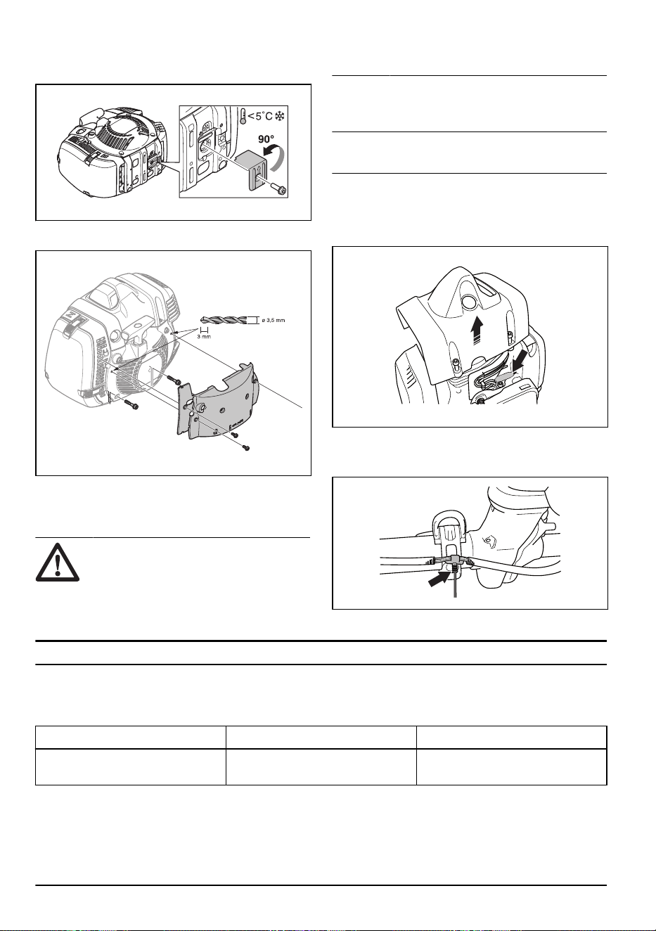
• Attach the air duct as shown in the illustration. Make
sure that the arrow points in the direction of the
winter mode symbol.
• If you operate the product in snow or below 5°C/
41°F, attach a cover on top of the starter.
• Replace the air paper filter with a nylon air filter that
is approved for operation in winter conditions. Refer
to,
To change from a paper air filter to a nylon air
filter on page 25
.
CAUTION:
Do not operate the product
at temperatures of more than 5°C/41°F if
it is adjusted for winter mode. The engine
becomes too hot and can be damaged.
Make sure that the winter mode adjustments
are removed before you operate the product
at temperatures more than 5°C/41°F.
To lubricate the wire
545FXT
Note: The wire is lubricated at the factory. Lubricate
the wire when it is necessary.
1. Remove the protective cover.
2. Remove the cylinder cover to get access to the
rubber bellows on the wire.
3. Make sure that the rubber bellows does not expand.
4. Remove the plug on the grease nipple.
5. Use antifreeze spray with a 2 mm spray tube. Spray
with short intervals.
6. Attach the cylinder cover and the protective cover.
Troubleshooting
The engine does not start
Check Possible cause Procedure
Stop switch. The stop switch is in the stop posi-
tion.
Let an approved servicing dealer re-
place the stop switch.
28 1018 - 013 - 14.12.2023

Check Possible cause Procedure
Starter pawls. The starter pawls cannot move free-
ly.
Remove the starter cover and clean
around the starter pawls. Refer to
To
clean the cooling system and starter
pawls on page 24
.
Let an approved servicing dealer
help you.
Fuel tank. Incorrect fuel type. Drain the fuel tank and fill with cor-
rect fuel.
Carburetor Incorrect adjustment of the idle
speed
Adjust the idle speed with the idle
speed screw T.
Spark plug. The spark plug is dirty or wet. Make sure that the spark plug is dry
and clean.
The spark plug electrode gap is in-
correct.
Clean the spark plug. Make sure that
the electrode gap is correct. Make
sure that the spark plug has a su-
pressor.
Refer to
Technical data on page 30
for correct electrode gap.
The spark plug is loose. Tighten the spark plug.
Fuel filter The fuel filter is clogged. Replace the fuel filter.
The engine starts but stops again
Check
Possible cause Procedure
Fuel tank Incorrect fuel type. Empty the fuel tank and fill it with cor-
rect fuel.
Fuel filter The fuel filter is clogged. Replace the fuel filter.
Carburetor The idle speed is not correctly adjus-
ted.
Adjust the idle speed with the idle
speed screw T.
Air filter The air filter is clogged. Clean the air filter.
Transportation, storage and disposal
Transportation and storage
• Let the product cool before transportation or storage.
• Remove the spark plug cap before long-term
storage.
• Attach the product during transportation. Make sure
that it cannot move.
• Make sure that there is no risk of fuel leaks, fuel
fumes, sparks or flames during transportation and
storage.
• Attach the transport guard during transportation and
storage.
• Clean and do servicing on the product before long-
term storage.
Disposal
• Obey the local recycling requirements and applicable
regulations.
• Discard all chemicals, such as oil or fuel, at a service
center or at an applicable disposal location.
1018 - 013 - 14.12.2023 29

• When the product is no longer in use, send it to
a Husqvarna dealer or discard it at a recycling
location.
Technical data
Technical data
545FR 545RX 545RXT
Engine
Cylinder displacement, cm
3
45.7 45.7 45.7
Idle speed, rpm 2700 2700 2700
Speed of output shaft, rpm 10100 8800 8800
Max. engine power, according to ISO 8893,
kW/hp @ rpm
2.1/2.8 @ 9000 2.1/2.8 @ 9000 2.1/2.8 @ 9000
Catalytic converter muffler No No No
Ignition system
Spark plug NGK CMR6H NGK CMR6H NGK CMR6H
Electrode gap, mm 0.5 0.5 0.5
Fuel
Fuel tank capacity, l/cm
3
0.9/900 0.9/900 0.9/900
Weight
Weight, kg 8.2 8.9 8.7
Noise emissions
3
Sound power level, measured dB (A) 113 115 115
Sound power level, guaranteed L
WA
dB (A) 114 117 117
Sound levels
4
Equivalent sound pressure level at the operator’s ear, measured according to EN ISO 11806 and ISO 22868, dB(A):
Equipped with trimmer head (original) 100 100 100
Equipped with grass blade (original) 100 100 100
Equipped with saw blade (original) 100 – –
Vibration levels
5
Equivalent vibration levels (a
hv,eq
) at handles, measured according to EN ISO 11806 and ISO 22867, m/s
2
:
3
Noise emissions in the environment measured as sound power (LWA) in conformity with EC directive
2000/14/ EC. Reported sound power level for the machine has been measured with the original cutting
attachment that gives the highest level. The difference between guaranteed and measured sound power
is that the guaranteed sound power also includes dispersion in the measurement result and the variations
between different machines of the same model according to Directive 2000/14/EC.
4
Reported data for equivalent sound pressure level for the machine has a typical statistical dispersion (stand-
ard deviation) of 1 dB(A).
5
Reported data for equivalent vibration level has a typical statistical dispersion (standard deviation) of 1 m/s
2
.
30 1018 - 013 - 14.12.2023

545FR 545RX 545RXT
Equipped with trimmer head (original), left/
right
3.6/3.8 3.2/2.9 3.2/2.9
Equipped with grass blade (original), left/right 3.3/3.0 2.9/2.4 2.9/2.4
Equipped with saw blade (original), left/right 2.8/3.2 – –
Technical data
545FX 545FXT 545F
Engine
Cylinder displacement, cm
3
45.7 45.7 45.7
Idle speed, rpm 2700 2700 2700
Speed of output shaft, rpm 9600 9600 9600
Max. engine power, according to ISO 8893,
kW/hp @ rpm
2.2/2.9 @ 9000 2.2/2.9 @ 9000 2.0/2.7 @ 9000
Catalytic converter muffler No No No
Ignition system
Spark plug NGK CMR6H NGK CMR6H NGK CMR6H
Electrode gap, mm 0.5 0.5 0.5
Fuel
Fuel tank capacity, l/cm
3
0.9/900 0.9/900 0.9/900
Weight
Weight, kg 8.2 8.4 8.4
Noise emissions
6
Sound power level, measured dB (A) 113 113 113
Sound power level, guaranteed L
WA
dB (A) 114 114 114
Sound levels
7
Equivalent sound pressure level at the operator’s ear, measured according to EN ISO 11806
and ISO 22868, dB(A):
Equipped with trimmer head (original) – – –
Equipped with grass blade (original) – – –
Equipped with saw blade (original) 99 99 99
6
Noise emissions in the environment measured as sound power (L
WA
) in conformity with EC directive
2000/14/EC. Reported sound power level for the machine has been measured with the original cutting
attachment that gives the highest level. The difference between guaranteed and measured sound power
is that the guaranteed sound power also includes dispersion in the measurement result and the variations
between different machines of the same model according to Directive 2000/14/EC.
7
Reported data for equivalent sound pressure level for the machine has a typical statistical dispersion (stand-
ard deviation) of 1 dB(A).
1018 - 013 - 14.12.2023 31

545FX 545FXT 545F
Vibration levels
8
Equivalent vibration levels (a
hv,eq
) at handles, measured according to EN ISO 11806 and ISO 22867, m/s
2
:
Equipped with trimmer head (original), left/
right
– – –
Equipped with grass blade (original), left/right – – –
Equipped with saw blade (original), left/right 2.0/3.2 2.0/3.2 2.7/3.2
Accessories
Accessories for 545FR
Approved accessories
Accessory type Cutting attachment guard, art. no.
Centre hole in blades/knives, Ø 25.4
mm
Output shaft thread M12
Grass blade/grass knife Multi 255-3 (Ø 255, 3 teeth) 537 28 85-01 / 544 46 43-05
Multi 275-4 (Ø 275, 4 teeth) 537 28 85-01 / 544 46 43-05
Multi 300-3 (Ø 300 3 teeth) 537 28 85-01 / 544 46 43-05
Saw blade Maxi XS 200-22 (Ø 200, 22 teeth) 537 31 09-01
Scarlet 200-22 (Ø 200, 22 teeth) 537 31 09-01
Plastic blades Tricut Ø 300 mm (Separate blades
have part number 531 01 77-15)
537 28 85-01 / 544 46 43-05
Trimmer head Trimmy S II (Ø 2.4–3.3 mm cord) 503 95 43-01 / 544 46 43-05
Auto 55 (Ø 2.7-3.3 mm cord) 503 95 43-01 / 544 46 43-05
T45x (Ø 2.7–3.3 mm cord) 503 95 43-01 / 544 46 43-05
Support cup Fixed
Shredder blade 544 02 65-02
Accessories for 545F 545FX, 545FXT
Approved accessories
Accessory type Cutting attachment guard, art. no.
Centre hole in blades/knives, Ø 25.4
mm
Output shaft thread M12
8
Reported data for vibration level has a typical statistical dispersion (standard deviation) of 1 m/s
2
.
32 1018 - 013 - 14.12.2023

Approved accessories Accessory type Cutting attachment guard, art. no.
Grass blade/grass knife Multi 255-3 (Ø 255, 3 teeth) 537 29 74-01 / 544 46 43-05
Multi 275-4 (Ø 275, 4 teeth) 537 29 74-01 / 544 46 43-05
Multi 300-3 (Ø 300 3 teeth) 537 29 74-01 / 544 46 43-05
Saw blade Maxi 200-26 (Ø 200, 26 teeth) 574 53 26-01
Scarlet 200-22 (Ø 200, 22 teeth) 574 53 26-01
Scarlet 225-24 (Ø 225, 24 teeth) 574 50 67-02
Maxi 225-24T BACHO (Ø 225, 24
teeth)
574 50 67-02
Plastic blades Tricut Ø 300 mm (Separate blades
have part number 531 01 77-15)
537 29 74-01 / 544 46 43-05
Trimmer head Trimmy S II (Ø 2.4–3.3 mm cord) 537 29 73-01 / 544 46 43-05
Auto 55 (Ø 2.7-3.3 mm cord) 537 29 73-01 / 544 46 43-05
T45x (Ø 2.7–3.3 mm cord) 537 29 73-01 / 544 46 43-05
T55x (Ø 2.7–3.3 mm cord) 537 29 73-01 / 544 46 43-05
Support cup Fixed
Accessories for 545RX, 545RXT
Approved accessories
Accessory type Cutting attachment guard, art. no.
Centre hole in blades/knives, Ø 25.4
mm
Output shaft thread M12
Grass blade/grass knife Multi 255-3 (Ø 255, 3 teeth) 537 28 85-01 / 544 46 43-05
Multi 275-4 (Ø 275, 4 teeth) 537 28 85-01 / 544 46 43-05
Multi 300-3 (Ø 300 3 teeth) 537 28 85-01 / 544 46 43-05
Saw blade Maxi XS 200-22 (Ø 200, 22 teeth) 537 31 09-01
Scarlet 200-22 (Ø 200, 22 teeth) 537 31 09-01
Plastic blades Tricut Ø 300 mm (Separate blades
have part number 531 01 77-15)
537 28 85-01 / 544 46 43-05
Trimmer head Trimmy S II (Ø 2.4–3.3 mm cord) 503 95 43-01 / 544 46 43-05
Auto 55 (Ø 2.7–3.3 mm cord) 503 95 43-01 / 544 46 43-05
T45x (Ø 2.7–3.3 mm cord) 503 95 43-01 / 544 46 43-05
Support cup Fixed
1018 - 013 - 14.12.2023 33

Declaration of Conformity
EU Declaration of conformity
We, Husqvarna AB, SE-561 82 Huskvarna, Sweden, tel:
+46-36-146500, declare on our sole responsibility that
the product:
Description Brush cutters
Brand Husqvarna
Type / Model 545FR, 545FX, 545FXT, 545RX, 545RXT, 545F
Identification Serial numbers dating from 2016 and onwards
complies fully with the following EU directives and
regulations:
Regulation Description
2006/42/EC "relating to machinery"
2014/30/EU "relating to electromagnetic compatibility"
2000/14/EC "relating to the noise emissions in the environment"
2011/65/EU "on the restriction of the use of certain hazardous substances in electrical and electronic
equipment "
and that the following standards and/or technical
specifications are applied: EN ISO 12100:2010, EN
ISO 14982:2009, EN IEC 63000:2018, EN ISO
11806-1:2011
SMP Svensk Maskinprovning AB, Box 4053, SE-904
03 Umeå, Sweden has performed a voluntary type
examination according to annex IX of 2006/42/EC.
Certificate Number: SEC/11/2294 - 545FR,
SEC/11/2293 - 545RX, RXT, SEC/11/2292 - 545F,
545FX, 545FXT.
SMP Svensk Maskinprovning AB has also verified
agreement with annex V of the council's directive
2000/14/EC.
For information relating to noise emissions, refer to
Technical data on page 30
.
Huskvarna, 2023-07-01
Stefan Holmberg, Development Manager of Husqvarna
AB
Responsible for technical documentation
34 1018 - 013 - 14.12.2023

UK Declaration of conformity
We, Husqvarna AB, SE-561 82 Huskvarna, Sweden, tel:
+46-36-146500, declare on our sole responsibility that
the product:
Description Brush cutters
Brand Husqvarna
Type / Model 545FR, 545FX, 545FXT, 545RX, 545RXT, 545F
Identification Serial numbers dating from 2022 and onwards
complies fully with the following UK regulations:
Description
The Supply of Machinery (Safety) Regulations 2008
Electromagnetic Compatibility Regulations 2016
The Noise Emission in the Environment by Equipment for use Outdoors Regulations 2001, Schedule 8
The Restriction of the Use of Certain Hazardous Substances in Electrical and Electronic Equipment Regulations
2012
and that the following standards and/or technical
specifications are applied: EN ISO 12100:2010, EN
ISO 14982:2009, EN IEC 63000:2018, EN ISO
11806-1:2011
For information relating to noise emissions, refer to
Technical data on page 30
.
Huskvarna, 2023-07-01
Stefan Holmberg, Development manager of Husqvarna
AB
Responsible for technical documentation
UK Importer:
Husqvarna UK Ltd
Preston Road, Co. Durham
DL5 6UP
1018 - 013 - 14.12.2023 35
1
3
8
7
4 5
2
Tri Cut
36 1018 - 013 - 14.12.2023
1
2
3
4
5
6
7
8
9
35-50 NM
~ 15 cm
6'
"Click"
~ 3,5 m
11'
7,0 m
23'
2,4-3,3 mm
.095"-.130"
12 cm
5"
Trimmy SII
1018 - 013 - 14.12.2023 37
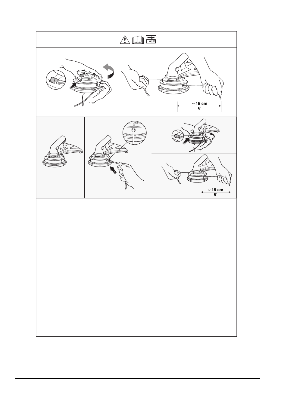
Trimmy SII
1 2 3
4
38 1018 - 013 - 14.12.2023
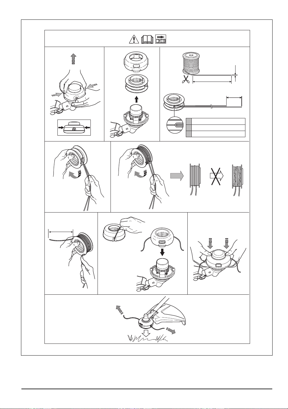
A
2,7 - 4,0 mm / .105 - .160"
B
8 m / 26’
C
15 cm / 5.9"
1
2
3
5
6
7
9
4
8
6"
15 cm
B
C
A
T55x
"Click"
1018 - 013 - 14.12.2023 39
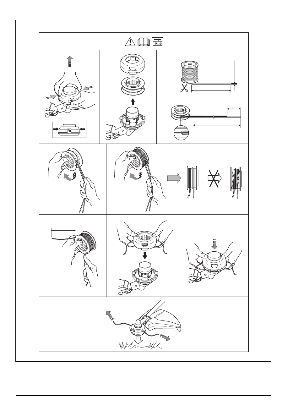
"Click"
1
2
3
5
6
7
9
10 m
32'
4
8
4,3 m
14'
2,7-3,3 mm
.106-.13"
10 cm
4"
6"
15 cm
T45, T45x
40 1018 - 013 - 14.12.2023

1018 - 013 - 14.12.2023 41

42 1018 - 013 - 14.12.2023

1018 - 013 - 14.12.2023 43

www.husqvarna.com
Original instructions
1142998-26
2023-12-21