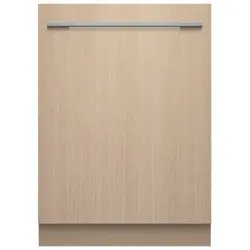
INTEGRATED
DW60UT4I2, DW60U4I2, DW60U2I2, DW60U4HI2 and
DW60UT4HI2 models
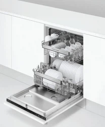
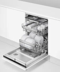
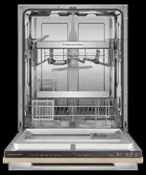
BUILT-UNDER DISHWASHER
INSTALLATION GUIDE
NZ AU UK IE

3
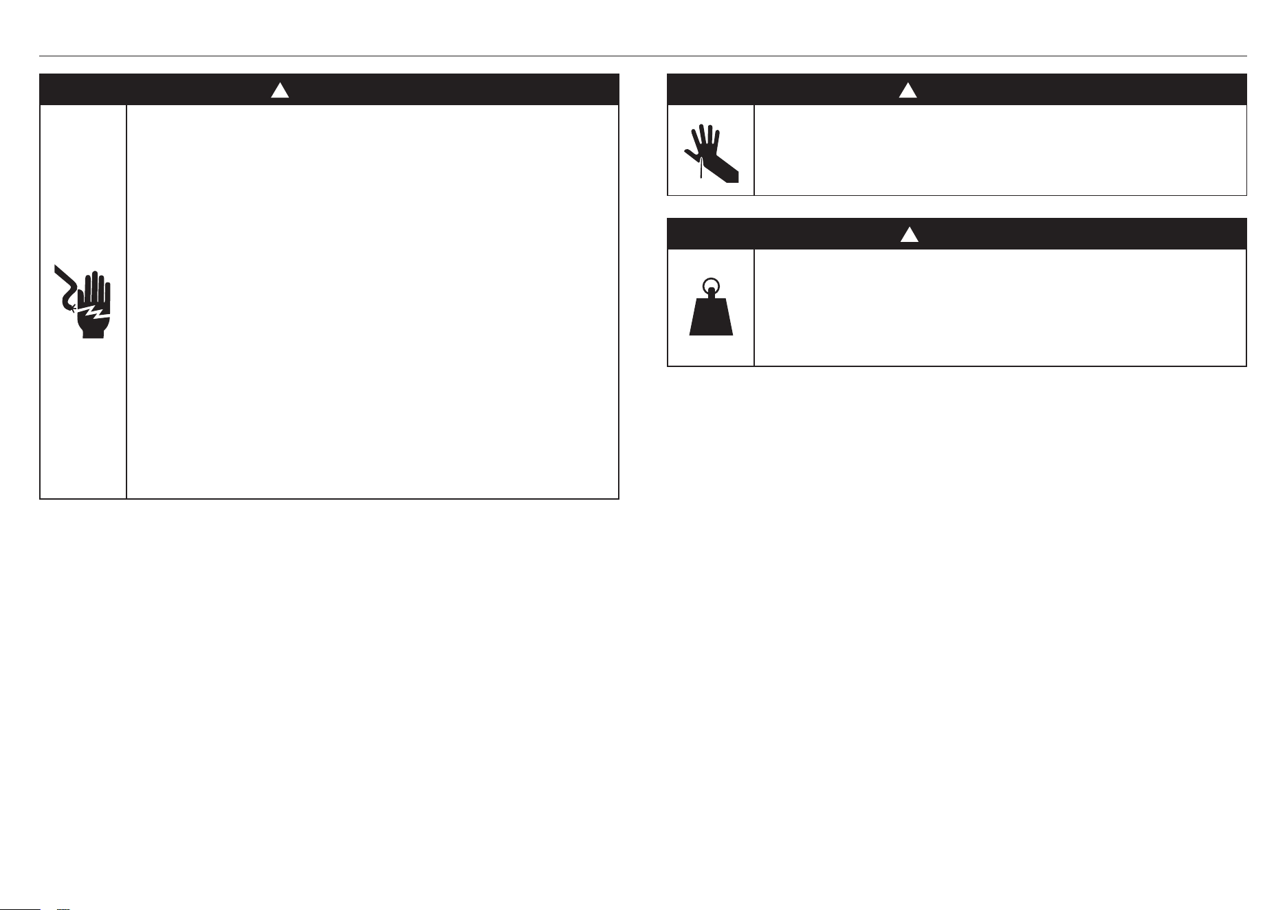
SAFETY AND WARNINGS
!
WARNING!
Electric Shock Hazard
Failure to follow this advice may result in
electrical shock or death.
• This appliance must be earthed. This appliance
has a cord with an equipment-earthing conductor
and an earthing plug. The plug must be plugged
into an appropriate outlet that is installed and
earthed in accordance with all local regulations.
• WARNING – Improper connection of the
equipment-earthing conductor can result in a
risk of electric shock. Check with a qualified
electrician or service technician if you are unsure
if the appliance is properly earthed.
• Do not modify the power supply plug provided
with the appliance. If a different outlet is required
have it installed by a qualified electrician. Do not
use an extension cord, adapter plug or multi-box.
!
WARNING!
420-630 lb
190-285 kg
Weight Hazard
Failure to follow this advice may result in
damage or personalinjury.
• Do not attempt to lift this product unassisted.
!
WARNING!
Cut Hazard
Failure to use caution could result in injury.
• Take care – panel edges are sharp.

4
SAFETY AND WARNINGS
SAVE THESE INSTRUCTIONS
The models shown in this installation guide may not be available in all markets and are subject to
change at any time. For current details about model and specification availability in your country,
please go to our website www.fisherpaykel.com or contact your local Fisher&Paykel dealer.
WARNING!
To reduce the risk of fire, injury to persons or damage when using the appliance, follow the
important safety instructions listed below. Read all the guidance before using the appliance.
Servicing
z
Do not repair or replace any part of the appliance unless specifically recommended in
this guide. All other servicing should be undertaken by a Fisher & Paykel trained and
supported service technician or qualified person.
Installation
z
Ensure all water connections are turned OFF. It is the responsibility of the plumber and
electrician to ensure that each installation complies with all Codes and Regulations.
z
The dishwasher MUST be installed to allow for future removal from the enclosure if
service is required.
z
The switched power outlet must be outside the dishwasher cavity, so that it is
accessible after installation.
z
This dishwasher is manufactured for indoor use only.
z
Care should be taken when the appliance is installed or removed to reduce the
likelihood of damage to the power supply cord and hoses.
z
If the dishwasher is to be relocated from one installation to another it must be kept
upright to avoid damage from water spillage.
z
Make sure only new hoses are used for connection (supplied with the dishwasher). Old
hoses should not be reused.
z
Failure to install the dishwasher correctly could invalidate any warranty or
liability claims.
z
Ensure the dishwasher is placed between cabinetry. Failure to do so may result in an
unstable product, which may cause damage or injury.
z
Do not operate this appliance if it is damaged, malfunctioning, partially disassembled
or has missing or broken parts, including a damaged power supply cord or plug.
z
Do not store or use petrol, or other flammable vapours and liquids in the vicinity of the
dishwasher.
z
Connect to a properly rated, protected and sized power supply circuit to avoid
electrical overload.
z
Make sure that the power supply cord is located so that it will not be stepped on,
tripped over or otherwise subject to damage or stress.
z
Do not install or store the dishwasher where it will be exposed to temperatures below
freezing or exposed to weather.
z
Do not use an extension cord or a portable electrical outlet device (e.g. multi-socket
outlet box) to connect the dishwasher to the power supply.
z
This appliance must be earthed. In the event of a malfunction or breakdown, earthing
will reduce the risk of electric shock by providing a path of least resistance for
electric current.
z
This appliance is equipped with a cord having an equipment-earthing conductor and
an earthing plug. The plug must be plugged into an appropriate outlet that is installed
and earthed in accordance with all local codes and ordinances.
z
EARTHING INSTRUCTIONS - This appliance must be connected to a earthed metal,
permanent wiring system, or an equipment-earthing conductor must be run with
the circuit conductors and connected to the equipment-earthing terminal or lead on
the appliance.
z
Ensure the product is not plugged in when fitting custom panels.
z
Installation of custom panels requires basic mechanical and electrical skills.
z
Installation must comply with your local building and electricity regulations.
z
Failure to install the custom panels correctly could invalidate any warranty or
liability claims.
z
Be sure to leave these Instructions with the Customer.
z
At the completion of the dishwasher installation, the Installer must perform the
Final Checklist.
z
Remove all packaging materials supplied with the dishwasher.
z
If the product is installed in a motor vehicle, boat or similar mobile facility, you must bring
the vehicle, boat or mobile facility containing the product to the service shop at your
expense or pay the service technician's travel to the location of the product.
5
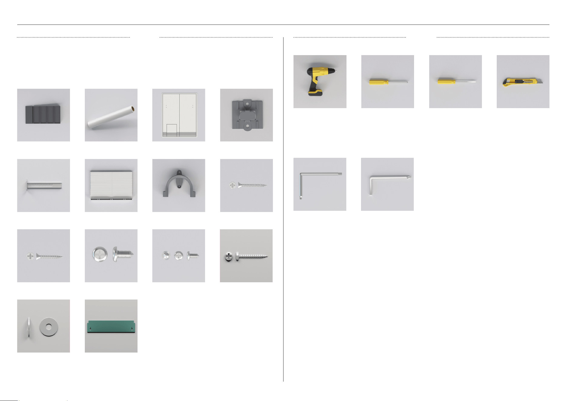
COMPONENTS REQUIRED
PARTS
TOOLS
z
Keep all packing materials until the unit has been inspected.
z
Inspect the product to ensure there is no shipping damage. If any damage is detected
contact the dealer or retailer you bought the product from to report the damage.
z
Fisher & Paykel is not responsible for shipping damage.
Spacers (4)
Toe kick brackets (2)
4.0 x 25mm screws (4)
*Quantity may differ between models | ** Not required for DW60U2I2 models
Moisture protection tape (1)
4.0 x 13 screws (9)
Door panel template (1)
Drain hose support (1) 3.9 x 38mm screws (6)*
Sliding bracket (1)
Exit vent (1)**
Supplied
Powered driver
4mm / 6mm Allen Key 4mm / Phillips Allen Key**
Cross-head screw driver Flat-head screw driver Box cutter
Not suppliedNot supplied
Supplied
3.5 x 11mm screws (2)** 4.2 x 50mm screws (2)
Washer (2) Sound seal (1)
6
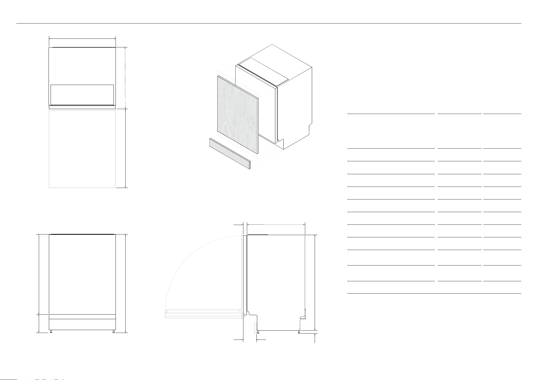
PRODUCT DIMENSIONS
Actual product dimensions may vary by ± 2 mm
PRODUCT DIMENSIONS
DW60UT4I2
DW60UT4HI2
(MM)
DW60U4I2
DW60U2I2
DW60U4HI2
(MM)
A Overall height* 857 - 917 820 - 880
B Overall width** 597 597
C Overall depth** 554 554
D Height of chassis 857 820
E Depth of chassis 521 521
F Height of feet* 0 - 60 0 - 60
G Depth of toe kick recess 120 120
H Depth of inner door** 33 33
I Height from top of chassis
to bottom of inner door
719 683
J Height from to bottom of
inner door to floor*
138 138
K Depth of door opening** 676 639
*depending on adjustment of levelling feet
**excluding custom panel and handle
PLAN
FRONT
ISO
PROFILE
a
i
j
d
f
g
c
k
b
e
h
7
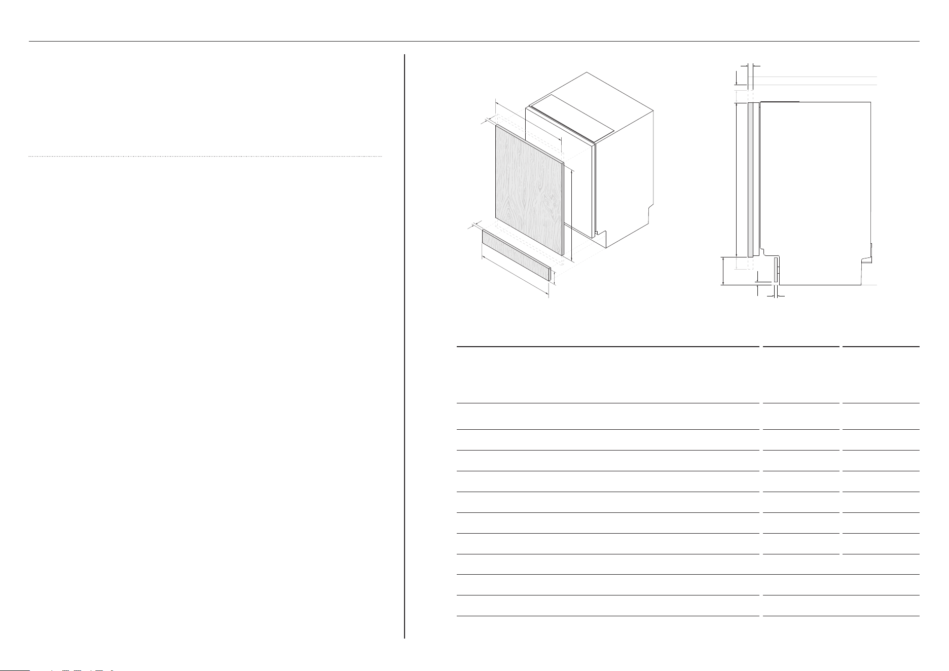
CUSTOM PANEL DIMENSIONS
Material specifications
z
Maximum weight of door panels must not exceed 9kg (including handle)
z
The panel should be adequately sealed to withstand moisture (50°C @
80% RH). The back and sides of the panel should be completely sealed
with a waterproof vapour barrier, such as polyurethane, to prevent damage.
z
Installation outside these specifications may result in condensation on
cabinetry surfaces.
Toe kick considerations
z
Depending on the desired toe kick recess depth and door panel extension,
the toe kick panel height may need to be adjusted to allow adequate
door swing.
CUSTOM PANEL CONSIDERATIONS
DW60UT4I2
DW60UT4HI2
(MM)
DW60U4I2
DW60U2I2
DW60U4HI2
(MM)
A Minimum height of custom door panel for full coverage of the
inner door
714 677
B Minimum door panel width 596 596
C Door panel depth 16 - 25 16 - 25
D Distance from base of door panel to floor 65 - 200 65 - 200
E Toe kick panel height 65 - 200 65 - 200
F Minimum width of custom toe kick panel* 596 596
G Minimum toe kick panel depth** 16 16
H Minimum clearance between top of door panel and benchtop 2 2
Weight of door panel (including handle) 4 - 9kg 4 - 9kg
*Continuous toe kick installations are possible and detailed on page 15
**if using supplied toe kick mounting screws. Panel can be fixed via screwing or gluing to the supplied mounting bracket.
ISO PROFILE
a
d
h
c
a
e
f
bc
g
g
8
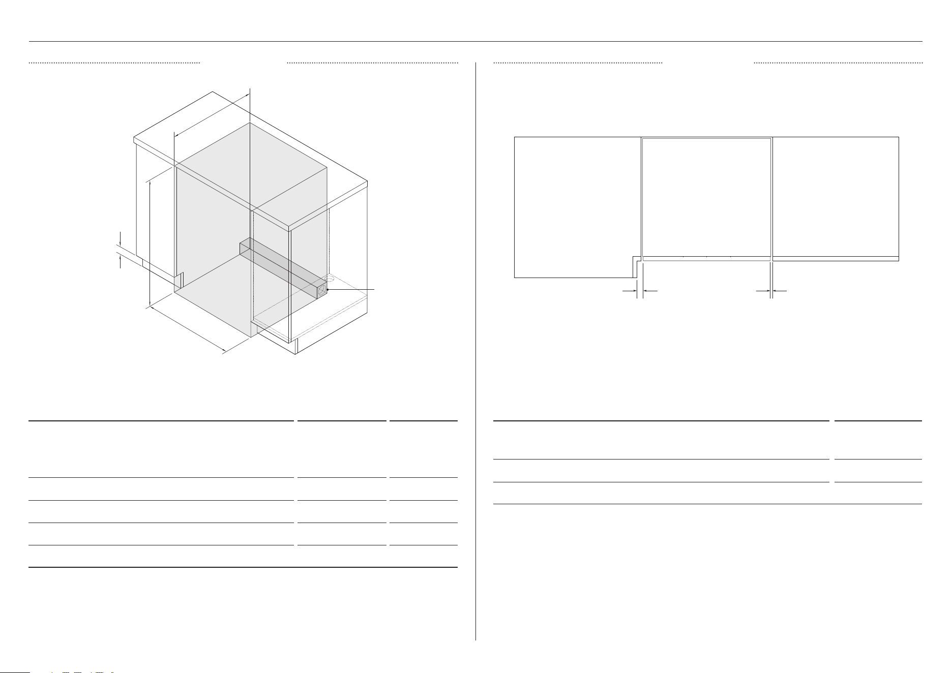
CABINETRY
DIMENSIONS CLEARANCES
CABINETRY DIMENSIONS
DW60UT4I2
DW60UT4HI2
(MM)
DW60U4I2
DW60U2I2
DW60U4HI2
(MM)
A Minimum inside height* 857 820
B Minimum inside width 600 600
C Minimum overall depth** 580 580
D Height of toe kick area 65 - 200 65 - 200
*depending on adjustment of levelling feet
**including 19mm door panels on adjacent cabinetry
***For more information on service requirements, refer to 'Plumbing & electrical considerations' and 'Cabinetry preparation'.
CABINETRY CLEARANCES MM
A Minimum clearance to adjacent cupboard door 2
B Minimum clearance to corner cupboard 13
B A
ISOMETRIC
PLAN
A
d
B
C
Connections can
be located in an
adjacent cabinet
on either side of
the dishwasher***
9
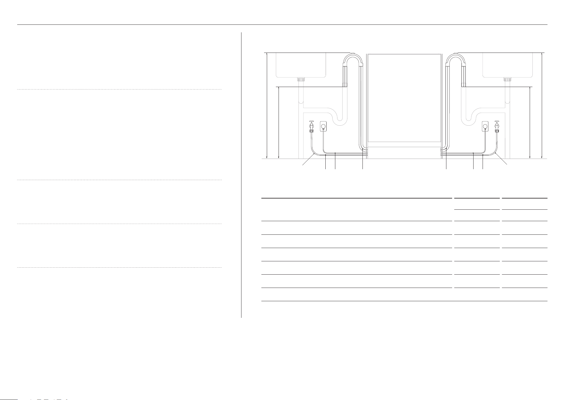
PLUMBING & ELECTRICAL CONSIDERATIONS
Hose and cord lengths
z
Your services can be installed to either the left-hand or right-hand side
of the product in an adjacent cabinet. Refer to 'Cabinetry preparation'
for service access requirements.
z
The drain hose should not extend more than 4m. A longer drain hose will
cause reduced performance.
Water connection
z
The dishwasher should not be connected to a water system where there
is no temperature control, unless the system is fitted with a suitable
tempering valve.
z
The dishwasher must not be connected to an undersink high-pressure
push-through hot water system, as damage to the system will result.
z
Maximum water temperature: 60°C
z
3/4 BSP connector water inlet hose
z
Ensure water connection complies with local plumbing regulations.
Water pressure
z
0.03-1MPa
Electrical requirements
z
230V, 50Hz, 10A
Anti-flood protection
z
This dishwasher has anti-flood protection, which will stop the water
flowing in the event of a leak within the machine.
SERVICE DIMENSION
LEFT SIDE RIGHT SIDE
MM MM
A Length of drain hose 1980 1650
B Length of power cord* 950 1450
C Length of inlet hose 1450 1300
D Distance from floor to top of hose support 750 – 883 750 – 883
E Minimum distance from floor to end of drain hoses** 500 500
F Minimum inlet hose radius 200 200
*excluding plug
**standpipe install illustrated. Distance is the same for all plumbing installs.
abc a b c
f
f
e e
dd
10
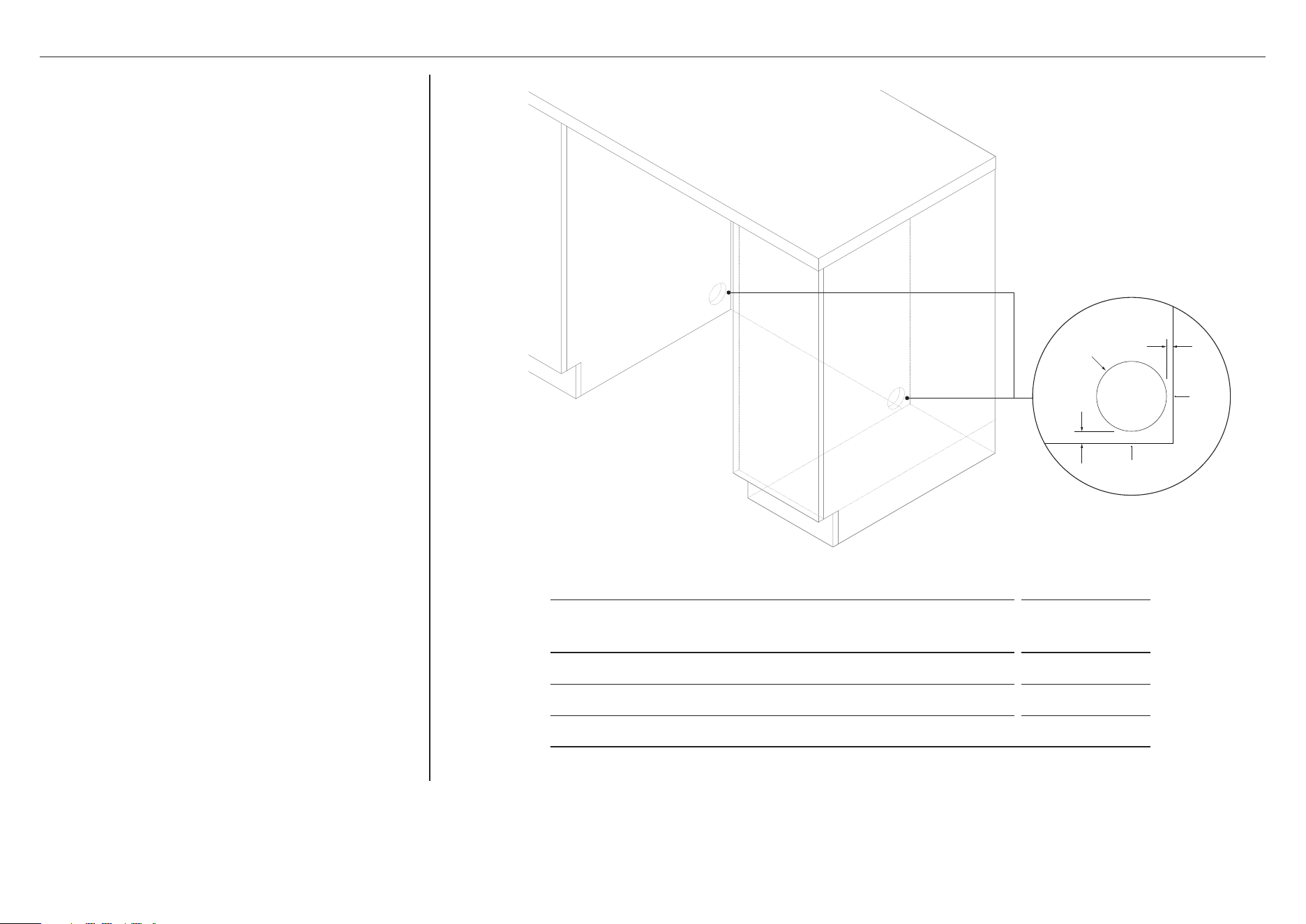
SERVICE ACCESS
SERVICE HOLE DIMENSIONS MM
A Maximum distance between rear of cavity and service hole* 15
B Maximum distance between floor and service hole** 0 - 50
C Minimum diameter of service hole 70
*based on a cabinetry depth of 580mm
**depending on adjustment of levelling feet
REAR
WALL
FLOOR
PROFILE
A
B
C
z
We recommend locating the service holes on
either side of the Dishwasher as shown.
z
If the holes are created through wood, ensure the
edges are smooth and rounded
z
If the holes are created through metal, ensure an
edge protector is fitted.
11
CABINETRY PREPARATION
1
2
3
Ensure all minimum cabinetry and
service specifications have been met
and that all services will be accessible
after installation.
Ensure cabinetry floor is free from
bumps and obstructions that could
prevent the Dishwasher from sliding into
the cavity.
Align the supplied moisture protection
tape to the cabinetry as shown.
Ensure this area is free of debris
before carefully applying the tape to
the surface.
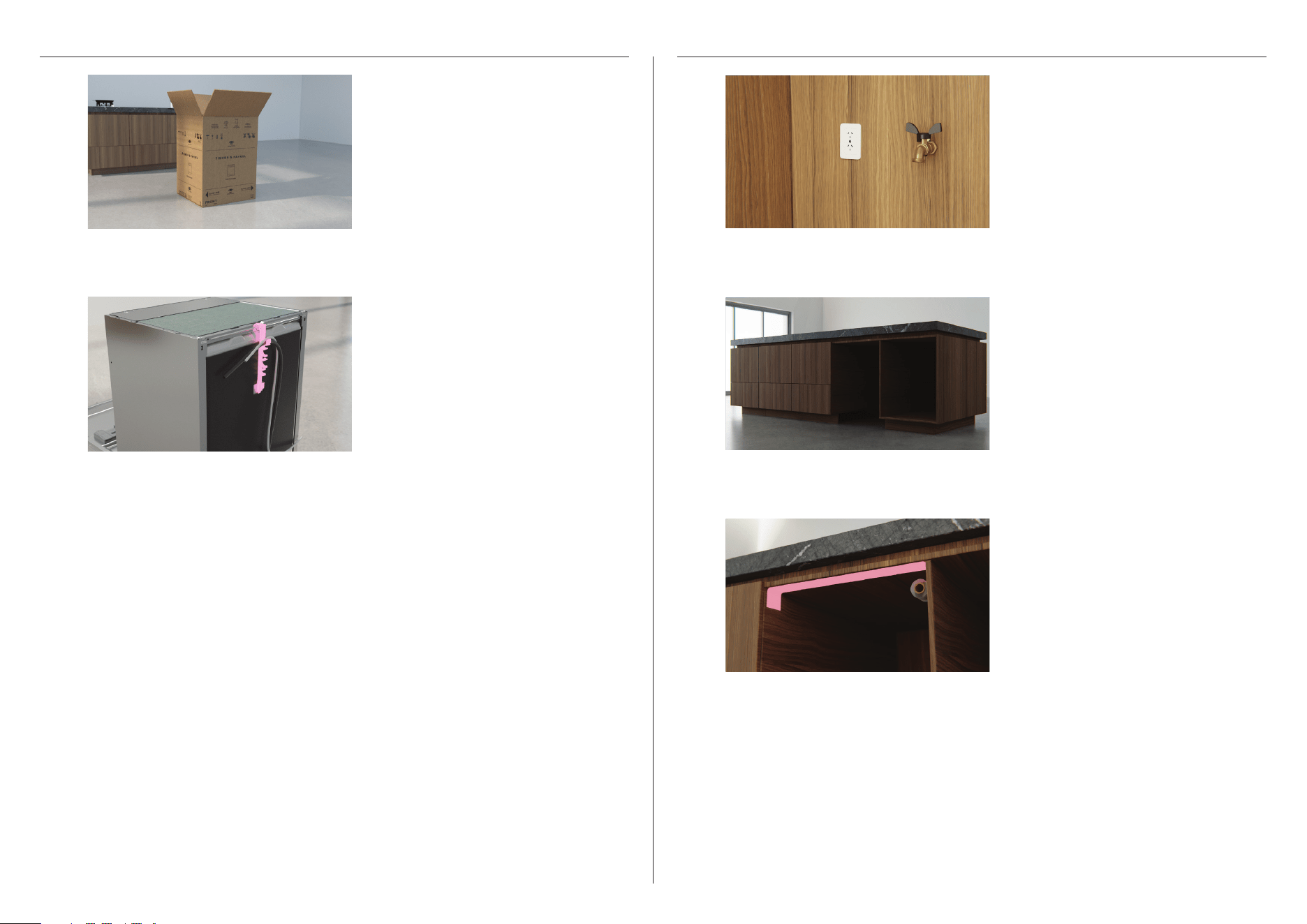
UNPACK PRODUCT
1
2
Remove the install kit, any internal
packaging, all rubber bands and all tape.
Cut straps, lift carton off product and
remove the top cap.
Dispose of packaging responsibly.
12
PUSH INTO CAVITY
1
2
3
4
Remove both screw covers before
partially pushing the product into the
cavity, pulling the hoses through as you
push to avoid crushing or twisting them.
Take care not to bend the legs.
Push the product from the outside
edges to avoid door damage.
Check the product sits level within
the cavity.
If required, the rear middle leg can be
adjusted from the front of the product
using a 5mm Allen key.
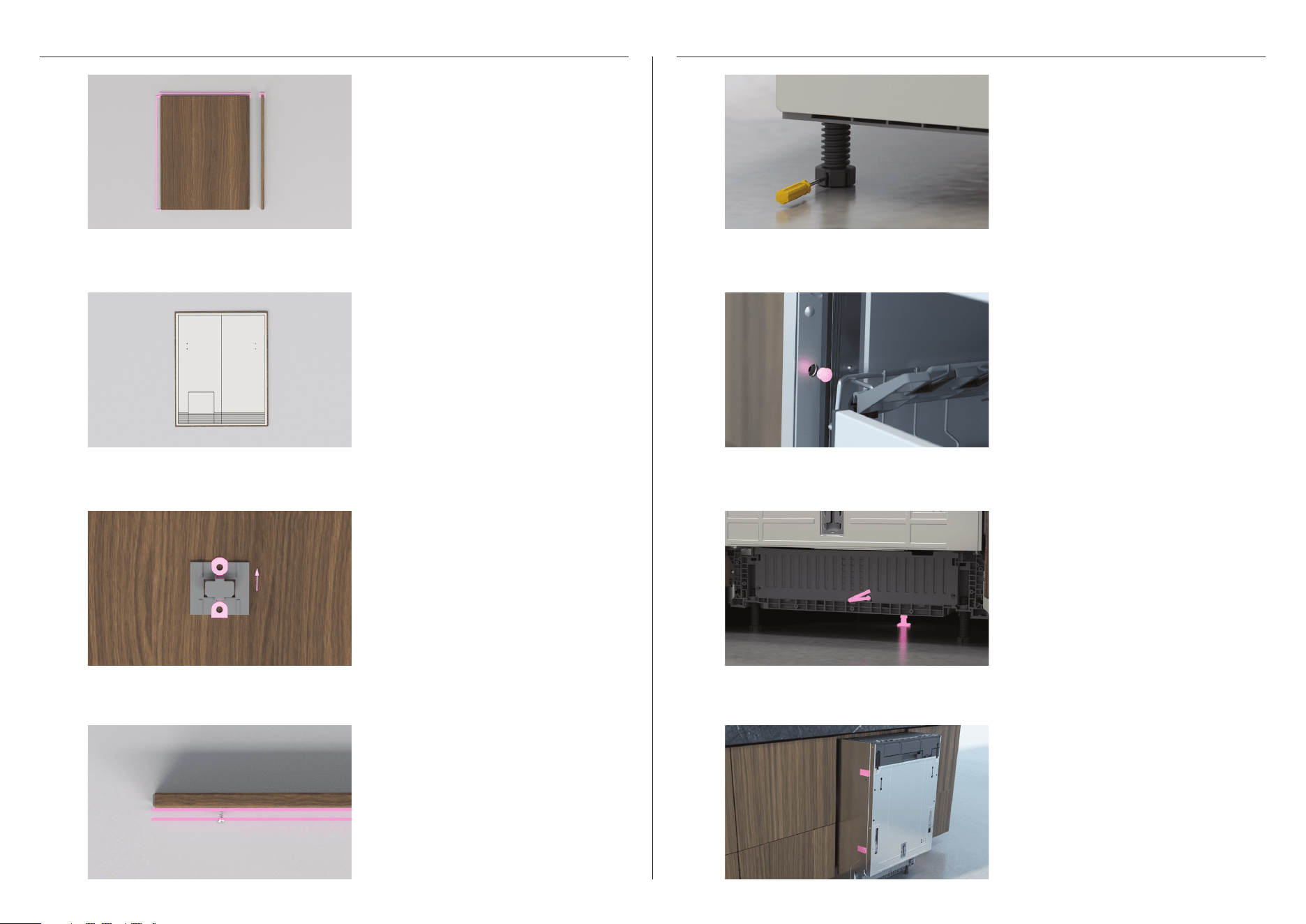
DOOR PANEL PREP
1
2
3
4
Using the template as a guide, pre-drill
all holes into the panel.
Ensure the sliding bracket is oriented
correctly before securing it to the panel.
Loosely fit both 16mm Philips hanging
screws onto the door panel. Ensure
there is a minimum space of 3 mm
between the screw-head and the panel.
Ensure door panel meets all
specifications.
Select desired spacer width and cut
to size. Remove adhesive and fit two
spacers to each side of the product.
Spacers allow product to be installed
without distorting the side walls. If gap
between the product and cabnety is too
large, a custom spacer may be required.
Push the product into the cavity from
the outside edges.
Unscrew the rear legs to the desired
under bench height, using a flat bladed
screwdriver adjust the front legs so the
product is level. Do not adjust the rear
middle leg yet.
13
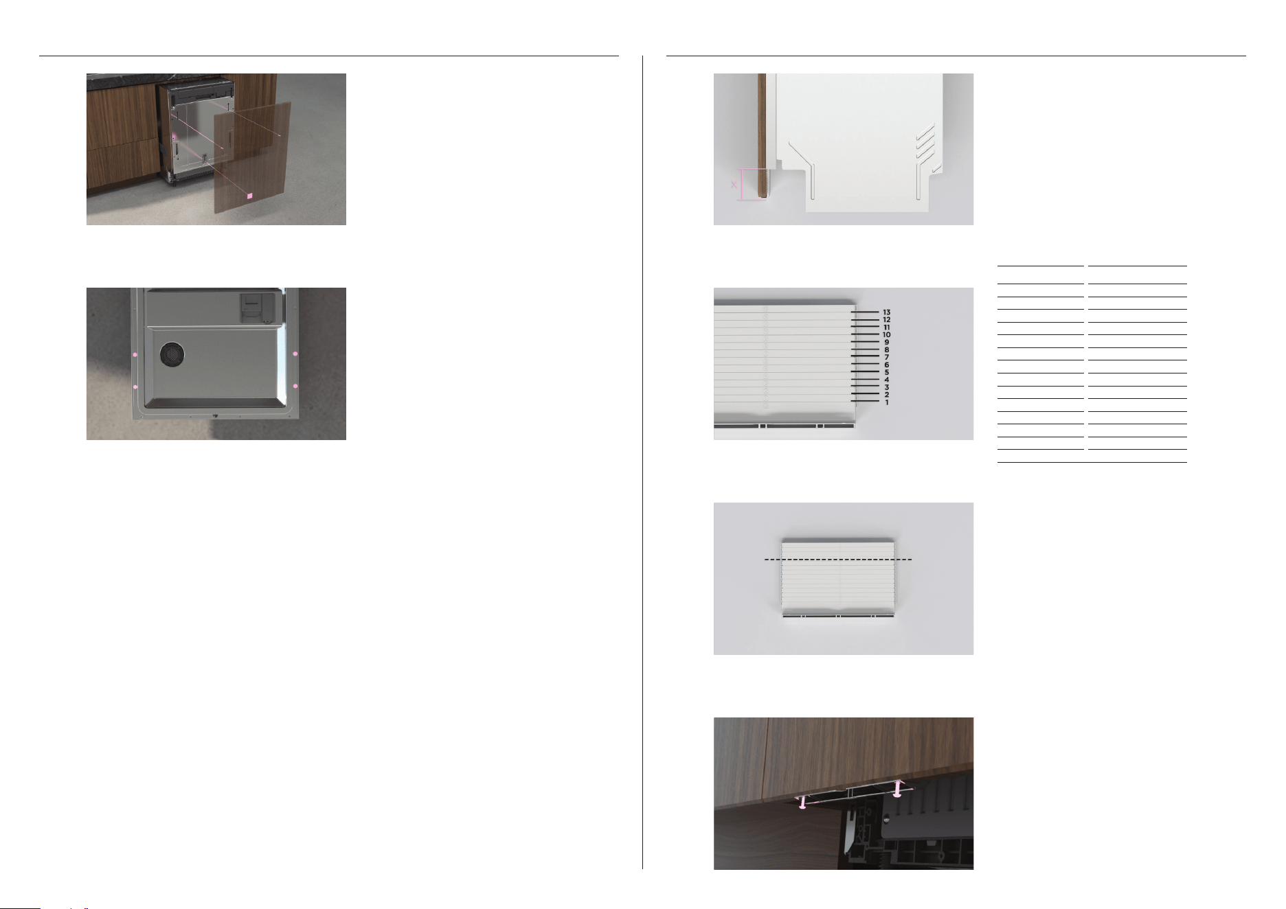
SECURE DOOR PANEL FIT EXIT VENT*
1 1
2 2
3
4
Align door panel to surrounding
cabinetry. Open door and secure panel
to product using 4 x screws.
On a protected surface, carefully cut
the vent at the desired location.
Slot the exit vent into the product and
secure using two 3.5x11mm screws.
Align the door panel to the product.
Slot slider bracket and upper screws
into place. Slide the panel upwards to
lock into place.
Measure the custom panel overhang
from the base of the inner door.
Refer to the table below for the
recommended cut location.
CUT LOCATION OVERHANG (MM)
0
0
1
0
2
0 - 5
3
5 - 12
4
13 - 19
5
20 - 26
6
27 - 33
7
34 - 40
8
41 - 47
9
48 - 54
!0
55 - 61
!1
62 - 68
!2
69 - 75
!3
76 - 82
* Not required for DW60U2I2 models
14
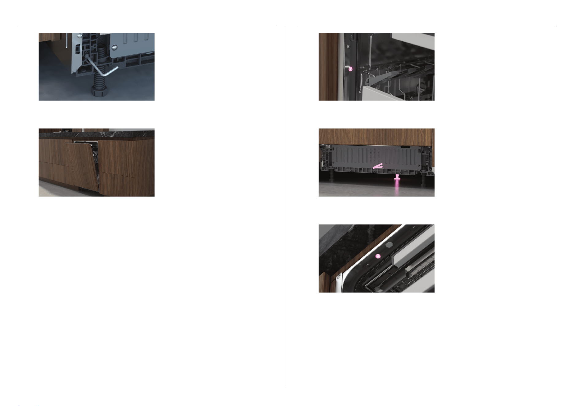
BALANCE DOOR SECURE TO CAVITY
1
Use a 4mm Allen key to adjust the
door tension. Rotate clockwise
to increase tension, rotate
counterclockwise to decrease tension.
Ensure both sides are adjusted evenly.
1
2
3
If needed, adjust the Dishwasher within
the cavity before tightly securing in
place. Replace the screw covers.
2
Open the door at a 45° angle and
ensure it holds. If the door does not stay
open, repeat the above step.
Loosely fit the 4.0 x 25mm screws on
each side. Do not over-tighten.
Overtightening could cause the sides
of the product to bow preventing the
door seal to function correctly resulting
in water leakage.
Secure to benchtop using the 4.0
x 25mm screws if possible. Do not
over-tighten.
Overtightening could cause the top
of the product to bow preventing the
door latch function.

15
INSTALL SOUND SEAL & TOE KICK
CUSTOM TOE KICK PANEL
CONTINUOUS TOE KICK PANEL
FIT SOUND SEAL
1
1
1
2
2
2
3
4
Ensure brackets are oriented correctly
before fitting to the panel using 2 x
screws per bracket.
Fit panel to surrounding cabinetry
Ensure door swing is unobstructed
before securing the seals using the
provided washers and 4.2 x 50mm
screws.
Align the brackets to the slots on the
product and slide into place.
Mark the pilot hole locations for each
bracket. Measure the centre of the
panel and mark 237mm to each side.
To determine the height of the
brackets, measure the height of the
lowest bracket hole against the toe
kick panel.
Align toe kick to product and ensure
all door swing clearances have
been met.
Align both sound seal sheets to the
base of the dishwasher. If required,
trim excess felt.
Measure the toe kick depth:
Use Z to determine which tooth to
bend back on each toe kick bracket.
x y z
-
=
toe kick recess panel thickness toe kick depth
16
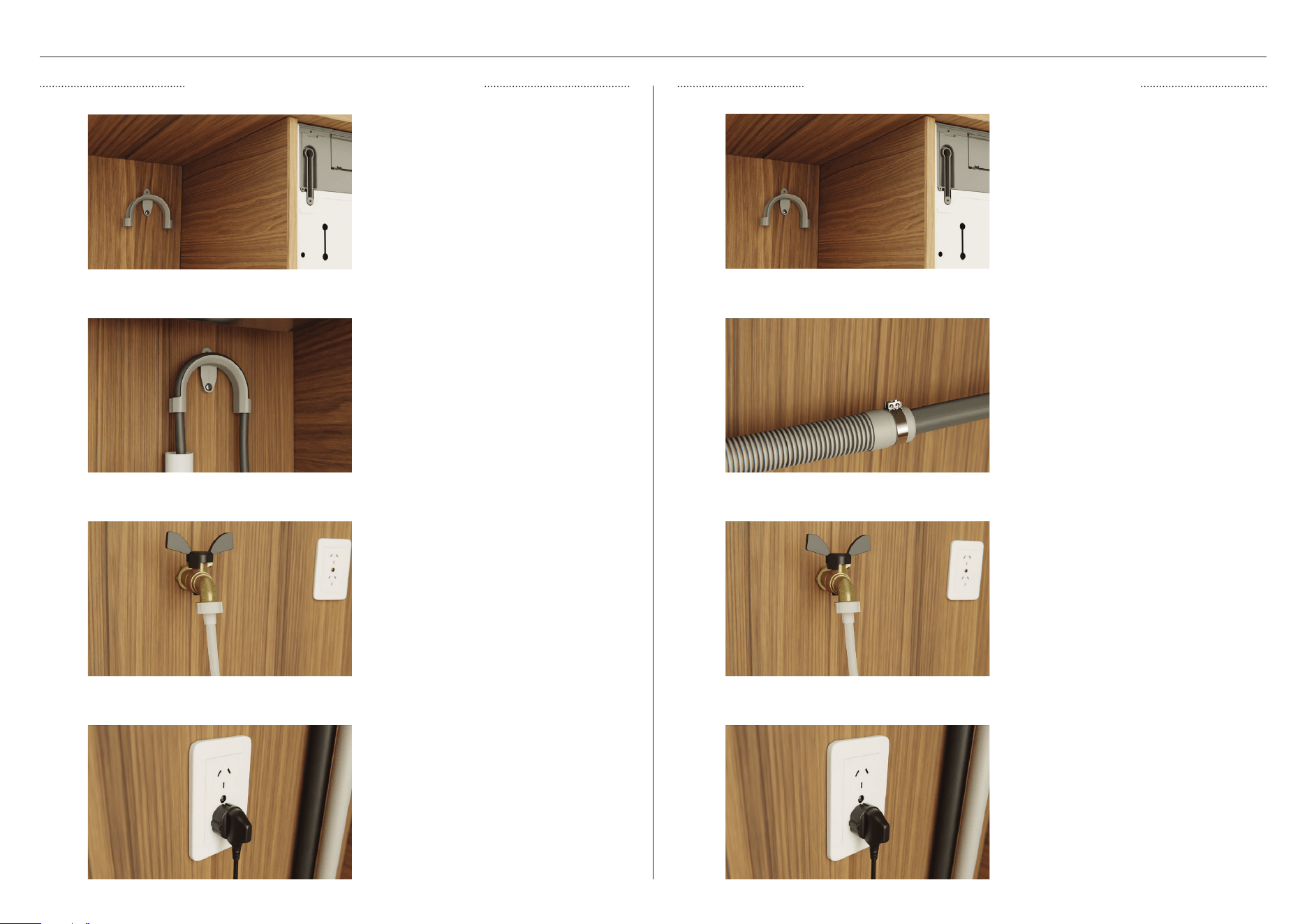
PLUMBING & ELECTRICAL CONNECTION
Install the drain hose support to the
back wall, as close to the underside of
the countertop as possible. Refer to
'Plumbing & electrical considerations' for
minimum install heights.
Install the drain hose support to the
back wall, as close to the underside of
the countertop as possible. Refer to
'Plumbing & electrical considerations' for
minimum install heights.
Pull the hose through the support guide
and rest in standpipe.
Ensure the drain hose does not extend
into water retained in the trap; an air
gap is required to prevent waste water
from siphoning back into the tub.
Plug product in. Plug product in.
Ø38MM STANDPIPE INSTALLATION SINK TRAP/WASTE TEE INSTALLATION
1 1
2 2
3 3
4 4
Pull the hose through the drain hose
support before threading the hose
clamp onto the hose and fitting to
the sink trap. Secure to trap using the
clamp. Ensure hose is routed straight to
the trap.
Unplug or drill out the waste tee to
a minimum of 13mm before securing
joiner to sink trap or waste tee.
Ensure the rubber washer is fitted when
connecting the inlet hose to the tap.
Hand-tighten into place.
Turn a further 180° to secure. A spanner
or pliers may be used, but avoiding
over-tightening.
Do not turn water supply on. The
Dishwasher must be powered on for the
flood protection feature to be enabled.
17
TO BE COMPLETED BY THE INSTALLER
Check all parts are installed correctly and are secure.
Ensure all packaging, tape and rubberbands have been removed.
Ensure all clearance gaps have been maintained.
Ensure Dishwasher is securely fastened to the cabinetry and door opens and closes
freely with no resistance.
Ensure the product is square within the cabinetry and the correct spacers have been
installed to the sides of the product.
Ensure panel is fitted correctly to the Dishwasher
Check the spray arm is in place, mounted correctly and rotates freely.
Ensure all electrical tests have been conducted in accordance with local regulations.
If site is left without power after installation is complete, ensure water supply is
turned off to prevent flooding.
Electrical
Installation
Ensure any knock-outs or plugs in drain connection have been drilled out to a minimum
of 13mm and drain connection has been made.
The drain hose joiner must not support the weight of excess hose material. Keepdrain
hose as fully extended as possible to prevent sagging. Any excess length of drain hose
should be kept on the dishwasher side of the drain hose support.
Ensure inlet hose has supplied rubber washer fitted, and that it is tightened.
If connecting the drain hose to the sink trap, ensure the highloop is a minimum 150mm
higher than the drain hose joiner.
Water softener models: adjust the water softener setting from the default setting to suit
the water hardness of the area. Refer to your user guide.
Ensure water supply is turned off until power is connected and turned on. The
Dishwasher must be powered on for the flood protection feature to be enabled.
Plumbing
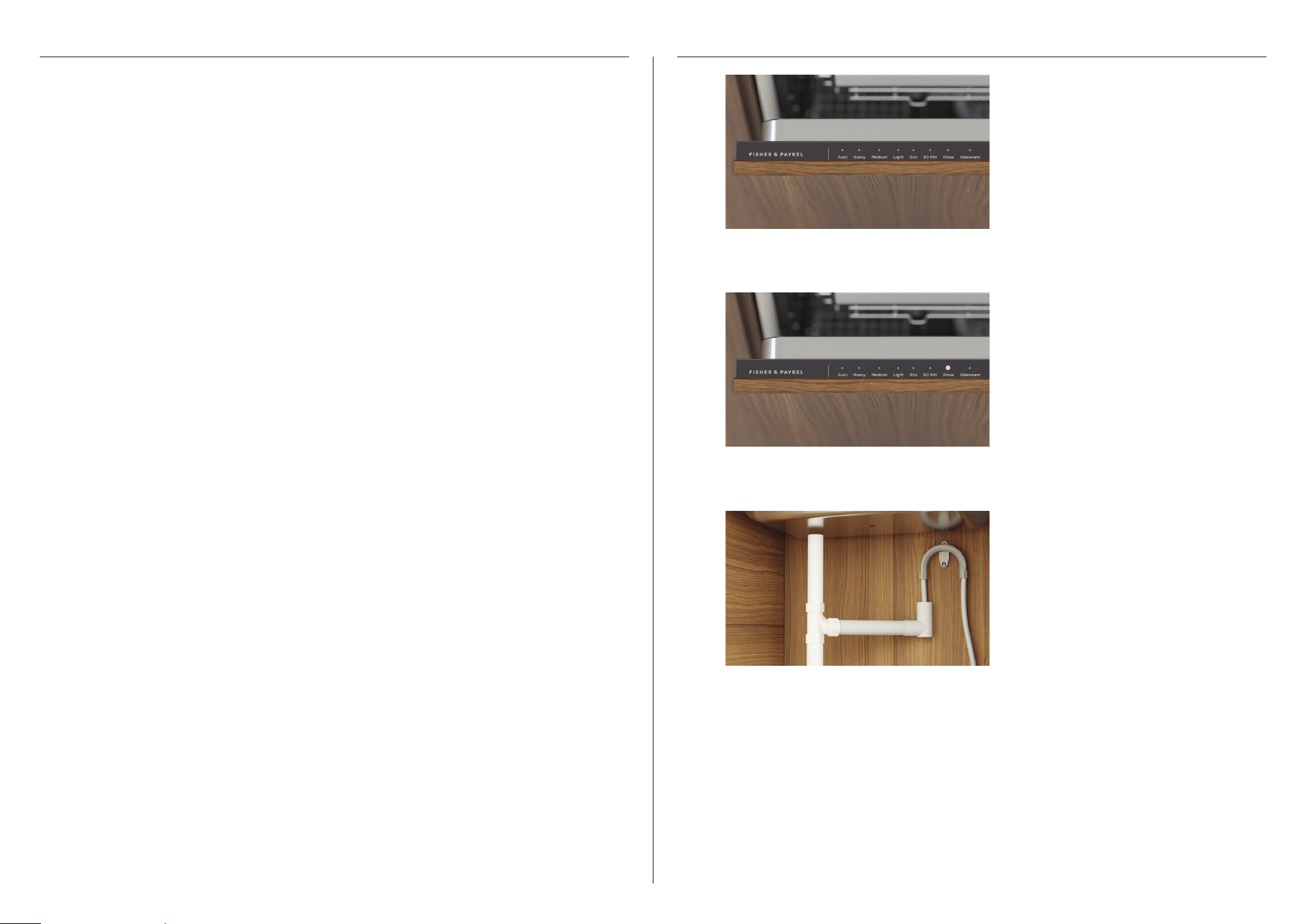
INSTALLER CHECKLIST TEST OPERATION
1
2
3
Turn power and water supply on and
open the dishwasher.
Select
RINSE.
After the
RINSE cycle has finished,
ensure the dishwasher has run and
drainedcorrectly.


592763H 09.24
FISHERPAYKEL.COM
© Fisher & Paykel Appliances 2024. All rights reserved.
The models shown in this guide may not be available in all markets
and are subject to change at any time.
The product specifications in this guide apply to the specific products and
models described at the date of issue. Under our policy of continuous product
improvement, these specifications may change at any time.
For current details about model and specification availability in your country,
please go to our website or contact your local Fisher&Paykel dealer.