
TIG/MMA AC/DC PULSE INVERTER WELDER
200A 230V
MODEL NO: TIGACDC200
Thank you for purchasing a Sealey product. Manufactured to a high standard, this product will, if used according to these
instructions, and properly maintained, give you years of trouble free performance.
IMPORTANT: PLEASE READ THESE INSTRUCTIONS CAREFULLY. NOTE THE SAFE OPERATIONAL REQUIREMENTS, WARNINGS & CAUTIONS. USE
THE PRODUCT CORRECTLY AND WITH CARE FOR THE PURPOSE FOR WHICH IT IS INTENDED. FAILURE TO DO SO MAY CAUSE DAMAGE AND/OR
PERSONAL INJURY AND WILL INVALIDATE THE WARRANTY. KEEP THESE INSTRUCTIONS SAFE FOR FUTURE USE.
1. SAFETY
1.1. ELECTRICAL SAFETY
WARNING! It is the user’s responsibility to check the following:
9 Check all electrical equipment and appliances to ensure that they are safe before using. Inspect power supply leads, plugs and all
electrical connections for wear and damage. Sealey recommend that an RCD (Residual Current Device) is used with all electrical
products.
9 Electrical safety information. It is important that the following information is read and understood:
9 Ensure that the insulation on all cables and on the appliance is safe before connecting it to the power supply.
9 Regularly inspect power supply cables and plugs for wear or damage and check all connections to ensure that they are secure.
Important: Ensure that the voltage rating on the appliance suits the power supply to be used and that the plug is tted with the
9 correct fuse.
8 DO NOT pull or carry the appliance by the power cable.
8 DO NOT pull the plug from the socket by the cable.
8 DO NOT use worn or damaged cables, plugs or connectors. Ensure that any faulty item is repaired or is replaced immediately by a
qualied electrician.
If the cable or plug is damaged during use, switch o the electricity supply and remove from use.
Ensurethatrepairsarecarriedoutbyaqualiedelectrician.
The Electricity at Work Act 1989 requires that all portable electrical appliances, if used on business premises, are tested by a qualified
electrician, using a Portable Appliance Tester (PAT), at least once a year.
1.2. The Health & Safety at Work Act 1974 makes owners of electrical appliances responsible for the safe condition of those appliances
and the safety of the appliance operators. If in any doubt about electrical safety, contact a qualified electrician.
1.3. To achieve maximum output these models will require a 32Amp fused supply. We recommend you discuss the installation of an
industrial round pin plug and socket with your electrician.
1.4. When a cable extension reel is used it should be fully unwound before connection. A cable reel with an RCD fitted is recommended
since any product which is plugged into the cable reel will be protected. The cross-section of the cable on the cable reel must be suitable
for the unit and never lower than the cross-section of the mains cable supplied with the unit.
1.5. GENERAL SAFETY
▲ DANGER! Unplug the welder from the mains power supply before performing maintenance or service.
WARNING! DO NOT place the welding power source on a tilted plane as this may lead to the unit toppling over.
9 Welding power sources are not suitable for use in rain or snow.
9 The output is rated at an ambient temperature of 20°C and the welding time may be reduced at higher temperatures.
9 Risk of electric shock: Electric shock from welding electrode can kill. DO NOT weld in the rain or snow. Wear dry insulating gloves. DO
NOT touch electrode with bare hands. DO NOT wear wet or damaged gloves. Protect yourself from electric shock by insulating yourself
from workpiece. DO NOT open the equipment enclosure.
9 Risk induced by welding fumes: Breathing welding fumes can be hazardous to your health. Keep your head out of the fumes. Use
equipment in an open area. Use ventilating fan to remove fumes.
9 Risk induced by welding sparks: Welding sparks can cause explosion or fire. Keep flammables away from welding. DO NOT weld near
flammables. Welding sparks can cause fires. Have a fire extinguisher nearby and have a watch person ready to use it. DO NOT weld on
drums or any closed containers.
9 Risk induced by the arc: Arc rays can burn eyes and injure skin. Wear hat and safety glasses. Use ear protection and button shirt collar.
Use welding helmet with correct shade of filter. Wear complete body protection.
TIGACDC200 Issue 1 01/10/2024
Original Language Version
© Jack Sealey Limited
Refer to
instructions
Wear protective
gloves
Wear a
welding
mask
Warning!
Electricity
Shock hazard
Warning!
Keep away from
rain
Arc rays can
burn eyes and
injure skin
Electric shock
from welding
electrodes can
kill
Breathing
welding fumes
can be
hazardous to
your health
Electromagnetic
fields can cause
pacemaker
malfunction
Welding sparks
can cause
explosions or fire
NOTE:
Diagrams of internal components are for
reference only. There may be detail differences
in the components of your welder but these will
not affect its operation.

9 Risk induced by electromagnetic fields: Welding current produces electromagnetic field. DO NOT use with medical implants. Never
coil welding cables around your body. Route the welding cables together.
9 Keep the welder and cables in good condition. Take immediate action to repair or replace damaged parts.
9 Use genuine parts and accessories only. Unapproved parts may be dangerous and will invalidate the warranty.
9 Use an air hose to regularly blow out any dirt from the liner and keep the welder clean for best and safest performance.
9 Check and spray the gas cup and contact tip regularly with anti-spatter spray which is available from your Sealey stockist.
9 Locate the welder in a suitable work area. Ensure that the area has adequate ventilation as welding fumes are harmful.
9 Keep work area clean, tidy and free from unrelated materials. Also ensure that the work area has adequate lighting and that a fire
extinguisher is at hand.
WARNING! Use welding head shield to protect eyes and avoid exposing skin to ultraviolet rays given off by electric arc. Wear safety
welding gauntlets.
9 Remove ill fitting clothing, remove ties, watches, rings and other loose jewellery and contain long hair.
9 Ensure that the workpiece is correctly secured before operating the welder.
9 Avoid unintentional contact with workpiece. Accidental or uncontrolled use of the torch may be dangerous and will wear the nozzle.
9 Keep unauthorised persons away from the work area. Any persons working within the area must wear protective head shield and
gloves.
9 Operators must receive adequate training before using the welder.
9 Stand correctly, keeping a good footing and balance, and ensure that the floor is not slippery. Wear non-slip shoes.
9 Turn voltage switch to OFF when not in use.
8 DO NOT operate the welder if it or its cables are damaged and DO NOT attempt to fit any unapproved torch or other parts to the welder
unit.
8 DO NOT get welder wet or use in damp or wet locations or areas where there is condensation.
▲ DANGER! DO NOT weld near inflammable materials, solids, liquids, or gases, and DO NOT weld containers or pipes which
have held flammable materials or gases, liquids or solids. Avoid operating on materials cleaned with chlorinated solvents or
near such solvents. DO NOT use power source for pipe thawing.
8 DO NOT stand welder on a metal workbench, car bodywork or similar object.
8 DO NOT touch any live metal parts of the torch or electrode while the machine is switched on.
8 DO NOT pull the welder by the cable or the torch and DO NOT bend or strain cables. Protect cables from sharp or abrasive items and
DO NOT stand on them. Protect from heat. Long lengths of slack must be gathered and neatly coiled. DO NOT place cables where
they could endanger other people.
8 DO NOT touch the torch or workpiece immediately after welding as they will be very hot. Allow to cool.
8 DO NOT operate welder while under the influence of drugs, alcohol or intoxicating medication, or if tired.
9 When not in use store the welder in a safe, dry, childproof area.
1.6. GAS SAFETY
9 Store gas cylinders in a vertical position only and ensure that the storage area is correctly secured.
8 DO NOT store gas cylinders in areas where temperature exceeds 50°C. DO NOT use direct heat on a cylinder. Always keep gas
cylinders cool.
8 DO NOT attempt to repair or modify any part of a gas cylinder or valve and DO NOT puncture or damage a cylinder.
8 DO NOT obscure or remove any official cylinder labels. Always check the gas identity before use. Avoid getting gas cylinders oily or
greasy.
8 DO NOT lift a cylinder by the cap, guard or valve. Always keep caps and guards in place and close valve when not in use.
WARNING! DO NOT use for pipe thawing.
2. INTRODUCTION
IGBT Inverter technology tted with fan-cooled AC/DC power supply suitable for both TIG and MMA/ARC welding applications up
to 200A. Suitable for welding a variety of metals including aluminium, magnesium, stainless steel, copper, nickel and titanium.
20-stage parameter adjustment program to suit welders’ requirements. Weighing 8.5kg this welder is highly portable allowing
the welder to be taken to the job at hand making it ideal for the mobile technician. Features hot start, anti-stick, forced air
cooling, thermal cut-out protection and quick release switch on the torch for control of gas, saving on consumption. Suitable for
MMA/ARC welding using the lift start method for better weld quality. Supplied with earth clamp, TIG torch and accessories,
electrode holder and foot pedal for when greater control is required.
3. SPECIFICATION
Original Language Version
© Jack Sealey Limited
TIGACDC200 Issue 1 01/10/2024
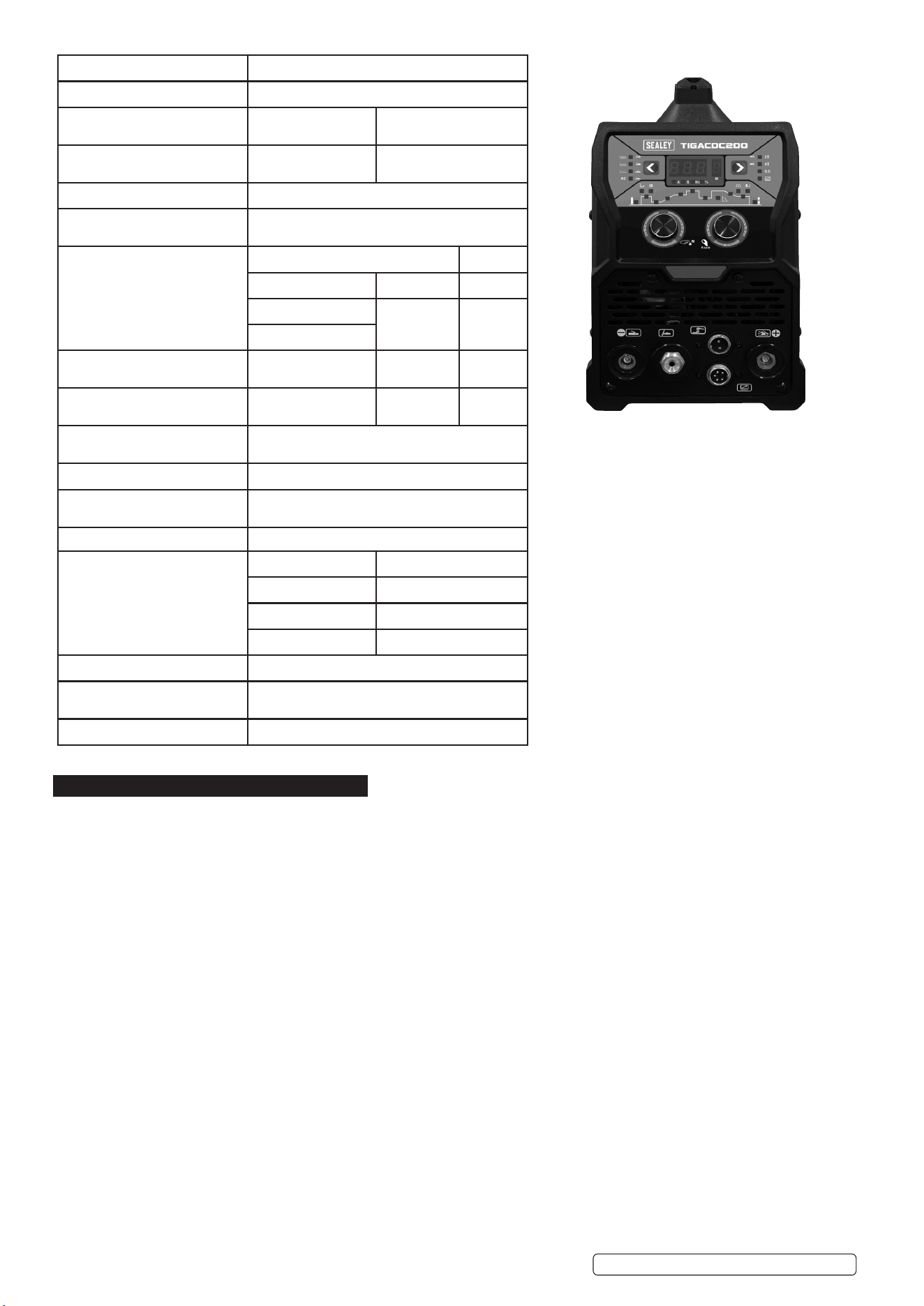
Model no: TIGACDC200
Absorbed Power: 5.4kW
Duty Cycle: AC - 100% @ 110A, 60% @ 141A, 30% @ 200A.
DC - 100% @ 93A, 60% @ 120A, 30% @170A.
Electrode Capacity: Ø1.6-4mm
EMC EN IEC 60974-1:2018+A1:2019
Insulation Class: F
Nett Weight: 8.5kg
Plug Type: Bare Wire
Power Output: 10-200A
Plug Type: Bare Wire
Power Supply Cable Length: 2m
ADDITIONAL INFORMATION
Pollution Degree 3
Protection: IP21S
Static Characteristics Drooping
Supply: 230V/50Hz
ACCESSORIES
Earth Clamp TIGACDC200 -22
Electrode Holder TIGACDC200 -23
Foot Pedal TIGACDC200-24
Tig Torch TIGACDC200-21
4. OPERATION
4.1. DUTY CYCLE AND OVER HEAT / THERMAL PROTECTION
Duty cycle is dened as the proportion of the time that a machine can work continuously within a certain time (10 minutes). The rated
duty cycle means the proportion of the time that a machine can work continuously within 10 minutes when it outputs the rated welding
current. If the welder overheats, the IGBT overheating protection unit inside the appliance will instruct the appliance to cut the
output welding current, and will light the overheat pilot lamp on the front panel. At this time, the machine should be rested for 15
minutes to allow to cool. When restarting the machine, the welding output current or the duty cycle should be reduced.
4.2. MOVEMENT AND PLACEMENT
Please take care of the welder when moving it, and do not carry on its side. It can also be moved by the handle on the top of the
welder. Place the welder well when moving it to the right position. The movement may result in the potential danger or substantive
hazard, so please make sure that the machine is in a safe position before using it.
4.3. POWER SUPPLY INPUT CONNECTION
The TIGACDC200 welding machine power supply connects to 230V. When the power supply voltage is over the safe work voltage,
there are over voltage and under voltage protection inside the welder, the alarm light will come on, at the same time, the current output
will be cut o. If the power supply voltage continually goes beyond the safe work voltage range, it will shorten the welder life-span. The
below measures can be used:
4.3.1. Change the power supply input. Such as, connect the welder with the stable power supply voltage or distribution.
4.3.2. Reduce the machines using the same power supply at the same time;
4.3.3. Set the voltage stabilisation device in the front of power cable input (see control panel 4.7).
4.4. ENVIRONMENT
4.4.1. Height above sea level is below 1000m.
4.4.2. Operation temperature range:-10 to 40.
4.4.3. Relative humidity is below 90 % (200C).
4.4.4. Preferably site the machine some angles above the oor level, the maximum angle does not exceed 150 degrees.
4.4.5. Protect the machine against heavy rain or in hot circumstance against direct sunshine.
4.4.6. The content of dust, acid, corrosive gas in the surrounding air or substance can not exceed normal standard.
4.4.7. Take care that there is sucient ventilation during welding with at least 30cm free distance between the machine and the wall.
Original Language Version
© Jack Sealey Limited
TIGACDC200 Issue 1 01/10/2024
Model TIGACDC200
Supply 230±10%, 50Hz
Rated input current (A) (TIG) 25.2 (MMA) 31.9
Rated input power
(kW)
(TIG) 5.8 (MMA) 7.3
Power factor 0.73
Max no-load
Voltage (V)
56
Adjustment range of
Start current (A)
TIG MMA
AC DC DC
HF 1 to 200 _
1 to 200
Adjustment range of
Welding current (A)
10 to 200 10 to 200 10 to 170
Adjustment range of
Crater arc current (A)
10 to 200 10 to 200 20 to 170
Adjustment range of
Downslope time (S)
0 to10
Pre-gas time (S) 0.1 to 3
Adjustment range of
Post-gas time (S)
1.0 to 10
Clearance eect (%) -40 to 10
Eciency
Duty cycle (25°C.
10 minutes).
AC DC
30% 200A 30% 170A
60% 141A 60% 120A
100% 110A 100% 93A
Protection class IP21S
Dimensions of Machine
(L×W×H) (mm)
400*170*300
Weight (kg) 8.5
4.5. MMA WELDING
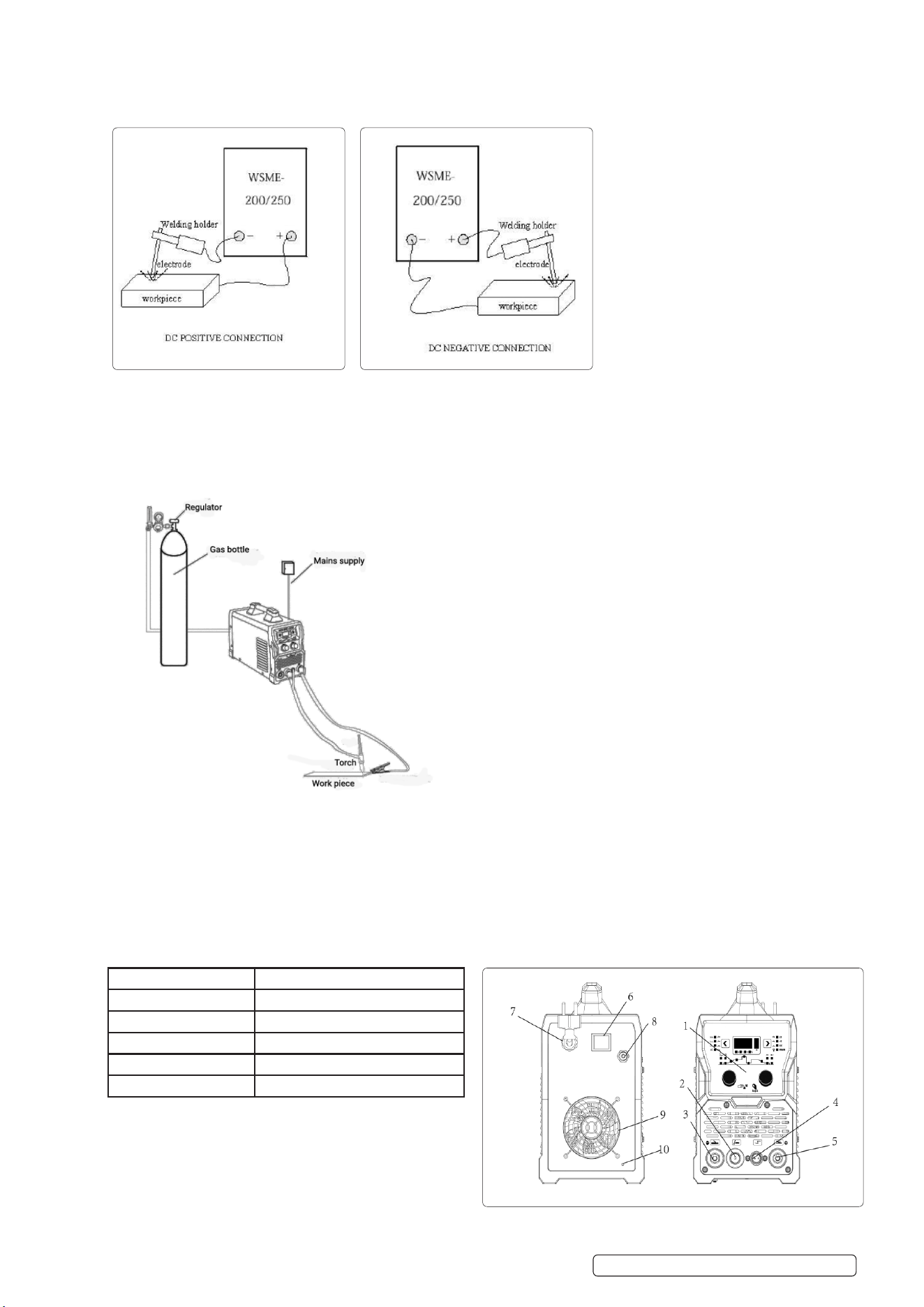
MMA (DC): Choosing the connection of DCEN or DCEP according to the dierent electrode. Please refer to the electrode manual.
4.5.1. Connect the electrode holder and earth clamp correctly see above.
4.5.2. Plug in, turn on the switch, power indicator light is on.
4.5.3. Short press on parameter selection knob, choose the pre-set parameter, or the parameter set you want to save.
4.5.4. Select to MMA function.
4.5.5. Choose dierent welding current according to dierent workpiece thickness and electrode diameter.
4.5.6. Start welding.
4.6. TIG WELDING
4.6.1. Refer to Panel layout, connect TIG torch and earth clamp correctly as above, plug in and connect the shielding gas (make sure
you connect to right voltage).
4.6.2. Turn on the switch, power indicator light is on. Open the argon cylinder valve and adjust the shielding gas ow appropriately. (See
below).
4.6.3. Select dierent TIG function according to dierent workpiece material and thickness (see tables 4.14 to 4.17).
4.6.4. Short press on parameter selection knob, choose the pre-set parameter, or the parameter set you want to save.
4.6.5. Choose 2T or 4T function according to dierent workpiece material and thickness.
4.6.6. Turn the parameter selection knob and parameter adjust knob, set an appropriate parameter.
4.6.7. Start welding.
4.7. STRUCTURE OF MACHINE
1.Operating panel 2.TIG torch connector
3.Negative connector 4.TIG torch switch control interface
5.Positive connector 6.Power switch
7.Power cable 8.Argon connector
9.Fan 10.Earth
11.Foot switch
Original Language Version
© Jack Sealey Limited
TIGACDC200 Issue 1 01/10/2024
TIGACDC200 Issue 1 01/10/2024
Original Language Version
© Jack Sealey Limited
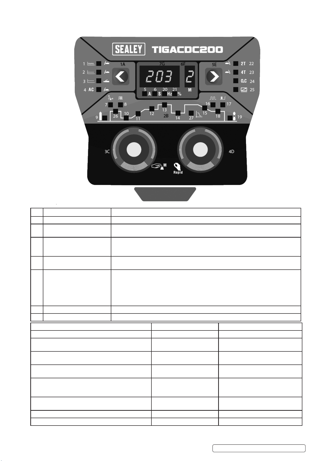
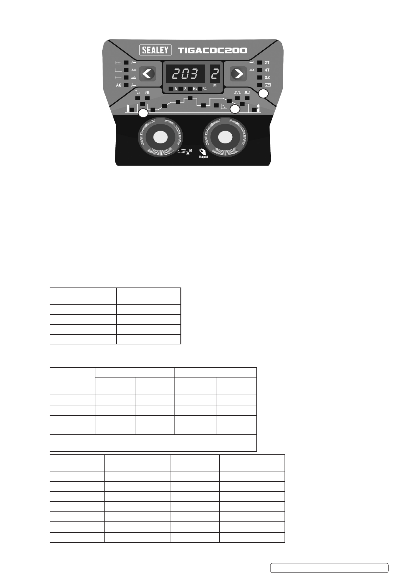
4.8. CONTROL PANEL SETTINGS AND LOCATIONS
NO NAME FUNCTION
1A. Main function selection button. Options: pulse TIG, pulse TIG+AC, DC TIG, DC TIG+AC, MMA.
2B. Pulse TIG indicator light. 1.Indicate pulse function currently under adjustment.
2.Under pulse TIG welding, indicate currently welding condition.
3C. TIG welding parameter
selection knob.
Turn: The knob to choose the pulse parameter that needs to be adjusted.
Short press: retrieve the parameters in storage.
Long press: save current parameter.
4D. Welding parameter adjust knob. Turn the knob to adjust the welding parameter, short press to the knob could change adjust
speed (slow adjust and quick adjust).
5E. 2T/4T Select button. 2T: Press the torch switch, machine starts welding, release the torch switch, machine stops
welding.
4T:Press the torch switch, machine starts to arc. When the torch switch is released, the
current starts to climb up to the normal welding current. When the welding is completed,press
torch switch again, and the welding current begins to drop the arcing current. Release the
torch switch, stop welding.
6F. Parameter sets. The machine could save 6 sets parameter under each function, shown by 1-6.
7. Welding parameter value. Welding current (A), gas pre and post ow time (S), pulse frequency (Hz), duty cycle (%)
1 .Pulse TIG 2. DC TIG 3. MMA
4. AC 5. Current unit (A) 6. Time unit (S)
7. AC clean area width
Regulating range -40% to 40%
8. AC frequency Regulationg
range: 20Hz to 200Hz
9. Gas pre time. Regulation range: 0
to 3s
10. Arc strike current WSME-180 regulation range:10-180A
WSME-200 regulation range:10-200A
11. Current slow increase time
Regulation range: 0-10s
12. DC TIG constant current,
Regulation range:10-200A.
13. Pulse TIG peak current
Regulation range: 10-200A
14.Current decrease time
Regulation range: 0-10s
15.Pulse TIG pulse frequency,
Regulation range:0.1Hz to 999Hz
16. Pulse TIG duty cycle (pulse width)
Regulation range: 10% to 90%
17. Arc ending current WSME-
180 regulation range: 10-180A.
Regulation range: 10-200A.
18. Post ow time
Regulation range: 1.0 to 10s
19. Frequency unit (Hz) 20. Percentage (duty cycle)
unit (%)
21. Percentage (duty cycle) unit (%)
22. 2T function 23. 4T function 24. Protection indicate
25. Foot switch ON/OFF 26. Hot arc ignition 27. Arc Force
4.9. FOOT PEDAL (TIG)
4.9.1. Arc force MMA
4.9.2. THE POSITIONS OF THE NEW FUNCTIONS ON THE PANEL ARE POSITION 1. 2. 3. SHOWN ABOVE.
4.10. 3: TIG remote control function indicator light
4.10.1. ON: Foot pedal connector inserted, the indicator light is on, remote control function is turned on.
4.10.2. OFF: Foot pedal connector removed, this indicator light will be o, remote control function is turned o.
● In the TIG position, after the remote control function is turned on, the functions of striking current, slow raising, slow descending,
ending current cannot be used, all will be controlled by foot petal potentiometer.
● In the state of pulsed TIG, when using remote control function, please reasonably set the valley current in advance. The foot pedal
potentiometer control of the peak current in the remote control state, the valley current is always the current value set on the panel.
● After the remote control function is turned on, the minimum current of TIG+AC function and pulsed TIG+AC function is 20A (when
remote control is o state the minimum current is 10A).
● In the state of MM, there is no remote control function, insert or pull o the foot petal connector, the indicator light will be o, other
functions are not aected.
4.11. 1: MMA hot start function, adjustable range: 0-50A.
4.12. 2: MMA ARC force function, adjustable range: 0-50A.
4.13. TIG PARAMETERS
4.14. GAS NOZZLE AND SHIELD GAS FLOW RATE
TIGACDC200 Issue 1 01/10/2024
Original Language Version
© Jack Sealey Limited
1
2
3
Gas nozzle diameter/
mm
Electrode diameter/mm
6.4 0.5
8 1.0
9.5 1.6 or 2.4
11.1 3.2
Welding
current
Range/A
DC positive connection AC
Gas nozzle
Diameter/mm
Ga s o w
rate/L* min⁻¹
Gas nozzle
Diameter/mm
Gas ow
Rate/L*min⁻¹
10 to 100 4 to 9.5 4 to 5 8 to 9.5 6 to 8
101 to 150 4 to 9.5 4 to 7 9.5 to 11 7 to 10
151 to 200 6 to 13 6 to 8 11 to 13 7 to 10
201 to 300 8 to 13 8 to 9 13 to 16 8 to 15
Notice: the above parameters originate from (Welding Dictionary) P149, Volume
1 of Edition 2.
Tungsten electrode
diameter /mm
Sharpened of the
electrode diameter/mm
Angle of cone (°) Background current/A
1.0 0.125 12 2 to 15
1.0 0.25 20 5 to 30
1.6 0.5 25 8 to 50
1.6 0.8 30 10 to 70
2.4 0.8 35 12 to 90
2.4 1.1 45 15 to 150
3.2 1.1 60 20 to 200

4.15. TIG (STAINLESS STEEL SINGLE RUN WELDING).
4.16. PARAMETERS OF PIPING BACK SEALING WELDING FOR MILD STEEL (DCEP)
4.17. PARAMETERS OF AC TIG (MMA) FOR ALUMINIUM AND ITS ALLOY
Workpiece
thickness /mm
Joint form Tungsten electrode
diameter/mm
Welding wire
diameter/m
Argon gas
ow rate/
L* min⁻¹
Welding
current
(DCEP)
Welding
speed/cm *
min
0.8 Butt joint 1.0 1.6 5 20 to 50 66
1.0 Butt joint 1.6 1.6 5 50 to 80 56
1.5 Butt joint 1.6 1.6 7 65 to 105 30
1.5 Corner joint 1.6 1.6 7 75 to 125 25
2.4 Butt joint 1.6 2.4 7 85 to 125 30
2.4 Corner joint 1.6 2.4 7 95 to 135 25
3.2 Butt joint 1.6 2.4 7 100 to 135 30
3.2 Corner joint 1.6 2.4 7 115 to 145 25
4.8 Butt joint 2.4 3.2 8 150 to 225 25
4.8 Corner joint 3.2 3.2 9 175 to 250 20
Note: the above parameters originate from (Welding Dictionary) P150, Volume 1 of Edition 2.
TIGACDC200 Issue 1 01/10/2024
Original Language Version
© Jack Sealey Limited
Piping
diameter Φ/
mm
Tungsten
electrode
diameter/mm
Gas nozzle
Diameter/mm
Welding wire
diameter/mm
Welding
current/A
Arc
voltage/V
Argon ow
rate/ L* min⁻¹
Welding
rate/ cm*
min⁻¹
38 2.0 8 2 75 to 90 11 to 13 6 to 8 4 to 5
42 2.0 8 2 75 to 95 11 to 13 6 to 8 4 to 5
60 2.0 8 2 75 to 100 11 to 13 7 to 9 4 to 5
76 2.5 8 to 10 2.5 80 to 105 14 to 16 8 to 101 4 to 5
108 2.5 8 to 10 2.5 90 to 110 14 to 16 9 to 11 5 to 6
133 2.5 8 to 10 2.5 90 to 115 14 to 16 10 to 12 5 to 6
159 2.5 8 to10 2.5 95 to 120 14 to 16 11 to 13 5 to 6
219 2.5 8 to10 2.5 100 to 120 14 to 16 12 to 14 5 to 6
273 2.5 8 to 10 2.5 110 to 125 14 to 16 12 to 14 5 to 6
325 2.5 8 to 10 2.5 120 to 140 14 to 16 12 to 14 5 to 6
Note: The above parameters originate from (Welding Dictionary) P167, Volume 1 of Edition 2.
Sheet thickness/mm Welding wire diameter
/mm
Tungsten electrode
Diameter/mm
Pre-heat
Temperature/⁰C
Welding
current/A
Argon ow
RateL*min⁻¹
Gas nozzle
diameter
/mm
Type
1 1.6 2 _ 45 to 60 7 to 9 8 Flange
welding
1.5 2 _ 50 to 80 7 to 9 8 Flange
or butt
welding by
one side
2 2 to 2.5 2 to 3 _ 90 to 120 8 to 12 812 Butt
welding
3 2 to 3 3 _ 150 to 180 8 to 12 8 to 12
V-groove
butt
welding
4 3 4 _ 180 to 200 10 to 15 8 to 12
5 3 to 4 4 _ 180 to 240 10 to 15 10 to 12
6 4 5 _ 240 to 280 16 to 20 14 to 16
8 4 to 5 5 100 260 to 320 16 to 20 14 to 16
10 4 to 5 5 100 to 150 280 to 340 16 to 20 14 to 16
12 4 to 5 4 to 5 150 to 200 300 to 360 18 to 22 16 to 20
14 5 to 6 5 to 6 180 to 200 340 to 380 20 to 24 16 to 20
16 5 to 6 6 200 to 220 340 to 380 20 to 24 16 to 20
18 5 to 6 6 200 to 240 360 to 400 25 to 30 16 to 20
20 5 to 6 6 200 to 260 360 to 400 25 to 30 20 to 22
16~20 5 to 6 6 200 to 260 300 to 380 25 to 30 16 to 20 X-groove
butt
welding
22~25 5 to 6 6 to 7 200 to 260 360 to 400 30 to 35 20 to 22
Note: The above parameters originate from (Welding Dictionary) P538, Volume 2 of Edition 2.
5. MAINTENANCE
▲ DANGER! Unplug the inverter from the mains power supply before connecting or disconnecting cables or performing
maintenance or service. Direct contact with the inverter circuit is dangerous.
5.1. To avoid a build up of dust inside the machine which may block or restrict the ventilation system, periodically remove the covers and
remove the dust with a low pressure air jet or vacuum cleaner. Replace covers immediately. Under no circumstances should the
machine be operated with the covers removed.
5.2. TORCH. Avoid resting the torch and its associated cable on any hot surfaces. If the insulation is damaged in any way the torch
must not be used.
5.3. Periodically check the condition of the gas tubing and the connections.
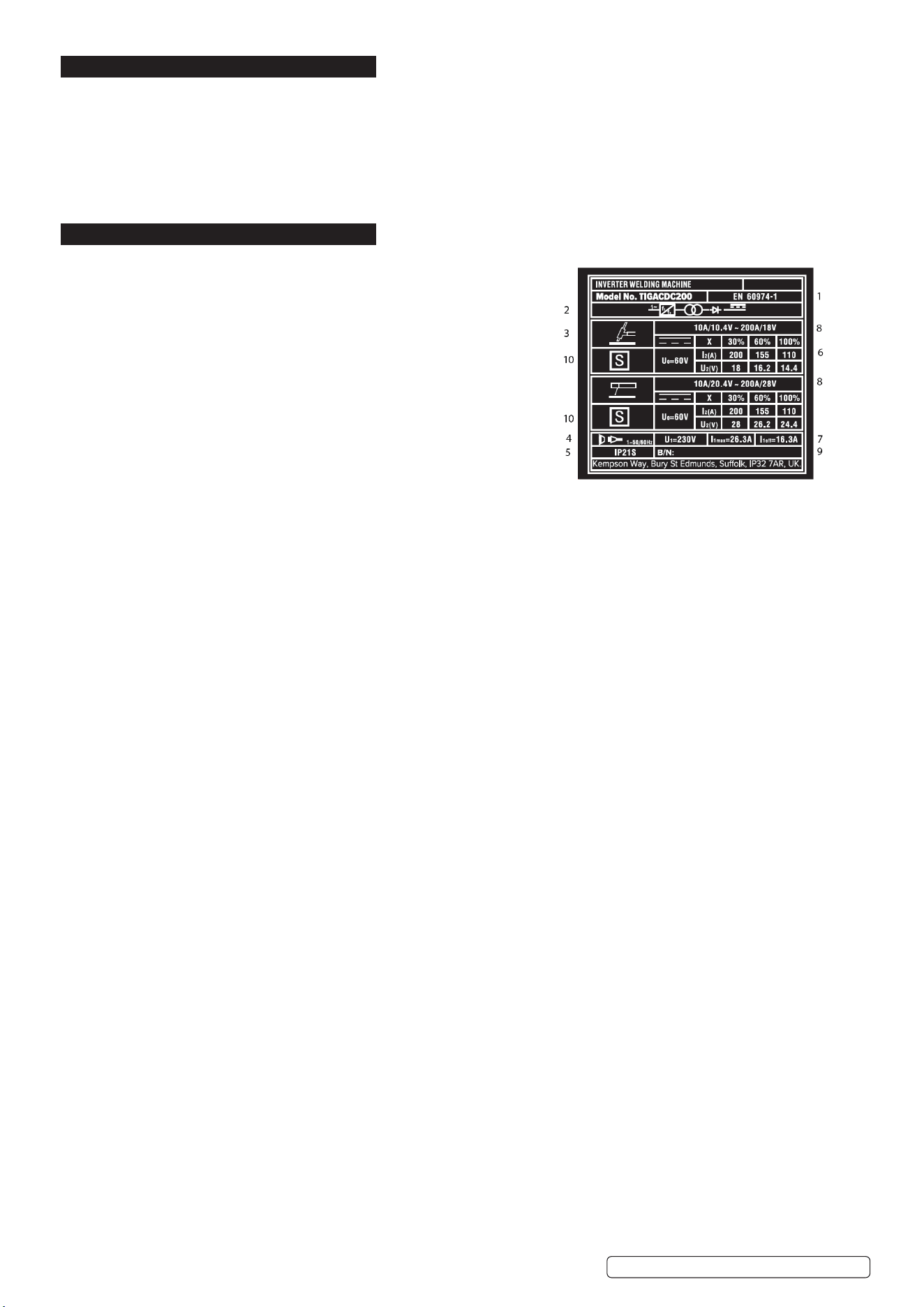
6. RATINGS PLATE SYMBOLS
6.1. On the rear of the inverter is the ratings plate, giving the following data:
1 -The BS/EU standard relating to the safety and construction of
arc welding and associated equipment.
2 -Inverter-transformer-rectifier symbols.
3 -Symbol indicates welding with a continuous flow of welding wire.
4 -Symbol for Single-phase AC supply.
5 -Rating of internal protection provided by casing.
6 - Output:
U0: Maximum open-circuit voltage.
I2, U2: Current and corresponding voltage.
X: Welding ratio based on a 10 minute cycle.
20% indicates 2 minutes welding and 8 minutes rest,
100% would indicate continuous welding.
7 -Mains Supply
U1: Rated supply voltage and frequency.
I1max: Maximum current. I1eff: Maximum effective current.
8 -A/V - A/V:Welding current adjustment range and corresponding voltages.
9 - Serial Number. Specifically identifies each welder.
10-Symbol for welding power sources which are suitable for supplying power to welding operations carried out in an environment with
increased risk of electric shock (if applicable).
TIGACDC200 Issue 1 01/10/2024
Original Language Version
© Jack Sealey Limited

7. TROUBLESHOOTING
Fault Diagnosis Solution
When turning on the fan works, but the power pilot lamp
is not on.
The power light is damaged or poor
connection.
Make good the connection, or replace
the wiring
The front panel PCB damaged Repair or change the PCB.
When switching on the power lamp is on, but fan
doesn’t work
There is something jammed in the fan Remove the oending artical.
Poor connection to the fan Ret connection.
The fan motor damaged Change power switch.
Turn on the power the power lamp is not on, and fan
doesn’t work
No power supplied. Ensure that there is power supplied to
the unit.
Power switch damaged Change fan motor.
The number on the display is partially lit. The front panel PCB damaged The front panel PCB needs replacing.
No no-load voltage output
(MMA).
The machine is damaged. Check the mains circuit.
Arc can’t be ignited (TIG).
There is spark on the HF
igniting board
The welding cable is not connected to
the output of the welder.
Connect the welding cable to the
welder’s output.
The welding cable damaged Repair or change it.
The earth cable connected but has a
bad earth.
Check the earth cable.
The welding cable is too long. Use an appropriate welding cable.
There is oil or dust on the workpiece. Check and remove it.
The distance between tungsten
electrode
And workpiece is too long.
Reduce the distance (about 3mm).
There is no spark on
the HF igniting board.
The y back transformer on the main
board is damaged
Change the y back transformer
The distance between the discharger is
too short.
Adjust this distance (about 0.7mm).
Malfunction of the welding gun switch. Check the welding gun switch, control
cable and aero socket.
No gas ow (TIG)
Gas cylinder is closed or
gas pressure is low
Open or change the gas cylinder
Something in the valve Remove it.
Electromagnetic valve is
damaged
Replace it.
Gas constantly owing
Something in the valve Remove it.
Electromagnetic valve is
damaged
Replace valve.
The welding current can not
be adjusted
The front panel PCB
damaged.
Repair or change the PCB
No AC output while
selecting “AC”
The power PCB is faulty. Repair or change it.
The AC drive PCB
damaged.
Change PCB.
The AC IGBT module
damaged.
Change the module.
The penetration of molten
pool is not enough.
The welding current is
adjusted too low.
Increase the welding current.
The arc is too long in the
welding process.
Use 2T operation.
The alarm lamp on the front
Panel is on.
Over heat protection. Working for too long a period. Reduce operational time.
Over-voltage protection. Power supply uctuates. Use a stable power supply.
Low-voltage protection.
Power supply uctuates. Use a stable power supply.
Too many machines using power supply
at the same time
Reduce the machines using power
supply at the same time.
Over-current protection Power surge in power supply. Check power supply and drive unit.
TIGACDC200 Issue 1 01/10/2024
Original Language Version
© Jack Sealey Limited

Sealey Group, Kempson Way, Suffolk Business Park, Bury St Edmunds, Suffolk. IP32 7AR
01284 757500 sales@sealey.co.uk www.sealey.co.uk
ENVIRONMENT PROTECTION
Recycle unwanted materials instead of disposing of them as waste. All tools, accessories and packaging should be sorted,
taken to a recycling centre and disposed of in a manner which is compatible with the environment. When the product
becomes completely unserviceable and requires disposal, drain any fluids (if applicable) into approved containers and
dispose of the product and fluids according to local regulations.
WEEE REGULATIONS
Dispose of this product at the end of its working life in compliance with the EU Directive on Waste Electrical and Electronic Equipment
(WEEE). When the product is no longer required, it must be disposed of in an environmentally protective way. Contact your local solid
waste authority for recycling information.
Original Language Version
© Jack Sealey Limited
REGISTER YOUR
PURCHASE HERE
TIGACDC200 Issue 1 01/10/2024
Note: It is our policy to continually improve products and as such we reserve the right to alter data, specifications and component parts without prior
notice.
Important: No Liability is accepted for incorrect use of this product.
Warranty: Guarantee is 12 months from purchase date, proof of which is required for any claim.