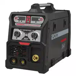
200A MIG, TIG & MMA INVERTER WELDER
MODEL NO: INVMIG200.V3
Thank you for purchasing a Sealey product. Manufactured to a high standard, this product will, if used according to these instructions,
and properly maintained, give you years of trouble free performance.
IMPORTANT: PLEASE READ THESE INSTRUCTIONS CAREFULLY. NOTE THE SAFE OPERATIONAL REQUIREMENTS, WARNINGS & CAUTIONS. USE
THE PRODUCT CORRECTLY AND WITH CARE FOR THE PURPOSE FOR WHICH IT IS INTENDED. FAILURE TO DO SO MAY CAUSE DAMAGE AND/OR
PERSONAL INJURY AND WILL INVALIDATE THE WARRANTY.
1. SAFETY
1.1. ELECTRICAL SAFETY
WARNING! It is the owner’s responsibility to read, understand and comply with the following:
You must check all electrical equipment and appliances to ensure that they are safe before use. You must inspect power supply leads,
plugs and all electrical connections for wear and damage. You must ensure the risk of electric shock is minimised by the installation of
appropriate safety devices. An RCCB (Residual Current Circuit Breaker) should be incorporated in the main distribution board. We also
recommend that an RCD (Residual Current Device) is used with all electrical products. It is particularly important to use an RCD with
portable products that are plugged into an electrical supply not protected by an RCCB. If in doubt consult a qualified electrician.
You must also read and understand the following instructions concerning electrical safety.
1.1.1. The Electricity At Work Act 1989 requires all portable electrical appliances, if used on business premises, to be tested by a qualied
electrician, using a Portable Appliance Tester (PAT), at least once a year.
1.1.2. The Health & Safety at Work Act 1974 makes owners of electrical appliances responsible for the safe condition of the appliance
and the safety of the appliance operator. If in any doubt about electrical safety, contact a qualified electrician.
Ensure the insulation on all cables and the product itself is safe before connecting to the mains power supply.
See 1.1.1. & 1.1.2. above and use a Portable Appliance Tester (PAT).
Ensure that cables are always protected against short circuit and overload.
Regularly inspect power supply, leads, plugs for wear and damage and all electrical connections
to ensure that none is loose.
Important: Ensure the voltage marked on the product is the same as the electrical power supply
to be used and check that supply is correctly fused, see fuse rating at right.
8 DO NOT pull or carry the powered appliance by its power supply lead.
8 DO NOT pull power plugs from sockets by the power cable.
8 DO NOT use worn or damaged leads, plugs or connections. Immediately replace or have
repaired by a qualified electrician.
This product comes without a plug. You must contact a qualified electrician to ensure an
adequate supply is available.
If fitting such a plug -
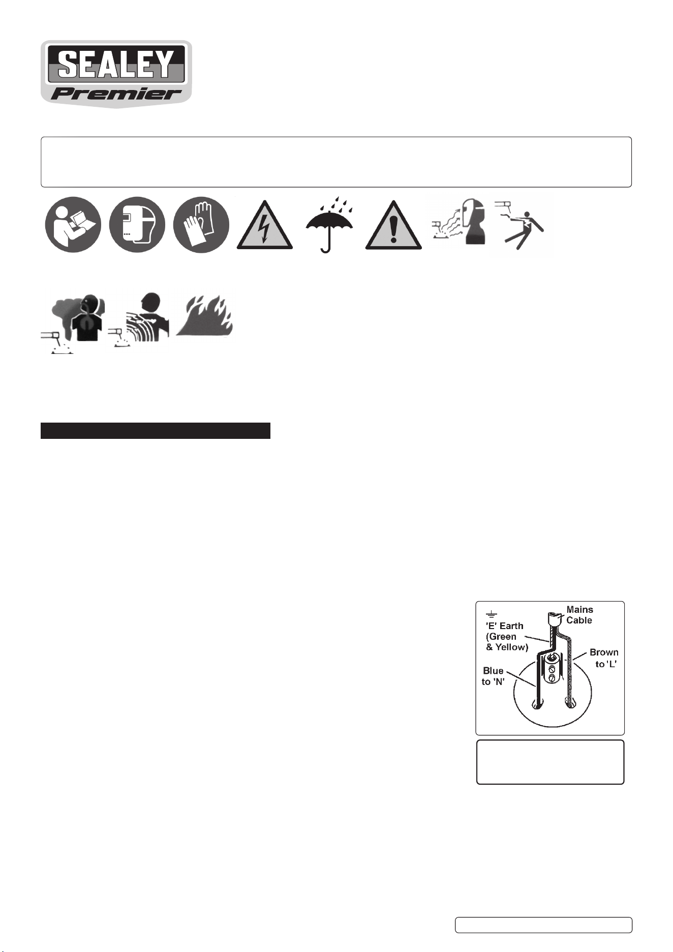
Ensure that the unit is correctly wired and earthed, as follows:
a) Connect the GREEN/YELLOW earth wire to the earth terminal ‘E’.
b) Connect the BROWN live wire to live terminal ‘L’.
c) Connect the BLUE neutral wire to the neutral terminal ‘N’.
d) After wiring, check there are no bare wires, that all wires have been correctly connected, that the cable outer
insulation is clamped by the cable grip and that the grip is tight.
1.1.3. Cable extension reels. When a cable extension reel is used it should be fully unwound before connection. A cable reel with an RCD
fitted is recommended since any product which is plugged into the cable reel will be protected. The section of the cores of the cable is
important. 2.5mm² section is a minimum, but to be absolutely sure that the capacity of the cable reel is suitable for this product and
for others that may be used in the other output sockets, we recommend the use of 2.5mm² section cable.
1.1.4. IMPORTANT! To achieve maximum output INVMIG200.V3 will require a 32A fused supply. We recommend you discuss the
installation of an industrial round pin plug and socket with a competent electrician.
THIS PRODUCT REQUIRES A
MINIMUM 16 AMP
SUPPLY
Refer to
instruction
manual
Wear a
welding
mask
Wear protective
gloves
Warning!
Electricity
shock hazard
Warning!
Keep away
from rain
Caution
required
Arc rays can
burn eyes and
injure skin
Breathing
welding fumes
can be
hazardous to
your health
Electric shock
from welding
electrodes can
kill
Electromagnetic
fields can cause
pacemaker
malfunction
Welding sparks
can cause
explosions
or fire
Original Language Version
© Jack Sealey Limited
INVMIG200.V3 Issue: 2 (1) 18/01/23

WARNING! Be very cautious if using a generator to power the welder. The generator must be self-regulating and stable with regard
to voltage, wave form and frequency. The output must be greater than the power consumption of the welder. If any of these requirements
is not met the electronics within the welder may be affected.
NOTE: The use of an unregulated generator may be dangerous and will invalidate the warranty on the welder.
WARNING! The welder may produce voltage surges in the mains supply which can damage other sensitive equipment
(e.g. computers). To prevent this happening, it is recommended that the welder is connected to a power supply that does not
feed any sensitive equipment.
1.2. GENERAL SAFETY
▲ DANGER! Unplug the welder from the mains power supply before performing maintenance or service.
9 Keep the welder and cables in good working order and condition. Take immediate action to repair or replace damaged parts.
9 Use genuine parts and accessories only. Unapproved parts may be dangerous and will invalidate the warranty.
9 Use an air hose to regularly blow out any dirt from the liner and keep the welder clean for best and safest performance.
9 Check and spray the gas cup and contact tip regularly with anti-spatter spray, available from your Sealey stockist.
9 Locate welder in a suitable work area. Ensure that the area has adequate ventilation as welding fumes are harmful.
9 Keep work area clean, tidy and free from unrelated materials. Also ensure the working area has adequate lighting and that a fire
extinguisher is at hand.
WARNING! Use welding head shield to protect eyes and avoid exposing skin to ultraviolet rays given off by electric arc. Wear
safety welding gauntlets.
9 Remove ill fitting clothing, remove ties, watches, rings and other loose jewellery and contain long hair.
9 Ensure the workpiece is correctly secured before welding.
9 Avoid unintentional contact with the workpiece. Accidental or uncontrolled use of the torch may be dangerous and will wear the nozzle.
9 Keep unauthorised persons away from the work area. Any persons working within the area must wear a protective head shield and gloves.
9 Operators must receive adequate training before using the welder.
9 Stand correctly keeping a good footing and balance, ensure the floor is not slippery and wear non-slip shoes.
8 DO NOT operate the welder if it or the cables are damaged and DO NOT attempt to fit any unapproved torches or other
components to the welder.
8 DO NOT get welder wet or use in damp or wet locations or areas where there is condensation.
▲ DANGER! DO NOT weld near flammable solids, liquids or gases and DO NOT weld containers or pipes which have held
flammable materials. Avoid welding materials which have been cleaned with chlorinated solvents or welding near such solvents.
8 DO NOT stand welder on a metal workbench, car bodywork or similar.
8 DO NOT touch any live metal parts of the torch or electrode while the machine is switched on.
8 DO NOT pull the welder by the cable, or the torch. Protect cables from sharp or abrasive items. DO NOT bend, strain or stand on cables
or leads.
9 Protect from heat. Long lengths of slack must be gathered and neatly coiled. DO NOT place cables where they endanger others.
8 DO NOT touch the torch or workpiece immediately after welding as they will be very hot. Allow to cool.
8 DO NOT operate welder while under the influence of drugs, alcohol or intoxicating medication, or if tired.
9 When not in use store the welder in a safe, dry, childproof area.
1.3. GAS SAFETY
9 Store gas cylinders in a vertical position only and ensure the storage area is correctly secured.
8 DO NOT store gas cylinders in areas where the temperature may exceed 50°C. DO NOT use direct heat on a cylinder. Always keep gas
cylinders cool.
8 DO NOT attempt to repair or modify any part of a gas cylinder or valve and DO NOT puncture or damage a cylinder.
8 DO NOT obscure or remove any official labels on a cylinder. Always check the gas identity before use. Avoid getting gas cylinders oily or
greasy.
8 DO NOT lift a cylinder by the cap, guard or valve. Always keep caps and guards in place and close valve when not in use.
2. INTRODUCTION
2.1. Fan cooled DC power supply for MIG and TIG, suitable to weld steel, stainless steel, copper, nickel, titanium and their alloys. Also
suitable for MMA/ARC welding with a variety of rods including rutile, basic and stainless from Ø1.6mm to Ø4mm. Switch
between MIG, TIG* and MMA* welding modes (*optional extra torches required). Automatic thermal overload protection.
Self explanatory pictogram for each dial and switch. Wire feed speed control. Allows change of polarity of welding torch depending on
MIG or flux-cored welding. Supplied with 3m MIG torch, 3m 16mm² earth cable, both with 10-25 quick connectors, 3m gas hose and
regulator. Contact Tips: 0.6, 0.8 (x2), 0.9, 1mm. 0.2kg 0.8mm flux cored wire.
2.2. IMPORTANT: These instructions contain information you require to prepare your machine for welding, together with a maintenance
section. If you have no previous experience the instructions are not intended to show you how to become a welder.
Should you have no experience, we recommend that you seek training from an expert source.
3. SPECIFICATION
Model No:......................................................INVMIG200.V3
Welding current: ....................................................30A - 200A
Duty Cycle, MIG: .....15% @ 200A, 60%@100A, 100% @77A
TIG: .........................15% @ 200A, 60%@100A, 100%@ 77A
Arc (MMA): ............. 15% @ 170A, 60%@85A, 100% @ 66A
Wire Capacity...................................................................5kg
Electrode Capacity: .......................................... Ø1.6 - 4.0mm
Supply: ........................................................................... 230V
(To achieve maximum power a 32A supply may be required.)
Protection: .................................................................... IP21S
Gas Type....................................CO2,Argon, CO2/Argon Mix
MIG Torch: .............. Euro Non-Live Binzel® MB15 (included)
MMA Accessory Kit (Optional) ....................................MMA01
TIG Accessory Kit (Optional) ........................................TIG10
Original Language Version
© Jack Sealey Limited
INVMIG200.V3 Issue: 2 (1) 18/01/23
4. MIG WELDING
4.1. GAS SUPPLY
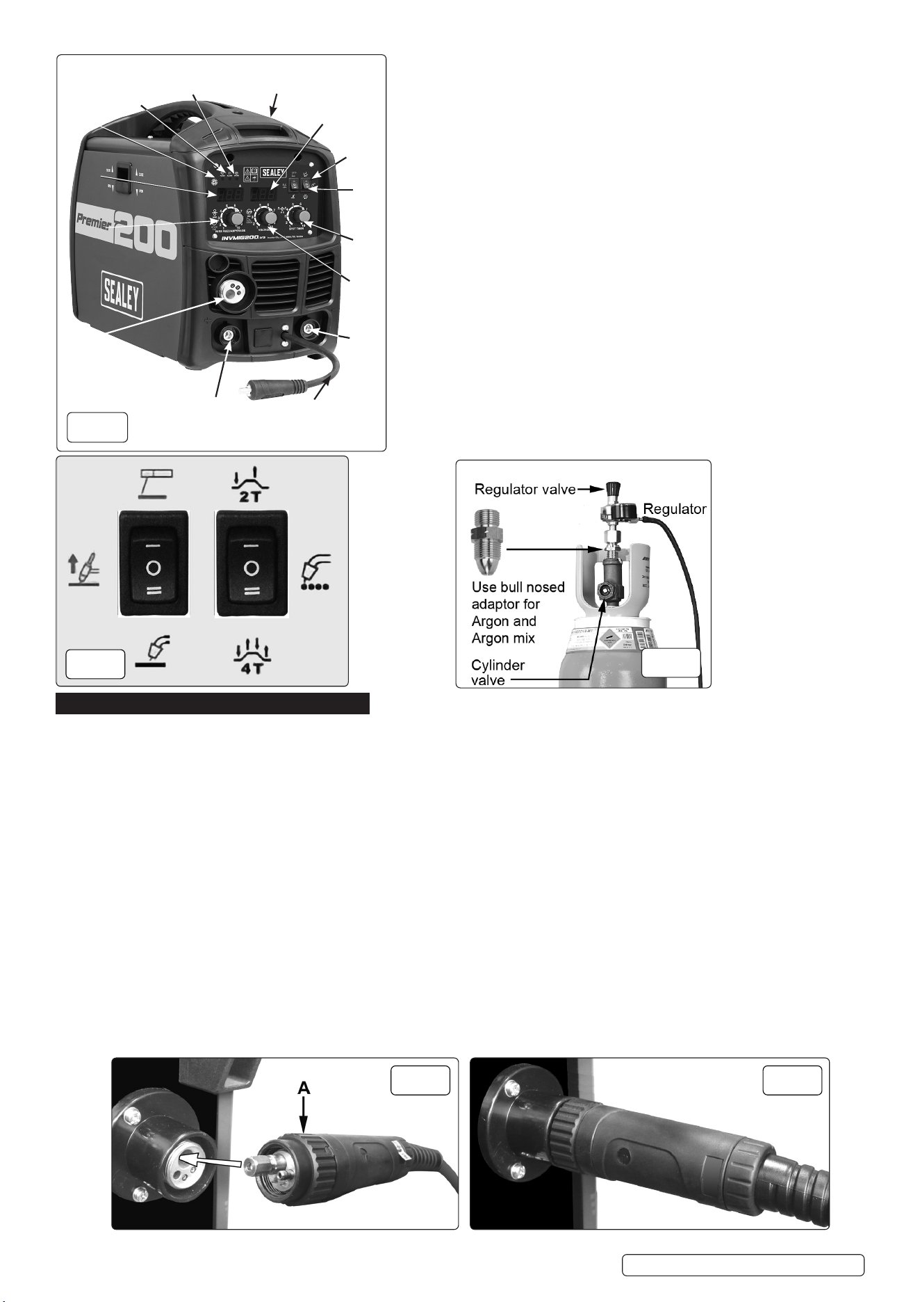
4.1.1. ATTACHING THE REGULATOR (fig.3) Whichever gas you are using it is advisable to ‘crack’ the cylinder valve before attaching the
regulator. This means opening and closing the valve very quickly in order to blow away any dust and dirt that may have accumulated
in the gas outlet. Stand to one side whilst doing this.
4.1.2. CO
2
GAS Ensure that the threads on the gas bottle are undamaged and free of oil and grease before attaching the regulator. (Oil or
grease in the presence of high pressure gases can be explosive.) Ensure that the regulator has an undamaged gasket fitted. The
regulator will screw directly to the threads on the gas bottle. Tighten with a wrench.
4.1.3. ARGON GAS OR ARGON MIXTURES Cylinders containing argon gas and argon mixtures have a female thread and will require the
use of a Bull Nose Adaptor to attach the regulator to the cylinder as indicated in fig.3. Ensure that the threads on the gas bottle are
undamaged and free of oil and grease before attaching the regulator. (Oil or grease in the presence of high pressure gases can be
explosive.) Fit the Bull Nose Adaptor to the cylinder first and tighten with a wrench.
4.1.4. Slide a hose clip over each end of the gas hose supplied. Push one end of the hose onto the regulator outlet and the other end over
the gas inlet spigot on the back of the welder. Tighten the clips to ensure a good seal.
4.1.5. Close the regulator valve by turning it anticlockwise before opening the cylinder valve. Stand to one side when opening.
4.1.6. Set the regulator flow rate to 5-8 litres/min depending on the material to be welded, and whether there are draughts which are strong
enough to disturb the gas flow.
4.2. CONNECTING THE TORCH CABLE TO THE WELDER Align the pins on the Euro connector with the socket on the welder front
panel as shown in g.4. Push the connector into the socket and rotate the locking ring (A) clockwise so that it draws the plug into the
socket as shown in g.5.
NOTE: Damage to torches and cables is not covered by warranty.
Original Language Version
© Jack Sealey Limited
KEY:
1 On/O Switch
2 Work Indicator (lights when an arc is struck).
3 Alarm Indicator
4 Power Indicator
5 Amperage Display
6 Wire Speed Control (MIG/MAG mode)
Amperage Control (TIG/Arc mode)
7 MIG Torch Euro Connector
8 Positive (+) Socket
9 Power Input Lead
10 Negative (-) Socket
11 Voltage Control
12 Spot/Timer Control
13 Mode Selector
14 MIG Trigger Mode Selector
15 Voltage Display
fig.
2
fig.
3
fig.
4
fig.
5
fig.
1
1
4
3
2
5
7
8
9
10
11
12
15
14
13
66
INVMIG200.V3 Issue: 2 (1) 18/01/23
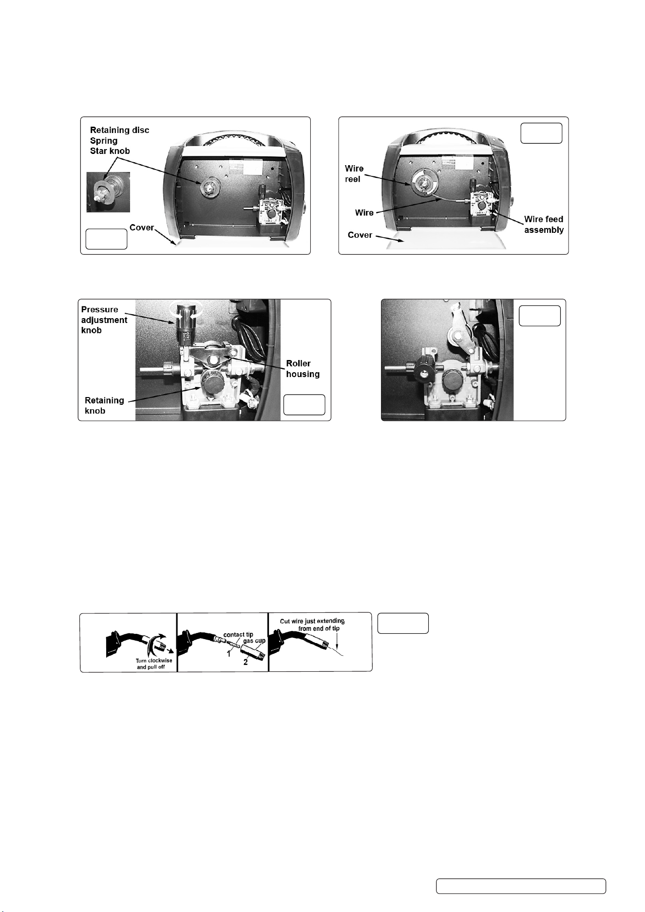
4.3. FITTING A REEL OF WIRE
4.3.1. Open the wire feed compartment cover and unscrew and remove the star knob, spring and retaining disc (fig.6) and place to one side.
4.3.2. Slide the wire reel onto the reel holder (fig.7).
4.3.3. Reattach the star knob, spring and retaining disc and fully tighten (fig.7).
8 DO NOT over tighten.
4.3.4. Ensure that the wire is spooling off from the bottom of the wire reel in the direction of the wire drive unit (fig.7).
NOTE: The larger 5kg wire reel can also be fitted.
4.4. FEEDING THE WIRE THROUGH THE TORCH
WARNING! Ensure that the wire feed roller, the wire guide hose and the contact tip of the torch correspond to the diameter and
type of wire to be used and are tted correctly.
4.4.1. To access the drive mechanism push down on the pressure roller housing (g.8) and pull the pressure adjustment
knob towards you and allow to it to rotate downwards (g.9). Release the pressure roller housing allowing it to
rotate up towards the right.
4.4.2. Ensure that the required feed groove (Ø0.8mm and Ø1.0mm wire) is in line with the wire path. See section 4.6 on how to reverse
or change the roller.
4.4.3. Release the wire from the reel and trim off any bent portion and remove any burrs
WARNING! Prevent the wire from uncoiling by keeping the wire under tension at all times.
4.4.4. Straighten 50-100mm of wire and gently push it through the flexible metal sheathed cable (fig.7) over the feed roller groove and then
into the torch cable liner.
4.4.5. Push down the pressure roller onto the wire feed roller and hold it down then rotate the pressure knob upwards and into the housing
until it snaps into position (fig.8).
4.4.6. Rotate the tension knob to a medium pressure setting between 2 and 3.
NOTE: Turning the knob clockwise increases the pressure and turning anti-clockwise decreases the pressure (fig.8).
WARNING! DO NOT turn gas cup anti-clockwise, as this will damage the internal spring.
d) Unscrew copper contact tip (right hand thread) to remove (g.10).
4.4.7. Check welder is switched off and that the earth clamp is away from the torch tip. Connect the welder to the mains power supply and
select the MIG setting (fig.2) on the mode selector (fig.1.13)
4.4.8. Set the voltage control (fig1.11) to ‘1’.
4.4.9. Set the wire speed knob (fig1.6) to position 5 or 6. Keep the torch cable as straight as possible and press the torch switch. The wire will
feed through the torch.
4.4.10. a) Take torch in left hand, slide the contact tip over the wire and screw back into place.
b) Grasp gas cup in right hand, push onto torch head and turn clockwise only. b) Grasp gas cup in right hand, push onto torch head and turn clockwise only. DO NOTDO NOT turn gas cup anti-clockwise, as this will damage turn gas cup anti-clockwise, as this will damage
the internal spring. the internal spring.
c) Cut wire so that it is just protruding from the cup. c) Cut wire so that it is just protruding from the cup.
4.5. SETTING WIRE TENSION. Adjust the wire tension by rotating the wire tension knob. Turn clockwise to increase the tension and
anticlockwise decrease the tension. See fig.8.
IMPORTANT: IMPORTANT: Too little or too much tension will cause wire feed problems and result in poor welding.Too little or too much tension will cause wire feed problems and result in poor welding.
4.5.1. 4.5.1. Tension between rollers is checked by slowing down the wire between gloved fingers. If top feed roller skids the tension is correct. Use as Tension between rollers is checked by slowing down the wire between gloved fingers. If top feed roller skids the tension is correct. Use as
low a tension as possible; too high a tension could crush the wire and result in a blown fuse. low a tension as possible; too high a tension could crush the wire and result in a blown fuse.
4.6. 4.6. TURNING/CHANGING THE DRIVE ROLLERTURNING/CHANGING THE DRIVE ROLLER.. (See fig.8) (See fig.8) Ensure that the wire diameter (0.6/0.8mm) used is matched by the
correct groove size in the drive wheel and the correct tip size on the torch as well as the correct torch liner. Failure to do so could cause
the wire to slip and/or bind.
Original Language Version
© Jack Sealey Limited
fig.
6
fig.
7
fig.
8
fig.
10
fig.
9
INVMIG200.V3 Issue: 2 (1) 18/01/23
4.6.1. Referring to fig.8, open the wire feed mechanism by pushing the locking/wire tension knob down to the right allowing the pressure
roller carrier to spring up revealing the feed roller.
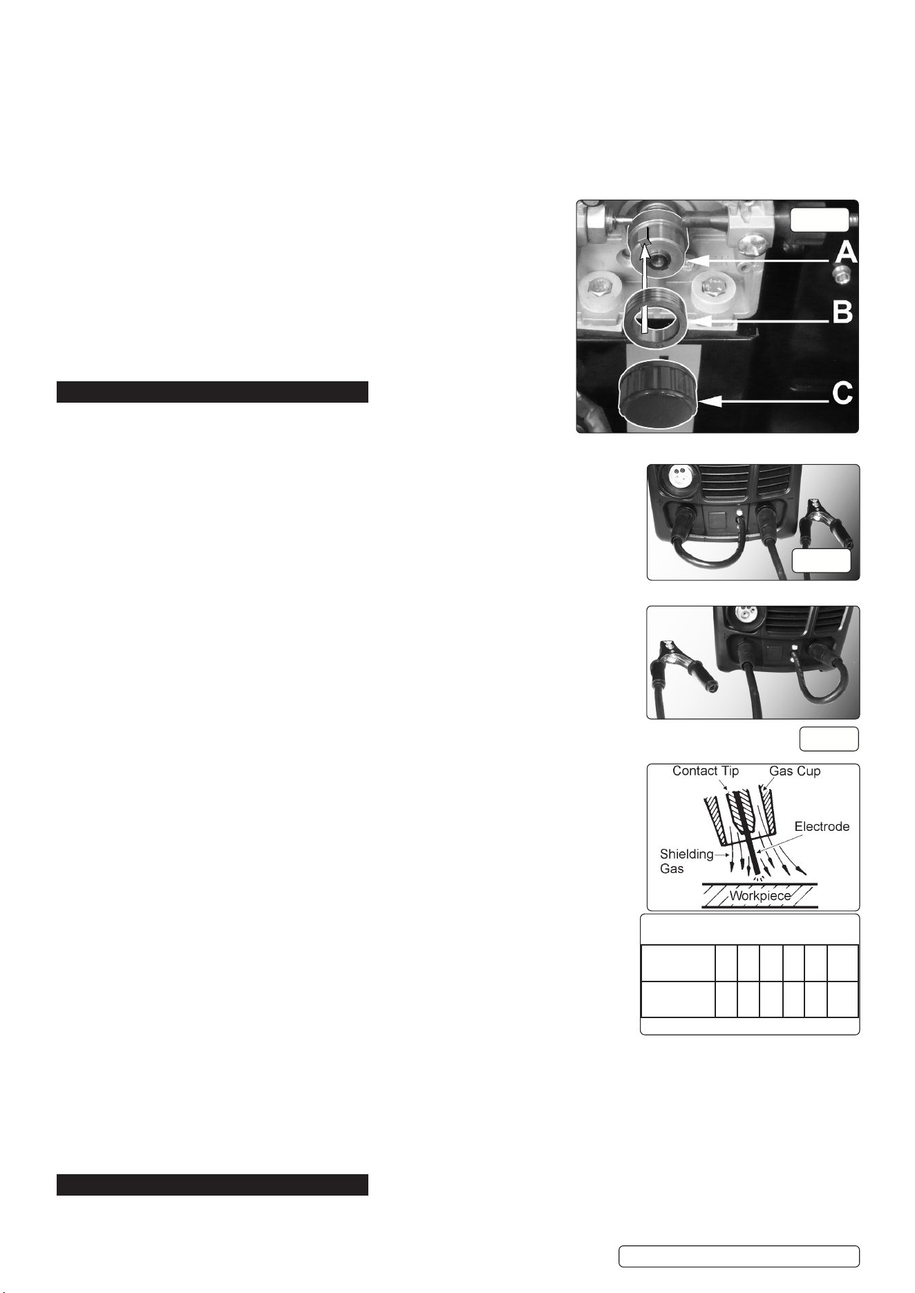
4.6.2. Referring to figure 11, remove knob (C) and put to one side.
4.6.3. The roller carrier (A) is keyed to the main drive shaft and the drive roller (B) is keyed to the carrier, see below. Place a finger onto the end
of the drive shaft to prevent the carrier moving and slide the drive roller off the carrier with your other hand.
4.6.4. The size of each wire feed groove is printed on the edge of the roller on the same side as the groove.
4.6.5. 4.6.5. Turn the roller over to use the other groove or use a roller with different sized grooves as required. The groove to be used should be Turn the roller over to use the other groove or use a roller with different sized grooves as required. The groove to be used should be
positioned furthest away from you to be in line with the drive path. positioned furthest away from you to be in line with the drive path.
4.6.6. Check that the key in the carrier (A) is seated properly in its slot. Ensure that the slot on the inside face of the drive roller (B) is aligned
with the key and slide the roller back onto the carrier.
4.6.7. 4.6.7. Screw the black roller retaining knob (C) back on to the end of the drive shaft and tighten. Screw the black roller retaining knob (C) back on to the end of the drive shaft and tighten.
4.7. CONVERTING TO GASLESS WELDING.
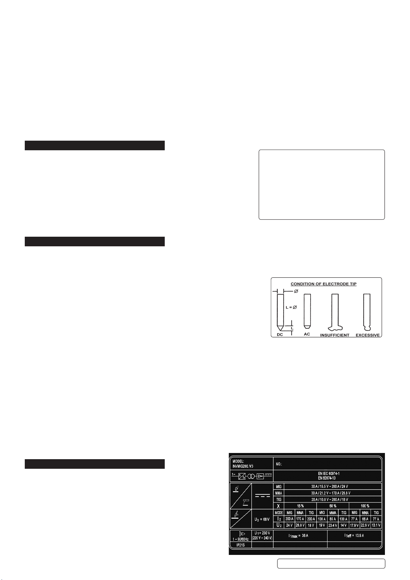
4.7.1. To weld without gas (using ux cored wire) the power input lead (g.1.9) must be
connected to the negative (-) terminal and the earthing cable to the positive (+)
terminal (g.13). Ensure that the machine is switched off and unplugged from the
mains supply before carrying out this task.
4.7.2. Disconnect the gas safely.
4.7.3. Fit a 1.0mm tip to the torch.
4.7.4. Mount the ux cored wire reel and feed it through to the torch.
4.7.5. Set the mode selector to MIG/MAG (fig.2)
5. MIG/MAG WELDING
A spool of welding wire is positioned on the welder’s spool holder and automatically fed through
an insulated liner in the torch to the tip. The torch assembly consists of a switch, liner, gas
hose, and control cable. The switch activates the wire feed roller and the gas flow. Conversely, releasing the switch stops the wire feed and gas
flow. The weld current is transferred to the electrode (the wire) from the contact tip at the end of the torch. A
gas cup fits over the contact tip to direct the gas flow towards the weld ensuring that the arc welding process
is shielded from oxidising air contaminates. The shielding gas also assists heating of the weld materials.
(The welder can also be used in gasless mode using flux cored wire). The torch is connected to the positive
side of a DC rectifier, and the negative clamp is attached to the workpiece.
IMPORTANT: Should you have no welding experience, we recommend you seek training from an
expert source to ensure your personal health & safety. Good MIG welding may be achieved only with
continued, supervised practice.
5.1. PREPARATION FOR WELDING
IMPORTANT: before you commence, make sure the machine is disconnected from the electric
supply. If welding a motor vehicle, disconnect the battery or fit an electronic circuit protector. We
recommend strongly the use of Sealey “prosaf/12v or 24v” in order to protect sophisticated
electronics. Ensure that you have understood the electrical safety instructions in section 1.
5.1.1. Connecting the Power Input Lead. Connect the power input lead (fig 1.9) to the positive (+) socket
(fig1.8) and turn to lock.
5.1.2. Connecting the Earth Lead. Connect the earth lead to the negative (-) socket (g.1.10) and turn
to lock. To ensure a complete circuit, the earth lead must be attached securely to the workpiece
that is to be welded.
a) Best connection is obtained by grinding clean the point of contact on the workpiece before
connecting the earth clamp.
b) The weld area must also be free of paint, rust, grease, etc.
5.1.3. MODE Set the mode selector to MIG/MAG (fig.2).
5.1.4. Voltage Control (fig1.11) Set the control to position 1 or 2 for welding up to 2mm thickness.
Use settings 3, 4, 5, 6. for thicker welds. The selected voltage is displayed by indicator (fig1.15.).
5.1.5. Setting the Wire Speed Control (fig.1.6). In principle, the lower the power required, the slower the
wire speed. See setting chart for voltage and corresponding wire speeds. NOTE: these settings
are only a guide and will vary according to the operator’s experience.
5.1.6. Welding mild steel
To weld mild steel you can use CO
²
gas for most tasks where spatter and the high build up of
weld DO NOT pose a problem. Welding with a long arc reduces penetration and widens the arc.
This in turn results in more spatter. A long welding arc can be appropriate for welding butt joints
in thin materials. Welding with a short arc, at the same weld settings, results in greater
penetration and a narrower weld and reduces the amount of spatter. To achieve a consistent
spatter free and flat weld, you must use an argon/CO
²
mixture.
5.1.7. To weld aluminium use:
● Argon gas,
● 0.8mm Contact Tip (MIG927),
● 0.8mm Aluminium Wire, (MIG/2KAL08).
A clean torch liner is essential, as any contamination of the aluminium wire will produce a poor weld.
5.1.8. Overload Protection. Thermostatic overload protection is provided. When an overload has occurred, the alarm indicator (fig.1.3) will
illuminate. Leave the unit to cool; the thermostat will reset the unit automatically when the temperature has returned within limits.
5.1.9. Trigger Mode (see fig.2). Using the trigger mode selector (fig.1.13), the trigger can be set to 2 touch or 4 touch. 2 touch operates the
welder for as long as the trigger is kept depressed, whereas 4 touch starts the welder operating when the trigger is depressed but will
continue operating when released. The welder will switch off when the trigger is depressed for a second time. The 4 touch setting is
useful to reduce user fatigue when a long weld is required. NOTE: The trigger mode selector only operates in MIG/MAG mode.
6. MMA/ARC WELDING
6.1. For arc welding the selector switch needs to be in the Arc setting (fig.2.1) and the power input lead disconnected.
WARNING! Ensure that the inverter is not plugged into the mains power supply before connecting or disconnecting cables.
Wire: 0.6mm Steel
Argon/CO2 Mix
Voltage
Step:
1 2 3 4 5 6
Wire
Speed:
5 6 7 8 9 10
Settings shown as Guide Only
Original Language Version
© Jack Sealey Limited
fig.12
fig.13
fig.11
INVMIG200.V3 Issue: 2 (1) 18/01/23
For electrical installation, see Safety Instructions (Section 1).
WARNING! Failure to follow the electrical safety instructions may affect the operating performance and could damage the
built-in safety system which, in turn, could result in personal injury or fatality and will invalidate the warranty.
6.2. WELDING CABLE ELECTRODE HOLDER CONNECTION
NOTE: Arc welding cables are not supplied with machine. Sealey part no: INVMMA2 is suitable.
Before connecting cables it is important to refer to the electrode manufacturer’s instructions on the electrode packaging which will
indicate the correct polarity connection for the electrode, together with the most suitable current to use.
6.3. ARC WELDING
When arc welding the electrode holder is normally connected to the “POSITIVE” (+) terminal (fig.1.8).
6.4. WELDING RETURN CABLE- (WORK CLAMP) CONNECTION
The work clamp cable is connected to the terminal not occupied by the electrode holder cable.
The clamp is connected to the workpiece or a metallic work bench. The connection must be as close to the weld as possible.
WARNING! Cable connectors must be turned fully into the sockets to ensure a good electrical contact. Loose connections will cause
overheating, rapid deterioration and loss in efficiency. DO NOT use welding cables over 10m in length. With the exception of a metallic
workbench DO NOT connect the return cable to any metallic structure which is not part of the workpiece, as this will jeopardise weld
quality and may be dangerous.
7. PREPARATION
7.1. The welding current must be regulated according to the diameter of the
electrode in use and the type of joint to be welded (see diameter/current chart to the
right).Welding current is controlled by the amperage control (fig.1.6).
7.2. Further consideration must be given to the location of the weld, for example:
Welds that are performed on a horizontal surface require a higher voltage than
those performed on a vertical or overhead surface.
7.3. The mechanical character of the weld will be determined not only by the current used,
but also by the diameter and quality of the electrode, the length of the arc and the
speed and position of the user. The condition of the electrode is an important factor
and it must never be wet or damp.
7.4. Ensure that the workpiece is correctly secured before operating the inverter.
8. TIG WELDING
8.1. The mode selector should be set to the TIG position (g.2).
8.2. NOTE: The INVMIG200 is not supplied with TIG leads. Sealey part no: INVTIG2 is suitable. If INVTIG2 is used, the braided gas hose
should be connected to the gas bottle: the gas ow is controlled by the valve on the gun (the gas ow is continuous once the valve is
open).
8.3. TIG CONNECTIONS
TIG TORCH CABLE. Connect the torch cable to the negative socket (-) on the front
panel (fig.1.10). WORK CLAMP CABLE. Connect the clamp cable to the positive socket
(+) on front panel (fig.1.8). Please note that the way the welding cables are connected to
the inverter for ordinary MMA welding may be different from the way the cables are
connected for standard TIG welding. Whilst most stick electrodes are connected to the
positive terminal certain types need to be connected to the negative terminal. It is
therefore essential that the user refers to the manufacturer’s instructions for the
electrodes to ensure the correct polarity is selected.
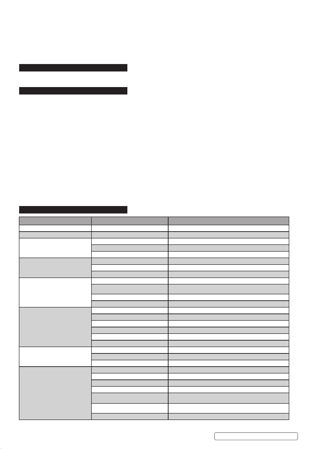
8.4. PREPARATION AND CHOICE OF ELECTRODE. In order to produce a good weld
it is important to choose an electrode of the correct diameter for the current to be used. For a general guide to the settings to be used
with particular diameters of electrodes please refer to the tables below. The electrode will normally protrude from the ceramic nozzle by
2 to 3mm but in order to gain access to inaccessible areas such as internal corners the electrode can be made to protrude by up to 8mm.
The chosen electrode should be sharpened axially on a grinding wheel as indicated in the diagram to the right. The tip should be perfectly
concentric in order to avoid arc deviations. The condition of the electrode should be regularly inspected to maintain it in peak condition.
8.5. PREPARATION OF THE WORKPIECE. For a good weld it is important that the workpiece is cleaned thoroughly so that no oxides, oil,
grease or solvents remain on the surface of the material.
8.6. TIG WELDING PARAMETERS.
9. RATINGS PLATE
The ratings plate on the inverter gives the following data:
1 - Rating of internal protection provided by casing.
2 - Symbol for power supply line: 1= Single-phase AC.
3 - Symbol for internal structure of the welding machine.
4 - Manufacturers Details and Model No.
5 - Manufacturers Serial Number for welding machine identification.
6 - MMA Output.
7- MIG Output
8 - TIG Output
9 - Power Supply
U1: Alternating voltage and power supply frequency of welding
machine. (allowed limit ± 10%)
Electrode Welding Current
(Amps)
Diameter (mm) .....Min .................. Max
1.6 ...........................25 .................... 50
2. ............................. 40 .................... 80
2.5 ........................... 60 .................... 110
3.2 ........................... 80 .................... 160
4. ............................. 120 .................. 200
For Guidance Only
TIG WELDING PARAMETERS FOR STAINLESS STEEL. TIG WELDING PARAMETERS FOR DEOXIDISED COPPER.
Thickness Current Electrode Nozzle Argon Filler Rod Thickness Current Electrode Nozzle Argon Filler Rod
(mm) ( A ) (diam mm) (diam mm) ( L/min ) (diam mm) (mm) ( A ) (diam mm) (diam mm) ( L/min ) (diam mm)
0.5 - 0.8 15 - 30 1 6.5 3 --- 0.5 - 0.8 20 - 30 1 6.5 4 ---
1 30 - 60 1 6.5 3 - 4 1 1 80 - 100 1.6 9.5 6 1.5
1.5 70 -100 1.6 9.5 3 - 4 1.5 1.5 110 - 140 1.6 9.5 6 1.5
2 90 - 110 1.6 9.5 4 1.5 - 2.0
2.5 110 - 130 1.6 9.5 5 1.5 - 2.0
3 120 - 150 1.6 - 2.4 9.5 5 - 6 2 - 3
Original Language Version
© Jack Sealey Limited
INVMIG200.V3 Issue: 2 (1) 18/01/23
I1 max: Maximum current absorbed by the line.
I1 eff: Effective current supplied.
10 - Duty Cycle
U
º
: Maximum no load voltage.
I
²
, U
²
: Current and corresponding normalised voltage that the welding machine can supply during welding.
X: Welding ratio based on a 10 minute duty cycle. 20% indicates 2 minutes welding and 8 minutes rest, 100% indicates continuous
welding.
11 - The EUROPEAN standard relating to the safety and construction of arc welding machines.
10. DUTY CYCLE
When the machine reaches the end of its duty cycle and overheats, the thermostatic switch opens to allow the internal components
to cool. This is denoted by the alarm indicator (g.1.3.) illuminating. Allow the machine to cool and resume use when the light goes out.
11. MAINTENANCE
11.1. WIRE FEED UNIT Check the wire feed unit at regular intervals. The feed roller wire guide plays an important part in obtaining
consistent results. Poor wire feed affects welding. Clean the rollers weekly, especially the feed roller groove, removing all dust
deposits.
11.2. TORCH Protect the torch cable assembly from mechanical wear. Clean the liner from the machine forwards by using compressed
air. If the liner is clogged it must be replaced.
11.2.1. CHANGING FEED ROLLER (See Section 4.6.)
11.3. CONTACT TIP The contact tip is a consumable item and must be replaced when the hole becomes enlarged or oval. The contact
tip MUST be kept free from spatter to ensure an unimpeded flow of gas. Refer to fig.9 for removal and replacement.
11.4. GAS CUP The gas cup must also be kept clean and free from spatter. Build up of spatter inside the gas cup can cause a short
circuit at the contact tip which will result in either the fuse blowing on the printed circuit card, or expensive machine repairs. To keep
the contact tip free from spatter, we recommend the use of Sealey anti-spatter spray (MIG/722308) available from your Sealey Dealer.
11.5. REPLACING THE LINER Wind the wire back on to the spool and secure it. Unscrew the torch from the machine and undo the brass
nut. The liner should now be visible. Pull it out and replace with a new one.
11.6. Remove the casing periodically and, with a low pressure air flow (max 1bar or 15psi), remove dust from inside the machine.
11.7. DO NOT direct compressed air onto the electronic circuit boards, these should be cleaned with a very soft brush.
11.8. Ensure that all electrical connections are tight and check the wiring for damage to the insulation.
11.9. Ensure that the casing is correctly replaced and secured before attempting to use the inverter.
11.10. Keep the outside of the machine clean by wiping with a soft, dry cloth.
11.11. For any other service or maintenance, contact your local Sealey service agent.
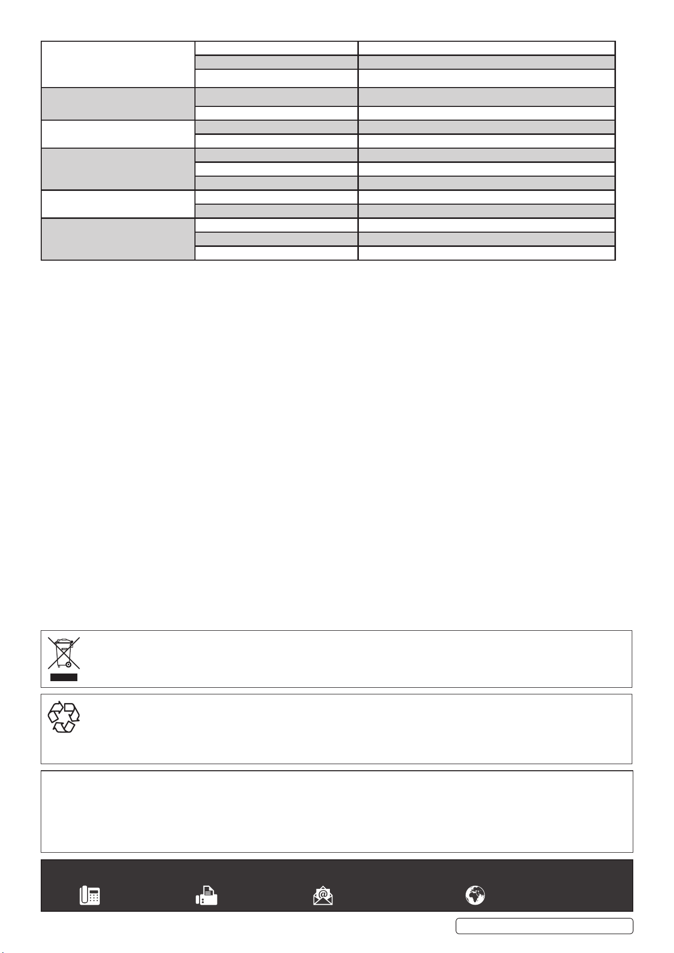
12. TROUBLESHOOTING
Original Language Version
© Jack Sealey Limited
PROBLEM POSSIBLE CAUSE
REMEDY
1. Power source stops Overheating protection activated due to overload Protection automatically resets when transformer has cooled (about 15 min)
2. No weld current Rectifier blown Replace rectifier.
3. No weld current
Bad connection between clamp & workpiece Clean or grind contact surface and weld area
Break in earth lead Repair or replace earth lead.
Break in torch lead Repair or replace torch
4. Feed motor not working, lamp is on
Gear damaged or worn Replace gears. (Contact service agent)
Motor defective Replace motor (Contact service agent)
PCB fault Replace PCB
5. Wire does not feed, feed roller rotates Pressure roller improperly adjusted Adjust tension.
Dirt, copper, dust, etc, has collected in torch liner Clean the liner from the machine forward. Use compressed air. If too much dirt,
replace the liner.
Gas cup (Nozzle) or tip defective Replace gas cup (nozzle) and/or tip. (Section 4)
Deformed wire Check roller tension and adjust it if necessary (Section 4.5)
6. Wire feeds unevenly Dirt, etc, in liner Clean the liner from the machine forward. Use compressed air
Gas cup (Nozzle) or Tip defective Replace gas cup (nozzle) and/or tip. (Section 4).
Gas cup (Nozzle) spattered Clean or replace gas cup (nozzle) (Section 4)
Feed roller groove clogged Clean feed roller.
Feed roller groove deformed Replace feed roller.
Pressure roller tension improper Adjust tension. (Section 4.5)
7. Unstable arc Incorrect settings Check settings.
Impurities in weld area Clean and/or grind workpiece.
Worn or defective gas cup (nozzle) Replace gas cup (nozzle). (Section 4)
8. Porous weld No gas Open gas cylinder, regulate gas flow
Gas cup clogged Clean or replace cup. (nozzle) (Section 4)
Draft blowing away shielding gas Screen off welding site or increase gas flow
Rusty or dirty joints Clean and/or grind workpiece.
Torch too far from or at wrong angle to work The distance from gas cup to workpiece should be 8 to 10mm
Gas leak Check hoses, connections and torch assembly. Press the gas cup into correct
position
Faulty Electrovalve Clean out or replace
INVMIG200.V3 Issue: 2 (1) 18/01/23
Original Language Version
© Jack Sealey Limited
9. Electrode sticking in gas cup (nozzle) Worn or defective gas cup (nozzle) Replace gas cup (nozzle). (Section 4)
Electrode deformed Check roller tension. (Section 4.5)
Wire speed too slow See recommendations for wire speed
10. Irregular weld head Torch incorrectly held Use correct torch angle
Wire weaving in weld pool Check roller tension and adjust as needed. (Section 4.5)
11. Weld bead too narrow and raised Weld current too low Increase power and wire speed.
Weld speed too high Move torch slower and weave a little more
12. Weld bead too wide Weld current too high
Decrease power and wire speed.
Weld speed too low Move torch faster and weave less
Arc too long Bring torch closer to workpiece
13. Poor penetration Weld current too low Increase power and wire speed.
Arc too long Bring torch closer to workpiece
14. Excessive penetration Weld current too high Decrease power and wire speed.
Weld speed too slow
Move torch faster
incorrect distance of torch to workpiece
Torch distance should be 8-10mm
Sealey Group, Kempson Way, Suffolk Business Park, Bury St Edmunds, Suffolk. IP32 7AR
01284 757500 01284 703534 sales@sealey.co.uk www.sealey.co.uk
ENVIRONMENT PROTECTION
Recycle unwanted materials instead of disposing of them as waste. All tools, accessories and packaging should be sorted, taken to
a recycling centre and disposed of in a manner which is compatible with the environment. When the product becomes completely
unserviceable and requires disposal, drain any fluids (if applicable) into approved containers and dispose of the product and fluids
according to local regulations.
Note: It is our policy to continually improve products and as such we reserve the right to alter data, specifications and component parts without prior
notice. Please note that other versions of this product are available. If you require documentation for alternative versions, please email or call
our technical team on technical@sealey.co.uk or 01284 757505.
Important: No Liability is accepted for incorrect use of this product.
Warranty: 3 Year Guarantee - 3 Year parts and labour guarantee on main power transformer for all Arc and MIG welders. Comprises 1 year unconditional
parts and labour followed by a further 2 year parts and labour conditional on registering your purchase with us online at www.sealey.co.uk.
WEEE REGULATIONS
Dispose of this product at the end of its working life in compliance with the EU Directive on Waste Electrical and Electronic Equipment
(WEEE). When the product is no longer required, it must be disposed of in an environmentally protective way. Contact your local solid
waste authority for recycling information.
INVMIG200.V3 Issue: 2 (1) 18/01/23