MIG/TIG & MMA (ARC/STICK) INVERTER
WELDER 200A
MODEL NO: MIG200i
Thank you for purchasing a Sealey product. Manufactured to a high standard, this product will, if used according to these
instructions, and properly maintained, give you years of trouble free performance.
IMPORTANT: PLEASE READ THESE INSTRUCTIONS CAREFULLY. NOTE THE SAFE OPERATIONAL REQUIREMENTS, WARNINGS & CAUTIONS. USE
THE PRODUCT CORRECTLY AND WITH CARE FOR THE PURPOSE FOR WHICH IT IS INTENDED. FAILURE TO DO SO MAY CAUSE DAMAGE AND/OR
PERSONAL INJURY AND WILL INVALIDATE THE WARRANTY. KEEP THESE INSTRUCTIONS SAFE FOR FUTURE USE.
1. SAFETY
1.1. ELECTRICAL SAFETY
WARNING! It is the user’s responsibility to check the following:
9 Check all electrical equipment and appliances to ensure that they are safe before using.
9 Inspect power supply leads, plugs and all electrical connections for wear and damage.
9 Ensure that the insulation on all cables and on the appliance is safe before connecting it to the power supply.
8 DO NOT use worn or damaged cables, plugs or connectors.
9 Ensure that any faulty item is repaired or is replaced immediately by a qualified electrician.
9 If the cable or plug is damaged during use, switch off the electricity supply and remove from use.
9 Ensure that repairs are carried out by a qualified electrician.
9 Sealey recommend that an RCD (Residual Current Device) is used with all electrical products.
Important: Ensure that the voltage rating on the appliance suits the power supply to be used and that the plug is fitted with the correct
fuse.
8 DO NOT pull or carry the appliance by the power cable.
8 DO NOT pull the plug from the socket by the cable.
1.1.1. We recommend connection to a supply with a type C breaker. If in doubt you must contact a qualified electrician to ensure that a suitably
rated supply is available.
WARNING! Be very cautious if using a petrol or diesel generator. The generator must be stable with regard to frequency (Hz), voltage
and wave form. The output must be higher than the power (kVA) of the inverter. The generator must also be self regulating. If any A.M.
feature is not respected the working of the regulation card may be affected. Use of a generator without a regulator may be dangerous
and will invalidate your inverter warranty.
1.2. GENERAL SAFETY
1.2.1. OPERATOR SAFETY
9 Operators must receive adequate training before using the inverter.
9 Remove ill fitting clothing, remove ties, watches, rings and other loose jewellery and contain long hair.
8 DO NOT operate the inverter while under the influence of drugs, alcohol or intoxicating medication, or if tired.
9 Stand correctly keeping a good footing and balance, ensure that the floor is not slippery and wear non-slip shoes.
9 Keep unauthorised persons away from the work area. Any persons working within the area must wear the same protective items.
9 Avoid oily greasy clothing. A spark may ignite them.
8 DO NOT touch the work piece close to the weld as it will be very hot. Allow to cool.
8 DO NOT touch the electrode holder immediately after use. Allow the electrode holder to cool.
9 Wear safety welding gauntlets.
WARNING! DO NOT place the welding power source on a tilted plane as this may lead to the unit toppling over.
9 The output is rated at an ambient temperature of 20°C and the welding time may be reduced at higher temperatures.
9 Risk of electric shock: Electric shock from welding electrode can kill. DO NOT weld in the rain or snow. Wear dry insulating gloves.
8 DO NOT touch electrode with bare hands. DO NOT wear wet or damaged gloves. Protect yourself from electric shock by insulating
yourself from workpiece. DO NOT open the equipment enclosure.
9 Use genuine parts and accessories only. Unapproved parts may be dangerous and will invalidate the warranty.
▲ DANGER! DO NOT weld near flammable materials, solids, liquids, or gases, and DO NOT weld containers or pipes which have held
flammable materials or gases, liquids or solids. Avoid operating on materials cleaned with chlorinated solvents or near such solvents.
8 DO NOT use power source for pipe thawing.
▲ DANGER! Vapours from chlorinated solvents (such as de-greasers) can be decomposed by the heat of the arc to form PHOSGENE,
a highly toxic gas, and other lung and eye irritating products.
The ultraviolet (radiant) energy of the arc can also decompose trichloroethane and perchloroethylene vapours to form phosgene.
Refer to
instruction
manual
Hot surfaces Do not use in
the vicinity of a
pacemaker
Wear a
welding mask
Wear
protective
gloves
Wear safety
footwear
Wear
protective
clothing
Welding sparks
can cause
explosions or re
Arc rays can burn
eyes and injure
skin
Breathing welding fumes
can be hazardous to your
health
MIG200i Issue 2 10/01/25
Original Language Version
© Jack Sealey Limited
Electrical
shock hazard

8 DO NOT weld where solvent vapours can be drawn into the welding or cutting atmosphere or where the radiant energy can penetrate
to atmospheres containing even minute amounts of trichloroethylene or perchloroethylene.
9 Prevent dangerous conditions arising by providing adequate ventilation. NEVER ventilate with oxygen.
▲ DANGER! Lead-, cadmium-, zinc-, mercury- and beryllium-, bearing materials, when welded (or cut) may produce harmful
concentrations of toxic fumes. Adequate local exhaust ventilation must be used, or each person in the area as well as the operator
must wear an air- supplied respirator.
For beryllium, both must be used. Metals coated with or containing materials that emit toxic fumes should not be heated unless coating is
removed from the work surface, the area is well ventilated, or the operator wears an air-supplied respirator.
8 DO NOT work in an unventilated confined space. If necessary, wear an air-supplied respirator.
WARNING! Generator engine exhaust must be vented to the outside air. Carbon monoxide can kill.
9 When not in use store the welder in a safe, dry, childproof area.
1.2.2. CABLE CONNECTIONS
9 Keep the inverter and cables in good working order and condition. Take immediate action to repair or replace damaged parts.
9 Ensure that there is no obstruction to the flow of clean, cool air and ensure that there are no conductive dusts, corrosive vapours or
humidity which could enter the inverter and cause serious damage.
1.2.3. PROTECTION FROM ARC
WARNING! Use welding head shield to protect eyes and avoid exposing skin to ultraviolet rays given off by electric arc. Looking at an arc
momentarily with unprotected eyes (particularly a high intensity gas-shielded arc) can cause a retinal burn that may leave a permanent
dark area in the field of vision.
9 Before welding whilst wearing contact lenses, seek advice from your optician.
9 Avoid unintentional contact with workpiece. Accidental or uncontrolled arcing on the electrode holder may be dangerous.
8 DO NOT hit the electrode on the workpiece, this may damage the electrode and make strike-up difficult.
9 Wear safety welding gauntlets.
1.2.4. WELDING ENVIRONMENT
9 Locate the inverter in a suitable work area.
9 Keep the work area clean and tidy and free from unrelated materials. Also ensure that the work area has adequate lighting.
8 DO NOT get inverter wet or use in damp or wet locations or areas where there is condensation.
9 First aid facilities and a qualified first aid person should be available during welding operations.
9 For production welding, a separate room or enclosed bay should be provided. In open areas, surround the operation with low reflective,
non-combustible screens or panels. Allow for free air circulation, particularly at floor level. Provide face shields for all persons who will be
looking directly at the weld. Before starting to weld, make sure that screen or bay doors are closed.
9 Always ensure that there is full free air circulating around the outer casing of the machine, and that the louvres are unobstructed.
1.2.5. FIRE HAZARD
WARNING! Be aware that flying sparks or falling slag can pass through cracks, along pipes, through windows or doors, and through wall or
floor openings, out of sight of the operator. Sparks and slag can fly 10m.
8 DO NOT weld within 10 metres of combustible materials (including building construction materials).
8 DO NOT weld adjacent to openings (concealed or visible) in floors or walls within 10m that can expose combustibles to sparks.
8 DO NOT weld near to walls, ceilings, roofs or metal partitions where there are combustibles that can be ignited by radiant or conducted
heat.
9 Have suitable re extinguishing equipment available and someone to use it during welding operations and for some time after welding
ceases. After work is done, check that area is free of sparks, glowing embers, and ames.
1.2.6. PRODUCT CARE & MAINTENANCE
8 DO NOT attempt to fit any unapproved electrode holder, components, or parts to the inverter unit.
9 Keep the inverter clean for best and safest performance.
WARNING! If the case is opened for maintenance or repair, wait 10-15 seconds after the unit is switched off for the capacitor to discharge.
1.2.7. TRANSPORTATION
The machine should be transported in an upright position.
NOTE: Always move the inverter by lifting it from its handle. Never pull it by the welding gun or cables.
1.2.8. ENVIRONMENT
The machine is suitable for both indoor and outdoor use. But it should be protected from heavy rain and sunshine. Store the machine in
a dry and clean environment and protect it from sand and dust during use and storage. The recommended operating temperature
range -20⁰C-+40⁰C.
Place the machine in such a way that it does not come in contact with hot surfaces, sparks and spatters.
Make sure the air flow in the machine is unrestricted.
1.2.9. WELDING CABLES
The welding cables should be kept as short as possible and should be positioned close together, close to the oor level.
1.2.10. EARTHING OF THE WORK PIECE
Where the work piece is not bonded to earth for electrical safety, nor connected to earth because of its size and position, e.g. ship’s
hull or building steel work, a connection bonding the work piece to earth may reduce emissions in some. But not all instances. Care
should be taken to prevent the earthing of the work piece increasing the risk of injury to users, or damage to other electrical
equipment. Where necessary, the connection of the work piece to earth should be made by direct connection to the work piece.
WARNING! Hot metal such as electrode stubs and workpieces should never be handled without gloves.
Original Language Version
© Jack Sealey Limited
MIG200i Issue 2 10/01/25
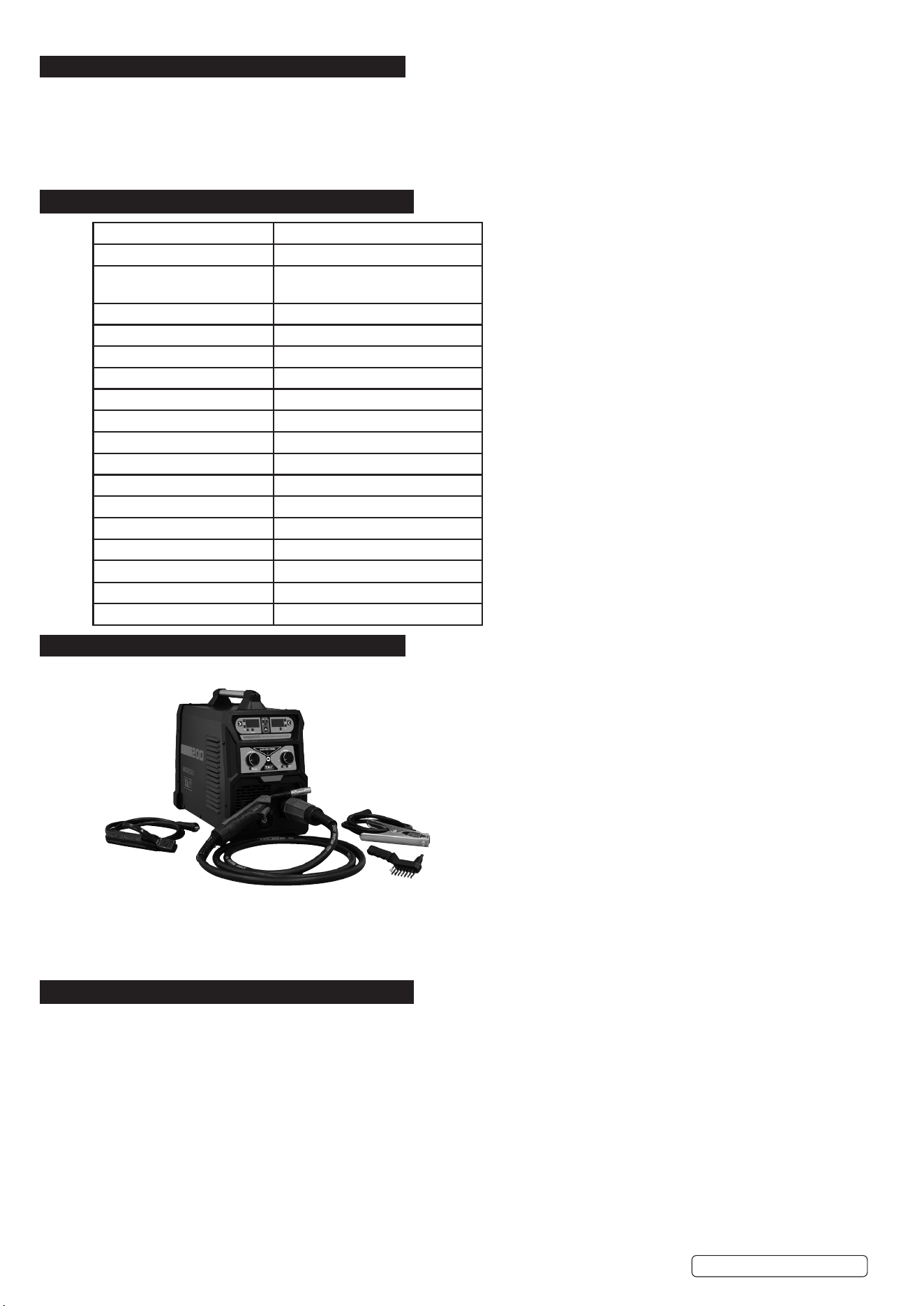
2. INTRODUCTION
IGBT Inverter fan-cooled DC power supply for MIG/TIG and MMA/ARC welding applications up to 200A. Multi-functional welder bringing
together MIG/TIG and MMA application all into one compact unit ideal for workshops, garages, bodyshops and mobile technicians. Ultra-
compact and lightweight unit weighing just 11.1kg approx. Supplied with handle making this unit highly portable allowing the welder to be
taken to the job at hand. Featuring hot start, anti-stick, forced air cooling and thermal cut out protection. Unit can MIG weld using 5kg Ø0.8/
Ø0.9/Ø1.0mm solid wire and ux cored MIG wire, MMA/ARC weld Ø1.6 up to Ø4.0mm electrode. Supplied with non-live MIG torch 2.8m,
1.4m earth cable/clamp, 1.6m electrode holder.
3. SPECIFICATION
4. CONTENTS
* To achieve maximum power 16A supply may be required.
5. OPERATION
WARNING! Ensure that the inverter is not plugged into the mains power supply before connecting or disconnecting cables. For electrical
installation, see Safety Instructions (Section 1).
WARNING! Failure to follow the electrical safety instructions may affect the operating performance and could damage the built-in safety
system which, in turn, could result in personal injury or fatality and will invalidate the warranty.
5.1. WELDING CABLE “ELECTRODE HOLDER” CONNECTION
5.1.1. Before connecting cables it is important to refer to the electrode manufacturer’s instructions on the electrode packaging which will indicate the
correct polarity connection for the electrode, together with the most suitable current to use.
5.1.2. The welding cables should be kept as short as possible and should be positioned close together,running at or close to the floor level.
5.1.3. EARTHING OF THE WORK PIECE
5.1.4. Where the work piece is not bonded to earth for electrical safety, nor connected to earth because of its size and position, e.g. a ship’s hull or
building steel work, a connection bonding the work piece to earth may reduce emissions in some, but not all instances. Care should be taken
to prevent the earthing of the work piece increasing the risk of injury to users, or damage to other electrical equipment. Where necessary, the
connection of the work piece to earth should be made by direct connection to the work piece. But in some countries where direct connection is
not permitted, the bonding should be achieved by suitable capacitance, selected according to national regulations.
Model No MIG200i
Absorbed Power 7.7kw
Applicable Standards EN IEC 60974-10:2021
EN IEC 60974-1:2018+A1:2019
Class of insulation H
Duty Cycle Mig 200A @ 60%, 154A @ 100%
Duty Cycle MMA 170A @ 60%, 131A @ 100%
Duty Cycle TIG 170% @ 60%, 131A @ 100%
Eciency of the product: 85%
Electrode Capacity Ø1.6-4mm
EMC classication Class A
IP Rating IP21S
Nett Weight 11.1kg
Plug Type Bare Wire
Pollution Degree 3
Power Supply Cable Length 2m
Static Characteristic Drooping
Welding Current 50-200A
Wire Capacity 5kg
Original Language Version
© Jack Sealey Limited
Earth Clamp
Mig Torch
Wire brush and
tapping hammer
Stick torch
MIG200i Issue 2 10/01/25
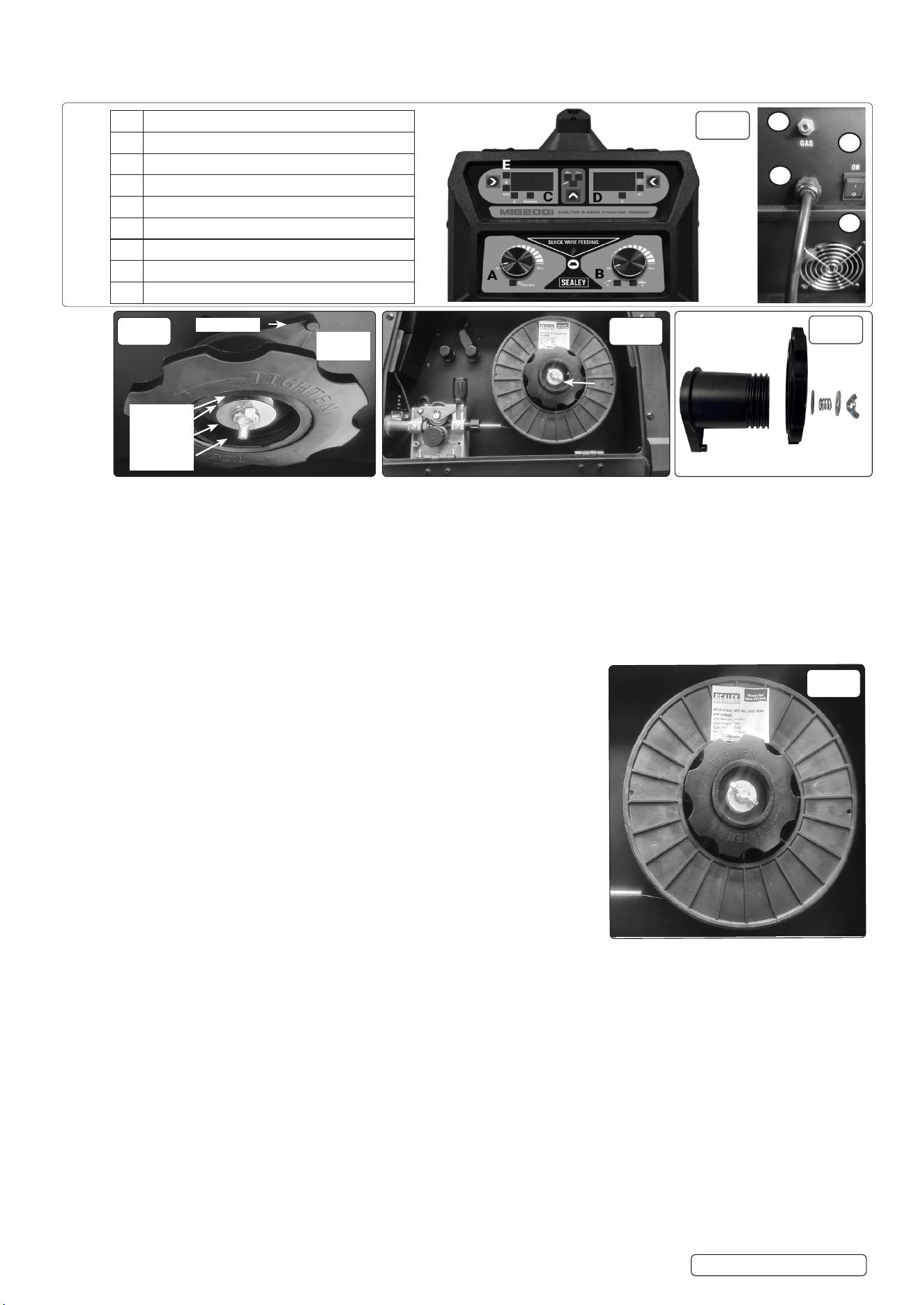
5.1.5. FRONT/ REAR PANELS see Fig.1
5.1.6. Rocker switch. Turns mains power on and o.
NOTE: Familiarize yourself with the location and purpose of the controls on this unit before attempting to operate.
5.2. FITTING A 5KG REEL OF WIRE
5.2.1. Open the left side of the case by pulling down both side casing catches.
5.2.2. Ensure that the wire diameter used, is matched by the correct groove size in the drive wheel and the correct tip size on the torch as well as
the correct torch liner. Failure to do this could cause the wire to slip and/or bind.
5.2.3. Remove nut Fig.3 (A) from the end of the spindle. Remove retaining assembly and spring and washers. Unscrew locking knob and slide
spacer off from spindle.
5.2.4. Slide the reel of wire over the spindle and hold it against the back plate so that the hole in the reel rests on the clutch pin. (See Fig.2.).
5.2.5. Ensure that the wire is coming off the bottom of the reel in the direction of the wire drive unit as shown in Fig.5.
5.2.6. Slide spacer onto the spindle and screw the locking knob back into place. (See Fig.4). Replace retaining assembly and spring into place.
5.2.7. Place the retaining assembly back into the spindle. Re-tighten bolt (A).
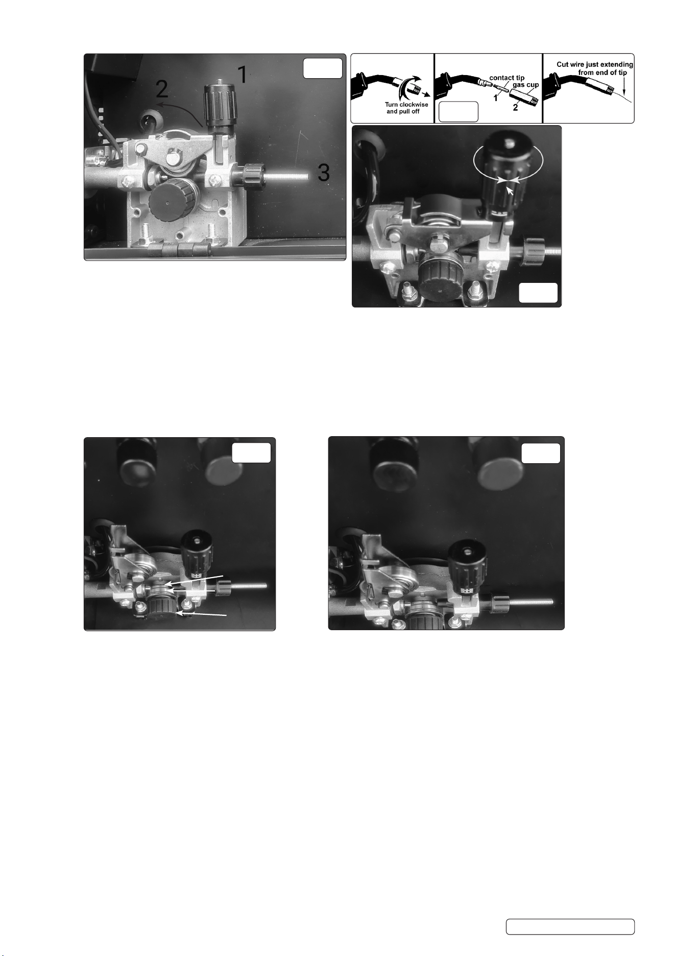
5.3. FEED WIRE THROUGH TO TORCH
5.3.1. Open the wire feed mechanism by pushing the locking/wire tension knob
(1) down to the right allowing the pressure roller carrier (2) to spring up
revealing the feed roller as shown in Fig.6. Ensure that the required feed groove (0.6 or
0.8) is in line with the wire path. See Section 5.6 on how to reverse or change the roller.
5.3.2. Release the wire from the reel and cut off any bent portion ensuring that there are no burrs
left on the end of the wire. Keep the wire under tension at all times to prevent it uncoiling.
5.3.3. Straighten about 40-50mm of wire and gently push it through the flexible metal sheathed
cable, Fig.6 (3) and through the 6 or 8mm feed roller groove and on into the torch cable
liner.
5.3.4. Push down the pressure roller carrier onto the wire feed roller and hold it down. Lift up
the locking/wire tension knob so that it enters the slot in the pressure roller carrier
and snaps into the indent in its top surface. See Fig.8. Rotate the tension knob to a
medium setting i.e. between 2 and 3.
5.3.5. 5.3.5. RRemove gas cup (Fig.7-2) and contact tip (1) from end of torch as follows:emove gas cup (Fig.7-2) and contact tip (1) from end of torch as follows:
a) Take torch in left hand with the torch tip facing to the right.
b) Grasp gas cup firmly in your right hand.
c) Turn gas cup clockwise only and pull it off end of torch tip.
WARNING! DO NOT turn gas cup anti-clockwise, as this will damage the internal spring.
dd) Unscrew copper contact tip (right hand thread) to remove.) Unscrew copper contact tip (right hand thread) to remove.
Check welder is switched off 0, and that the earth clamp is away from the torch tip. Connect the welder to the mains power supply and set
the voltage switch to one.
Set the wire speed knob to position 5 or 6. Keep the torch cable as straight as possible and press the torch switch. The wire will feed
through the torch.
When the wire has fed through, switch welder off, unplug from mains.
a) Take torch in left hand, slide the contact tip over the wire and screw back into place.
b) Grasp gas cup in right hand, push onto torch head and turn clockwise only.
8 DO NOT turn gas cup anti-clockwise, as this will damage the internal spring.
c). Cut wire so that it is just protruding from the cup.
A Wire feed speed adjustment
B Current adjustment dial
C Wire speed
D Working voltage and 2T/4T switching display
E Overheat light
1 ON/OFF switch
2 Gas connection
3 Power Cable
4 Fan cover
Front
Rear
Front
Rear
Fig. 1
1
2
3
4
Original Language Version
© Jack Sealey Limited
Fig. 2
Washer
Spring
Washer
Wing nut
Clutch pin
Locking
Knob
Fig. 4
A
Fig. 5
Fig. 3
MIG200i Issue 2 10/01/25
..
5.4. SETTING WIRE TENSION
5.4.1. Adjust the wire tension by rotating the wire tension knob.
Turn clockwise to increase the tension and anticlockwise
to decrease the tension. See (1) in Fig.8.
IMPORTANT: Too little or too much tension will cause problematic wire feed and result in poor welding.
5.4.2. Tension between rollers is checked by slowing down the wire between gloved fingers. If top feed roller skids the tension is correct. Use as
low a tension as possible, too high a tension will disfigure wire and result in a blown fuse.
5.5. CLUTCH ADJUSTMENT
NOTE: It is essential that the clutch is adjusted correctly.
5.5.1. 5.5.1. Once the wire is fed through the torch, switch on the machine and set the wire speed to maximum. Once the wire is fed through the torch, switch on the machine and set the wire speed to maximum.
5.5.2. 5.5.2. Depress torch switch and release quickly. If the spool overruns it indicates that the clutch is too loose. Depress torch switch and release quickly. If the spool overruns it indicates that the clutch is too loose.
5.5.3. 5.5.3. Tighten the clutch bolt located in the centre of the wire spool holder hand tight (Fig.5-A) and test the machine as above until the wire Tighten the clutch bolt located in the centre of the wire spool holder hand tight (Fig.5-A) and test the machine as above until the wire
stops over running.
NOTE: DO NOT over tighten the clutch as this will cause wire feed problems and strain the motor.
5.6. TURNING/CHANGING THE DRIVE ROLLER (See Fig.9)
5.6.1. Ensure that the wire diameter used, is matched by the correct groove size in the drive roller and the correct tip size on the torch as well as
the correct torch liner. Failure to do this could cause the wire to slip and/or bind.
5.6.2. Referring to Fig.6, open the wire feed mechanism by pushing the locking/wire tension knob (1) down to the right allowing the pressure
roller carrier (2) to spring up revealing the feed roller.
5.6.3. Referring to Fig.9, loosen and unscrew the black feed roller retaining knob (C) and put to one side.
5.6.4. The roller carrier (A) is keyed to the main drive shaft and the drive roller (B) is keyed to the carrier. Place a finger onto the end of the drive
shaft to prevent the carrier moving and slide the drive roller off the carrier with your other hand.
5.6.5. The size of each wire feed groove is printed on the edge of the roller on the same side as the groove.
5.6.6. 5.6.6. TTurn the roller over to use the other groove or use a roller with different sized grooves as required. The groove to be used should be urn the roller over to use the other groove or use a roller with different sized grooves as required. The groove to be used should be
positioned furthest away from you to be in line with the drive path.positioned furthest away from you to be in line with the drive path.
5.6.7. 5.6.7. CCheck that the key in the carrier (A) is properly seated in its slot. Ensure that the slot on the inside face of the drive roller (B) is aligned heck that the key in the carrier (A) is properly seated in its slot. Ensure that the slot on the inside face of the drive roller (B) is aligned
with the key and slide the roller back onto the carrier. with the key and slide the roller back onto the carrier.
5.6.8. 5.6.8. SScrew the black roller retaining knob (C) back on to the end of the drive shaft and tighten.crew the black roller retaining knob (C) back on to the end of the drive shaft and tighten.
Fig. 6
Fig. 7
Fig. 8
Original Language Version
© Jack Sealey Limited
1
Fig. 9
Fig.10
-- ++
A B
A
B
C
MIG200i Issue 2 10/01/25
Original Language Version
© Jack Sealey Limited
A Wire feed speed adjustment
B Current adjustment dial
C Wire speed
D Working voltage and 2T/4T switching display
E Overheat light
1 ON/OFF switch
2 Gas connection
3 Power Cable
4 Fan cover
Front
Rear
Fig. 1
Front
Rear
1
4
2
3
5.7. MIG WELDING
5.7.1. Fig.1 A shows wire feed speed control, Fig.1 B shows volt adjustment. Before you press torch switch, Fig.1C shows wire feed speed, Fig.1
D shows pre-set volt, you can select 2T or 4T. (Note: 2T means when you press the torch switch the machine works, when you release the
torch switch, the machine stops working. 4T means when you press the torch switch, the machine works continuously, when you release
the torch switch, machine keeps working; and when pressing the torch switch a second time the machine will stop working.)
NOTE: When you press torch switch, C shows real time current, Fig.1 D shows real time working volts.
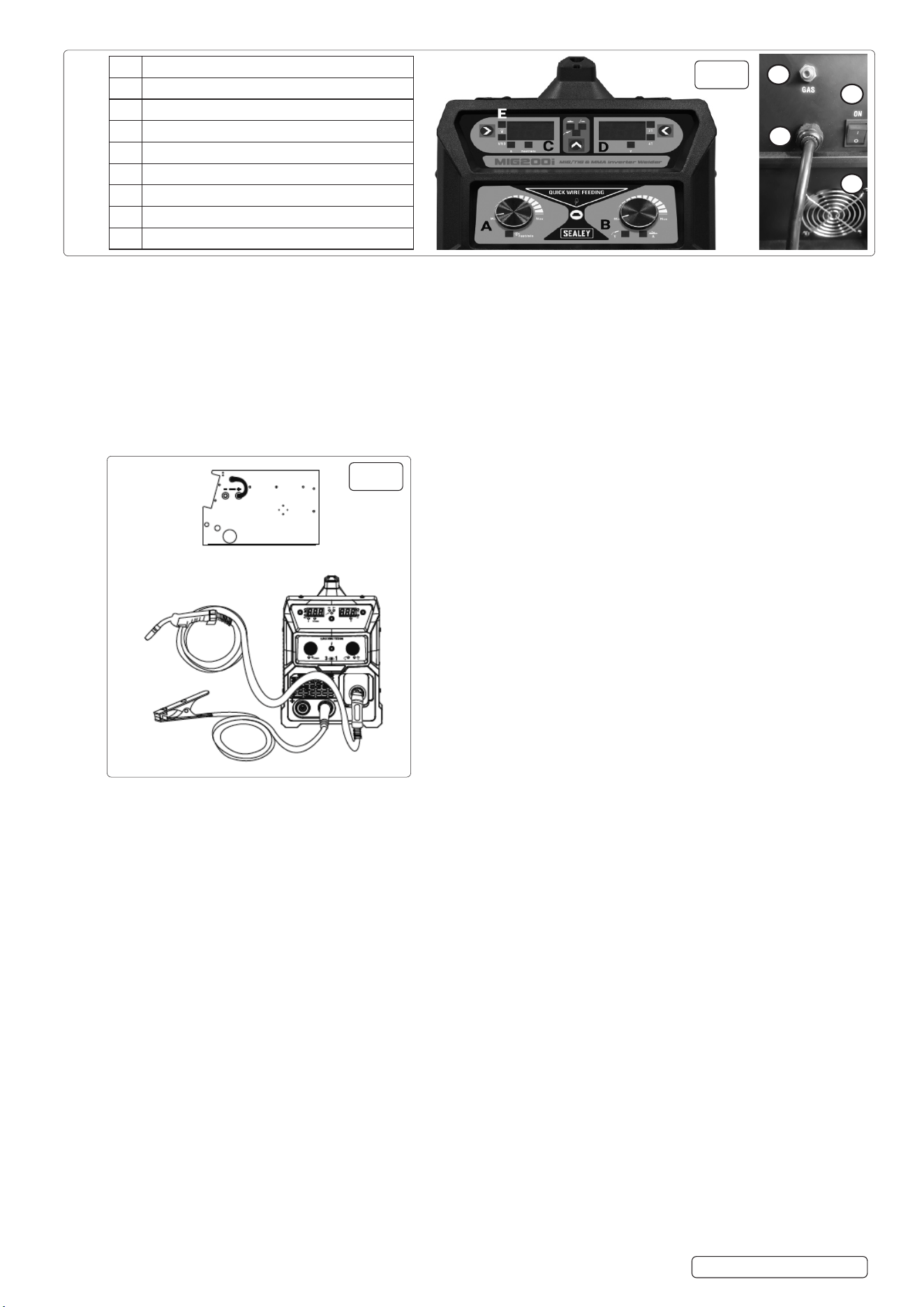
5.8. MIG SETUP (Fig.11)
5.8.1. Solid Wire Setup.
5.8.2. This set up is known as DC Electrode Positive (straight polarity).
5.8.3. This is commonly used for DC MIG welding.
5.8.4. When installing wire, remove contact tip from MIG gun first, after wire is sent out, put the contact tip back.
5.8.5. FLUX-CORED WIRE SETUP (Fig.12)
5.8.6. This set up is known as DC Electrode Negative (reverse polarity).This is commonly used for DC Flux Core welding.
5.8.7. Wh e n i n s t a l l i n g w i r e , r e m o v e c o n t a c t t i p f r o m M I G g u n r s t , a f t e r w i r e i s s e n t o u t , p u t t h e c o n t a c t t i p b a c k .
NOTE: Connect the earth clamp to the positive polarity..
5.8.8. THE MIG SOLID WIRE AND FLUX CORE PROCESSES UTILISE DIFFERENT POLARITIES.
5.8.9. To change between them follow these instructions:
5.8.10. Make sure the machine is unplugged from the power receptacle.
5.8.11. Open the door to the machine.
5.8.12. Remove the polarity terminal knobs.
5.8.13. Set up the polarity (as per graphics above) by removing the leads from the terminals and reversing them if necessary.
5.8.14. Replace the polarity terminal knobs.
NOTE: ENSURE THAT POLARITY TERMINAL KNOBS ARE TIGHTLY SECURED AND THAT THERE IS NO CONNECTION
BETWEEN THE CABLES.
Fig.11
Fig.12
MIG200i Issue 2 10/01/25
Original Language Version
© Jack Sealey Limited
5.8.15. GAS CONNECTOR
5.8.16. When using the MIG welding process (solid wire) a shielding gas is required. Familiarise yourself with the location of the “Back Panel”
tapered nozzle gas connector before attempting to operate (Fig.1)
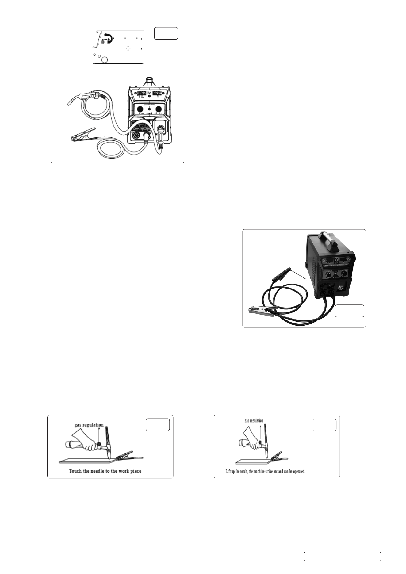
5.8.17. STICK WELDING
5.8.18. Fig.1 A is now inoperative, Fig.1 B shows amp adjustment, Fig.1C shows current, Fig.1 D shows volts. You can choose to turn on the VRD or
as required.
5.8.19. STICK SETUP Fig.12A
5.8.20. Connect the electrode holder to the positive polarity and the earth clamp to the negative polarity, which is commonly used for STICK
welding on most materials, such as low carbon steel and low alloy steel.
5.8.21. STICK WELDING
5.8.22. Turn on power switch on back panel, fan now operates.
5.8.23. Make sure function switch of front panel is on “correct” position which is stick
welding.
5.8.24. Make sure welding current is adequate for thickness of work piece.
5.8.25. TIG WELDING
5.8.26. Fig.1 A is now inoperative, Fig.1 B shows amp adjustment, Fig.1 C shows current,
Fig.1 D shows volts. In the meantime, VRD light is on.
5.8.27. TIG SETUP
5.8.28. Connect the earth clamp to the positive polarity, and the TIG welding torch to the
negative polarity.
5.8.29. Turn on the power switch on the back panel, digital current meter is normal, fan
starts.
5.8.30. Open the valve of argon cylinder, adjust the volume of regulator and adjust.
5.8.31. Turn on the flow switch on the TIG gun, and check the argon gas is flowing from
the torch burner.
5.8.32. Set suitable welding current and make sure welding current is adequate to the
thickness of work piece and process demand.
5.8.33. Touch the tungsten needle to the work piece and then lift up, burn and strike arc. The inverter welder can be now operated.
NOTE: When welding is complete, argon gas will still flow out for several seconds in order to protect welding spot before its cooled down
. So torch must be kept in welding position until flame is extinguished.
5.8.34. TIG USE OF TORCH (Not included.)
5.8.35. PREPARATION FOR TIG
5.8.36. Install tungsten needle, needle reach 0.08-0.2inch
5.8.37. See Fig.13
5.8.38. Lift up the torch, the machine strike arc and can be operated see Fig.14.
Stick set up.
Fig.14
Fig.13
Fig.12
Fig.12A
MIG200i Issue 2 10/01/25
6. MAINTENANCE
6.1. DAILY MAINTENANCE
WARNING! Before removing the welding machine panels switch off the machine and disconnect it from the mains power supply. Wait 10-
15 seconds after the unit is switched off for the capacitor to discharge.
WARNING! Before carrying out routine maintenance, switch off the welding and disconnect it from the mains power supply.
WARNING! If the welding machine is not functioning properly repairs should be carried out only and by authorised service engineers.
6.1.1. Remove welding splatter from the welding gun’s tip and check the condition of the parts. Replace any damaged parts immediately.
6.1.2. Check that the insulation tips of the welding gun’s neck are undamaged and in its place. Change any damaged parts.
6.1.3. Check the tightness of the welding gun’s and earthing cable’s connection.
6.1.4. Check the supply voltage and welding cable and replace faulty cables.
6.2. Periodically remove the casing and, with a low pressure air flow (max. 1bar or 15psi), remove dust from inside the machine.
8 DO NOT direct compressed air onto the electronic circuit boards, these should be cleaned with a very soft brush.
6.3. Ensure that all electrical connections are tight and check the wiring for damage to the insulation.
6.4. Ensure that the casing is correctly replaced and secured before attempting to use the inverter.
6.5. Keep the outside of the machine clean by wiping with a soft, dry cloth.
6.6. For any other service or maintenance, contact your local Sealey service agent.
6.7. Put the machine into the original packing in dry location if it is not to be used for a long time.
6.8. MAINTENANCE OF THE EQUIPMENT
6.8.1. The equipment should be routinely maintained according to these instructions. All access and service covers should be closed and
properly fastened when the welding equipment is in operation.
The welding equipment should not be modified in any way except for those changes and adjustments covered in these instructions. In
particular, the spark gaps of any arc striking and stabilising devices should be adjusted and maintained according to their instructions.
7. TROUBLESHOOTING
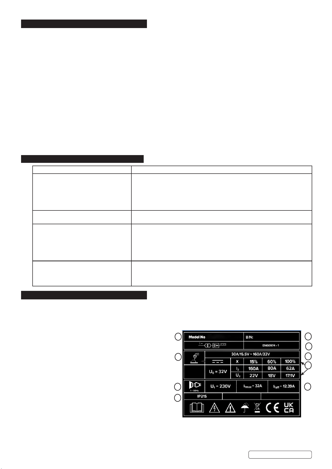
8. RATING PLATE
On the front panel of the welder is the ratings plate, giving the following data:
1 - The BS/EU standard relating to the safety and construction of arc
welding and associated equipment.
2 - Single phase transformer.
3 - Symbol indicates welding with a continuous flow of welding wire.
4 - Symbol for Single-phase AC supply.
5 - Rating of internal protection provided by casing.
6 - Output U
0
Rated minimum and maximum no load voltage.
I
2
, U
2
Current and corresponding voltage.
X Welding ratio based on a 10 minute cycle.
20% indicates 2 minutes welding and 8 minutes rest,
100% would indicate continuous welding.
7 - Mains Supply
U
1
Rated supply voltage and frequency.
I
1
max Maximum current.
I
1
eff Maximum effective current.
8 - Welding current range.
9 - Serial Number. Specifically identifies each welder.
FAULT CAUSE
The wire does not move or wire entangles. Feed rollers, wire conduit or contact tips are defective.
Check that the feed rollers are not too tight or too loose.
Check that the feed roller isn’t worn.
Check that the wire liner is not blocked.
Check that there are no splatters on the conduit tip and that the hole is not cramped or
worn loose.
Main switch indicator light does not switch on. No supply voltage.
Check fuses.
Machine welds badly. Welding outcome is inuenced by following factors.
Check the trimming settings of the welding power control and arc length.
Check that the earthing clamp is xed properly also the xing point is clean and the
connections are undamaged.
Check the ow of shielding gas from the tip of the welding gun.
Supply voltage is uneven or too high or too low.
Overheating indicator light comes on. The machine has overheated.
Check that the cooling air can ow without obstructions.
Machine volume - capacity has been exceeded; wait for indicator light to switch o.
The supply voltage is to high or low.
2
4
5
For Illustration Only
3
9
7
1
8
6
Original Language Version
© Jack Sealey Limited
MIG200i Issue 2 10/01/25

Original Language Version
© Jack Sealey Limited
Sealey Group, Kempson Way, Suffolk Business Park, Bury St Edmunds, Suffolk. IP32 7AR
01284 757500 sales@sealey.co.uk www.sealey.co.uk
Note: It is our policy to continually improve products and as such we reserve the right to alter data, specifications and component parts without prior
notice.
Important: No Liability is accepted for incorrect use of this product.
Warranty: Guarantee is 12 months from purchase date, proof of which is required for any claim.
ENVIRONMENT PROTECTION
Recycle unwanted materials instead of disposing of them as waste. All tools, accessories and packaging should be sorted,
taken to a recycling centre and disposed of in a manner which is compatible with the environment. When the product
becomes completely unserviceable and requires disposal, drain any fluids (if applicable) into approved containers and
dispose of the product and fluids according to local regulations.
WEEE REGULATIONS
Dispose of this product at the end of its working life in compliance with the EU Directive on Waste Electrical and Electronic Equipment
(WEEE). When the product is no longer required, it must be disposed of in an environmentally protective way. Contact your local solid
waste authority for recycling information.
REGISTER YOUR
PURCHASE HERE
MIG200i Issue 2 10/01/25