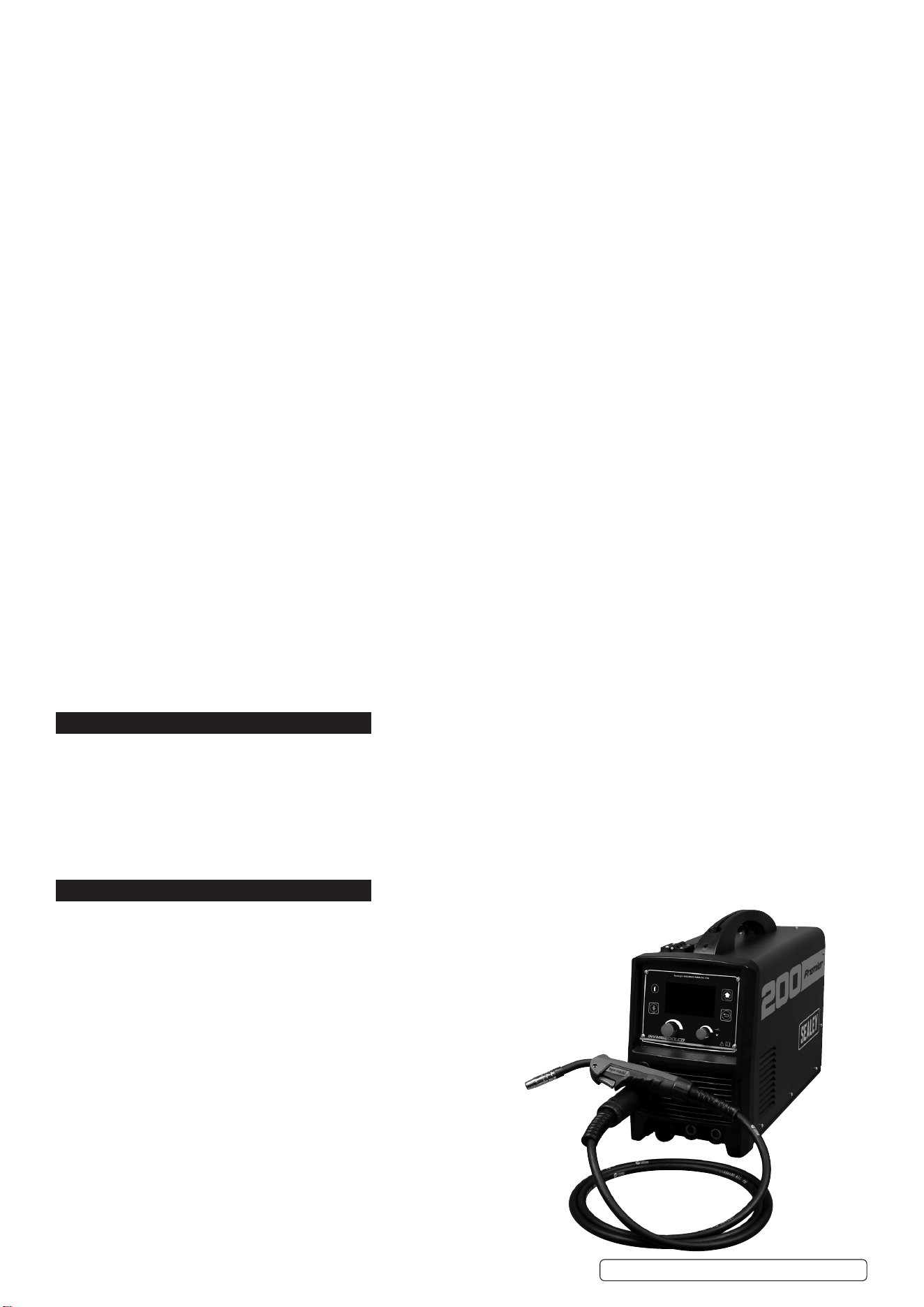
200A MIG, TIG & MMA INVERTER WELDER WITH
LCD SCREEN
MODEL NO: INVMIG200LCD.V2
Thank you for purchasing a Sealey product. Manufactured to a high standard, this product will, if used according to these instructions,
and properly maintained, give you years of trouble free performance.
IMPORTANT: PLEASE READ THESE INSTRUCTIONS CAREFULLY. NOTE THE SAFE OPERATIONAL REQUIREMENTS, WARNINGS & CAUTIONS. USE
THE PRODUCT CORRECTLY AND WITH CARE FOR THE PURPOSE FOR WHICH IT IS INTENDED. FAILURE TO DO SO MAY CAUSE DAMAGE AND/OR
PERSONAL INJURY AND WILL INVALIDATE THE WARRANTY. KEEP THESE INSTRUCTIONS SAFE FOR FUTURE USE.
1. SAFETY
1.1. ELECTRICAL SAFETY
WARNING! It is the owner’s responsibility to read, understand and comply with the following:
You must check all electrical equipment and appliances to ensure that they are safe before use. You must inspect power supply leads,
plugs and all electrical connections for wear and damage. You must ensure the risk of electric shock is minimised by the installation of
appropriate safety devices. An RCCB (Residual Current Circuit Breaker) should be incorporated in the main distribution board. We also
recommend that an RCD (Residual Current Device) is used with all electrical products. It is particularly important to use an RCD with
portable products that are plugged into an electrical supply not protected by an RCCB. If in doubt consult a qualified electrician.
You must also read and understand the following instructions concerning electrical safety.
1.1.1. The Electricity At Work Act 1989 requires all portable electrical appliances, if used on business premises, to be tested by a qualied
electrician, using a Portable Appliance Tester (PAT), at least once a year.
1.1.2. The Health & Safety at Work Act 1974 makes owners of electrical appliances responsible for the safe condition of the appliance
and the safety of the appliance operator. If in any doubt about electrical safety, contact a qualified electrician.
Ensure the insulation on all cables and the product itself is safe before connecting to the mains power supply.
See 1.1.1. & 1.1.2. above and use a Portable Appliance Tester (PAT).
Ensure that cables are always protected against short circuit and overload.
Regularly inspect power supply, leads, plugs for wear and damage and all electrical connections
to ensure that none is loose.
Important: Ensure the voltage marked on the product is the same as the electrical power supply
to be used and check that supply is correctly fused, see fuse rating at right.
8 DO NOT pull or carry the powered appliance by its power supply lead.
8 DO NOT pull power plugs from sockets by the power cable.
8 DO NOT use worn or damaged leads, plugs or connections. Immediately replace or have
repaired by a qualified electrician.
This product comes without a plug. You must contact a qualified electrician to ensure an
adequate supply is available.
If fitting such a plug -
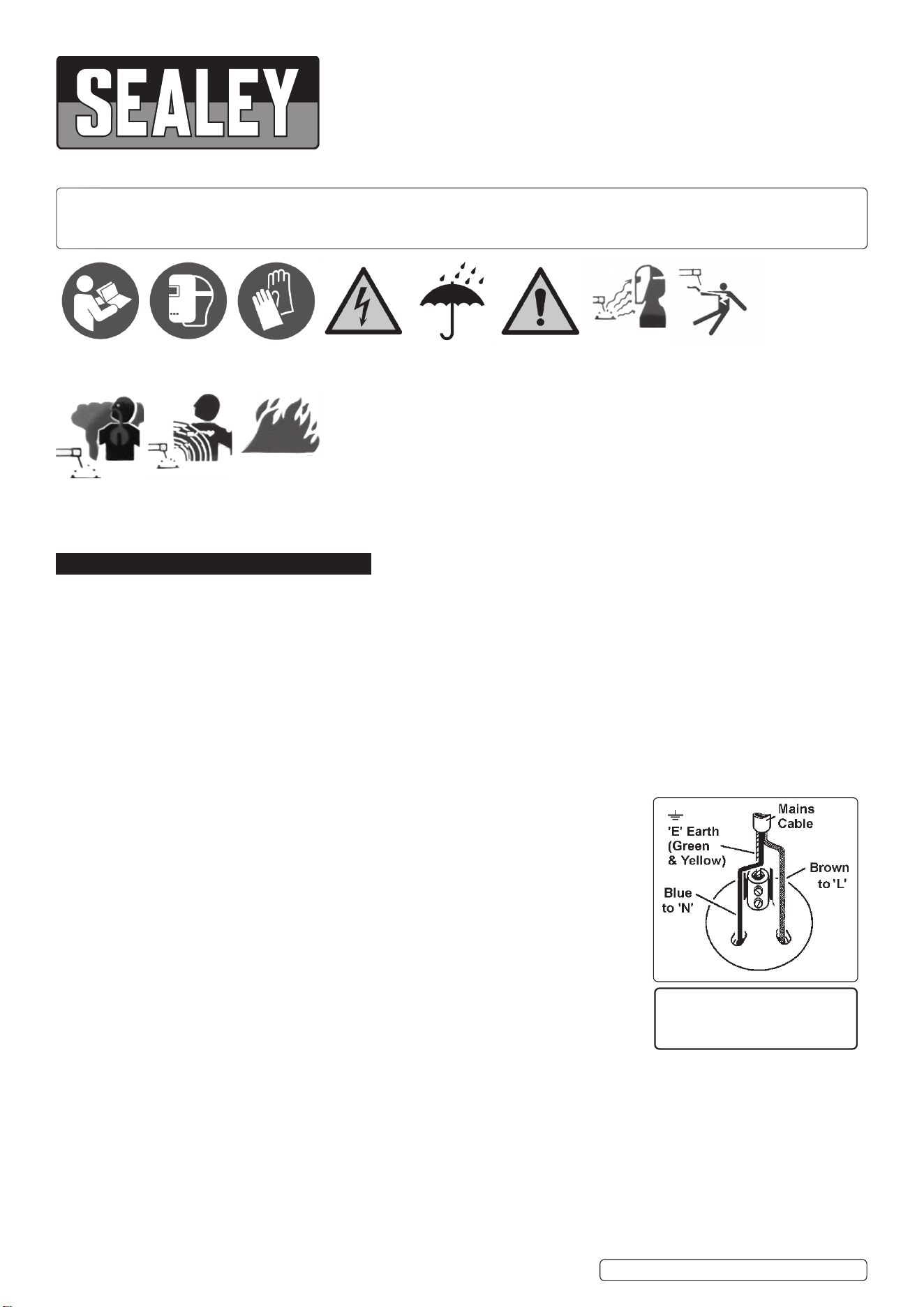
Ensure that the unit is correctly wired and earthed, as follows:
a) Connect the GREEN/YELLOW earth wire to the earth terminal ‘E’.
b) Connect the BROWN live wire to live terminal ‘L’.
c) Connect the BLUE neutral wire to the neutral terminal ‘N’.
d) After wiring, check there are no bare wires, that all wires have been correctly connected, that the cable outer
insulation is clamped by the cable grip and that the grip is tight.
1.1.3. Cable extension reels. When a cable extension reel is used it should be fully unwound before connection. A cable reel with an RCD
fitted is recommended since any product which is plugged into the cable reel will be protected. The section of the cores of the cable is
important. 2.5mm² section is a minimum, but to be absolutely sure that the capacity of the cable reel is suitable for this product and
for others that may be used in the other output sockets, we recommend the use of 2.5mm² section cable.
WARNING! Be very cautious if using a generator to power the welder. The generator must be self-regulating and stable with regard
to voltage, wave form and frequency. The output must be greater than the power consumption of the welder. If any of these requirements
is not met the electronics within the welder may be affected.
NOTE: The use of an unregulated generator may be dangerous and will invalidate the warranty on the welder.
THIS PRODUCT REQUIRES A
MINIMUM 16 AMP
SUPPLY
Original Language Version
© Jack Sealey Limited
Refer to
instruction
manual
Wear a
welding
mask
Wear protective
gloves
Warning!
electrical
shock hazard
Warning!
keep away
from rain
Caution
required
Arc rays can
burn eyes and
injure skin
Breathing
welding fumes
can be
hazardous to
your health
Electric shock
from welding
electrodes can
kill
Electromagnetic
fields can cause
pacemaker
malfunction
Welding sparks
can cause
explosions
or fire
INVMIG200LCD.V2 Issue:2 (1) 18/01/23

WARNING! The welder may produce voltage surges in the mains supply which can damage other sensitive equipment
(e.g. computers). To prevent this happening, it is recommended that the welder is connected to a power supply that does not
feed any sensitive equipment.
To achieve maximum output INVMIG200LCD will require a 32A fused supply. We recommend you discuss the installation of
an industrial round pin plug and socket with a competent electrician.
1.2. GENERAL SAFETY
9 Read and understand all instructions. Failure to follow all instructions listed below may result in serious injury.
CAUTION: Do not allow persons to operate or assemble this welder until they have read this manual and have developed a thorough
understanding of how the welder works.
WARNING: The warnings, cautions, and instructions discussed in this instruction manual cannot cover all possible conditions or
situations that could occur. It must be understood by the operator that common sense and caution are factors which cannot be built
into this product, but must be supplied by the operator.
9 SAVE THESE INSTRUCTIONS
1.2.1. WELDING ENVIRONMENT
9 Keep the environment you will be welding in free from ammable materials.
9 Always keep a re extinguisher accessible to your welding environment.
9 Always have a qualied person install and operate this equipment.
9 Make sure the area is clean, dry and ventilated. Do not operate the welder in humid, wet or poorly ventilated areas.
9 Always have your welder maintained by a qualied technician in accordance with local, state and national codes.
9 Always be aware of your work environment. Be sure to keep other people, especially children, away from you while welding.
9 Keep harmful arc rays shielded from the view of others.
9 Mount the welder on a secure bench or cart that will keep the welder secure and prevent it from tipping over or falling.
1.2.2. WELDER CONDITION
9 Check ground cable, power cord and welding cable to be sure the insulation is not damaged. Always replace or repair damaged
components before using the welder.
9 Check all components to ensure they are clean and in good operating condition before use.
1.2.3. SAFE USE OF YOUR WELDER
8 DO NOT operate the welder if the output cable, electrode, torch, wire or wire feed system is wet. DO NOT immerse them in water.
These components and the welder must be completely dry before attempting to use them.
9 Follow the instructions in this manual.
9 Keep welder in the o position when not in use.
9 Connect ground lead as close to the area being welded as possible to ensure a good ground.
8 DO NOT allow any body part to come in contact with the welding wire if you are in contact with the material being welded, ground or
electrode from another welder.
8 DO NOT weld if you are in an awkward position. Always have a secure stance while welding to prevent accidents. Wear a safety
harness if working above ground.
8 DO NOT drape cables over or around your body.
9 Wear a full coverage helmet with appropriate shade and safety glasses while welding.
9 Wear proper gloves and protective clothing to prevent your skin from being exposed to hot metals, UV and IR rays.
8 DO NOT overuse or overheat your welder. Allow proper cooling time between duty cycles.
9 Keep hands and ngers away from moving parts and stay away from the drive rolls.
8 DO NOT point torch at any body part of yourself or anyone else.
9 Always use this welder in the rated duty cycle to prevent excessive heat and failure.
1.2.4. SPECIFIC AREAS OF DANGER, CAUTION OR WARNING
1.2.4.1. ELECTRICAL SHOCK
9 Electric arc welders can produce a shock that can cause injury or death. Touching electrically live parts can cause fatal shocks and
severe burns. While welding, all metal components connected to the wire are electrically hot. Poor ground connections are a hazard,
so secure the ground lead before welding.
9 Wear dry protective apparel: coat, shirt, gloves and insulated footwear.
9 Insulate yourself from the work piece. Avoid contacting the work piece or ground.
8 DO NOT attempt to repair or maintain the welder while the power is on.
9 Inspect all cables and cords for any exposed wire and replace immediately if found. Use only recommended replacement cables and
cords.
9 Always attach ground clamp to the work piece or work table as close to the weld area as possible.
8 DO NOT touch the welding wire and the ground or grounded work piece at the same time.
8 DO NOT use a welder to thaw frozen pipes.
1.2.4.2. FUMES AND GASES
9 Fumes emitted from the welding process displace clean air and can result in injury or death.
8 DO NOT breathe in fumes emitted by the welding process. Make sure your breathing air is clean and safe.
9 Work only in a well-ventilated area or use a ventilation device to remove welding fumes from the environment where you will be
working.
8 DO NOT weld on coated materials (galvanized, cadmium plated or containing zinc, mercury or barium). They will emit harmful fumes
that are dangerous to breathe. If necessary use a ventilator, respirator with air supply or remove the coating from the material in the
weld area.
9 The fumes emitted from some metals when heated are extremely toxic. Refer to the material safety data sheet for the manufacturer’s
instructions.
8 DO NOT weld near materials that will emit toxic fumes when heated. Vapours from cleaners, sprays and degreasers can be highly
toxic when heated.
1.2.4.3. UV AND IR ARC RAYS
9 The welding arc produces ultraviolet (UV) and infrared (IR) rays that can cause injury to your eyes and skin. DO NOT look at the
welding arc without proper eye protection.
9 Always use a helmet that covers your full face from the neck to top of head and to the back of each ear.
9 Use a lens that meets ANSI standards and safety glasses.
Original Language Version
© Jack Sealey Limited
INVMIG200LCD.V2 Issue:2 (1) 18/01/23
9 Cover all bare skin areas exposed to the arc with protective clothing and shoes.
Flame-retardant cloth or leather shirts, coats, pants or coveralls are available for protection.
9 Use screens or other barriers to protect other people from the arc rays emitted from your welding.
9 Warn people in your welding area when you are going to strike an arc so they can protect themselves.
1.2.4.4. FIRE HAZARDS
8 DO NOT weld on containers or pipes that contain or have had ammable, gaseous or liquid combustibles in them. Welding creates
sparks and heat that can ignite ammable and explosive materials.
8 DO NOT operate any electric arc welder in areas where ammable or explosive materials are present.
9 Remove all ammable materials within 10m of the welding arc. If removal is not possible, tightly cover them with reproof covers.
9 Take precautions to ensure that ying sparks do not cause res or explosions in hidden areas, cracks or areas you cannot see.
9 Keep a re extinguisher close in the case of re.
9 Wear garments that are oil-free with no pockets or cus that will collect sparks.
8 DO NOT have on your person any items that are combustible, such as lighters or matches.
9 Keep work lead connected as close to the weld area as possible to prevent any unknown, unintended paths of electrical current from
causing electrical shock and re hazards.
9 To prevent any unintended arcs, cut wire back to ¼” stick out after welding.
1.2.4.5. HOT MATERIALS
9 Welded materials are hot and can cause severe burns if handled improperly. DO NOT touch welded materials with bare hands.
8 DO NOT touch MIG gun nozzle after welding until it has had time to cool down.
1.2.4.6. SPARKS/FLYING DEBRIS
9 Welding creates hot sparks that can cause injury. Chipping slag o welds creates ying debris.
9 Wear protective apparel at all times: Wear approved safety glasses or shield, welder’s hat and ear plugs to keep sparks out of ears
and hair.
1.2.4.7. ELECTROMAGNETIC FIELD
9 Electromagnetic elds can interfere with various electrical and electronic devices such as pacemakers. Consult your doctor before
using any electric arc welder or cutting device
9 Keep people with pacemakers away from your welding area when welding.
8 DO NOT wrap cable around your body while welding.
9 Wrap MIG gun and ground cable together whenever possible.
9 Keep MIG gun and ground cables on the same side of your body.
1.2.4.8. GAS CYLINDER
9 High pressure cylinders can explode if damaged, treat them carefully.
9 Never expose cylinders to high heat, sparks, open ames, mechanical shocks or arcs.
8 DO NOT touch cylinder with MIG gun.
8 DO NOT weld on the cylinder
9 Always secure cylinder upright to a cart or stationary object.
9 Keep cylinders away from welding or electrical circuits.
9 Use the proper regulators, gas hose and ttings for the specic application.
8 DO NOT look into the valve when opening it.
9 Use protective cylinder cap whenever possible
2. INTRODUCTION
3 in 1 welder - uses state-of-the-art inverter technology to achieve MIG/TIG/MMA (Arc). Inverter technology oers many advantages over
traditional transformer type welders, giving greater duty cycles and more power factor eciency. Fan Cooled DC power supply for MIG and TIG,
suitable to weld steel, stainless steel, copper, nickel, titanium, and their alloys. Also suitable for MMA (Arc) welding - a variety of rods including
rutile, basic and stainless from Ø1.6 to ø4mm. Fully functional - LCD front panel with easy to follow set-up. First, select type of welding, you
will be advised the gas mixture and polarity recommended. Input electrode or wire thickness, completing the set-up with the material thickness,
you are then ready to start welding. Up to four set-ups can be saved on the machine for fast loading. Switchable between MIG, TIG* or MMA*
welding modes (*optional torches required). Supplied with 3m MIG torch, 3m 16mm² earth cable, both with 35-70 quick connectors, 4m gas
hose and regulator.
3. SPECIFICATION
Model No: ...............................................INVMIG200LCD.V2
MIG: ........................................... 20% @ 200A, 100% @ 89A
TIG: ............................................ 20% @ 180A, 100% @ 80A
MMA (Arc): .................................20% @ 180A, 100% @ 80A
Wire Capacity:..................................................................5kg
Electrode Capacity: ................................................1.6 - 4mm
Absorbed Power: .........................................................8.6kW
Supply: .......................................................................230V **
Insulation: .................................................................... IP21S
Protection: ............................................................................F
MIG Torch: ...........................Euro Non-Live BINZEL® MB15*
MMA Accessory Kit (Optional): ...................................MMA01
TIG Accessory Kit (Optional): ....................................TIG10S
* included as standard
** To achieve maximum power a 32A supply may be required.
Original Language Version
© Jack Sealey Limited
INVMIG200LCD.V2 Issue:2 (1) 18/01/23
4. FEATURES
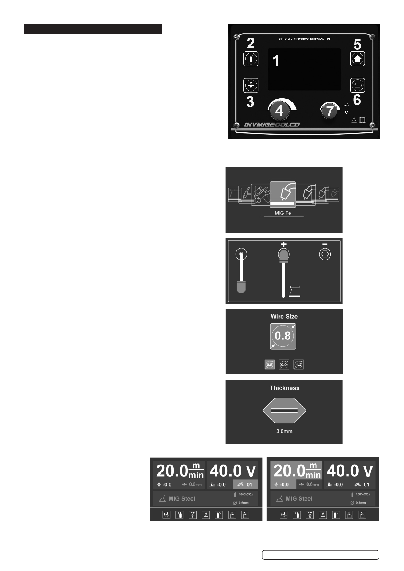
1. LCD: Shows all process from function selection to welding.
2. Gas-check button: press the button and the gas supply system works.
3. Wire-check button: press the button and the wire supply system works.
4. Multi-function adjusting knob: For function selection
Allows user to adjust the current and wire feeding speed accurately.
5. Home Key: Keep pressing home key, return to home page.
6. Return: Return to the previous step.
7. Auxiliary knob: Allows user to adjust the voltage accurately.
4.1. INTERFACE DESCRIPTION
4.1.1. Multi-function selection:
Total 9 functions, 8 welding functions and 1 setting.
Turn multi-function knob for selection, press to conrm.
4.1.2. Output setup:
Shows output connection under dierent welding modes,
press multi-function knob to conrm.
4.1.3. Electrode/ Wire diameter selection:
Turn multi-function knob to select dierent electrode/wire
diameter, press to conrm.
4.1.4. Material thickness:
Adjusting multi-function knob to select dierent material thickness,
press to conrm.
4.1.5. Welding display:
Shows all selected parameters.
A. With MIG welding selected,
user can set wire
feeding speed and voltage.
Turn Multi-function knob to set
electro-inductance,
Press the knob to progress
basic parameter setting.
Note:
i: Basic parameter settings are: gas pre ow, slow wire feeding, gas post ow, operating, load and save function.
Original Language Version
© Jack Sealey Limited
INVMIG200LCD.V2 Issue:2 (1) 18/01/23
There is also spool gun function under Al welding.
Note ii: Green highlighted parameters are the recommended ones.
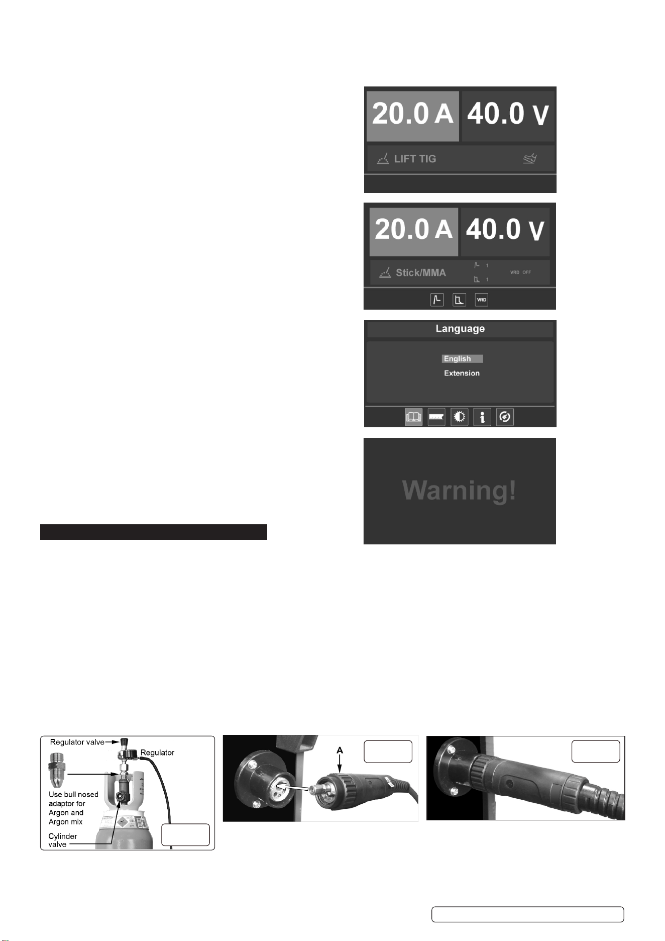
B. TIG welding, user can set current parameter.
C. Stick welding, user can set current, arc force parameter
and hot start.
4.1.6. Select Interface use to select:
language, units, light settings, information and recover settings.
4.1.7. Alarm interface: shows the machine is overloaded and the
internal temperature is too high. Weld output will turn o
automatically but the fan will still be working.
When the internal temperature is decreased, the alarm interface
will turn o and the machine will be ready to weld.
5. PREPARATION
5.1. GAS SUPPLY
5.1.1. ATTACHING THE REGULATOR. (fig.3) Whichever gas you are using it is advisable to ‘crack’ the cylinder valve before attaching the
regulator. This means opening and closing the valve very quickly in order to blow away any dust and dirt that may have accumulated in
the gas outlet. Stand to one side whilst doing this.
5.1.2. CO
²
GAS. Ensure that the threads on the gas bottle are undamaged and free of oil and grease before attaching the regulator. (Oil or grease
in the presence of high pressure gases can be explosive.) Ensure that the regulator has an undamaged gasket fitted. The regulator will
screw directly to the threads on the gas bottle. Tighten with a wrench.
5.1.3. ARGON GAS OR ARGON MIXTURES. Cylinders containing argon gas and argon mixtures have a female thread and will require the use of
a Bull Nose Adaptor to attach the regulator to the cylinder as indicated in fig.3. Ensure that the threads on the gas bottle are undamaged and
free of oil and grease before attaching the regulator. (Oil or grease in the presence of high pressure gases can be explosive.) Fit the Bull
Nose Adaptor to the cylinder first and tighten with a wrench.
5.1.4. Slide a hose clip over each end of the gas hose supplied. Push one end of the hose onto the regulator outlet and the other end over
the gas inlet spigot on the back of the welder. Tighten the clips to ensure a good seal.
5.1.5. Close the regulator valve by turning it anticlockwise before opening the cylinder valve. Stand to one side when opening.
5.1.6. Set the regulator flow rate to 5-8 litres/min depending on the material to be welded, and whether there are draughts which are strong
enough to disturb the gas flow.
5.2. CONNECTING THE TORCH CABLE TO THE WELDER. Align the pins on the Euro connector with the socket on the welder front
panel as shown in g.4. Push the connector into the socket and rotate the locking ring (A) clockwise so that it draws the plug into the
socket as shown in g.5.
g.3
g.4
g.5
Original Language Version
© Jack Sealey Limited
INVMIG200LCD.V2 Issue:2 (1) 18/01/23
Note: damage to torches and cables is not covered by warranty.
5.3. FITTING A REEL OF WIRE (FIG.6). INVMIG200LCD will accept up to a 5kg reel of wire. Ensure that the wire diameter used is
matched by the correct groove size in the drive wheel and the correct tip size on the torch as well as the correct torch liner.
Failure to do this could cause the wire to slip and/or bind.
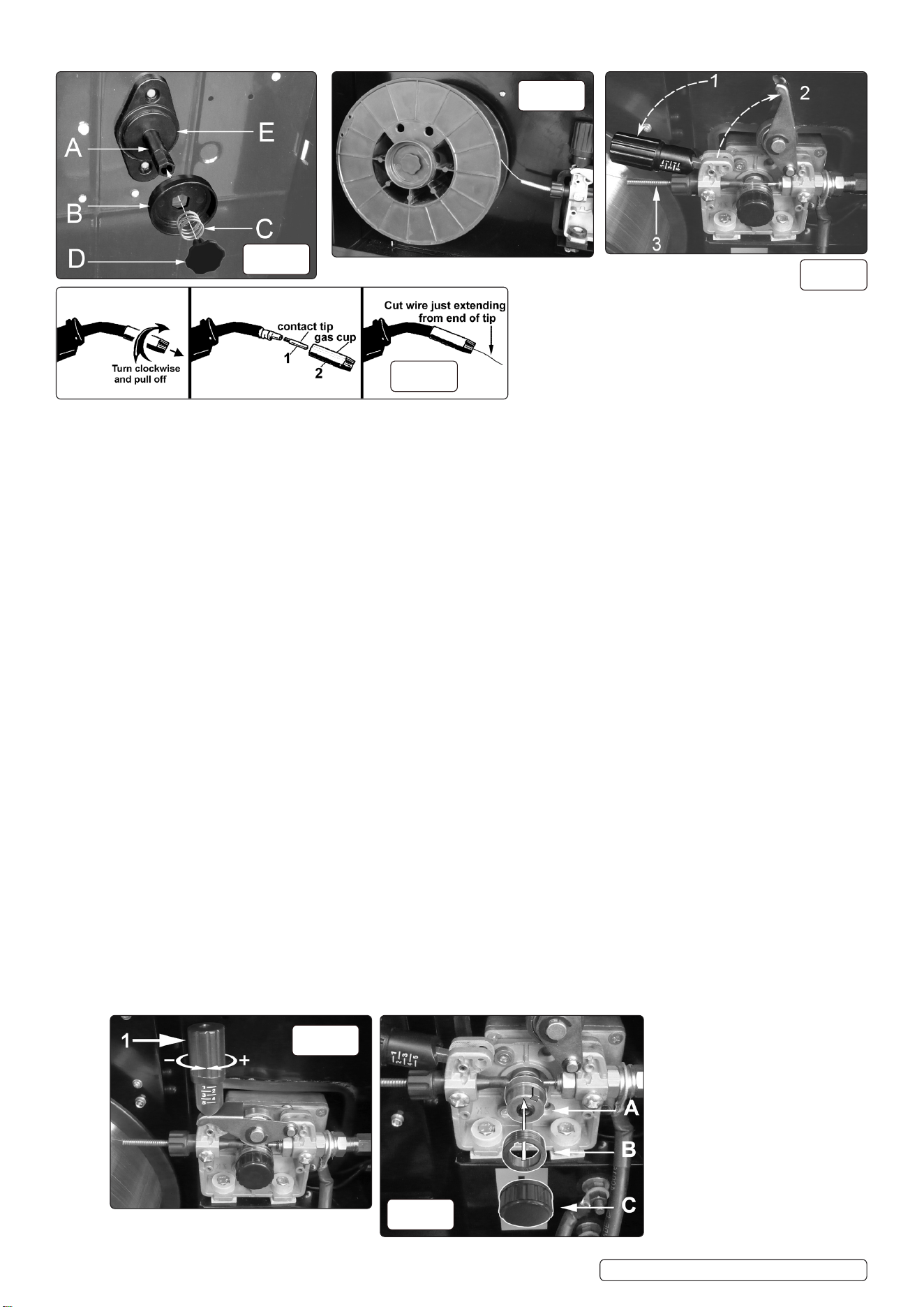
5.3.1. Remove the retaining control (D) from the end of the spindle (A) by turning the control 90° anticlockwise and pulling it outwards. Remove the
spring (C) and the retaining disc (B) from the end of the spindle also. Slide the reel of wire over the spindle and hold it against the back plate
so that the hole in the reel rests on the flange (E). Ensure that the wire is coming off the top of the reel in the direction of the wire drive
unit as shown in fig.7.
5.3.2. Retain hand pressure on the reel to keep it on the flange and slide the retaining disc (B) over the end of the spindle and into the hole in
the reel. Note that the disc (B) has a hexagonal hole in it which fits onto the hexagonal portion of the spindle. Keep the disc under hand
pressure to retain the reel. Place the spring (C) over the spigot of the retaining control (D). Match the indented end of the spigot to the
hole in the end of the spindle. Push the control spigot into the end of the spindle, against spring pressure and turn it through 90° to lock it
in place.
5.4. FEEDING WIRE THROUGH TO TORCH. Open the wire feed mechanism by pushing the locking/wire tension control (fig.8.1) down to the
left allowing the pressure roller carrier (fig.8.2) to spring up revealing the feed roller.
Ensure that the required feed groove (0.6 or 0.8) is in line with the wire path. See Section 5.6. on how to reverse or change the roller.
5.4.1. Release the wire from the reel and cut off any bent portion ensuring that there are no burrs left on the end of the wire. Keep the wire under
tension at all times to prevent it uncoiling.
5.4.2. Straighten about 40-50mm of wire and push it gently through the flexible metal sheathed cable (fig.8.3) and through the 0.6mm or 0.8mm
feed roller groove and on into the torch cable liner.
5.4.3. Push down the pressure roller carrier onto the wire feed roller and hold it down. Lift up the locking/wire tension control so that it enters the
slot in the pressure roller carrier and snaps into the indent in its top surface (fig.8). Rotate the tension control to a medium setting i.e.
between 2 and 3.
5.4.4. Remove gas cup (fig.9.2) and contact tip (fig.9.1) from end of torch as follows:
a) Take torch in left hand with the torch tip facing to the right.
b) Grasp gas cup firmly in your right hand.
c) Turn gas cup clockwise only and pull it off end of torch tip.
WARNING!WARNING! DO NOTDO NOT turn gas cup anti-clockwise, as this will damage the internal spring. turn gas cup anti-clockwise, as this will damage the internal spring.
d) Unscrew copper contact tip (right hand thread) to remove. d) Unscrew copper contact tip (right hand thread) to remove.
5.4.5. Check welder is switched off and that the earth clamp is away from the torch tip.
5.4.6. Connect the welder to the mains power supply and select the MIG setting by means of the multi-function control.
5.4.7. 5.4.7. Set the voltage control (fig.2.3) to minimum .
5.4.8. Set the wire speed control (fig.2.2.) to minimum. Keep the torch cable as straight as possible and press the torch switch. The wire will
feed through the torch.
a) Take torch in left hand, slide the contact tip over the wire and screw back into place.
b) Grasp gas cup in right hand, push onto torch head and turn clockwise only. Do not turn gas cup anti-clockwise, as this will damage the
internal spring.
c) Cut wire so that it is just protruding from the cup. c) Cut wire so that it is just protruding from the cup.
g.6
g.7
g.8
g.9
g.10
g.11
Original Language Version
© Jack Sealey Limited
INVMIG200LCD.V2 Issue:2 (1) 18/01/23
5.5. 5.5. SETTING WIRE TENSION. Adjust the wire tension by rotating the wire tension control. Turn clockwise to increase the tension and
anticlockwise to decrease the tension. See fig 10.1.See fig 10.1.
IMPORTANT:IMPORTANT: Too little or too much tension will cause wire feed problems and result in poor welding. Too little or too much tension will cause wire feed problems and result in poor welding.
5.5.1. 5.5.1. Tension between rollers is checked by slowing down the wire between gloved fingers. If top feed roller skids the tension is correct. Use as If top feed roller skids the tension is correct. Use as
low a tension as possible; too high a tension could crush the wire and result in a blown fuse. low a tension as possible; too high a tension could crush the wire and result in a blown fuse.
5.6. 5.6. TURNING/CHANGING THE DRIVE ROLLER TURNING/CHANGING THE DRIVE ROLLER.. (See figs. 8 and 11.) (See figs. 8 and 11.) Ensure that the wire diameter (0.6/0.8mm) used is matched by the
correct groove size in the drive wheel and the correct tip size on the torch as well as the correct torch liner. Failure to do so could cause
the wire to slip and/or bind.
5.6.1. Referring to fig.8, open the wire feed mechanism by pushing the locking/wire tension control (1) down to the left allowing the pressure
roller carrier (2) to spring up revealing the feed roller.
5.6.2. 5.6.2. Referring to figure 11, move control (C) and put to one side. Referring to figure 11, move control (C) and put to one side.
5.6.3. 5.6.3. The roller carrier (A) is keyed to the main drive shaft and the drive roller (B) is keyed to the carrier, see below. Place a finger onto the end The roller carrier (A) is keyed to the main drive shaft and the drive roller (B) is keyed to the carrier, see below. Place a finger onto the end
of the drive shaft to prevent the carrier moving and slide the drive roller off the carrier with your other hand. of the drive shaft to prevent the carrier moving and slide the drive roller off the carrier with your other hand.
5.6.4. The size of each wire feed groove is printed on the edge of the roller on the same side as the groove.
5.6.5. 5.6.5. Turn the roller over to use the other groove or use a roller with different sized grooves as required. The groove to be used should be Turn the roller over to use the other groove or use a roller with different sized grooves as required. The groove to be used should be
positioned furthest away from you to be in line with the drive path. positioned furthest away from you to be in line with the drive path.
5.6.6. 5.6.6. Check that the key in the carrier (A) is seated properly in its slot. Ensure that the slot on the inside face of the drive roller (B) is aligned Check that the key in the carrier (A) is seated properly in its slot. Ensure that the slot on the inside face of the drive roller (B) is aligned
with the key and slide the roller back onto the carrier. with the key and slide the roller back onto the carrier.
5.6.7. 5.6.7. Screw the black roller retaining control (C) back on to the end of the drive shaft and tighten. Screw the black roller retaining control (C) back on to the end of the drive shaft and tighten.
5.7. CONVERTING TO GASLESS WELDING.
5.7.1. Toweldwithoutgas(usinguxcoredwire)thepowerinputleadmustbeconnected to
the negative (-) terminal and the earthing cable to the positive (+) terminal.
Follow the directions given in the Output Setup interface section 4.1.2. for each type of
welding.
WARNING! Ensure that the machine is switched o and unplugged from the mains supply
before carrying out this task.
5.7.2. Disconnect the gas safely.
5.7.3. Fit a 1.0mm tip to the torch.
5.7.4. Mount the ux cored wire reel and feed it through to the torch.
5.7.5. Use the multi-function selection control to navigate to the ux cored wire setting. Press to conrm.
6. MIG/MAG WELDING
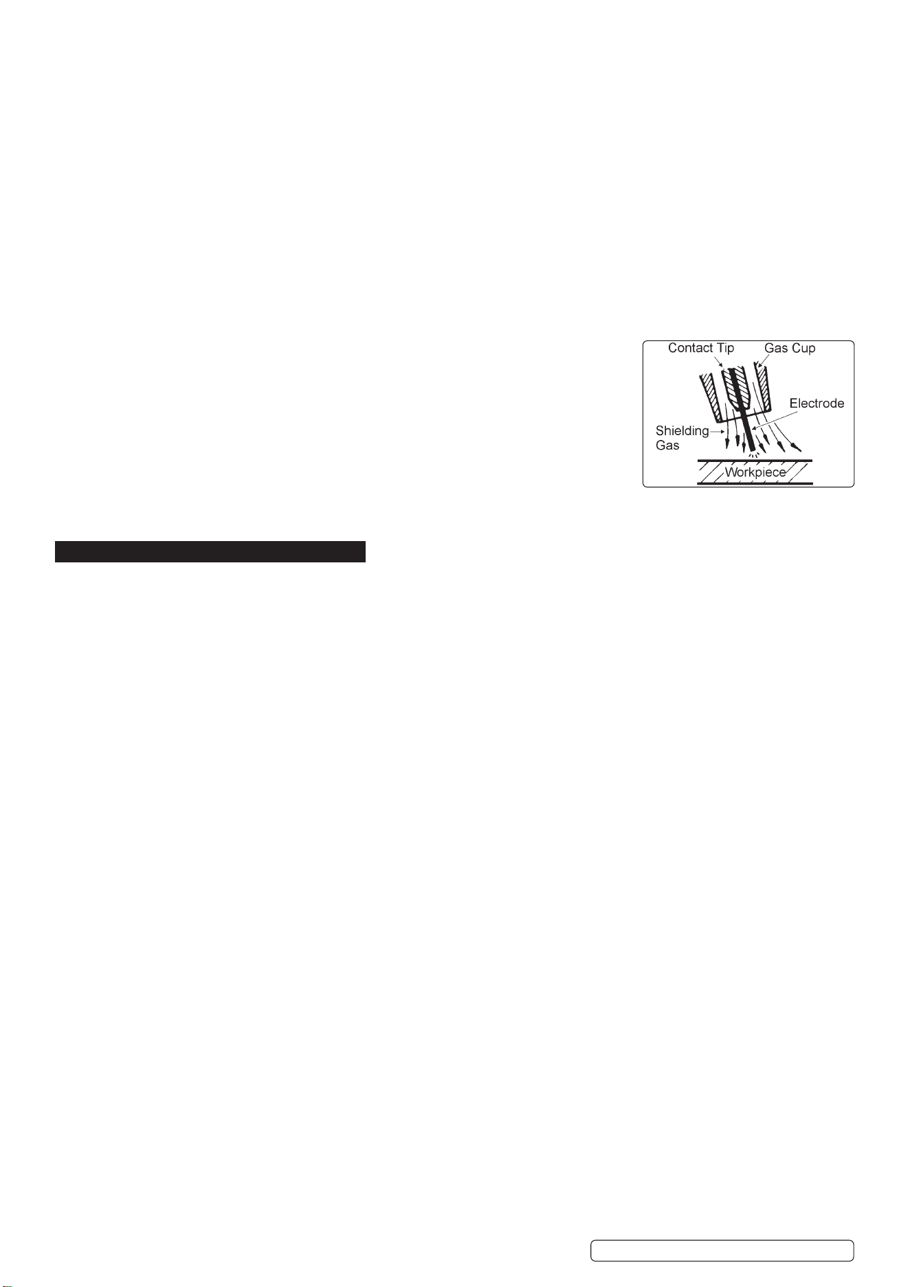
6.1. A spool of welding wire is positioned on the welder’s spool holder and automatically fed through an insulated liner in the torch to the
tip. The torch assembly consists of a switch, liner, gas hose, and control cable. The switch activates the wire feed roller and the gas flow.
6.2. Conversely, releasing the switch stops the wire feed and gas flow. The weld current is transferred to the electrode (the wire) from the
contact tip at the end of the torch. A gas cup fits over the contact tip to direct the gas flow towards the weld ensuring that the arc welding
process is shielded from oxidising air contaminates. The shielding gas also assists heating of the weld materials. (The welder can also
be used in gasless mode using flux cored wire). The torch is connected to the positive side of a DC rectifier, and the negative clamp is
attached to the workpiece.
IMPORTANT: Should you have no welding experience, we recommend you seek training from an expert source to ensure your
personal health & safety. Good Mig welding may be achieved only with continued, supervised practice.
6.3. PREPARATION FOR WELDING
IMPORTANT: BEFORE YOU COMMENCE, MAKE SURE THE MACHINE IS DISCONNECTED FROM THE ELECTRIC SUPPLY. IF
WELDING A MOTOR VEHICLE, DISCONNECT THE BATTERY OR FIT AN ELECTRONIC CIRCUIT PROTECTOR. WE
RECOMMEND STRONGLY THE USE OF SEALEY “PROSAF/12V OR 24V” IN ORDER TO PROTECT SOPHISTICATED
ELECTRONICS. ENSURE THAT YOU HAVE READ & UNDERSTOOD THE ELECTRICAL SAFETY INSTRUCTIONS IN SECTION 1.
6.3.1. Clean the area to be welded: remove any oxidisation, grease and paint, if necessary, grind the area to a bright finish.
6.3.2. Mode: Select required mode via the multi-function adjustment control.
A second press will show the required earth and torch connections and the recommended gas ratio.
6.3.3. Subsequent presses will allow the electrode diameter and material thickness to be entered, using the multi-function control.
6.3.4. Having set the material thickness, a further press of the multi-function control will bring up the default welding settings.
The voltage and wire speed may be adjusted by use of the right and left adjustment controls.
NOTE: The recommended settings are shown by the green sector of the display. Inappropriate settings are denoted by the voltage
and wire feed numerals turning red.
6.4. ALUMINIUM WELDING
6.4.1. To weld aluminium use:
● Argon gas,
● 0.8mm Contact Tip (MIG927),
● 0.8mm Aluminium Wire, (MIG/2KAL08).
A clean torch liner is essential, as any contamination of the aluminium wire will produce a poor weld.
6.4.2. Using the multi-function selection control, enter the aluminium welding pages, and follow the on-screen instructions as in 5.1.
6.5. ARC WELDING
NOTE: Arc welding cables are not supplied with this machine. Sealey part no: MMA01 is suitable.
WARNING! Ensure that the inverter is not plugged into the mains power supply before connecting or disconnecting cables.
For electrical installation, see Safety Instructions (Section 1).
6.5.1. Using the multi-function selection control, enter the stick welder pages, and follow the on-screen instructions as in 5.1.
6.5.2. Observe the location of the torch and earth cables and connect accordingly.
6.5.3. Enter the electrode type (60xx or 70xx), diameter and material thickness when prompted
6.5.4. The welding current and gas post ow may be adjusted from the default settings in this mode.
Original Language Version
© Jack Sealey Limited
INVMIG200LCD.V2 Issue:2 (1) 18/01/23
7. TIG WELDING
WARNING! Ensure that the inverter is not plugged into the mains power supply before connecting or disconnecting cables.
For electrical installation, see Safety Instructions (Section 1).
7.1. Using the multi-function selection control, enter the TIG welder pages, and follow the on-screen instructions.
7.1.1. Observe the location of the torch and earth cables and connect accordingly.
7.2. Enter the tungsten electrode diameter and material thickness when prompted.
7.3. The welding current may be adjusted in this mode.
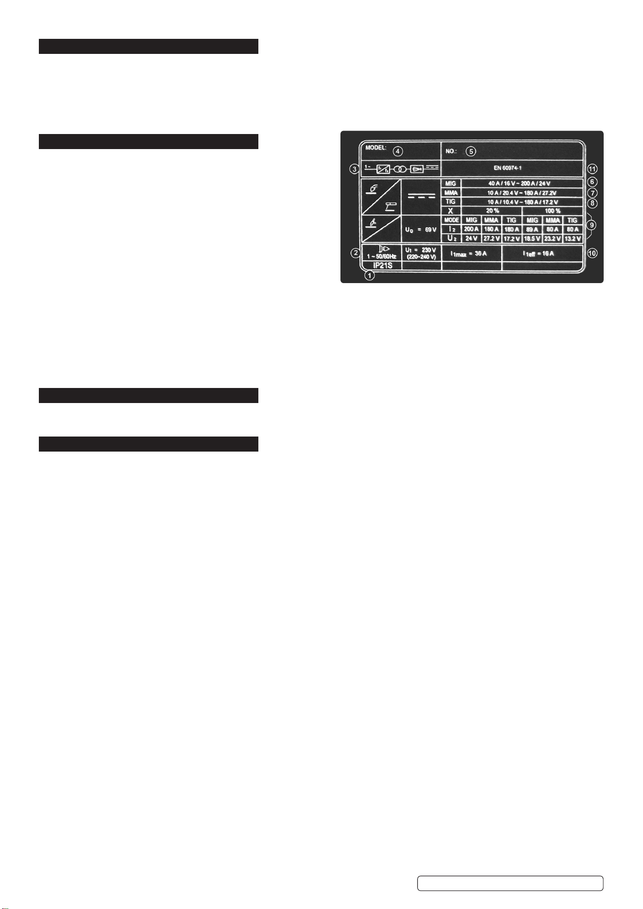
8. RATINGS PLATE
The ratings plate on the inverter gives the following data:
1 Rating of internal protection provided by casing.
2 Symbol for power supply line: 1= Single-phase AC.
3 Symbol for internal structure of the welding machine.
4 Manufacturers Details and Model No.
5 Manufacturers Serial Number for welding machine identification.
6 MIG Output.
7 MMA Output
8 TIG` Output
9 Power Supply
U1: Alternating voltage and power supply frequency of welding
machine. (allowed limit ± 10%)
I1 max: Maximum current absorbed by the line.
I1 eff: Effective current supplied.
10 Duty Cycle
U
º
: Maximum no load voltage.
I
²
, U
²
: Current and corresponding normalised voltage that the welding machine can supply during welding.
X: Welding ratio based on a 10 minute duty cycle. 20% indicates 2 minutes welding and 8 minutes rest, 100% indicates continuous
welding.
11 The EUROPEAN standard relating to the safety and construction of arc welding machines.
9. DUTY CYCLE
When the machine reaches the end of its duty cycle and overheats, the thermostatic switch opens to allow the internal components
to cool. This is denoted by the error page illuminating. Allow the machine to cool and resume use when the error warning clears.
10. MAINTENANCE
WARNING! Remove from mains supply before carrying out any inspection or maintenance.
10.1. WIRE FEED UNIT Check the wire feed unit at regular intervals. The feed roller wire guide plays an important part in obtaining
consistent results. Poor wire feed affects welding. Clean the rollers weekly, especially the feed roller groove, removing all dust
deposits.
10.2. TORCH Protect the torch cable assembly from mechanical wear. Clean the liner from the machine forwards by using compressed
air. If the liner is clogged it must be replaced.
10.3. CHANGING FEED ROLLER (See Section 4.6.)
10.4. CONTACT TIP The contact tip is a consumable item and must be replaced when the hole becomes enlarged or oval. The contact
tip MUST be kept free from spatter to ensure an unimpeded flow of gas. Refer to fig.9 and section 5.4.4 for removal and replacement.
10.5. GAS CUP The gas cup must also be kept clean and free from spatter. Build up of spatter inside the gas cup can cause a short
circuit at the contact tip which will result in either the fuse blowing on the printed circuit card, or expensive machine repairs. To keep
the contact tip free from spatter, we recommend the use of Sealey anti-spatter spray (MIG/722308) available from your
Sealey stockist.
10.6. REPLACING THE LINER Wind the wire back on to the spool and secure it. Unscrew the torch from the machine and undo the brass
nut. The liner should now be visible. Pull it out and replace with a new one.
10.7. Remove the casing periodically and, with a low pressure air flow (max 1bar or 15psi), remove dust from inside the machine.
8 DO NOT direct compressed air onto the electronic circuit boards, these should be cleaned with a very soft brush.
10.8. Ensure that all electrical connections are tight and check the wiring for damage to the insulation.
10.9. Ensure that the casing is correctly replaced and secured before attempting to use the inverter.
10.10. Keep the outside of the machine clean by wiping with a soft, dry cloth.
10.11. For any other service or maintenance, contact your local Sealey service agent.
.
Original Language Version
© Jack Sealey Limited
INVMIG200LCD.V2 Issue:2 (1) 18/01/23

SealeyGroup,KempsonWay,SuffolkBusinessPark,BuryStEdmunds,Suffolk.IP327AR
01284757500 sales@sealey.co.uk www.sealey.co.uk
WEEE REGULATIONS
Dispose of this product at the end of its working life in compliance with the EU Directive on Waste Electrical and Electronic Equipment
(WEEE). When the product is no longer required, it must be disposed of in an environmentally protective way. Contact your local solid
waste authority for recycling information.
Note: It is our policy to continually improve products and as such we reserve the right to alter data, specifications and component parts without prior
notice. Please note that other versions of this product are available. If you require documentation for alternative versions, please email or call
our technical team on technical@sealey.co.uk or 01284 757505.
Important: No Liability is accepted for incorrect use of this product.
Warranty: Guarantee is 12 months from purchase date, proof of which is required for any claim.
ENVIRONMENT PROTECTION
Recycle unwanted materials instead of disposing of them as waste. All tools, accessories and packaging should be sorted,
taken to a recycling centre and disposed of in a manner which is compatible with the environment. When the product
becomes completely unserviceable and requires disposal, drain any fluids (if applicable) into approved containers and
dispose of the product and fluids according to local regulations.
INVMIG200LCD.V2 Issue:2 (1) 18/01/23
Original Language Version
© Jack Sealey Limited
REGISTER YOUR
PURCHASE HERE